EP4292884A1 - Positionierungshilfsvorrichtung und positionierungshilfsverfahren - Google Patents
Positionierungshilfsvorrichtung und positionierungshilfsverfahren Download PDFInfo
- Publication number
- EP4292884A1 EP4292884A1 EP22770298.2A EP22770298A EP4292884A1 EP 4292884 A1 EP4292884 A1 EP 4292884A1 EP 22770298 A EP22770298 A EP 22770298A EP 4292884 A1 EP4292884 A1 EP 4292884A1
- Authority
- EP
- European Patent Office
- Prior art keywords
- connecting rod
- horizontal reference
- rod
- locking
- laser device
- Prior art date
- Legal status (The legal status is an assumption and is not a legal conclusion. Google has not performed a legal analysis and makes no representation as to the accuracy of the status listed.)
- Granted
Links
Images


Classifications
-
- G—PHYSICS
- G01—MEASURING; TESTING
- G01S—RADIO DIRECTION-FINDING; RADIO NAVIGATION; DETERMINING DISTANCE OR VELOCITY BY USE OF RADIO WAVES; LOCATING OR PRESENCE-DETECTING BY USE OF THE REFLECTION OR RERADIATION OF RADIO WAVES; ANALOGOUS ARRANGEMENTS USING OTHER WAVES
- G01S13/00—Systems using the reflection or reradiation of radio waves, e.g. radar systems; Analogous systems using reflection or reradiation of waves whose nature or wavelength is irrelevant or unspecified
- G01S13/88—Radar or analogous systems specially adapted for specific applications
- G01S13/93—Radar or analogous systems specially adapted for specific applications for anti-collision purposes
- G01S13/931—Radar or analogous systems specially adapted for specific applications for anti-collision purposes of land vehicles
-
- B—PERFORMING OPERATIONS; TRANSPORTING
- B60—VEHICLES IN GENERAL
- B60R—VEHICLES, VEHICLE FITTINGS, OR VEHICLE PARTS, NOT OTHERWISE PROVIDED FOR
- B60R11/00—Arrangements for holding or mounting articles, not otherwise provided for
-
- G—PHYSICS
- G01—MEASURING; TESTING
- G01B—MEASURING LENGTH, THICKNESS OR SIMILAR LINEAR DIMENSIONS; MEASURING ANGLES; MEASURING AREAS; MEASURING IRREGULARITIES OF SURFACES OR CONTOURS
- G01B11/00—Measuring arrangements characterised by the use of optical techniques
- G01B11/26—Measuring arrangements characterised by the use of optical techniques for measuring angles or tapers; for testing the alignment of axes
- G01B11/27—Measuring arrangements characterised by the use of optical techniques for measuring angles or tapers; for testing the alignment of axes for testing the alignment of axes
-
- G—PHYSICS
- G01—MEASURING; TESTING
- G01S—RADIO DIRECTION-FINDING; RADIO NAVIGATION; DETERMINING DISTANCE OR VELOCITY BY USE OF RADIO WAVES; LOCATING OR PRESENCE-DETECTING BY USE OF THE REFLECTION OR RERADIATION OF RADIO WAVES; ANALOGOUS ARRANGEMENTS USING OTHER WAVES
- G01S7/00—Details of systems according to groups G01S13/00, G01S15/00, G01S17/00
- G01S7/02—Details of systems according to groups G01S13/00, G01S15/00, G01S17/00 of systems according to group G01S13/00
- G01S7/40—Means for monitoring or calibrating
- G01S7/4052—Means for monitoring or calibrating by simulation of echoes
- G01S7/4082—Means for monitoring or calibrating by simulation of echoes using externally generated reference signals, e.g. via remote reflector or transponder
- G01S7/4086—Means for monitoring or calibrating by simulation of echoes using externally generated reference signals, e.g. via remote reflector or transponder in a calibrating environment, e.g. anechoic chamber
-
- B—PERFORMING OPERATIONS; TRANSPORTING
- B60—VEHICLES IN GENERAL
- B60R—VEHICLES, VEHICLE FITTINGS, OR VEHICLE PARTS, NOT OTHERWISE PROVIDED FOR
- B60R11/00—Arrangements for holding or mounting articles, not otherwise provided for
- B60R2011/0001—Arrangements for holding or mounting articles, not otherwise provided for characterised by position
- B60R2011/004—Arrangements for holding or mounting articles, not otherwise provided for characterised by position outside the vehicle
-
- B—PERFORMING OPERATIONS; TRANSPORTING
- B60—VEHICLES IN GENERAL
- B60R—VEHICLES, VEHICLE FITTINGS, OR VEHICLE PARTS, NOT OTHERWISE PROVIDED FOR
- B60R11/00—Arrangements for holding or mounting articles, not otherwise provided for
- B60R2011/0042—Arrangements for holding or mounting articles, not otherwise provided for characterised by mounting means
- B60R2011/0049—Arrangements for holding or mounting articles, not otherwise provided for characterised by mounting means for non integrated articles
- B60R2011/005—Connection with the vehicle part
- B60R2011/0052—Connection with the vehicle part using screws, bolts, rivets or the like
-
- B—PERFORMING OPERATIONS; TRANSPORTING
- B60—VEHICLES IN GENERAL
- B60R—VEHICLES, VEHICLE FITTINGS, OR VEHICLE PARTS, NOT OTHERWISE PROVIDED FOR
- B60R11/00—Arrangements for holding or mounting articles, not otherwise provided for
- B60R2011/0042—Arrangements for holding or mounting articles, not otherwise provided for characterised by mounting means
- B60R2011/008—Adjustable or movable supports
Definitions
- Typical automobile side components and parts installations have angular requirements. For instance, the installation of a radar assembly in an automobile turn assist system (Turn Assist) requires certain angular requirements based on the automobile side plane.
- Turn Assist automobile turn assist system
- the laser device is horizontally rotatable relative to the horizontal reference rod.
- the laser device may slide along the center line in the lengthwise direction of the horizontal reference rod.
- the positioning assist device further comprises a second locking mechanism for locking the laser device relative to the horizontal reference rod to limit the movement of the laser device relative to the horizontal reference rod.
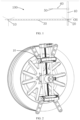
- the first fixator comprises a first installation seat and two first claw assemblies, wherein the two first claw assemblies are clamped on a hub of the front wheel, the first installation seat is located at center positions of the two first claw assemblies, and a first end of the first fixing rod is installed on the first installation seat;
- the second fixator comprises a second installation seat and two second claw assemblies, wherein the second installation seat is located at the center positions of the two second claw assemblies, the two second claw assemblies are clamped to the hub of the rear wheel, and a second end of the first fixing rod is installed on the second installation seat.
- the step of according to the installation direction and the installation angle, adjusting the horizontal reference rod so that an included angle between the horizontal reference rod and the first connecting rod is the same as the installation angle further comprises:
- the first drive module 130 and the second drive module 230 may be a lead screw mechanism, and the first drive module 130 is described herein as an example.
- the embodiment of the present application does not have any limitations as long as the rotation of the driving member 131 can be limited.
- the first installation hole and the second installation hole may both be threaded holes, two ends of the first connecting rod 30 may be respectively provided with threads, and the first connecting rod 30 is fixed between the first installation seat 110 and the second installation seat 120 by the cooperation of the first connecting rod 30 with the first installation hole and the second installation hole.
- the second connecting rod 40 is installed on the second installation seat 120 and perpendicular to the first connecting rod 30. In other embodiments, the second connecting rod 40 may be installed on the ground or other devices as long as it is ensured that the second connecting rod 40 is perpendicular to the first connecting rod 30, without any limitation by this embodiment of the present application.
- the moving part 510 when one end of the moving part 510 is a closed end and the other end is an open end, the moving part 510 is sleeved on the second connecting rod 40 and the closed end of the moving part 510 abuts the top of the second connecting rod 40. At this time, the horizontal reference rod 50 can only rotate around the second connecting rod 40. When two ends of the moving part 510 are open ends, the moving part 510 is sleeved on the second connecting rod 40 and can slide along the second connecting rod 40. At this time, the horizontal reference rod 50 can both rotate around the second connecting rod 40 and slide relative to the second connecting rod 40 along the lengthwise direction of the second connecting rod 40.
- the present application takes the situation that the horizontal reference rod 50 can both rotate around the second connecting rod 40 and slide relative to the second connecting rod 40 along the lengthwise direction of the second connecting rod 40 as an example.
- the first locking mechanism 70 comprises a locking ring, a first locking bolt, and a first locking nut.
- the first locking ring is sleeved on the moving part 510, the two ends of the locking ring are provided with a first via hole and a first through hole through which the first locking bolt passes, and the first locking nut is used for cooperating with the first locking bolt after the first locking bolt passes through the first via hole and the first through hole.
- the first locking mechanism 70 achieves the locking of the horizontal reference rod 50 when the first locking nut is tightened; when the horizontal reference rod 50 needs to rotate or slide relative to the second connecting rod 40, it only requires the first locking bolt to be loosened.
- the first locking ring may be omitted, and the moving part may be provided in an open-loop structure that constitutes the locking ring described above, as shown in Fig. 7 .
- the first locking mechanism 70 can also be other mechanisms, for example, the first locking mechanism comprises two locking nuts, the outer surface of the connecting rod 40 is provided with threads, the two locking nuts are respectively screwed on two ends of the connecting rod, and the moving part is between two nuts.
- the horizontal reference rod 50 can be locked.
- the horizontal reference rod 50 needs to rotate or slide relative to the second connecting rod 40, the two locking nuts are loosened, and at this time, the horizontal reference rod is rotatable about the second connecting rod 40, and the horizontal reference rod is slidable along the second connecting rod 40 between two locking nuts.
- first locking mechanism 70 is not limited to the embodiments of the present invention, and that other means restricting the rotation and sliding of the horizontal reference rod 50 are included in the embodiments of the present application.
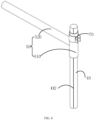
- one of the horizontal reference rod 50 and the second connecting rod is provided with a first arc-shaped scale, and the other is provided with a first reference indication line 02.
- the moving part 510 is provided with the first arc-shaped scale
- the second connecting rod 40 is provided with the first reference indication line O2 (the first reference indication line O2 can be a straight line located on the outer surface of the second connecting rod 40 and extend from the top of the second connecting rod to the bottom of the second connecting rod, as shown in Fig. 6 ) so that when the horizontal reference rod 50 is rotated relative to the second connecting rod 40, the angle at which the horizontal reference rod 50 is rotated can be known according to the first reference indication line O2 and the first arc-shaped scale on the moving part.
- the first reference indication line O2 may also be provided on the moving part.
- the second connecting rod 40 is provided with an arc scale, which extends from the top of the second connecting rod to the bottom of the second connecting rod for easy observation.
- the horizontal angle of the laser device 60 relative to the first connecting rod 30 can be adjusted by the movement of the horizontal reference rod 50 relative to the second connecting rod 40.
- the laser device 60 is movably installed on the horizontal reference rod 50.
- the laser device 60 is movably installed on the horizontal reference rod 50, meaning that the laser device 60 is horizontally rotatable relative to the horizontal reference rod 50.
- the laser device 60 may be rotated horizontally relative to the horizontal reference rod 50, and the positioning assist device further includes a second locking mechanism 80 for locking the laser device 60 relative to the horizontal reference rod 50 to limit the movement (e.g. horizontal rotation) of the laser device 60 relative to the horizontal reference rod 50.
- a second locking mechanism 80 for locking the laser device 60 relative to the horizontal reference rod 50 to limit the movement (e.g. horizontal rotation) of the laser device 60 relative to the horizontal reference rod 50.
- the second locking mechanism 80 comprises a locking plate 81, a second locking bolt 82, and a second locking nut.
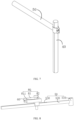
- the locking plate 81 is connected to the laser device 60, the locking plate 81 is perpendicular to the center axis plane of the automobile, the locking plate 81 is provided with an arc-shaped hole 811 for the second locking bolt 82 to pass through, and the horizontal reference rod 50 is provided with a sliding groove 530 for the second locking bolt 82 to pass through; the second locking bolt 82 is slidable along the sliding groove 530 provided along the lengthwise direction of the horizontal reference rod 50, and the second locking nut is used for cooperating with the second locking bolt 82 after the second locking bolt 82 passes through the arc-shaped hole 811 and the sliding groove 530.
- the second locking bolt 82 can slide along the arc direction of the arc-shaped hole 811, and the sum of the radians of the arc-shaped hole 811 is greater than or equal to 180 degrees, so that the horizontal angle of the laser device 60 relative to the horizontal reference rod 50 can be adjusted by the second locking bolt 82 sliding along the arc direction of the arc-shaped hole 811.
- the locking of the laser device 60 relative to the horizontal reference rod 50 can be achieved when the second locking nut is tightened, and the second locking nut is loosened when the laser device 60 needs to be rotated horizontally relative to the horizontal reference rod 50.
- connection of the laser device 60 to the locking plate 81 may be a fixed connection or a movable connection.
- the laser device 60 being fixedly connected to the locking plate 81, or the laser device 60 being movably connected to the locking plate 81, e.g. hinged.
- the laser device is movably connected (e.g. hinged) to the locking plate 81, the laser device can move relative to the locking plate 81 under an external force.
- the laser device 60 can also slide along the lengthwise direction of the horizontal reference rod 50; in order to limit the laser device 60 to slide along other directions, the rotating part 520 of the horizontal reference rod 50 is of a square structure, the locking plate 81 is parallel to the top surface of the rotating part 520, the rotating part 520 is sleeved with a sliding block 90, the sliding block 90 can slide along the lengthwise direction of the horizontal reference rod 50, the sliding block 90 is provided with a second via hole through which the second locking bolt 82 passes, and the second locking bolt passes through the arc-shaped hole, the second via hole, and the sliding groove 530, and then cooperates with the second locking nut.
- the second locking nut is tightened, the locking plate 81 and the sliding block 90 remain relatively fixed, and the sliding block 90 can drive the second locking device 80 and the laser device 60 to slide along the lengthwise direction of the horizontal reference rod 50.
- one of the side of the horizontal reference rod and one side of the sliding block opposite the side of the horizontal reference is provided with a convex rib and the other is provided with a groove for receiving the convex rib.
- the convex rib can slide along the groove.
- the locking plate 81 may be omitted.
- the second locking mechanism 80 comprises a second locking bolt 82 and a second locking nut
- the laser device 60 is installed on the second locking bolt 82
- the second locking bolt passes through the second via hole and the sliding groove 530 and then cooperates with the second locking nut
- the horizontal angle of the laser device 60 relative to the horizontal reference rod 50 can be adjusted by rotating the second locking bolt.
- one of the second locking bolt 82 and the sliding block 90 is provided with a second arc-shaped scale and the other is provided with a second reference indication line.
- the laser device 60 may be movably or fixedly installed on the second locking bolt 82.
- the laser device 60 can slide along the horizontal reference rod 50 in order to enable the laser light emitted by the laser device 60 to form a laser line on the first connecting rod 30, so as to prevent the laser line from being formed on the first connecting rod 30 due to the shielding of the horizontal reference rod 50 when the laser device 60 emits laser light downward.
- the length of the first connecting rod is longer than the length of the rotating part 520 of the horizontal reference rod 50.
- the mechanism by which the laser device 60 moves and locks relative to the horizontal reference rod 50 is not limited to the embodiments of the present application, and that other mechanisms that enable the laser device to move and lock relative to the horizontal reference rod are included in the embodiments of the present application.
- the side position of the radar assembly to be installed on one side of the automobile can be determined, namely, the angle of the energy receiving and transmitting surface of the radar assembly relative to one side of the automobile is determined.
- the sliding block 90 can be slid according to the requirements.
- embodiments of the present application provide a positioning assist method including the above-described positioning assist device for assisting in the installation of the above-described radar assembly to be installed.
- Step S10 adjust the first fixator 10 and the second fixator 20 to ensure that a vertical plane, where a center line in a lengthwise direction of the first connecting rod 30 is located, is parallel to the center axis plane of the automobile.
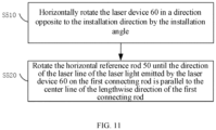
- Step S20 rotate the laser device 60 until the direction of the laser line of the laser light emitted by the laser device on the horizontal reference rod 50 is parallel to the center line of the lengthwise direction of the horizontal reference rod.
- Step S50 according to the installation direction and the installation angle, adjust the horizontal reference rod 50 so that the included angle between the horizontal reference rod 50 and the first connecting rod 30 is the same as the installation angle, and the deflection direction of the horizontal reference rod 50 relative to the first connecting rod 30 is the same as the installation direction.
- the step of according to the installation direction and the installation angle, adjusting the horizontal reference rod 50 so that the included angle between the horizontal reference rod 50 and the first connecting rod is the same as the installation angle further includes:
- Embodiments of the present invention provide a positioning assist device and method for determining the installation position of a radar assembly to be installed on a side surface of one side of an automobile by adjusting the laser device and the horizontal reference rod.
- the operation is simple, convenient, and fast, and the installation precision is high.
Landscapes
- Engineering & Computer Science (AREA)
- Physics & Mathematics (AREA)
- Radar, Positioning & Navigation (AREA)
- Remote Sensing (AREA)
- General Physics & Mathematics (AREA)
- Mechanical Engineering (AREA)
- Computer Networks & Wireless Communication (AREA)
- Electromagnetism (AREA)
- Optical Radar Systems And Details Thereof (AREA)
Applications Claiming Priority (2)
| Application Number | Priority Date | Filing Date | Title |
|---|---|---|---|
| CN202110296223.7A CN112937458B (zh) | 2021-03-19 | 2021-03-19 | 一种辅助定位装置及定位方法 |
| PCT/CN2022/078626 WO2022193943A1 (zh) | 2021-03-19 | 2022-03-01 | 一种辅助定位装置及定位方法 |
Publications (3)
| Publication Number | Publication Date |
|---|---|
| EP4292884A1 true EP4292884A1 (de) | 2023-12-20 |
| EP4292884A4 EP4292884A4 (de) | 2024-03-20 |
| EP4292884B1 EP4292884B1 (de) | 2024-11-20 |
Family
ID=76227208
Family Applications (1)
| Application Number | Title | Priority Date | Filing Date |
|---|---|---|---|
| EP22770298.2A Active EP4292884B1 (de) | 2021-03-19 | 2022-03-01 | Positionierungshilfsvorrichtung und positionierungshilfsverfahren |
Country Status (4)
| Country | Link |
|---|---|
| US (1) | US12583398B2 (de) |
| EP (1) | EP4292884B1 (de) |
| CN (1) | CN112937458B (de) |
| WO (1) | WO2022193943A1 (de) |
Families Citing this family (5)
| Publication number | Priority date | Publication date | Assignee | Title |
|---|---|---|---|---|
| USD1072146S1 (en) * | 2020-10-28 | 2025-04-22 | S&P Collective, LLC | Target apparatus for firearms and archery |
| CN112937458B (zh) * | 2021-03-19 | 2025-04-04 | 深圳市道通科技股份有限公司 | 一种辅助定位装置及定位方法 |
| CN114114219B (zh) * | 2021-11-30 | 2025-11-25 | 深圳市道通科技股份有限公司 | 车载雷达标定设备及方法 |
| CN120651149B (zh) * | 2025-07-15 | 2025-12-02 | 中交路桥华南工程有限公司 | 一种小箱梁安装轴线偏差实时监测仪 |
| CN121252695A (zh) * | 2025-10-30 | 2026-01-02 | 太仓戴尔塔精密科技有限公司 | 一种带手柄的穿刺针轴线准直偏心度测量设备 |
Family Cites Families (12)
| Publication number | Priority date | Publication date | Assignee | Title |
|---|---|---|---|---|
| US4330945A (en) * | 1980-03-31 | 1982-05-25 | Kansas Jack, Inc. | Vehicle frame and body alignment apparatus |
| SE459615B (sv) | 1986-10-01 | 1989-07-17 | Torgny Hoervallius | Saett och anordning foer uppmaetning av hjulvinklar i ett motorfordons framvagn |
| FR2825157B1 (fr) | 2001-05-23 | 2006-02-17 | Renault | Dispositif de verification de l'alignement d'un radar de vehicule automobile |
| US6809806B1 (en) | 2003-05-27 | 2004-10-26 | International Truck Intellectual Property Company, Llc | Apparatus and method for verifying the beam axis of front-looking land vehicle transceiver antenna |
| CN106772320B (zh) * | 2017-03-10 | 2023-06-16 | 中国科学技术大学 | 一种激光雷达的发射光束方向初步调整垂直装置 |
| CN108051815B (zh) * | 2017-12-07 | 2023-11-07 | 上海为彪汽配制造有限公司 | 一种装设毫米波雷达的汽车和安装该毫米波雷达的方法、组件 |
| CN210139827U (zh) | 2019-04-30 | 2020-03-13 | 深圳森云智能科技有限公司 | 一种变道辅助系统安装装置 |
| US12158358B2 (en) * | 2019-09-23 | 2024-12-03 | Christopher Dennis Gilliand | Vehicle leveling device and method |
| CN111830474B (zh) * | 2020-07-23 | 2023-04-21 | 烟台开发区海德科技有限公司 | 汽车后雷达标定装置的定位装置及方法 |
| CN112045602B (zh) * | 2020-09-21 | 2024-12-06 | 深圳市道通科技股份有限公司 | 一种轮毂夹持装置 |
| CN112937458B (zh) | 2021-03-19 | 2025-04-04 | 深圳市道通科技股份有限公司 | 一种辅助定位装置及定位方法 |
| CN215552899U (zh) * | 2021-03-19 | 2022-01-18 | 深圳市道通科技股份有限公司 | 一种辅助定位装置 |
-
2021
- 2021-03-19 CN CN202110296223.7A patent/CN112937458B/zh active Active
-
2022
- 2022-03-01 WO PCT/CN2022/078626 patent/WO2022193943A1/zh not_active Ceased
- 2022-03-01 US US18/282,546 patent/US12583398B2/en active Active
- 2022-03-01 EP EP22770298.2A patent/EP4292884B1/de active Active
Also Published As
| Publication number | Publication date |
|---|---|
| US12583398B2 (en) | 2026-03-24 |
| US20240157888A1 (en) | 2024-05-16 |
| CN112937458A (zh) | 2021-06-11 |
| CN112937458B (zh) | 2025-04-04 |
| EP4292884B1 (de) | 2024-11-20 |
| WO2022193943A1 (zh) | 2022-09-22 |
| EP4292884A4 (de) | 2024-03-20 |
Similar Documents
| Publication | Publication Date | Title |
|---|---|---|
| EP4292884A1 (de) | Positionierungshilfsvorrichtung und positionierungshilfsverfahren | |
| US20120211624A1 (en) | Adjusting mechanism for adjusting rotary angle and antenna system therewith | |
| EP3177114A1 (de) | Verfahren zur justage der primärseite eines röntgendiffraktometers | |
| CN111442745A (zh) | 一种摆正校准设备的装置及方法 | |
| US20090113732A1 (en) | Apparatus and Method for Theodolite Support | |
| CN112161589B (zh) | 车辆标定设备 | |
| CN1060864C (zh) | 多维可调工作平台 | |
| CN113534081B (zh) | 一种形变监测雷达精度的检测方法及装置 | |
| EP4075124A1 (de) | Einstell- und positionierungsvorrichtung und -verfahren für eine strahlenquellenanordnung und strahlungsabtastbildgebungsvorrichtung | |
| CN110376700B (zh) | 一种基于数字微镜单元的光路调整机构及其调整方法 | |
| CN106764293A (zh) | 安全光幕的上梁安装支架以及角度调节座 | |
| CN215552899U (zh) | 一种辅助定位装置 | |
| CN115016089B (zh) | 一种用于分体积木反射式风洞纹影仪的光路快速找准方法 | |
| CN105807390B (zh) | 一种用于校对大间距镜筒光轴的辅助装置 | |
| CN111601642B (zh) | 一种调节机构、光距尺系统和医疗设备 | |
| CN114079711B (zh) | 线阵相机激光补光共线调整装置和调整方法 | |
| CN208827989U (zh) | 一种前桥总成装配转向角检测调整夹具 | |
| US4226392A (en) | Three dimensional fine focus detector mount | |
| CN119620213A (zh) | 射线检查系统 | |
| CN115561871B (zh) | 一种光学镜片装调装置及其调整方法 | |
| CN117907347A (zh) | 用于弓形法反射率测试系统的天线指向校准装置及方法 | |
| CN216013641U (zh) | 一种标定车载雷达与摄像头的装置 | |
| CN112405388B (zh) | 雷达天线测试装置 | |
| CN207742097U (zh) | 一种逆反射标志测量仪的入射角度调节装置 | |
| CN220749664U (zh) | 一种双激光器调节安装座 |
Legal Events
| Date | Code | Title | Description |
|---|---|---|---|
| STAA | Information on the status of an ep patent application or granted ep patent |
Free format text: STATUS: THE INTERNATIONAL PUBLICATION HAS BEEN MADE |
|
| PUAI | Public reference made under article 153(3) epc to a published international application that has entered the european phase |
Free format text: ORIGINAL CODE: 0009012 |
|
| STAA | Information on the status of an ep patent application or granted ep patent |
Free format text: STATUS: REQUEST FOR EXAMINATION WAS MADE |
|
| 17P | Request for examination filed |
Effective date: 20230913 |
|
| AK | Designated contracting states |
Kind code of ref document: A1 Designated state(s): AL AT BE BG CH CY CZ DE DK EE ES FI FR GB GR HR HU IE IS IT LI LT LU LV MC MK MT NL NO PL PT RO RS SE SI SK SM TR |
|
| REG | Reference to a national code |
Ref country code: DE Ref legal event code: R079 Free format text: PREVIOUS MAIN CLASS: B60R0011000000 Ipc: G01B0011270000 Ref document number: 602022007999 Country of ref document: DE |
|
| A4 | Supplementary search report drawn up and despatched |
Effective date: 20240219 |
|
| RIC1 | Information provided on ipc code assigned before grant |
Ipc: G01S 7/40 20060101ALI20240213BHEP Ipc: G01S 13/931 20200101ALI20240213BHEP Ipc: G01B 11/27 20060101AFI20240213BHEP |
|
| RAP3 | Party data changed (applicant data changed or rights of an application transferred) |
Owner name: AUTEL INTELLIGENT TECHNOLOGY CORP. LTD. |
|
| DAV | Request for validation of the european patent (deleted) | ||
| DAX | Request for extension of the european patent (deleted) | ||
| GRAP | Despatch of communication of intention to grant a patent |
Free format text: ORIGINAL CODE: EPIDOSNIGR1 |
|
| STAA | Information on the status of an ep patent application or granted ep patent |
Free format text: STATUS: GRANT OF PATENT IS INTENDED |
|
| INTG | Intention to grant announced |
Effective date: 20240719 |
|
| GRAS | Grant fee paid |
Free format text: ORIGINAL CODE: EPIDOSNIGR3 |
|
| GRAA | (expected) grant |
Free format text: ORIGINAL CODE: 0009210 |
|
| STAA | Information on the status of an ep patent application or granted ep patent |
Free format text: STATUS: THE PATENT HAS BEEN GRANTED |
|
| AK | Designated contracting states |
Kind code of ref document: B1 Designated state(s): AL AT BE BG CH CY CZ DE DK EE ES FI FR GB GR HR HU IE IS IT LI LT LU LV MC MK MT NL NO PL PT RO RS SE SI SK SM TR |
|
| REG | Reference to a national code |
Ref country code: GB Ref legal event code: FG4D |
|
| REG | Reference to a national code |
Ref country code: CH Ref legal event code: EP |
|
| REG | Reference to a national code |
Ref country code: DE Ref legal event code: R096 Ref document number: 602022007999 Country of ref document: DE |
|
| REG | Reference to a national code |
Ref country code: IE Ref legal event code: FG4D |
|
| REG | Reference to a national code |
Ref country code: LT Ref legal event code: MG9D |
|
| REG | Reference to a national code |
Ref country code: NL Ref legal event code: MP Effective date: 20241120 |
|
| PG25 | Lapsed in a contracting state [announced via postgrant information from national office to epo] |
Ref country code: IS Free format text: LAPSE BECAUSE OF FAILURE TO SUBMIT A TRANSLATION OF THE DESCRIPTION OR TO PAY THE FEE WITHIN THE PRESCRIBED TIME-LIMIT Effective date: 20250320 Ref country code: PT Free format text: LAPSE BECAUSE OF FAILURE TO SUBMIT A TRANSLATION OF THE DESCRIPTION OR TO PAY THE FEE WITHIN THE PRESCRIBED TIME-LIMIT Effective date: 20250320 Ref country code: HR Free format text: LAPSE BECAUSE OF FAILURE TO SUBMIT A TRANSLATION OF THE DESCRIPTION OR TO PAY THE FEE WITHIN THE PRESCRIBED TIME-LIMIT Effective date: 20241120 |
|
| PGFP | Annual fee paid to national office [announced via postgrant information from national office to epo] |
Ref country code: DE Payment date: 20250319 Year of fee payment: 4 |
|
| PG25 | Lapsed in a contracting state [announced via postgrant information from national office to epo] |
Ref country code: FI Free format text: LAPSE BECAUSE OF FAILURE TO SUBMIT A TRANSLATION OF THE DESCRIPTION OR TO PAY THE FEE WITHIN THE PRESCRIBED TIME-LIMIT Effective date: 20241120 Ref country code: NL Free format text: LAPSE BECAUSE OF FAILURE TO SUBMIT A TRANSLATION OF THE DESCRIPTION OR TO PAY THE FEE WITHIN THE PRESCRIBED TIME-LIMIT Effective date: 20241120 |
|
| REG | Reference to a national code |
Ref country code: AT Ref legal event code: MK05 Ref document number: 1743918 Country of ref document: AT Kind code of ref document: T Effective date: 20241120 |
|
| PG25 | Lapsed in a contracting state [announced via postgrant information from national office to epo] |
Ref country code: BG Free format text: LAPSE BECAUSE OF FAILURE TO SUBMIT A TRANSLATION OF THE DESCRIPTION OR TO PAY THE FEE WITHIN THE PRESCRIBED TIME-LIMIT Effective date: 20241120 |
|
| PG25 | Lapsed in a contracting state [announced via postgrant information from national office to epo] |
Ref country code: ES Free format text: LAPSE BECAUSE OF FAILURE TO SUBMIT A TRANSLATION OF THE DESCRIPTION OR TO PAY THE FEE WITHIN THE PRESCRIBED TIME-LIMIT Effective date: 20241120 |
|
| PG25 | Lapsed in a contracting state [announced via postgrant information from national office to epo] |
Ref country code: NO Free format text: LAPSE BECAUSE OF FAILURE TO SUBMIT A TRANSLATION OF THE DESCRIPTION OR TO PAY THE FEE WITHIN THE PRESCRIBED TIME-LIMIT Effective date: 20250220 |
|
| PG25 | Lapsed in a contracting state [announced via postgrant information from national office to epo] |
Ref country code: GR Free format text: LAPSE BECAUSE OF FAILURE TO SUBMIT A TRANSLATION OF THE DESCRIPTION OR TO PAY THE FEE WITHIN THE PRESCRIBED TIME-LIMIT Effective date: 20250221 Ref country code: AT Free format text: LAPSE BECAUSE OF FAILURE TO SUBMIT A TRANSLATION OF THE DESCRIPTION OR TO PAY THE FEE WITHIN THE PRESCRIBED TIME-LIMIT Effective date: 20241120 Ref country code: LV Free format text: LAPSE BECAUSE OF FAILURE TO SUBMIT A TRANSLATION OF THE DESCRIPTION OR TO PAY THE FEE WITHIN THE PRESCRIBED TIME-LIMIT Effective date: 20241120 |
|
| PG25 | Lapsed in a contracting state [announced via postgrant information from national office to epo] |
Ref country code: PL Free format text: LAPSE BECAUSE OF FAILURE TO SUBMIT A TRANSLATION OF THE DESCRIPTION OR TO PAY THE FEE WITHIN THE PRESCRIBED TIME-LIMIT Effective date: 20241120 |
|
| PGFP | Annual fee paid to national office [announced via postgrant information from national office to epo] |
Ref country code: FR Payment date: 20250324 Year of fee payment: 4 |
|
| PG25 | Lapsed in a contracting state [announced via postgrant information from national office to epo] |
Ref country code: RS Free format text: LAPSE BECAUSE OF FAILURE TO SUBMIT A TRANSLATION OF THE DESCRIPTION OR TO PAY THE FEE WITHIN THE PRESCRIBED TIME-LIMIT Effective date: 20250220 |
|
| PG25 | Lapsed in a contracting state [announced via postgrant information from national office to epo] |
Ref country code: SM Free format text: LAPSE BECAUSE OF FAILURE TO SUBMIT A TRANSLATION OF THE DESCRIPTION OR TO PAY THE FEE WITHIN THE PRESCRIBED TIME-LIMIT Effective date: 20241120 |
|
| PG25 | Lapsed in a contracting state [announced via postgrant information from national office to epo] |
Ref country code: DK Free format text: LAPSE BECAUSE OF FAILURE TO SUBMIT A TRANSLATION OF THE DESCRIPTION OR TO PAY THE FEE WITHIN THE PRESCRIBED TIME-LIMIT Effective date: 20241120 |
|
| PG25 | Lapsed in a contracting state [announced via postgrant information from national office to epo] |
Ref country code: EE Free format text: LAPSE BECAUSE OF FAILURE TO SUBMIT A TRANSLATION OF THE DESCRIPTION OR TO PAY THE FEE WITHIN THE PRESCRIBED TIME-LIMIT Effective date: 20241120 |
|
| PG25 | Lapsed in a contracting state [announced via postgrant information from national office to epo] |
Ref country code: RO Free format text: LAPSE BECAUSE OF FAILURE TO SUBMIT A TRANSLATION OF THE DESCRIPTION OR TO PAY THE FEE WITHIN THE PRESCRIBED TIME-LIMIT Effective date: 20241120 |
|
| PG25 | Lapsed in a contracting state [announced via postgrant information from national office to epo] |
Ref country code: SK Free format text: LAPSE BECAUSE OF FAILURE TO SUBMIT A TRANSLATION OF THE DESCRIPTION OR TO PAY THE FEE WITHIN THE PRESCRIBED TIME-LIMIT Effective date: 20241120 |
|
| PG25 | Lapsed in a contracting state [announced via postgrant information from national office to epo] |
Ref country code: CZ Free format text: LAPSE BECAUSE OF FAILURE TO SUBMIT A TRANSLATION OF THE DESCRIPTION OR TO PAY THE FEE WITHIN THE PRESCRIBED TIME-LIMIT Effective date: 20241120 |
|
| PG25 | Lapsed in a contracting state [announced via postgrant information from national office to epo] |
Ref country code: IT Free format text: LAPSE BECAUSE OF FAILURE TO SUBMIT A TRANSLATION OF THE DESCRIPTION OR TO PAY THE FEE WITHIN THE PRESCRIBED TIME-LIMIT Effective date: 20241120 |
|
| REG | Reference to a national code |
Ref country code: DE Ref legal event code: R097 Ref document number: 602022007999 Country of ref document: DE |
|
| PG25 | Lapsed in a contracting state [announced via postgrant information from national office to epo] |
Ref country code: SE Free format text: LAPSE BECAUSE OF FAILURE TO SUBMIT A TRANSLATION OF THE DESCRIPTION OR TO PAY THE FEE WITHIN THE PRESCRIBED TIME-LIMIT Effective date: 20241120 |
|
| PLBE | No opposition filed within time limit |
Free format text: ORIGINAL CODE: 0009261 |
|
| STAA | Information on the status of an ep patent application or granted ep patent |
Free format text: STATUS: NO OPPOSITION FILED WITHIN TIME LIMIT |
|
| PG25 | Lapsed in a contracting state [announced via postgrant information from national office to epo] |
Ref country code: MC Free format text: LAPSE BECAUSE OF FAILURE TO SUBMIT A TRANSLATION OF THE DESCRIPTION OR TO PAY THE FEE WITHIN THE PRESCRIBED TIME-LIMIT Effective date: 20241120 |
|
| 26N | No opposition filed |
Effective date: 20250821 |
|
| REG | Reference to a national code |
Ref country code: CH Ref legal event code: H13 Free format text: ST27 STATUS EVENT CODE: U-0-0-H10-H13 (AS PROVIDED BY THE NATIONAL OFFICE) Effective date: 20251023 |
|
| PG25 | Lapsed in a contracting state [announced via postgrant information from national office to epo] |
Ref country code: LU Free format text: LAPSE BECAUSE OF NON-PAYMENT OF DUE FEES Effective date: 20250301 |
|
| REG | Reference to a national code |
Ref country code: BE Ref legal event code: MM Effective date: 20250331 |
|
| PG25 | Lapsed in a contracting state [announced via postgrant information from national office to epo] |
Ref country code: BE Free format text: LAPSE BECAUSE OF NON-PAYMENT OF DUE FEES Effective date: 20250331 |
|
| PG25 | Lapsed in a contracting state [announced via postgrant information from national office to epo] |
Ref country code: CH Free format text: LAPSE BECAUSE OF NON-PAYMENT OF DUE FEES Effective date: 20250331 |
|
| PG25 | Lapsed in a contracting state [announced via postgrant information from national office to epo] |
Ref country code: IE Free format text: LAPSE BECAUSE OF NON-PAYMENT OF DUE FEES Effective date: 20250301 |