EP4292884B1 - Positionierungshilfsvorrichtung und positionierungshilfsverfahren - Google Patents
Positionierungshilfsvorrichtung und positionierungshilfsverfahren Download PDFInfo
- Publication number
- EP4292884B1 EP4292884B1 EP22770298.2A EP22770298A EP4292884B1 EP 4292884 B1 EP4292884 B1 EP 4292884B1 EP 22770298 A EP22770298 A EP 22770298A EP 4292884 B1 EP4292884 B1 EP 4292884B1
- Authority
- EP
- European Patent Office
- Prior art keywords
- connecting rod
- horizontal reference
- rod
- locking
- laser device
- Prior art date
- Legal status (The legal status is an assumption and is not a legal conclusion. Google has not performed a legal analysis and makes no representation as to the accuracy of the status listed.)
- Active
Links
Images


Classifications
-
- G—PHYSICS
- G01—MEASURING; TESTING
- G01S—RADIO DIRECTION-FINDING; RADIO NAVIGATION; DETERMINING DISTANCE OR VELOCITY BY USE OF RADIO WAVES; LOCATING OR PRESENCE-DETECTING BY USE OF THE REFLECTION OR RERADIATION OF RADIO WAVES; ANALOGOUS ARRANGEMENTS USING OTHER WAVES
- G01S13/00—Systems using the reflection or reradiation of radio waves, e.g. radar systems; Analogous systems using reflection or reradiation of waves whose nature or wavelength is irrelevant or unspecified
- G01S13/88—Radar or analogous systems specially adapted for specific applications
- G01S13/93—Radar or analogous systems specially adapted for specific applications for anti-collision purposes
- G01S13/931—Radar or analogous systems specially adapted for specific applications for anti-collision purposes of land vehicles
-
- B—PERFORMING OPERATIONS; TRANSPORTING
- B60—VEHICLES IN GENERAL
- B60R—VEHICLES, VEHICLE FITTINGS, OR VEHICLE PARTS, NOT OTHERWISE PROVIDED FOR
- B60R11/00—Arrangements for holding or mounting articles, not otherwise provided for
-
- G—PHYSICS
- G01—MEASURING; TESTING
- G01B—MEASURING LENGTH, THICKNESS OR SIMILAR LINEAR DIMENSIONS; MEASURING ANGLES; MEASURING AREAS; MEASURING IRREGULARITIES OF SURFACES OR CONTOURS
- G01B11/00—Measuring arrangements characterised by the use of optical techniques
- G01B11/26—Measuring arrangements characterised by the use of optical techniques for measuring angles or tapers; for testing the alignment of axes
- G01B11/27—Measuring arrangements characterised by the use of optical techniques for measuring angles or tapers; for testing the alignment of axes for testing the alignment of axes
-
- G—PHYSICS
- G01—MEASURING; TESTING
- G01S—RADIO DIRECTION-FINDING; RADIO NAVIGATION; DETERMINING DISTANCE OR VELOCITY BY USE OF RADIO WAVES; LOCATING OR PRESENCE-DETECTING BY USE OF THE REFLECTION OR RERADIATION OF RADIO WAVES; ANALOGOUS ARRANGEMENTS USING OTHER WAVES
- G01S7/00—Details of systems according to groups G01S13/00, G01S15/00, G01S17/00
- G01S7/02—Details of systems according to groups G01S13/00, G01S15/00, G01S17/00 of systems according to group G01S13/00
- G01S7/40—Means for monitoring or calibrating
- G01S7/4052—Means for monitoring or calibrating by simulation of echoes
- G01S7/4082—Means for monitoring or calibrating by simulation of echoes using externally generated reference signals, e.g. via remote reflector or transponder
- G01S7/4086—Means for monitoring or calibrating by simulation of echoes using externally generated reference signals, e.g. via remote reflector or transponder in a calibrating environment, e.g. anechoic chamber
-
- B—PERFORMING OPERATIONS; TRANSPORTING
- B60—VEHICLES IN GENERAL
- B60R—VEHICLES, VEHICLE FITTINGS, OR VEHICLE PARTS, NOT OTHERWISE PROVIDED FOR
- B60R11/00—Arrangements for holding or mounting articles, not otherwise provided for
- B60R2011/0001—Arrangements for holding or mounting articles, not otherwise provided for characterised by position
- B60R2011/004—Arrangements for holding or mounting articles, not otherwise provided for characterised by position outside the vehicle
-
- B—PERFORMING OPERATIONS; TRANSPORTING
- B60—VEHICLES IN GENERAL
- B60R—VEHICLES, VEHICLE FITTINGS, OR VEHICLE PARTS, NOT OTHERWISE PROVIDED FOR
- B60R11/00—Arrangements for holding or mounting articles, not otherwise provided for
- B60R2011/0042—Arrangements for holding or mounting articles, not otherwise provided for characterised by mounting means
- B60R2011/0049—Arrangements for holding or mounting articles, not otherwise provided for characterised by mounting means for non integrated articles
- B60R2011/005—Connection with the vehicle part
- B60R2011/0052—Connection with the vehicle part using screws, bolts, rivets or the like
-
- B—PERFORMING OPERATIONS; TRANSPORTING
- B60—VEHICLES IN GENERAL
- B60R—VEHICLES, VEHICLE FITTINGS, OR VEHICLE PARTS, NOT OTHERWISE PROVIDED FOR
- B60R11/00—Arrangements for holding or mounting articles, not otherwise provided for
- B60R2011/0042—Arrangements for holding or mounting articles, not otherwise provided for characterised by mounting means
- B60R2011/008—Adjustable or movable supports
Definitions
- the embodiments of the present application relate to the technical field of automobiles, in particular to a positioning assist device and a positioning assist method.
- Typical automobile side components and parts installations have angular requirements. For instance, the installation of a radar assembly in an automobile turn assist system (Turn Assist) requires certain angular requirements based on the automobile side plane.
- CN108051815A discloses a car equipped with millimeter wave radar, and a method and assembly of mounting a millimeter wave radar.
- the inventors have found that in the prior art the angle and direction of the installation position are simply measured and fixed by manual use of an angle ruler and like measuring instruments, and these methods are inefficient and offer poor angle precision in practice, so that the installation angle cannot be guaranteed to be within the error range required by the angle of a component and a part (radar assembly). Therefore, the safety performance of an automobile cannot be guaranteed.
- Embodiments of the present invention are intended to provide a positioning assist device and a positioning assist method for improving the precision of the installation angle of a radar assembly to be installed, thereby improving the safety performance of an automobile.
- a positioning assist device including:
- the laser device is horizontally rotatable relative to the horizontal reference rod.
- the laser device may slide along the center line in the lengthwise direction of the horizontal reference rod.
- the horizontal reference rod is slidable relative to the second connecting rod along the lengthwise direction of the second connecting rod.
- the horizontal reference rod comprises a moving part and a rotating part extending vertically from the moving part
- the moving part is sleeved on the second connecting rod
- the moving part can slide relative to the second connecting rod along the lengthwise direction of the second connecting rod
- the rotating part can rotate relative to the second connecting rod
- the laser device is movably installed on the rotating part.
- the positioning assist device comprises a first locking mechanism, wherein the first locking mechanism can lock the horizontal reference rod relative to the second connecting rod to limit the movement of the horizontal reference rod relative to the second connecting rod.
- the first locking mechanism comprises a locking ring, a first locking bolt, and a first locking nut; two ends of the locking ring are provided with a first via hole and a first through hole through which the first locking bolt passes, the first locking ring is sleeved on the moving part, and the first locking nut is used for cooperating with the first locking bolt after the first locking bolt passes through the first via hole and the first through hole.
- one of the horizontal reference rod and the second connecting rod is provided with a first arc-shaped scale, and the other is provided with a first reference indication line.
- the positioning assist device further comprises a second locking mechanism for locking the laser device relative to the horizontal reference rod to limit the movement of the laser device relative to the horizontal reference rod.
- the second locking mechanism comprises a locking plate, a second locking bolt, and a second locking nut, wherein the locking plate is fixed to the laser device, the locking plate is provided with an arc-shaped hole for the second locking bolt to pass through, the horizontal reference rod is provided with a sliding groove for the second locking bolt to pass through, and the second locking nut is used for cooperating with the second locking bolt after the second locking bolt passes through the arc-shaped hole and the sliding groove; wherein the second bolt can slide in an arc direction of the arc-shaped hole, and the sum of radians of the arc-shaped holes is greater than or equal to 180 degrees.
- a sliding block is sleeved on the horizontal reference rod, the sliding block can slide along the lengthwise direction of the horizontal reference rod, a second via hole through which the second locking bolt passes is provided on the sliding block, and the second locking bolt cooperates with the second locking nut after passing through the arc-shaped hole, the second via hole, and the sliding groove; wherein when the second locking nut is tightened, the second locking nut abuts against the sliding block.
- a second arc-shaped scale is provided on the arc-shaped hole, and a second reference indication line is provided on the second locking bolt.
- the first fixator comprises a first installation seat and two first claw assemblies, wherein the two first claw assemblies are clamped on a hub of the front wheel, the first installation seat is located at center positions of the two first claw assemblies, and a first end of the first fixing rod is installed on the first installation seat;
- the second fixator comprises a second installation seat and two second claw assemblies, wherein the second installation seat is located at the center positions of the two second claw assemblies, the two second claw assemblies are clamped to the hub of the rear wheel, and a second end of the first fixing rod is installed on the second installation seat.
- Embodiments of the present invention further provide a positioning assist method including the above-described positioning assist device, the method comprising:
- the step of according to the installation direction and the installation angle, adjusting the horizontal reference rod so that an included angle between the horizontal reference rod and the first connecting rod is the same as the installation angle further comprises:
- Embodiments of the present invention provide a positioning assist device and a positioning assist method for determining the installation position of a radar assembly to be installed on a side surface of one side of an automobile by adjusting the laser device and the horizontal reference rod.
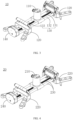
- a positioning assist device comprising a first fixator 10, a second fixator 20, a first connecting rod 30, a second connecting rod 40, a horizontal reference rod 50, and a laser device 60.
- the first fixator 10 is installed on a front wheel on one side of an automobile (as shown in Fig. 2 )
- the second fixator 20 is installed on a rear wheel on one side of the automobile, and the first fixator 10 and the second fixator 20 are located on the same side of the automobile.
- the first connecting rod 30 is connected between the first fixator 10 and the second fixator 20.
- a vertical plane where a center line O1 along the lengthwise direction of the first connecting rod 30 is located is parallel to a center axis plane of the automobile.
- the second connecting rod 40 is disposed perpendicular to the first connecting rod 30.
- the horizontal reference rod 50 is installed on the second connecting rod 40 and is rotatable around the second connecting rod 40, and a horizontal plane where the center line along the lengthwise direction of the horizontal reference rod 50 is located is perpendicular to the center axis plane of the automobile.
- the laser device 60 is movably installed on the horizontal reference rod 50, the laser device 60 is used for emitting laser light downward to form a laser line on an object located under the laser device 60, and the horizontal angle of the laser device 60 relative to the horizontal reference rod 50 can be adjusted to be the angle, relative to the center axis plane of the automobile, of the energy receiving and transmitting surface of a radar assembly to be installed when the radar assembly to be installed is installed on one side of the automobile.
- the horizontal angle of the laser device 60 relative to the first connecting rod 30 is the angle between the direction of the laser line emitted by the laser device 60 and the center line along the lengthwise direction of the first connecting rod 30 in the horizontal plane where the center line along the lengthwise direction of the first connecting rod 30 is located.
- the central axial plane of the automobile means a plane perpendicular to the ground and passing through the middle points of the two front wheels and the middle points of the two rear wheels of the automobile.
- the energy receiving and transmitting surface of the radar assembly to be installed means the antenna plane of the radar or a plane parallel to the antenna plane of the radar.
- one side of the automobile includes places under a rear view mirror of the automobile, or at a side guard rail of the automobile.
- the first fixator 10 and the second holder 20 may have the same structure, and both may be a hub clamping device.
- the first fixator 10 comprises a first installation seat 110, two first claw assemblies 120, a first drive module 130, and a first locking module 140.
- the first installation seat 110 is located at the central positions of the two first claw assemblies 120, and a first end of the first connecting rod 30 is installed on the first installation seat 110.
- the two first claw assemblies 120 are clamped to the hub of the front wheel; the two first claw assemblies 120 are installed on the first drive module 130; the first drive module 130 is used for synchronously driving the two first claw assemblies 120 to move, so that the two first claw assemblies 120 can move towards or away from each other synchronously relative to the first installation seat 110, so as to adapt to hubs of different sizes; the first locking module 140 is used for locking the first drive module 130, so as to ensure that the two first claw assemblies 120 are fixed.
- the first drive module 130 and the second drive module 230 may be a lead screw mechanism, and the first drive module 130 is described herein as an example.
- the first drive module 130 includes a guide assembly for guiding the movement of the two first claw assemblies 120, and a driving member 131 for synchronously driving the two first claw assemblies 120 toward or away from each other.
- the two first claw assemblies 120 move synchronously by the same distance, so as to ensure that the first installation seat 110 is always in the middle of the two first claw assemblies 120, and ensure that the central axis of the first installation seat 110 coincides with the central axis of its the installation hub.
- the guide assembly comprises a first guide post 132, a second guide post 133, and a connecting block 134.
- the first guide post 132 and the second guide post 133 are respectively located on two sides of the driving member 131, one of the first claw assemblies 120 is installed on one end of the first guide post 132 and the second guide post 133, and the other of the first claw assemblies 120 is installed on the other end of the first guide post 132 and the second guide post 133.
- the driving member 131 is connected to the connecting block 134. Specifically, one end of the first guide post 132 passes through the two first claw assemblies 120 in sequence and is then connected to the connecting block 134, and the other end of the first guide post 132 is connected to the locking module 140. Likewise, one end of the second guide post 133 passes through the two first claw assemblies 120 in sequence and is then connected to the other end of the connecting block 134, and the first guide post 132 and the second guide post 133 are parallel to each other. Therefore, the two first claw assemblies 120 are movable along the first guide post 132 and the second guide post 133 to ensure that the two first claw assemblies 120 move along a preset path.
- One end of the driving member 131 is connected to the connecting block 134, and the other end is connected to the locking module 140.
- the guide assembly 210 in addition to the form of the first guide post 132, the second guide post 133, and the connecting block 134 described above, may be in the form of at least two pairs of sliding blocks and two guide rails, for example, a sliding block secured to the first claw assembly and a sliding block slidably connected to a guide rail.
- the embodiment of the present application does not have any limitations as long as the rotation of the driving member 131 can be limited.
- the first end of the first connecting rod 30 is installed on the first installation seat 110, and the second end of the first connecting rod 30 is installed on the second installation seat 210; specifically, a first installation hole for installing the first connecting rod 30 is provided on the first installation seat 110, and the first installation hole is coaxial with the central axis of the first installation seat 110; a second installation hole for installing the first connecting rod 30 is provided on the second installation seat 210, and the second installation hole is coaxial with the central axis of the second installation seat 210, so as to ensure that the vertical plane, where the center line in the lengthwise direction of the first fixing rod 30 is located, is parallel to the center axis plane of the automobile.
- the first installation hole and the second installation hole may both be threaded holes, two ends of the first connecting rod 30 may be respectively provided with threads, and the first connecting rod 30 is fixed between the first installation seat 110 and the second installation seat 120 by the cooperation of the first connecting rod 30 with the first installation hole and the second installation hole.
- first fixator 10 and the second fixator 20 may be different as long as it suffices that the first fixator 10 and the second fixator 20 can be clamped to a hub of an automobile, and the vertical plane, where the center line in the lengthwise direction of the first connecting rod 30 is located, is parallel to the center axis plane of the automobile.
- the second connecting rod 40 is installed on the second installation seat 120 and perpendicular to the first connecting rod 30. In other embodiments, the second connecting rod 40 may be installed on the ground or other devices as long as it is ensured that the second connecting rod 40 is perpendicular to the first connecting rod 30, without any limitation by this embodiment of the present application.
- the horizontal reference rod 50 may rotate only about the second connecting rod 40, or alternatively, the horizontal reference rod 50 may both rotate around the second connecting rod 40 and slide relative to the second connecting rod 40 along the lengthwise direction of the second connecting rod 40.
- the horizontal reference rod 50 may have an L-shaped, a T-shaped, a linear-shaped, or like structures.
- This application takes the horizontal reference rod 50 as a T-shape as an example for explanation.
- the horizontal reference rod 50 includes a moving part 510 sleeved on the second connecting rod 40 and rotatable around the second connecting rod 40, and a rotating part 520 vertically extending along the moving part 510.
- the laser device 60 is movably installed on the rotating part 520.
- the moving part 510 when one end of the moving part 510 is a closed end and the other end is an open end, the moving part 510 is sleeved on the second connecting rod 40 and the closed end of the moving part 510 abuts the top of the second connecting rod 40. At this time, the horizontal reference rod 50 can only rotate around the second connecting rod 40. When two ends of the moving part 510 are open ends, the moving part 510 is sleeved on the second connecting rod 40 and can slide along the second connecting rod 40. At this time, the horizontal reference rod 50 can both rotate around the second connecting rod 40 and slide relative to the second connecting rod 40 along the lengthwise direction of the second connecting rod 40.
- the present application takes the situation that the horizontal reference rod 50 can both rotate around the second connecting rod 40 and slide relative to the second connecting rod 40 along the lengthwise direction of the second connecting rod 40 as an example.
- the positioning assist device includes a first locking mechanism 70 that can lock the horizontal reference rod 50 relative to the second connecting rod 40 to limit movement of the horizontal reference rod 50 relative to the second connecting rod 40.
- limiting the movement of the horizontal reference rod 50 relative to the second connecting rod 40 means that the horizontal reference rod 50 is restricted from rotating and sliding relative to the second connecting rod 40.
- the first locking mechanism 70 comprises a locking ring, a first locking bolt, and a first locking nut.
- the first locking ring is sleeved on the moving part 510, the two ends of the locking ring are provided with a first via hole and a first through hole through which the first locking bolt passes, and the first locking nut is used for cooperating with the first locking bolt after the first locking bolt passes through the first via hole and the first through hole.
- the first locking mechanism 70 achieves the locking of the horizontal reference rod 50 when the first locking nut is tightened; when the horizontal reference rod 50 needs to rotate or slide relative to the second connecting rod 40, it only requires the first locking bolt to be loosened.
- the first locking ring may be omitted, and the moving part may be provided in an open-loop structure that constitutes the locking ring described above, as shown in Fig. 7 .
- the first locking mechanism 70 can also be other mechanisms, for example, the first locking mechanism comprises two locking nuts, the outer surface of the connecting rod 40 is provided with threads, the two locking nuts are respectively screwed on two ends of the connecting rod, and the moving part is between two nuts.
- the horizontal reference rod 50 can be locked.
- the horizontal reference rod 50 needs to rotate or slide relative to the second connecting rod 40, the two locking nuts are loosened, and at this time, the horizontal reference rod is rotatable about the second connecting rod 40, and the horizontal reference rod is slidable along the second connecting rod 40 between two locking nuts.
- first locking mechanism 70 is not limited to the embodiments of the present invention, and that other means restricting the rotation and sliding of the horizontal reference rod 50 are included in the embodiments of the present application.
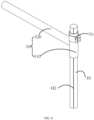
- one of the horizontal reference rod 50 and the second connecting rod is provided with a first arc-shaped scale, and the other is provided with a first reference indication line O2.
- the moving part 510 is provided with the first arc-shaped scale
- the second connecting rod 40 is provided with the first reference indication line O2 (the first reference indication line O2 can be a straight line located on the outer surface of the second connecting rod 40 and extend from the top of the second connecting rod to the bottom of the second connecting rod, as shown in Fig. 6 ) so that when the horizontal reference rod 50 is rotated relative to the second connecting rod 40, the angle at which the horizontal reference rod 50 is rotated can be known according to the first reference indication line O2 and the first arc-shaped scale on the moving part.
- a distance scale is provided on the first reference indication line O2 so that when the horizontal reference rod 50 slides relative to the second connecting rod 40, the distance that the horizontal reference rod 50 slides can be known according to the distance scale on the first reference indication line O2.
- the first reference indication line O2 may also be provided on the moving part.
- the second connecting rod 40 is provided with an arc scale, which extends from the top of the second connecting rod to the bottom of the second connecting rod for easy observation.
- the horizontal angle of the laser device 60 relative to the first connecting rod 30 can be adjusted by the movement of the horizontal reference rod 50 relative to the second connecting rod 40.
- the laser device 60 is movably installed on the horizontal reference rod 50.
- the laser device 60 is movably installed on the horizontal reference rod 50, meaning that the laser device 60 is horizontally rotatable relative to the horizontal reference rod 50.
- the laser device 60 may be rotated horizontally relative to the horizontal reference rod 50, and the positioning assist device further includes a second locking mechanism 80 for locking the laser device 60 relative to the horizontal reference rod 50 to limit the movement (e.g. horizontal rotation) of the laser device 60 relative to the horizontal reference rod 50.
- a second locking mechanism 80 for locking the laser device 60 relative to the horizontal reference rod 50 to limit the movement (e.g. horizontal rotation) of the laser device 60 relative to the horizontal reference rod 50.
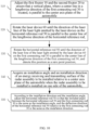
- the second locking mechanism 80 comprises a locking plate 81, a second locking bolt 82, and a second locking nut.
- the locking plate 81 is connected to the laser device 60, the locking plate 81 is perpendicular to the center axis plane of the automobile, the locking plate 81 is provided with an arc-shaped hole 811 for the second locking bolt 82 to pass through, and the horizontal reference rod 50 is provided with a sliding groove 530 for the second locking bolt 82 to pass through; the second locking bolt 82 is slidable along the sliding groove 530 provided along the lengthwise direction of the horizontal reference rod 50, and the second locking nut is used for cooperating with the second locking bolt 82 after the second locking bolt 82 passes through the arc-shaped hole 811 and the sliding groove 530.
- the second locking bolt 82 can slide along the arc direction of the arc-shaped hole 811, and the sum of the radians of the arc-shaped hole 811 is greater than or equal to 180 degrees, so that the horizontal angle of the laser device 60 relative to the horizontal reference rod 50 can be adjusted by the second locking bolt 82 sliding along the arc direction of the arc-shaped hole 811.
- the locking of the laser device 60 relative to the horizontal reference rod 50 can be achieved when the second locking nut is tightened, and the second locking nut is loosened when the laser device 60 needs to be rotated horizontally relative to the horizontal reference rod 50.
- connection of the laser device 60 to the locking plate 81 may be a fixed connection or a movable connection.
- the laser device 60 being fixedly connected to the locking plate 81, or the laser device 60 being movably connected to the locking plate 81, e.g. hinged.
- the laser device is movably connected (e.g. hinged) to the locking plate 81, the laser device can move relative to the locking plate 81 under an external force.
- the arc-shaped hole 811 is provided with a second arc-shaped scale
- the second locking bolt 82 is provided with a second reference indication line
- the horizontal angle of rotation of the laser device 60 relative to the horizontal reference rod 50 can be known through the second arc-shaped scale of the arc-shaped hole 811 and the second reference indication line.
- the laser device 60 can also slide along the lengthwise direction of the horizontal reference rod 50; in order to limit the laser device 60 to slide along other directions, the rotating part 520 of the horizontal reference rod 50 is of a square structure, the locking plate 81 is parallel to the top surface of the rotating part 520, the rotating part 520 is sleeved with a sliding block 90, the sliding block 90 can slide along the lengthwise direction of the horizontal reference rod 50, the sliding block 90 is provided with a second via hole through which the second locking bolt 82 passes, and the second locking bolt passes through the arc-shaped hole, the second via hole, and the sliding groove 530, and then cooperates with the second locking nut.
- the second locking nut is tightened, the locking plate 81 and the sliding block 90 remain relatively fixed, and the sliding block 90 can drive the second locking device 80 and the laser device 60 to slide along the lengthwise direction of the horizontal reference rod 50.
- one of the side of the horizontal reference rod and one side of the sliding block opposite the side of the horizontal reference is provided with a convex rib and the other is provided with a groove for receiving the convex rib.
- the convex rib can slide along the groove.
- sliding block 80 can only slide along the lengthwise direction of the horizontal reference rod under an external force.
- the locking plate 81 may be omitted.
- the second locking mechanism 80 comprises a second locking bolt 82 and a second locking nut
- the laser device 60 is installed on the second locking bolt 82
- the second locking bolt passes through the second via hole and the sliding groove 530 and then cooperates with the second locking nut
- the horizontal angle of the laser device 60 relative to the horizontal reference rod 50 can be adjusted by rotating the second locking bolt.
- one of the second locking bolt 82 and the sliding block 90 is provided with a second arc-shaped scale and the other is provided with a second reference indication line.
- the laser device 60 may be movably or fixedly installed on the second locking bolt 82.
- the laser device 60 can slide along the horizontal reference rod 50 in order to enable the laser light emitted by the laser device 60 to form a laser line on the first connecting rod 30, so as to prevent the laser line from being formed on the first connecting rod 30 due to the shielding of the horizontal reference rod 50 when the laser device 60 emits laser light downward.
- the length of the first connecting rod is longer than the length of the rotating part 520 of the horizontal reference rod 50.
- the mechanism by which the laser device 60 moves and locks relative to the horizontal reference rod 50 is not limited to the embodiments of the present application, and that other mechanisms that enable the laser device to move and lock relative to the horizontal reference rod are included in the embodiments of the present application.
- the side position of the radar assembly to be installed on one side of the automobile can be determined, namely, the angle of the energy receiving and transmitting surface of the radar assembly relative to one side of the automobile is determined.
- the sliding block 90 can be slid according to the requirements.
- embodiments of the present application provide a positioning assist method including the above-described positioning assist device for assisting in the installation of the above-described radar assembly to be installed.
- Step S10 adjust the first fixator 10 and the second fixator 20 to ensure that a vertical plane, where a center line in a lengthwise direction of the first connecting rod 30 is located, is parallel to the center axis plane of the automobile.
- Step S20 rotate the laser device 60 until the direction of the laser line of the laser light emitted by the laser device on the horizontal reference rod 50 is parallel to the center line of the lengthwise direction of the horizontal reference rod.
- Step S30 rotate the horizontal reference rod 50 until the direction of the laser line of the laser light emitted by the laser device 60 on the first connecting rod 30 is parallel to the center line of the lengthwise direction of the first connecting rod 30, and denote this position as a zero point position.
- Step S40 acquire an installation angle and an installation direction of an energy receiving and transmitting surface of the radar assembly to be installed relative to a center axis plane of the automobile when the radar assembly to be installed is installed on one side of the automobile.
- the installation angle of an energy receiving and transmitting surface of the radar assembly to be installed relative to a center axis plane of the automobile refers to a horizontal angle of the laser device 60 relative to the first connecting rod 30.
- the installation direction of an energy receiving and transmitting surface of the radar assembly to be installed relative to a center axis plane of the automobile refers to the deflection direction of the laser device relative to the first connecting rod.
- the horizontal angle of the laser device 60 relative to the first connecting rod 30 is an angle between the direction of the laser line emitted by the laser device and a center line O1 along the lengthwise direction of the first connecting rod in a horizontal plane where the center line along the lengthwise direction of the first connecting rod 30 is located.
- Step S50 according to the installation direction and the installation angle, adjust the horizontal reference rod 50 so that the included angle between the horizontal reference rod 50 and the first connecting rod 30 is the same as the installation angle, and the deflection direction of the horizontal reference rod 50 relative to the first connecting rod 30 is the same as the installation direction.
- first connecting rod 30 and the adjusted horizontal reference rod 50 are used to assist in installing the radar assembly to be installed.
- the step of according to the installation direction and the installation angle, adjusting the horizontal reference rod 50 so that the included angle between the horizontal reference rod 50 and the first connecting rod is the same as the installation angle further includes:
- Embodiments of the present invention provide a positioning assist device and method for determining the installation position of a radar assembly to be installed on a side surface of one side of an automobile by adjusting the laser device and the horizontal reference rod.
- the operation is simple, convenient, and fast, and the installation precision is high.
Landscapes
- Engineering & Computer Science (AREA)
- Physics & Mathematics (AREA)
- Radar, Positioning & Navigation (AREA)
- Remote Sensing (AREA)
- General Physics & Mathematics (AREA)
- Mechanical Engineering (AREA)
- Computer Networks & Wireless Communication (AREA)
- Electromagnetism (AREA)
- Optical Radar Systems And Details Thereof (AREA)
Claims (15)
- Positionierungshilfsvorrichtung, die dadurch gekennzeichnet ist, dass sie Folgendes umfasst:einen ersten Fixator (10), der an einem Vorderrad auf einer Seite eines Kraftfahrzeugs installiert ist;einen zweiten Fixator (20), der an einem Hinterrad auf einer Seite des Kraftfahrzeugs installiert ist, wobei sich der erste Fixator (10) und der zweite Fixator (20) auf einer selben Seite des Kraftfahrzeugs befinden;eine erste Verbindungsstange (30), die zwischen dem ersten Fixator (10) und dem zweiten Fixator (20) verbunden ist, wobei eine vertikale Ebene, in der sich eine Mittellinie (01) in einer Längsrichtung der ersten Verbindungsstange (30) befindet, parallel zu einer Mittelachsebene des Kraftfahrzeugs verläuft;eine zweite Verbindungsstange (40), die senkrecht zur ersten Verbindungsstange (30) angeordnet ist;eine horizontale Referenzstange (50), die an der zweiten Verbindungsstange (40) installiert und um die zweite Verbindungsstange (40) drehbar ist, wobei eine horizontale Ebene, in der sich die Mittellinie in der Längsrichtung der horizontalen Referenzstange (50) befindet, senkrecht zur horizontalen Ebene verläuft, in der sich die Mittellinie (01) in der Längsrichtung der ersten Verbindungsstange (30) befindet;und eine Laservorrichtung (60), die an der horizontalen Referenzstange (50) bewegbar installiert ist, wobei die Laservorrichtung (60) zum Emittieren von Laserlicht nach unten verwendet wird, um auf einem Objekt, das sich unter der Laservorrichtung (60) befindet, eine Laserlinie zu bilden, und wobei ein horizontaler Winkel der Laservorrichtung (60) relativ zur ersten Verbindungsstange (30) derart einstellbar ist, dass er ein Winkel einer Energieempfangs- und -übertragungsfläche einer Radaranordnung relativ zur Mittelachsebene des Kraftfahrzeugs ist, die zu installieren ist, wenn die zu installierende Radanordnung auf einer Seite des Kraftfahrzeugs installiert ist, wobei der horizontale Winkel der Laservorrichtung (60) relativ zur ersten Verbindungsstange (30) der Winkel zwischen einer Richtung der Laserlinie, die von der Laservorrichtung (60) emittiert wird, und der Mittellinie entlang der Längsrichtung der ersten Verbindungsstange (30) in der horizontalen Ebene ist, in der sich die Mittellinie (01) entlang der Längsrichtung der ersten Verbindungsstange (30) befindet.
- Positionierungshilfsvorrichtung nach Anspruch 1, dadurch gekennzeichnet, dass die Laservorrichtung relativ zur horizontalen Referenzstange horizontal drehbar ist.
- Positionierungshilfsvorrichtung nach Anspruch 2, dadurch gekennzeichnet, dass die Laservorrichtung entlang der Mittellinie in der Längsrichtung der horizontalen Referenzstange gleiten kann.
- Positionierungshilfsvorrichtung nach Anspruch 1, dadurch gekennzeichnet, dass die horizontale Referenzstange relativ zur zweiten Verbindungsstange entlang der Längsrichtung der zweiten Verbindungsstange gleitbar ist.
- Positionierungshilfsvorrichtung nach Anspruch 4, dadurch gekennzeichnet, dass die horizontale Referenzstange ein Bewegungsteil und ein Drehteil, das sich vertikal vom Bewegungsteil erstreckt, umfasst, das Bewegungsteil auf die zweite Verbindungsstange aufgehülst ist, das Bewegungsteil relativ zur zweiten Verbindungsstange entlang der Längsrichtung der zweiten Verbindungsstange gleiten kann, das Bewegungsteil sich relativ zur zweiten Verbindungsstange drehen kann und die Laservorrichtung am Drehteil bewegbar installiert ist.
- Positionierungshilfsvorrichtung nach Anspruch 5, dadurch gekennzeichnet, dass die Positionierungshilfsvorrichtung einen ersten Verriegelungsmechanismus umfasst, wobei der erste Verriegelungsmechanismus die horizontale Referenzstange relativ zur zweiten Verbindungsstange verriegeln kann, um eine Bewegung der horizontalen Referenzstange relativ zur zweiten Verbindungsstange zu begrenzen.
- Positionierungshilfsvorrichtung nach Anspruch 6, dadurch gekennzeichnet, dassder erste Verriegelungsmechanismus einen Verriegelungsring, einen ersten Schließbolzen und eine erste Gegenmutter umfasst;zwei Enden des Verriegelungsrings mit einem ersten Durchgangsloch und einer ersten Durchgangsbohrung versehen sind, durch die der erste Schließbolzen geführt wird, wobei der erste Verriegelungsring auf das Bewegungsteil aufgehülst ist und die erste Gegenmutter zum Zusammenwirken mit dem ersten Schließbolzen verwendet wird, nachdem der erste Schließbolzen durch das erste Durchgangsloch und die erste Durchgangsbohrung geführt ist.
- Positionierungshilfsvorrichtung nach Anspruch 1, dadurch gekennzeichnet, dass
an einer Verbindungsstelle der horizontalen Referenzstange und der zweiten Verbindungsstange eine der horizontalen Referenzstange und der zweiten Verbindungsstange mit einer ersten bogenförmigen Skala versehen ist und die andere mit einer ersten Referenzanzeigelinie versehen ist. - Positionierungshilfsvorrichtung nach Anspruch 3, dadurch gekennzeichnet, dass
die Positionierungshilfsvorrichtung ferner einen zweiten Verriegelungsmechanismus zum Verriegeln der Laservorrichtung relativ zur horizontalen Referenzstange umfasst, um eine Bewegung der Laservorrichtung relativ zur horizontalen Referenzstange zu begrenzen. - Positionierungshilfsvorrichtung nach Anspruch 9, dadurch gekennzeichnet, dassder zweite Verriegelungsmechanismus eine Verriegelungsplatte, einen zweiten Schließbolzen und eine zweite Gegenmutter umfasst, wobei die Verriegelungsplatte an der Laservorrichtung fixiert ist, die Verriegelungsplatte mit einem bogenförmigen Loch versehen ist, durch das der zweite Schließbolzen geführt wird, die horizontale Referenzstange mit einer Gleitnut versehen ist, durch die der zweite Schließbolzen geführt wird, und die zweite Gegenmutter zum Zusammenwirken mit dem zweiten Schließbolzen verwendet wird, nachdem der zweite Schließbolzen durch das bogenförmige Loch und die Gleitnut geführt wurde;wobei der zweite Bolzen in einer Bogenrichtung des bogenförmigen Lochs gleiten kann und eine Summe von Bogenmaßen der bogenförmigen Löcher größer als oder gleich 180 Grad ist.
- Positionierungshilfsvorrichtung nach Anspruch 10, dadurch gekennzeichnet, dassein Gleitblock auf die horizontale Referenzstange aufgehülst ist, der Gleitblock entlang der Längsrichtung der horizontalen Referenzstange gleiten kann, ein zweites Durchgangsloch, durch das der zweite Schließbolzen geführt wird, am Gleitblock vorgesehen ist und der zweite Schließbolzen mit der zweiten Gegenmutter zusammenwirkt, nachdem er durch das bogenförmige Loch, das zweite Durchgangsloch und die Gleitnut geführt wurde;wobei die zweite Gegenmutter am Gleitblock anliegt, wenn die zweite Gegenmutter festgezogen ist.
- Positionierungshilfsvorrichtung nach Anspruch 10, dadurch gekennzeichnet, dass
am bogenförmigen Loch eine zweite bogenförmige Skala bereitgestellt ist und am zweiten Schließbolzen eine zweite Referenzanzeigelinie bereitgestellt ist. - Positionierungshilfsvorrichtung nach Anspruch 1, dadurch gekennzeichnet, dassder erste Fixator einen ersten Installationssitz und zwei erste Klauenanordnungen umfasst, wobei die zwei ersten Klauenanordnungen an eine Nabe des Vorderrads geklemmt sind, der erste Installationssitz sich in Mittenpositionen der zwei ersten Klauenanordnungen befindet und ein erstes Ende der ersten Fixierstange auf dem ersten Installationssitz installiert ist;der zweite Fixator einen zweiten Installationssitz und zwei zweite Klauenanordnungen umfasst, wobei sich der zweite Installationssitz in Mittenpositionen der zweiten Klauenanordnungen befindet, die zweiten Klauenanordnungen an die Nabe des Hinterrads geklemmt sind und ein zweites Ende der ersten Fixierstange auf dem zweiten Installationssitz installiert ist.
- Positionierungshilfsverfahren, das die Positionierungshilfsvorrichtung nach einem der Ansprüche 1 bis 13 umfasst, dadurch gekennzeichnet, dass das Verfahren Folgendes umfasst:Einstellen des ersten Fixators (10) und des zweiten Fixators (20), um sicherzustellen, dass die vertikale Ebene, in der sich die Mittellinie (01) in der Längsrichtung der ersten Verbindungsstange (30) befindet, parallel zur Mittelachsebene des Kraftfahrzeugs verläuft;Drehen der Laservorrichtung (60), bis die Richtung der Laserlinie eines Laserlichts, das von der Laservorrichtung (60) auf die horizontale Referenzstange (50) emittiert wird, parallel zur Mittellinie der Längsrichtung der horizontalen Referenzstange (50) verläuft;Drehen der horizontalen Referenzstange (50), bis die Richtung der Laserlinie des Laserlichts, das von der Laservorrichtung (60) auf die erste Verbindungsstange emittiert wird, parallel zur Mittellinie der Längsrichtung der ersten Verbindungsstange (30) verläuft; undKennzeichnen dieser Position als eine Nullpunktposition;Erfassen eines Installationswinkels und einer Installationsrichtung der Energieempfangs- und - übertragungsfläche der zu installierenden Radaranordnung relativ zur Mittelachsebene des Kraftfahrzeugs, wenn die zu installierende Radanordnung auf einer Seite des Kraftfahrzeugs installiert ist; undEinstellen der horizontalen Referenzstange (50) gemäß der Installationsrichtung und dem Installationswinkel derart, dass ein eingeschlossener Winkel zwischen der horizontalen Referenzstange (50) und der ersten Verbindungsstange (30) derselbe ist wie der Installationswinkel und eine Ablenkrichtung der horizontalen Referenzstange (50) relativ zur ersten Verbindungsstange (30) dieselbe ist wie die Installationsrichtung, wobei die erste Verbindungsstange (30) und die eingestellte horizontale Referenzstange (50) verwendet werden, um die Installation der zu installierenden Radaranordnung zu unterstützen.
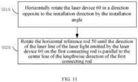
- Verfahren nach Anspruch 14, dadurch gekennzeichnet, dass es ferner Folgendes umfasst:
einen Schritt des Einstellens der horizontalen Referenzstange gemäß der Installationsrichtung und dem Installationswinkel derart, dass ein eingeschlossener Winkel zwischen der horizontalen Referenzstange und der ersten Verbindungsstange derselbe ist wie der Installationswinkel, das ferner Folgendes umfasst:horizontales Drehen der Laservorrichtung in eine Richtung, die der Installationsrichtung entgegengesetzt ist, um den Installationswinkel; undDrehen der horizontalen Referenzstange, bis die Richtung der Laserlinie des Laserlichts, das von der Laservorrichtung auf die erste Verbindungsstange emittiert wird, parallel zur Mittellinie der Längsrichtung der ersten Verbindungsstange verläuft.
Applications Claiming Priority (2)
| Application Number | Priority Date | Filing Date | Title |
|---|---|---|---|
| CN202110296223.7A CN112937458B (zh) | 2021-03-19 | 2021-03-19 | 一种辅助定位装置及定位方法 |
| PCT/CN2022/078626 WO2022193943A1 (zh) | 2021-03-19 | 2022-03-01 | 一种辅助定位装置及定位方法 |
Publications (3)
| Publication Number | Publication Date |
|---|---|
| EP4292884A1 EP4292884A1 (de) | 2023-12-20 |
| EP4292884A4 EP4292884A4 (de) | 2024-03-20 |
| EP4292884B1 true EP4292884B1 (de) | 2024-11-20 |
Family
ID=76227208
Family Applications (1)
| Application Number | Title | Priority Date | Filing Date |
|---|---|---|---|
| EP22770298.2A Active EP4292884B1 (de) | 2021-03-19 | 2022-03-01 | Positionierungshilfsvorrichtung und positionierungshilfsverfahren |
Country Status (4)
| Country | Link |
|---|---|
| US (1) | US12583398B2 (de) |
| EP (1) | EP4292884B1 (de) |
| CN (1) | CN112937458B (de) |
| WO (1) | WO2022193943A1 (de) |
Families Citing this family (5)
| Publication number | Priority date | Publication date | Assignee | Title |
|---|---|---|---|---|
| USD1072146S1 (en) * | 2020-10-28 | 2025-04-22 | S&P Collective, LLC | Target apparatus for firearms and archery |
| CN112937458B (zh) * | 2021-03-19 | 2025-04-04 | 深圳市道通科技股份有限公司 | 一种辅助定位装置及定位方法 |
| CN114114219B (zh) * | 2021-11-30 | 2025-11-25 | 深圳市道通科技股份有限公司 | 车载雷达标定设备及方法 |
| CN120651149B (zh) * | 2025-07-15 | 2025-12-02 | 中交路桥华南工程有限公司 | 一种小箱梁安装轴线偏差实时监测仪 |
| CN121252695A (zh) * | 2025-10-30 | 2026-01-02 | 太仓戴尔塔精密科技有限公司 | 一种带手柄的穿刺针轴线准直偏心度测量设备 |
Family Cites Families (12)
| Publication number | Priority date | Publication date | Assignee | Title |
|---|---|---|---|---|
| US4330945A (en) * | 1980-03-31 | 1982-05-25 | Kansas Jack, Inc. | Vehicle frame and body alignment apparatus |
| SE459615B (sv) | 1986-10-01 | 1989-07-17 | Torgny Hoervallius | Saett och anordning foer uppmaetning av hjulvinklar i ett motorfordons framvagn |
| FR2825157B1 (fr) | 2001-05-23 | 2006-02-17 | Renault | Dispositif de verification de l'alignement d'un radar de vehicule automobile |
| US6809806B1 (en) | 2003-05-27 | 2004-10-26 | International Truck Intellectual Property Company, Llc | Apparatus and method for verifying the beam axis of front-looking land vehicle transceiver antenna |
| CN106772320B (zh) * | 2017-03-10 | 2023-06-16 | 中国科学技术大学 | 一种激光雷达的发射光束方向初步调整垂直装置 |
| CN108051815B (zh) * | 2017-12-07 | 2023-11-07 | 上海为彪汽配制造有限公司 | 一种装设毫米波雷达的汽车和安装该毫米波雷达的方法、组件 |
| CN210139827U (zh) | 2019-04-30 | 2020-03-13 | 深圳森云智能科技有限公司 | 一种变道辅助系统安装装置 |
| US12158358B2 (en) * | 2019-09-23 | 2024-12-03 | Christopher Dennis Gilliand | Vehicle leveling device and method |
| CN111830474B (zh) * | 2020-07-23 | 2023-04-21 | 烟台开发区海德科技有限公司 | 汽车后雷达标定装置的定位装置及方法 |
| CN112045602B (zh) * | 2020-09-21 | 2024-12-06 | 深圳市道通科技股份有限公司 | 一种轮毂夹持装置 |
| CN112937458B (zh) | 2021-03-19 | 2025-04-04 | 深圳市道通科技股份有限公司 | 一种辅助定位装置及定位方法 |
| CN215552899U (zh) * | 2021-03-19 | 2022-01-18 | 深圳市道通科技股份有限公司 | 一种辅助定位装置 |
-
2021
- 2021-03-19 CN CN202110296223.7A patent/CN112937458B/zh active Active
-
2022
- 2022-03-01 WO PCT/CN2022/078626 patent/WO2022193943A1/zh not_active Ceased
- 2022-03-01 US US18/282,546 patent/US12583398B2/en active Active
- 2022-03-01 EP EP22770298.2A patent/EP4292884B1/de active Active
Also Published As
| Publication number | Publication date |
|---|---|
| US12583398B2 (en) | 2026-03-24 |
| US20240157888A1 (en) | 2024-05-16 |
| CN112937458A (zh) | 2021-06-11 |
| CN112937458B (zh) | 2025-04-04 |
| EP4292884A1 (de) | 2023-12-20 |
| WO2022193943A1 (zh) | 2022-09-22 |
| EP4292884A4 (de) | 2024-03-20 |
Similar Documents
| Publication | Publication Date | Title |
|---|---|---|
| EP4292884B1 (de) | Positionierungshilfsvorrichtung und positionierungshilfsverfahren | |
| TWI449260B (zh) | 用來調整轉動角度之調整機構及其天線系統 | |
| CN111997992B (zh) | 锁紧装置 | |
| US11631929B2 (en) | Fastening device and associated method | |
| CN111442745A (zh) | 一种摆正校准设备的装置及方法 | |
| CN112161589B (zh) | 车辆标定设备 | |
| CN207773038U (zh) | 毫米波雷达的安装结构以及具有其的车辆 | |
| US20090113732A1 (en) | Apparatus and Method for Theodolite Support | |
| WO2020013898A1 (en) | Orientation adjustable mounts and related methods of locking into alignment | |
| CN112161590B (zh) | 车辆对中装置及车辆标定设备 | |
| CN215552899U (zh) | 一种辅助定位装置 | |
| CN214750805U (zh) | 一种测试装置 | |
| CN106838595A (zh) | 折弯机专用多点安全光幕 | |
| CN110658523B (zh) | 一种车载雷达安装校准装置及校准方法 | |
| US20230175661A1 (en) | Displacement System for Simultaneous Displacement of Light Modules of Lighting Apparatus for Motor Vehicle | |
| CN115016089B (zh) | 一种用于分体积木反射式风洞纹影仪的光路快速找准方法 | |
| CN111601642B (zh) | 一种调节机构、光距尺系统和医疗设备 | |
| CN111982059A (zh) | 适用于2d激光测量仪的激光器调整机构及调整方法 | |
| CN114079711B (zh) | 线阵相机激光补光共线调整装置和调整方法 | |
| CN208827989U (zh) | 一种前桥总成装配转向角检测调整夹具 | |
| CN109774958B (zh) | 一种勘测无人机 | |
| CN115561871B (zh) | 一种光学镜片装调装置及其调整方法 | |
| CN119620213A (zh) | 射线检查系统 | |
| CN114114219B (zh) | 车载雷达标定设备及方法 | |
| CN216013641U (zh) | 一种标定车载雷达与摄像头的装置 |
Legal Events
| Date | Code | Title | Description |
|---|---|---|---|
| STAA | Information on the status of an ep patent application or granted ep patent |
Free format text: STATUS: THE INTERNATIONAL PUBLICATION HAS BEEN MADE |
|
| PUAI | Public reference made under article 153(3) epc to a published international application that has entered the european phase |
Free format text: ORIGINAL CODE: 0009012 |
|
| STAA | Information on the status of an ep patent application or granted ep patent |
Free format text: STATUS: REQUEST FOR EXAMINATION WAS MADE |
|
| 17P | Request for examination filed |
Effective date: 20230913 |
|
| AK | Designated contracting states |
Kind code of ref document: A1 Designated state(s): AL AT BE BG CH CY CZ DE DK EE ES FI FR GB GR HR HU IE IS IT LI LT LU LV MC MK MT NL NO PL PT RO RS SE SI SK SM TR |
|
| REG | Reference to a national code |
Ref country code: DE Ref legal event code: R079 Free format text: PREVIOUS MAIN CLASS: B60R0011000000 Ipc: G01B0011270000 Ref document number: 602022007999 Country of ref document: DE |
|
| A4 | Supplementary search report drawn up and despatched |
Effective date: 20240219 |
|
| RIC1 | Information provided on ipc code assigned before grant |
Ipc: G01S 7/40 20060101ALI20240213BHEP Ipc: G01S 13/931 20200101ALI20240213BHEP Ipc: G01B 11/27 20060101AFI20240213BHEP |
|
| RAP3 | Party data changed (applicant data changed or rights of an application transferred) |
Owner name: AUTEL INTELLIGENT TECHNOLOGY CORP. LTD. |
|
| DAV | Request for validation of the european patent (deleted) | ||
| DAX | Request for extension of the european patent (deleted) | ||
| GRAP | Despatch of communication of intention to grant a patent |
Free format text: ORIGINAL CODE: EPIDOSNIGR1 |
|
| STAA | Information on the status of an ep patent application or granted ep patent |
Free format text: STATUS: GRANT OF PATENT IS INTENDED |
|
| INTG | Intention to grant announced |
Effective date: 20240719 |
|
| GRAS | Grant fee paid |
Free format text: ORIGINAL CODE: EPIDOSNIGR3 |
|
| GRAA | (expected) grant |
Free format text: ORIGINAL CODE: 0009210 |
|
| STAA | Information on the status of an ep patent application or granted ep patent |
Free format text: STATUS: THE PATENT HAS BEEN GRANTED |
|
| AK | Designated contracting states |
Kind code of ref document: B1 Designated state(s): AL AT BE BG CH CY CZ DE DK EE ES FI FR GB GR HR HU IE IS IT LI LT LU LV MC MK MT NL NO PL PT RO RS SE SI SK SM TR |
|
| REG | Reference to a national code |
Ref country code: GB Ref legal event code: FG4D |
|
| REG | Reference to a national code |
Ref country code: CH Ref legal event code: EP |
|
| REG | Reference to a national code |
Ref country code: DE Ref legal event code: R096 Ref document number: 602022007999 Country of ref document: DE |
|
| REG | Reference to a national code |
Ref country code: IE Ref legal event code: FG4D |
|
| REG | Reference to a national code |
Ref country code: LT Ref legal event code: MG9D |
|
| REG | Reference to a national code |
Ref country code: NL Ref legal event code: MP Effective date: 20241120 |
|
| PG25 | Lapsed in a contracting state [announced via postgrant information from national office to epo] |
Ref country code: IS Free format text: LAPSE BECAUSE OF FAILURE TO SUBMIT A TRANSLATION OF THE DESCRIPTION OR TO PAY THE FEE WITHIN THE PRESCRIBED TIME-LIMIT Effective date: 20250320 Ref country code: PT Free format text: LAPSE BECAUSE OF FAILURE TO SUBMIT A TRANSLATION OF THE DESCRIPTION OR TO PAY THE FEE WITHIN THE PRESCRIBED TIME-LIMIT Effective date: 20250320 Ref country code: HR Free format text: LAPSE BECAUSE OF FAILURE TO SUBMIT A TRANSLATION OF THE DESCRIPTION OR TO PAY THE FEE WITHIN THE PRESCRIBED TIME-LIMIT Effective date: 20241120 |
|
| PGFP | Annual fee paid to national office [announced via postgrant information from national office to epo] |
Ref country code: DE Payment date: 20250319 Year of fee payment: 4 |
|
| PG25 | Lapsed in a contracting state [announced via postgrant information from national office to epo] |
Ref country code: FI Free format text: LAPSE BECAUSE OF FAILURE TO SUBMIT A TRANSLATION OF THE DESCRIPTION OR TO PAY THE FEE WITHIN THE PRESCRIBED TIME-LIMIT Effective date: 20241120 Ref country code: NL Free format text: LAPSE BECAUSE OF FAILURE TO SUBMIT A TRANSLATION OF THE DESCRIPTION OR TO PAY THE FEE WITHIN THE PRESCRIBED TIME-LIMIT Effective date: 20241120 |
|
| REG | Reference to a national code |
Ref country code: AT Ref legal event code: MK05 Ref document number: 1743918 Country of ref document: AT Kind code of ref document: T Effective date: 20241120 |
|
| PG25 | Lapsed in a contracting state [announced via postgrant information from national office to epo] |
Ref country code: BG Free format text: LAPSE BECAUSE OF FAILURE TO SUBMIT A TRANSLATION OF THE DESCRIPTION OR TO PAY THE FEE WITHIN THE PRESCRIBED TIME-LIMIT Effective date: 20241120 |
|
| PG25 | Lapsed in a contracting state [announced via postgrant information from national office to epo] |
Ref country code: ES Free format text: LAPSE BECAUSE OF FAILURE TO SUBMIT A TRANSLATION OF THE DESCRIPTION OR TO PAY THE FEE WITHIN THE PRESCRIBED TIME-LIMIT Effective date: 20241120 |
|
| PG25 | Lapsed in a contracting state [announced via postgrant information from national office to epo] |
Ref country code: NO Free format text: LAPSE BECAUSE OF FAILURE TO SUBMIT A TRANSLATION OF THE DESCRIPTION OR TO PAY THE FEE WITHIN THE PRESCRIBED TIME-LIMIT Effective date: 20250220 |
|
| PG25 | Lapsed in a contracting state [announced via postgrant information from national office to epo] |
Ref country code: GR Free format text: LAPSE BECAUSE OF FAILURE TO SUBMIT A TRANSLATION OF THE DESCRIPTION OR TO PAY THE FEE WITHIN THE PRESCRIBED TIME-LIMIT Effective date: 20250221 Ref country code: AT Free format text: LAPSE BECAUSE OF FAILURE TO SUBMIT A TRANSLATION OF THE DESCRIPTION OR TO PAY THE FEE WITHIN THE PRESCRIBED TIME-LIMIT Effective date: 20241120 Ref country code: LV Free format text: LAPSE BECAUSE OF FAILURE TO SUBMIT A TRANSLATION OF THE DESCRIPTION OR TO PAY THE FEE WITHIN THE PRESCRIBED TIME-LIMIT Effective date: 20241120 |
|
| PG25 | Lapsed in a contracting state [announced via postgrant information from national office to epo] |
Ref country code: PL Free format text: LAPSE BECAUSE OF FAILURE TO SUBMIT A TRANSLATION OF THE DESCRIPTION OR TO PAY THE FEE WITHIN THE PRESCRIBED TIME-LIMIT Effective date: 20241120 |
|
| PGFP | Annual fee paid to national office [announced via postgrant information from national office to epo] |
Ref country code: FR Payment date: 20250324 Year of fee payment: 4 |
|
| PG25 | Lapsed in a contracting state [announced via postgrant information from national office to epo] |
Ref country code: RS Free format text: LAPSE BECAUSE OF FAILURE TO SUBMIT A TRANSLATION OF THE DESCRIPTION OR TO PAY THE FEE WITHIN THE PRESCRIBED TIME-LIMIT Effective date: 20250220 |
|
| PG25 | Lapsed in a contracting state [announced via postgrant information from national office to epo] |
Ref country code: SM Free format text: LAPSE BECAUSE OF FAILURE TO SUBMIT A TRANSLATION OF THE DESCRIPTION OR TO PAY THE FEE WITHIN THE PRESCRIBED TIME-LIMIT Effective date: 20241120 |
|
| PG25 | Lapsed in a contracting state [announced via postgrant information from national office to epo] |
Ref country code: DK Free format text: LAPSE BECAUSE OF FAILURE TO SUBMIT A TRANSLATION OF THE DESCRIPTION OR TO PAY THE FEE WITHIN THE PRESCRIBED TIME-LIMIT Effective date: 20241120 |
|
| PG25 | Lapsed in a contracting state [announced via postgrant information from national office to epo] |
Ref country code: EE Free format text: LAPSE BECAUSE OF FAILURE TO SUBMIT A TRANSLATION OF THE DESCRIPTION OR TO PAY THE FEE WITHIN THE PRESCRIBED TIME-LIMIT Effective date: 20241120 |
|
| PG25 | Lapsed in a contracting state [announced via postgrant information from national office to epo] |
Ref country code: RO Free format text: LAPSE BECAUSE OF FAILURE TO SUBMIT A TRANSLATION OF THE DESCRIPTION OR TO PAY THE FEE WITHIN THE PRESCRIBED TIME-LIMIT Effective date: 20241120 |
|
| PG25 | Lapsed in a contracting state [announced via postgrant information from national office to epo] |
Ref country code: SK Free format text: LAPSE BECAUSE OF FAILURE TO SUBMIT A TRANSLATION OF THE DESCRIPTION OR TO PAY THE FEE WITHIN THE PRESCRIBED TIME-LIMIT Effective date: 20241120 |
|
| PG25 | Lapsed in a contracting state [announced via postgrant information from national office to epo] |
Ref country code: CZ Free format text: LAPSE BECAUSE OF FAILURE TO SUBMIT A TRANSLATION OF THE DESCRIPTION OR TO PAY THE FEE WITHIN THE PRESCRIBED TIME-LIMIT Effective date: 20241120 |
|
| PG25 | Lapsed in a contracting state [announced via postgrant information from national office to epo] |
Ref country code: IT Free format text: LAPSE BECAUSE OF FAILURE TO SUBMIT A TRANSLATION OF THE DESCRIPTION OR TO PAY THE FEE WITHIN THE PRESCRIBED TIME-LIMIT Effective date: 20241120 |
|
| REG | Reference to a national code |
Ref country code: DE Ref legal event code: R097 Ref document number: 602022007999 Country of ref document: DE |
|
| PG25 | Lapsed in a contracting state [announced via postgrant information from national office to epo] |
Ref country code: SE Free format text: LAPSE BECAUSE OF FAILURE TO SUBMIT A TRANSLATION OF THE DESCRIPTION OR TO PAY THE FEE WITHIN THE PRESCRIBED TIME-LIMIT Effective date: 20241120 |
|
| PLBE | No opposition filed within time limit |
Free format text: ORIGINAL CODE: 0009261 |
|
| STAA | Information on the status of an ep patent application or granted ep patent |
Free format text: STATUS: NO OPPOSITION FILED WITHIN TIME LIMIT |
|
| PG25 | Lapsed in a contracting state [announced via postgrant information from national office to epo] |
Ref country code: MC Free format text: LAPSE BECAUSE OF FAILURE TO SUBMIT A TRANSLATION OF THE DESCRIPTION OR TO PAY THE FEE WITHIN THE PRESCRIBED TIME-LIMIT Effective date: 20241120 |
|
| 26N | No opposition filed |
Effective date: 20250821 |
|
| REG | Reference to a national code |
Ref country code: CH Ref legal event code: H13 Free format text: ST27 STATUS EVENT CODE: U-0-0-H10-H13 (AS PROVIDED BY THE NATIONAL OFFICE) Effective date: 20251023 |
|
| PG25 | Lapsed in a contracting state [announced via postgrant information from national office to epo] |
Ref country code: LU Free format text: LAPSE BECAUSE OF NON-PAYMENT OF DUE FEES Effective date: 20250301 |
|
| REG | Reference to a national code |
Ref country code: BE Ref legal event code: MM Effective date: 20250331 |
|
| PG25 | Lapsed in a contracting state [announced via postgrant information from national office to epo] |
Ref country code: BE Free format text: LAPSE BECAUSE OF NON-PAYMENT OF DUE FEES Effective date: 20250331 |
|
| PG25 | Lapsed in a contracting state [announced via postgrant information from national office to epo] |
Ref country code: CH Free format text: LAPSE BECAUSE OF NON-PAYMENT OF DUE FEES Effective date: 20250331 |
|
| PG25 | Lapsed in a contracting state [announced via postgrant information from national office to epo] |
Ref country code: IE Free format text: LAPSE BECAUSE OF NON-PAYMENT OF DUE FEES Effective date: 20250301 |