EP4289596A1 - Hybride ölelektrozitût-spritzgiessmaschine - Google Patents
Hybride ölelektrozitût-spritzgiessmaschine Download PDFInfo
- Publication number
- EP4289596A1 EP4289596A1 EP21929925.2A EP21929925A EP4289596A1 EP 4289596 A1 EP4289596 A1 EP 4289596A1 EP 21929925 A EP21929925 A EP 21929925A EP 4289596 A1 EP4289596 A1 EP 4289596A1
- Authority
- EP
- European Patent Office
- Prior art keywords
- injection
- feeding
- transmission
- screw rod
- plate
- Prior art date
- Legal status (The legal status is an assumption and is not a legal conclusion. Google has not performed a legal analysis and makes no representation as to the accuracy of the status listed.)
- Granted
Links
Images


Classifications
-
- B—PERFORMING OPERATIONS; TRANSPORTING
- B29—WORKING OF PLASTICS; WORKING OF SUBSTANCES IN A PLASTIC STATE IN GENERAL
- B29C—SHAPING OR JOINING OF PLASTICS; SHAPING OF MATERIAL IN A PLASTIC STATE, NOT OTHERWISE PROVIDED FOR; AFTER-TREATMENT OF THE SHAPED PRODUCTS, e.g. REPAIRING
- B29C45/00—Injection moulding, i.e. forcing the required volume of moulding material through a nozzle into a closed mould; Apparatus therefor
- B29C45/17—Component parts, details or accessories; Auxiliary operations
- B29C45/46—Means for plasticising or homogenising the moulding material or forcing it into the mould
- B29C45/47—Means for plasticising or homogenising the moulding material or forcing it into the mould using screws
- B29C45/50—Axially movable screw
- B29C45/5008—Drive means therefor
-
- B—PERFORMING OPERATIONS; TRANSPORTING
- B29—WORKING OF PLASTICS; WORKING OF SUBSTANCES IN A PLASTIC STATE IN GENERAL
- B29C—SHAPING OR JOINING OF PLASTICS; SHAPING OF MATERIAL IN A PLASTIC STATE, NOT OTHERWISE PROVIDED FOR; AFTER-TREATMENT OF THE SHAPED PRODUCTS, e.g. REPAIRING
- B29C45/00—Injection moulding, i.e. forcing the required volume of moulding material through a nozzle into a closed mould; Apparatus therefor
- B29C45/17—Component parts, details or accessories; Auxiliary operations
- B29C45/76—Measuring, controlling or regulating
- B29C45/82—Hydraulic or pneumatic circuits
-
- B—PERFORMING OPERATIONS; TRANSPORTING
- B29—WORKING OF PLASTICS; WORKING OF SUBSTANCES IN A PLASTIC STATE IN GENERAL
- B29C—SHAPING OR JOINING OF PLASTICS; SHAPING OF MATERIAL IN A PLASTIC STATE, NOT OTHERWISE PROVIDED FOR; AFTER-TREATMENT OF THE SHAPED PRODUCTS, e.g. REPAIRING
- B29C45/00—Injection moulding, i.e. forcing the required volume of moulding material through a nozzle into a closed mould; Apparatus therefor
- B29C45/17—Component parts, details or accessories; Auxiliary operations
- B29C2045/1784—Component parts, details or accessories not otherwise provided for; Auxiliary operations not otherwise provided for
- B29C2045/1792—Machine parts driven by an electric motor, e.g. electric servomotor
-
- B—PERFORMING OPERATIONS; TRANSPORTING
- B29—WORKING OF PLASTICS; WORKING OF SUBSTANCES IN A PLASTIC STATE IN GENERAL
- B29C—SHAPING OR JOINING OF PLASTICS; SHAPING OF MATERIAL IN A PLASTIC STATE, NOT OTHERWISE PROVIDED FOR; AFTER-TREATMENT OF THE SHAPED PRODUCTS, e.g. REPAIRING
- B29C45/00—Injection moulding, i.e. forcing the required volume of moulding material through a nozzle into a closed mould; Apparatus therefor
- B29C45/17—Component parts, details or accessories; Auxiliary operations
- B29C45/46—Means for plasticising or homogenising the moulding material or forcing it into the mould
- B29C45/47—Means for plasticising or homogenising the moulding material or forcing it into the mould using screws
- B29C45/50—Axially movable screw
- B29C45/5008—Drive means therefor
- B29C2045/504—Drive means therefor electric motors for rotary and axial movement of the screw being coaxial with the screw
-
- B—PERFORMING OPERATIONS; TRANSPORTING
- B29—WORKING OF PLASTICS; WORKING OF SUBSTANCES IN A PLASTIC STATE IN GENERAL
- B29C—SHAPING OR JOINING OF PLASTICS; SHAPING OF MATERIAL IN A PLASTIC STATE, NOT OTHERWISE PROVIDED FOR; AFTER-TREATMENT OF THE SHAPED PRODUCTS, e.g. REPAIRING
- B29C45/00—Injection moulding, i.e. forcing the required volume of moulding material through a nozzle into a closed mould; Apparatus therefor
- B29C45/17—Component parts, details or accessories; Auxiliary operations
- B29C45/46—Means for plasticising or homogenising the moulding material or forcing it into the mould
- B29C45/47—Means for plasticising or homogenising the moulding material or forcing it into the mould using screws
- B29C45/50—Axially movable screw
- B29C45/5008—Drive means therefor
- B29C2045/506—Drive means therefor using a hydraulic transmission between drive motor and the axially movable screw
-
- B—PERFORMING OPERATIONS; TRANSPORTING
- B29—WORKING OF PLASTICS; WORKING OF SUBSTANCES IN A PLASTIC STATE IN GENERAL
- B29C—SHAPING OR JOINING OF PLASTICS; SHAPING OF MATERIAL IN A PLASTIC STATE, NOT OTHERWISE PROVIDED FOR; AFTER-TREATMENT OF THE SHAPED PRODUCTS, e.g. REPAIRING
- B29C45/00—Injection moulding, i.e. forcing the required volume of moulding material through a nozzle into a closed mould; Apparatus therefor
- B29C45/17—Component parts, details or accessories; Auxiliary operations
- B29C45/76—Measuring, controlling or regulating
- B29C45/82—Hydraulic or pneumatic circuits
- B29C2045/824—Accumulators
Definitions
- the present invention belongs to the field of injection molding machine, specifically relates to an oil-electricity hybrid injection molding machine.
- each of the injection shaft and feeding shaft is controlled by a servo motor
- the injection motor drives the ball screw to rotate through the injection belt, push the screw rod forward and backward; when feeding, the feeding motor drives the screw rod to rotate, in this way, the injection and feeding each require a servo motor (usually the injection servo motor is larger than the feeding servo motor), and throughout the entire injection process, they do not simultaneously produce maximum torque to work (that is, when the output power of the injection motor is maximum, the feeding motor will not produce maximum output at the same time, and vice versa), so the utilization efficiency of the motor is relatively low. Therefore, not only the selection of servo motors increase the cost of injection molding machines, but also the low usage rate of servo motors leads to high injection molding costs.
- the technical problem to be solved by the present invention is to overcome the deficiencies of the conventional art, and to provide an improved oil-electricity hybrid injection molding machine.
- an oil-electricity hybrid injection molding machine comprising:
- the injection unit comprises an injection power component capable of pushing the screw rod to move along its length direction, an injection transmission component connecting the injection power component to the output shaft in a transmission manner, and the first clutch arranged on the output shaft and capable of disengaging and engaging the output shaft and the injection transmission component;
- the feeding unit comprises a feeding power component connected to the output shaft in a transmission manner and capable of driving the screw rod to rotate, a feeding transmission component connecting the feeding power component to the output shaft in a transmission manner, and the second clutch arranged on the output shaft and capable of disengaging and engaging the output shaft and the feeding transmission component.
- the injection or feeding process can be carried out by sharing a power motor.
- the feeding power component and the injection power component are arranged coaxially with the screw rod, and the feeding power component and the injection power component are rotatably arranged relative to each other.
- a servo motor only one power motor (a servo motor) can work to implement the injection molding of the screw rod, especially during injection molding, the maximum injection pressure is supplied by the servo motor and the auxiliary oil cylinder simultaneously, therefore, the specification of the servo motor is smaller than that of the servo motor of the all-electric injection molding output shaft, which not only reduces the cost of motor specification selection, but also reduces injection molding costs.
- an injection head plate, an injection second plate and an injection tail plate are formed on the base, wherein the feeding barrel and the injection head plate are fixedly connected, the injection second plate is slidably arranged on the base and capable of moving with the screw rod in its length direction, the power motor, the injection unit and the feeding unit are arranged on the injection second plate, and the auxiliary oil cylinder is arranged between the injection second plate and the injection tail plate.
- the installation of the power system has a compact structure, small volume, and easy implementation, and meanwhile, with the assistance of the auxiliary oil cylinder, it is convenient for the implementation of injection and processing, especially during injection, it can accelerate the injection speed of the screw rod at the point the energy accumulator releases energy.
- the feeding power component comprises a feeding transmission shaft coaxial with the screw rod and fixedly connected to the rear end portion of the screw rod, and a feeding belt wheel fixed on the feeding transmission shaft
- the feeding transmission component comprises a feeding transmission wheel connected to the output shaft through the second clutch, and a feeding transmission belt connecting the feeding belt wheel to the feeding transmission wheel in a transmission manner.
- the injection power component comprises an injection transmission shaft coaxial with and rotatably connected to the feeding transmission shaft, an injection belt wheel fixed on the injection transmission shaft, and a transmission lead screw fixedly connected to the injection transmission shaft, wherein the injection transmission shaft passes through the injection second plate and is rotatably arranged relative to the injection second plate, and the transmission lead screw is connected to the injection tail plate via a fixed plate, and the injection transmission component comprises an injection transmission wheel connected to the output shaft through the first clutch, and an injection transmission belt connecting the injection transmission wheel to the injection belt wheel in a transmission manner.
- the injection unit further comprises an encoder located inside the injection transmission belt and matched with the injection belt wheel and/or the injection transmission belt, and a pressure sensor arranged between the fixed plate and the injection tail plate.
- the movement status of the screw rod can be accurately controlled to facilitate the control of injection accuracy.
- the pressure sensor mainly obtains feedback on the screw rod pressure during injection molding and adjusts the injection process accordingly based on the feedback value.
- the feeding process is divided into:
- auxiliary oil cylinders located on opposite sides of the centerline of the screw rod.
- the synchronous movement of the two auxiliary oil cylinders ensures the speed and stability of the injection.
- the above-mentioned base comprises an injection table and pillars located on the injection table, wherein the injection table is square, with four pillars distributed at the four corners of the injection table, and the power system is arranged on the pillars through two injection pull rods extending along the length direction of the screw rod.
- each of the two injection pull rods passes through two pillars located on the same side, the injection head plate, the injection tail plate, and the injection second plate are located between the two injection pull rods, each of the injection pull rods sequentially crosses the injection head plate, the injection second plate, and the injection tail plate on the same side, wherein the injection second plate is slidably arranged on the injection pull rods, and the injection head plate and the injection tail plate are positioned on the injection pull rods are configured that the distance between the injection head plate and the injection tail plate remains unchanged.
- a first rod sleeve is arranged at one end portion of each of the injection pull rods
- a second rod sleeve is arranged on the injection pull rod between two pillars on the same side
- an adjuster is provided to drive the injection pull rods to move along their length direction.
- the adjuster is a telescopic rod connected to the other end portion of each of the injection pull rods and extending in the same direction as the injection pull rod
- the telescopic rod is an injection base oil cylinder, and under drive of the injection base oil cylinder, and by the setting positions of the first and second rod sleeves, the adjustment of the injection position is achieved until two sides of the injection tail plate fit between the tail pillar and the first rod sleeve, and the two sides of the second rod sleeve fit between the head pillar and the injection head plate.
- injection the servo motor and the energy accumulator work together to drive the ball screw to rotate clockwise, pushing the injection second plate and the screw rod forward, at this moment, the feeding belt suffers backstop of a one-way bearing and is held stationary (keeping the screw rod from rotating).
- Holding pressure the servo motor and the energy accumulator work together to maintain a certain pressure.
- an injection head plate and an injection tail plate are arranged on the base, wherein the feeding barrel and the injection head plate are fixedly connected, the injection tail plate is slidably arranged on the base and capable of moving with the screw rod in its length direction, the power motor and the feeding unit are arranged on the injection tail plate, and the injection unit and the auxiliary oil cylinder are arranged on the injection head plate and the injection tail plate.
- the installation of the power system has a compact structure, small volume, and easy implementation, and meanwhile, with the assistance of the auxiliary oil cylinder, it is convenient for the implementation of injection and processing, especially during injection, it can accelerate the injection speed of the screw rod at the moment the energy accumulator releases energy.
- the feeding power component comprises a feeding transmission shaft coaxial with the screw rod and fixedly connected to the rear end portion of the screw rod, and a feeding belt wheel fixed on the feeding transmission shaft
- the feeding transmission component comprises a feeding transmission wheel connected to the output shaft through the second clutch, and a feeding transmission belt connecting the feeding belt wheel to the feeding transmission wheel in a transmission manner, wherein the feeding transmission shaft crosses the injection tail plate and is rotatably arranged on the injection tail plate through bearings.
- the injection power component comprises two sets of transmission lead screws with centerlines parallel to the centerline of the screw rod and located on two opposite sides of the screw rod, and injection belt wheels with one being arranged at a lead screw end portion of each set of transmission lead screws that passing through the injection tail plate, and the injection transmission component comprises an injection transmission wheel connected to the output shaft through the first clutch, and an injection transmission belt connecting the injection transmission wheel to the two injection belt wheels in a transmission manner.
- the injection and feeding actions can be carried out under the operation of one power motor by coaxial the injection transmission wheel and the feeding transmission wheel.
- the two injection belt wheels and the injection transmission wheel are triangularly distributed, with the injection transmission wheel located on the inner side of the feeding transmission belt and the two injection belt wheels located between the feeding belt wheel and the injection tail plate. This makes the distribution space more reasonable.
- the injection unit further comprises an encoder located inside the injection transmission belt and matched with the injection belt wheels and/or the injection transmission belt, and a pressure sensor fixedly arranged on the injection tail plate and for the feeding transmission shaft to pass through.
- auxiliary oil cylinders aligned with the transmission lead screws in an up-down direction, and under the instantaneous power provided by the energy accumulator, the synchronous movement of the two auxiliary oil cylinders ensures the speed and stability of the injection.
- linear guide rails are arranged below the transmission lead screws, the injection head plate and the injection tail plate are slidably arranged on the linear guide rails at the bottom, and the same injection base oil cylinder as mentioned above are correspondingly arranged above each linear guide rail, and the position adjustment is achieved under the driving of the injection base oil cylinders.
- the first clutch is a jaw clutch
- the second clutch is a one-way clutch
- injection the servo motor and the energy accumulator work together to drive the ball screws to rotate clockwise, pushing the injection tail plate and the screw rod forward, at this moment, the feeding belt suffers backstop of a one-way bearing and is held stationary (keeping the screw rod from rotating).
- Holding pressure the servo motor and the energy accumulator work together to maintain a certain pressure.
- the present invention has the following advantages over the conventional art: on the one hand, the present invention utilizes a dual clutch combination with coaxial arrangement to enable the use of the same motor for injection and feeding, thereby reducing the selection specifications of the motor; on the other hand, through the use of auxiliary oil cylinders, under the oil-electricity hybrid power, the pressure, speed, and accuracy of the injection can be ensured, especially during injection, and meanwhile, the high-precision movement of the screw rod can be achieved through the control of oil pressure during the backward loosening and back pressure actions, the present invention has a simple structure and is convenient for implementation.
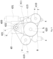
- Reference numbers are as below: 1 - base; 10 - injection table; 11 - pillar; x - linear guide rail; 2 - feeding barrel; 20 - barrel body; 21 - nozzle; 2a - plastic raw material inlet; 3 - screw rod; 4 - power system; 40 - power motor (servo motor); 400 - output shaft; 41 - injection unit; 410 - injection power component; e - injection transmission shaft; f - injection belt wheel; g - transmission lead screw; h - fixed plate; 411 - injection transmission component; i - injection transmission wheel; j - injection transmission belt; 412 - first clutch (jaw clutch); 413 - encoder; 414 - pressure sensor; 42 - feeding unit; 420 - feeding power component; a - feeding transmission shaft; b - feeding belt wheel; 421 - feeding transmission component; c - feeding transmission wheel; d - feeding transmission belt; 422 - second clutch (one-way clutch); 43 - oil pressure auxiliary
- an oil-electricity hybrid injection molding machine with three plates in this embodiment comprises a base 1, a feeding barrel 2, a screw rod 3, and a power system 4.
- the base 1 comprises an injection table 10 and pillars 11 located on the injection table 10, wherein the injection table 10 is square, with four pillars 11 correspondingly distributed at the four corners of the injection table 10, and the power system 4 is arranged on the pillars 11 through two injection pull rods 5 extending along the length direction of the screw rod 3.
- each of the two injection pull rods 5 passes through two pillars 11 located on the same side.
- the feeding barrel 2 comprises a barrel body 20 with a feeding cavity formed internally and a nozzle 21 arranged at the front end portion of the barrel body 20, wherein the barrel body 20 is provided with a plastic raw material inlet 2a.
- the screw rod 3 extends along the length direction of the feeding barrel 2 and is arranged with a rear end portion exposed out of the barrel body 20.
- the power system 4 is mainly used to drive the screw rod 3 to rotate around its axis and/or move rectilinearly along its length direction.
- an injection head plate 6, an injection second plate 7, and an injection tail plate 8 are sequentially arranged on the injection pull rods 5 from front to rear, wherein the barrel body 20 is fixed to the injection head plate 6 at the rear end portion, the injection head plate 6 and the injection tail plate 8 are fixed on the injection pull rods 5, and the injection second plate 7 is located between the injection head plate 6 and the injection tail plate 8, and is slidably arranged on the injection pull rods 5.
- the power system 4 comprises a power motor 40 with an output shaft 400 parallel to the screw rod 3, an injection unit 41, a feeding unit 42, and an oil pressure auxiliary unit 43.
- the power motor 40, the injection unit 41 and the feeding unit 42 are arranged on the injection second plate 7, and the oil pressure auxiliary unit 43 is arranged between the injection second plate 7 and the injection tail plate 8.
- the power motor is a common servo motor, and is fixed on the injection second plate 7 through a frame base, wherein the output shaft 400 is located between the injection head plate 6 and the injection second plate 7, and at the top of the injection second plate 7.
- the injection unit 41 comprises an injection power component 410 capable of pushing the screw rod 3 to move along its length direction, an injection transmission component 411 connecting the injection power component 410 to the output shaft 400 in a transmission manner, and the first clutch 412 arranged on the output shaft 400 and capable of disengaging and engaging the output shaft 400 and the injection transmission component 411.
- the feeding unit 42 comprises a feeding power component 420 connected to the output shaft 400 in a transmission manner and capable of driving the screw rod 3 to rotate, a feeding transmission component 421 connecting the feeding power component 420 to the output shaft 400 in a transmission manner, and the second clutch 422 arranged on the output shaft 400 and capable of disengaging and engaging the output shaft 400 and the feeding transmission component 421.
- the oil pressure auxiliary unit 43 comprises an auxiliary oil cylinder 430 arranged parallel to the screw rod 3, wherein the auxiliary oil cylinder 430 is arranged between the injection second plate 7 and the injection tail plate 8.
- the injection power component 410 and the feeding power component 420 share a power motor 40, and the first clutch 412 and the second clutch 422 are arranged on the output shaft 400 at interval.
- the feeding power component 420 comprises a feeding transmission shaft a coaxial with the screw rod 3 and fixedly connected to the rear end portion of the screw rod 3, and a feeding belt wheel b fixed on the feeding transmission shaft a
- the feeding transmission component 421 comprises a feeding transmission wheel c connected to the output shaft 400 through the second clutch 422, and a feeding transmission belt d connecting the feeding belt wheel b to the feeding transmission wheel c in a transmission manner.
- the injection power component 410 comprises an injection transmission shaft e coaxial with and rotatably connected to the feeding transmission shaft a, an injection belt wheel f fixed on the injection transmission shaft e, and a transmission lead screw g fixedly connected to the injection transmission shaft e, wherein the injection transmission shaft e passes through the injection second plate 7 and is rotatably arranged relative to the injection second plate 7, and the transmission lead screw g is connected to the injection tail plate 8 via a fixed plate h.
- the injection transmission component 411 comprises an injection transmission wheel i connected to the output shaft 400 through the first clutch 412, and an injection transmission belt j connecting the injection transmission wheel i to the injection belt wheel f in a transmission manner.
- the coaxial connection between the feeding transmission shaft a, the injection transmission shaft e, and the screw rod 3 realizes the relative rotation of the feeding belt wheel b and the injection belt wheel f.
- the injection unit 41 further comprises an encoder 413 located inside the injection transmission belt j and capable of synchronously moving with the injection belt wheel f, and a pressure sensor 414 arranged between the fixed plate h and the injection tail plate 8.
- the injection belt wheel f, the injection transmission wheel i, and the encoder 413 are toothed wheels
- the injection transmission belt j is a tooth-and-slot belt, wherein the encoder 413 is engaged with the injection belt wheel f.
- the movement status of the screw rod 3 can be accurately controlled to facilitate the control of injection accuracy.
- the pressure sensor 41 is mainly to obtain feedback on the pressure of the screw rod 3 during injection molding and adjust the injection process accordingly based on the feedback value.
- the feeding process is divided into:
- the oil pressure auxiliary unit 43 further comprises an energy accumulator 431 connected to the oil circuit of the auxiliary oil cylinder 430, wherein during injection, the energy accumulator 431 releases energy, and a rodless cavity of the auxiliary oil cylinder 430 is filled with oil. Under the instantaneous power provided by the energy accumulator, the synchronous movement of dual auxiliary oil cylinders ensures the speed of the injection.
- a first rod sleeve t1 is formed at one end portion thereof
- a second rod sleeve t2 is formed on the injection pull rod 5 between two pillars 11 on the same side
- an adjuster t3 is provided to drive the injection pull rod 5 to move along its length direction.
- the adjuster t3 is a telescopic rod connected to the other end portion of the injection pull rod 5 and extending in the same direction as the injection pull rod 5.
- the telescopic rod is an injection base oil cylinder t30, and under drive of the injection base oil cylinder t30, and by the setting positions of the first rod sleeve t1 and second rod sleeve t2, the adjustment of the injection position is achieved until two sides of the injection tail plate 8 fit between the tail pillar 11 and the first rod sleeve t1, and the two sides of the second rod sleeve t2 fit between the head pillar 11 and the injection head plate 6.
- first clutch 412 is a jaw clutch
- second clutch 422 is a one-way clutch, and both can be directly purchased in the market, specifically:
- the injection molding process of the injection molding machine in this embodiment is as follows: Injection: the servo motor and the energy accumulator work together, the jaw clutch is in an engaged state, the one-way clutch is disengaged, at this moment, the injection belt wheel drives the ball screw to rotate clockwise, pushing the injection second plate and the screw rod forward, at this moment, the feeding belt suffers backstop of a one-way bearing and is held stationary (keeping the screw rod from rotating).
- Holding pressure the servo motor and the energy accumulator work together to maintain a certain pressure.
- Feeding (divided into the following processes): (1), the servo motor rotates counterclockwise, at this moment, the jaw clutch is in the disengaged state, and the one-way clutch backstops to work, the feeding belt wheel drives the screw rod to rotate in place for feeding, and as the feeding action continues, the material at the front end of the screw rod accumulates more and more, generating increasing pressure, and the pressure sensed by the pressure sensor also increases; (2), when the pressure sensed by the pressure sensor is greater than a setting value, the rodless cavity of the auxiliary oil cylinder unloads oil through the proportional throttle valve, reducing the backward pressure of the screw rod, at this moment, the auxiliary oil cylinder retracts, the ball screw is driven to rotate counterclockwise, causing the screw rod to retract. When the pressure sensed by the pressure sensor is less than the setting value, the unloading amount of the proportional throttle valve is reduced, and Feeding (1) and Feeding (2) are repeated until the screw rod reaches the next initial injection position, completing the feeding action.
- the oil-electricity hybrid injection molding machine with two plates of this embodiment is the same in the basic structure and implementation principle, and differs in that there are only an injection head plate 6 and an injection tail plate 8, and in the implementation method of the power system 4.
- the barrel body 20 is fixedly connected to the injection head plate 6 at the rear end portion, the injection tail plate 8 is slidably arranged on the base 1 in a manner that moves in its length direction along with the screw rod 6, the power motor 40 and the feeding unit 42 are arranged on the injection tail plate 8, and the injection unit 41 and the auxiliary oil cylinder 430 are arranged between the injection head plate 6 and the injection tail plate 8.
- the installation of the power system has a compact structure, small volume, and easy implementation, and meanwhile, with the assistance of the auxiliary oil cylinder, it is convenient for the implementation of injection and processing, especially during injection, it can accelerate the injection speed of the screw rod at the moment the energy accumulator releases energy.
- the feeding power component 420 comprises a feeding transmission shaft a coaxial with the screw rod 3 and fixedly connected to the rear end portion of the screw rod 3, and a feeding belt wheel b fixed on the feeding transmission shaft a
- the feeding transmission component 421 comprises a feeding transmission wheel c connected to the output shaft 400 through the second clutch 422, and a feeding transmission belt d connecting the feeding belt wheel b to the feeding transmission wheel c in a transmission manner.
- the injection power component 410 comprises two sets of transmission lead screws g with centerlines parallel to the centerline of the screw rod 3 and located on two opposite sides of the screw rod 3, and injection belt wheels f with one being arranged at the screw end portion of each set of transmission lead screws g passing through the injection tail plate 8, and the injection transmission component 411 comprises an injection transmission wheel i connected to the output shaft 400 through the first clutch 412, and an injection transmission belt j connecting the injection transmission wheel i to the two injection belt wheels f in a transmission manner.
- the injection and feeding actions can be carried out under the operation of one power motor by coaxial the injection transmission wheel and the feeding transmission wheel.
- injection transmission shafts e are fixedly connected to the end portions of the transmission lead screws g, and the injection belt wheels f are fixed on the injection transmission shafts e.
- the two injection belt wheels f and the injection transmission wheel i are triangularly distributed, with the injection transmission wheel i located on the inner side of the feeding transmission belt c and the two injection belt wheels f located between the feeding belt wheel b and the injection tail plate 8.
- the injection unit 41 further comprises an encoder 413 located inside the injection transmission belt j and synchronously moving with the injection belt wheels f, and a pressure sensor 414 fixedly arranged on the injection tail plate 8 and for the feeding transmission shaft a to pass through.
- the injection belt wheels f, the injection transmission wheel i, and the encoder 413 are toothed wheels
- the injection transmission belt j is a tooth-and-slot belt, wherein the encoder 413 is engaged with the injection belt wheels f.
- auxiliary oil cylinders 430 aligned with the transmission lead screws g in an up-down direction, wherein the auxiliary oil cylinders 430 and the energy accumulator 431 are fixed on the injection head plate 6, and the transmission lead screws are common ball screw structures.
- linear guide rails x are arranged below the transmission lead screws g, the injection head plate 6 and the injection tail plate 8 are slidably arranged on the linear guide rails x at bottom, and the same injection base oil cylinder t30 as mentioned above are correspondingly arranged above each linear guide rail x, and the position adjustment is achieved under the driving of the injection base oil cylinders t30.
- the injection molding process of this embodiment is as follows: Injection: the servo motor and the energy accumulator work together, the jaw clutch is in an engaged state, the one-way clutch is disengaged, at this moment, the injection belt wheel drives the ball screws to rotate clockwise, pushing the injection tail plate and the screw rod forward, at this moment, the feeding belt suffers backstop of a one-way bearing and is held stationary (keeping the screw rod from rotating).
- Holding pressure the servo motor and the energy accumulator work together to maintain a certain pressure.
- Feeding (1), the servo motor rotates counterclockwise, at this moment, the jaw clutch is in the disengaged state, and the one-way clutch back stops to work, driving the screw rod to rotate in place for feeding, and as the feeding action continues, the material at the front end of the screw rod accumulates more and more, generating increasing pressure, and the pressure sensed by the pressure sensor also increases; (2), when the pressure sensed by the pressure sensor is greater than a setting value, the rodless cavities of the auxiliary oil cylinders unload oil through the proportional throttle valve, reducing the backward pressure of the screw rod, at this moment, the auxiliary oil cylinder rods retract, the ball screws are driven to rotate counterclockwise, causing the screw rod to retract. When the pressure sensed by the pressure sensor is less than the setting value, the unloading amount of the proportional throttle valve is reduced, and Feeding (1) and Feeding (2) are repeated until the screw rod reaches the next initial injection position, completing the feeding action.
Landscapes
- Engineering & Computer Science (AREA)
- Manufacturing & Machinery (AREA)
- Mechanical Engineering (AREA)
- Injection Moulding Of Plastics Or The Like (AREA)
Applications Claiming Priority (2)
| Application Number | Priority Date | Filing Date | Title |
|---|---|---|---|
| CN202110263907.7A CN112848160A (zh) | 2021-03-11 | 2021-03-11 | 油电混动注塑机 |
| PCT/CN2021/133066 WO2022188463A1 (zh) | 2021-03-11 | 2021-11-25 | 油电混动注塑机 |
Publications (4)
| Publication Number | Publication Date |
|---|---|
| EP4289596A1 true EP4289596A1 (de) | 2023-12-13 |
| EP4289596A4 EP4289596A4 (de) | 2024-07-24 |
| EP4289596C0 EP4289596C0 (de) | 2025-10-22 |
| EP4289596B1 EP4289596B1 (de) | 2025-10-22 |
Family
ID=75994037
Family Applications (1)
| Application Number | Title | Priority Date | Filing Date |
|---|---|---|---|
| EP21929925.2A Active EP4289596B1 (de) | 2021-03-11 | 2021-11-25 | Öl-elektrische hybrid-spritzgiessmaschine |
Country Status (5)
| Country | Link |
|---|---|
| US (1) | US12528239B2 (de) |
| EP (1) | EP4289596B1 (de) |
| JP (1) | JP7766948B2 (de) |
| CN (1) | CN112848160A (de) |
| WO (1) | WO2022188463A1 (de) |
Families Citing this family (3)
| Publication number | Priority date | Publication date | Assignee | Title |
|---|---|---|---|---|
| CN112848160A (zh) * | 2021-03-11 | 2021-05-28 | 苏州锦珂塑胶科技有限公司 | 油电混动注塑机 |
| CN115534248B (zh) * | 2022-09-23 | 2025-12-02 | 苏州锦珂塑胶科技有限公司 | 一种注塑机 |
| CN116140148B (zh) * | 2022-12-15 | 2025-12-02 | 珠海格力智能装备有限公司 | 注射设备 |
Family Cites Families (34)
| Publication number | Priority date | Publication date | Assignee | Title |
|---|---|---|---|---|
| JPS61252125A (ja) * | 1985-04-30 | 1986-11-10 | Meiki Co Ltd | 射出成形装置 |
| JPH0722813B2 (ja) * | 1989-01-30 | 1995-03-15 | 宇部興産株式会社 | 射出装置 |
| JPH0679824B2 (ja) * | 1992-01-17 | 1994-10-12 | 日精樹脂工業株式会社 | 射出成形機 |
| JPH07156225A (ja) * | 1993-12-08 | 1995-06-20 | Japan Steel Works Ltd:The | 射出成形機の射出装置 |
| DE19532267C2 (de) * | 1995-09-01 | 1998-03-19 | Ferromatik Milacron Maschinenb | Elektrischer Antrieb mit hydraulischer Unterstützung in einer Spritzgießmaschine |
| US5645868A (en) * | 1995-11-17 | 1997-07-08 | Cincinnati Milacron Inc. | Drive apparatus for an injection unit |
| US6120277A (en) * | 1997-07-28 | 2000-09-19 | Cincinnatti Milacron Inc. | Hybrid injection molding machine |
| US5916602A (en) * | 1997-07-28 | 1999-06-29 | Cincinnati Milacron Inc. | Injection molding machine having a hydraulically operated clamping system |
| US6086353A (en) * | 1998-02-17 | 2000-07-11 | Cincinnati Milacron Inc. | Two-stage electric injection unit with rotating plunger |
| JP2000037755A (ja) * | 1998-07-21 | 2000-02-08 | Niigata Eng Co Ltd | 射出成形機の射出装置及び射出方法 |
| JP4130062B2 (ja) | 1998-09-30 | 2008-08-06 | ミラクロン・インコーポレーテッド | 混成射出成形機 |
| JP3653406B2 (ja) * | 1998-12-15 | 2005-05-25 | 東洋機械金属株式会社 | 射出成形機の射出装置 |
| US6478572B1 (en) | 2000-07-06 | 2002-11-12 | Husky Injection Molding Systems, Ltd. | Energy efficient extruder drive |
| WO2002040243A1 (de) * | 2000-11-14 | 2002-05-23 | Bosch Rexroth Ag | Antriebsvorrichtung zum verschieben zweier geradlinig bewegbarer komponenten einer kunststoffspritzgiessmaschine |
| DE10060087C5 (de) * | 2000-12-02 | 2005-11-17 | Battenfeld Gmbh | Einspritzaggregat für eine Spritzgießmaschine |
| AU2003273716A1 (en) * | 2002-12-04 | 2004-06-23 | Netstal-Maschinen Ag | Method and installation for producing plastic parts |
| US7168944B2 (en) * | 2002-12-10 | 2007-01-30 | Husky Injection Molding Systems Ltd. | Energy efficient extruder drive |
| JP2004243687A (ja) | 2003-02-14 | 2004-09-02 | Toyo Mach & Metal Co Ltd | 射出成形機 |
| DE10318958B3 (de) * | 2003-04-26 | 2004-08-05 | Krauss-Maffei Kunststofftechnik Gmbh | Hybrid-Einspritzeinheit und Spritzgießmaschine mit einer Hybrid-Einspritzeinheit |
| EP1801850B1 (de) * | 2004-09-17 | 2014-11-26 | Nikon Corporation | Substrat und haltevorrichtung, belichtungsvorrichtung und bauelemente-herstellungsverfahren |
| KR100732596B1 (ko) * | 2006-02-24 | 2007-06-27 | 허스키 인젝션 몰딩 시스템즈 리미티드 | 축을 회전하고 이동하기 위한 구동 조립체 |
| JP5587568B2 (ja) | 2009-07-14 | 2014-09-10 | 東洋機械金属株式会社 | ダイカストマシン |
| CN101695864B (zh) * | 2009-10-29 | 2012-05-30 | 泰瑞机器制造(中国)有限公司 | 注射机电液混合驱动注射机构及其注射方法 |
| JP5524348B2 (ja) | 2009-12-04 | 2014-06-18 | 歩 明 黄 | 型締装置 |
| KR20160002717U (ko) * | 2015-01-27 | 2016-08-04 | 긴 리 | 완전 전동 플라스틱 사출기 |
| CN104859087A (zh) * | 2015-04-20 | 2015-08-26 | 北京化工大学 | 一种电液复合式超高速节能注塑成型机 |
| CN104790022B (zh) * | 2015-04-27 | 2017-09-12 | 栾善东 | 一种全自动pcb垂直连续电镀装置 |
| CN106671345A (zh) * | 2016-12-09 | 2017-05-17 | 天津格林特科技有限公司 | 一种注塑设备 |
| CN207535251U (zh) * | 2017-09-29 | 2018-06-26 | 广东伟达智能装备股份有限公司 | 一种注塑机混合动力电动塑化注射装置 |
| CN208067098U (zh) * | 2018-03-31 | 2018-11-09 | 重庆科聚机械铸造有限公司 | 一种安全型安装支架 |
| CN209992287U (zh) * | 2018-11-15 | 2020-01-24 | 伍素实业发展(上海)有限公司 | 检测注塑件产品性能装置 |
| CN112388922A (zh) * | 2020-10-27 | 2021-02-23 | 苏州锦珂塑胶科技有限公司 | 一种射出和加料相互协作的注塑机 |
| CN112848160A (zh) | 2021-03-11 | 2021-05-28 | 苏州锦珂塑胶科技有限公司 | 油电混动注塑机 |
| CN214773801U (zh) * | 2021-03-11 | 2021-11-19 | 苏州锦珂塑胶科技有限公司 | 油电混动注塑机 |
-
2021
- 2021-03-11 CN CN202110263907.7A patent/CN112848160A/zh active Pending
- 2021-11-25 JP JP2023553649A patent/JP7766948B2/ja active Active
- 2021-11-25 EP EP21929925.2A patent/EP4289596B1/de active Active
- 2021-11-25 WO PCT/CN2021/133066 patent/WO2022188463A1/zh not_active Ceased
- 2021-11-25 US US18/550,010 patent/US12528239B2/en active Active
Also Published As
| Publication number | Publication date |
|---|---|
| WO2022188463A1 (zh) | 2022-09-15 |
| EP4289596C0 (de) | 2025-10-22 |
| JP7766948B2 (ja) | 2025-11-11 |
| CN112848160A (zh) | 2021-05-28 |
| EP4289596B1 (de) | 2025-10-22 |
| JP2024509203A (ja) | 2024-02-29 |
| US20240157615A1 (en) | 2024-05-16 |
| US12528239B2 (en) | 2026-01-20 |
| EP4289596A4 (de) | 2024-07-24 |
Similar Documents
| Publication | Publication Date | Title |
|---|---|---|
| US12528239B2 (en) | Oil-electricity hybrid injection molding machine | |
| EP0090863B1 (de) | Spritzgussvorrichtung | |
| JPS6157168B2 (de) | ||
| US20080166446A1 (en) | Motor-driven injection molding machine and molding method using the same | |
| JPS60174623A (ja) | 射出成形機 | |
| CN104859087A (zh) | 一种电液复合式超高速节能注塑成型机 | |
| JP6457750B2 (ja) | 成形装置 | |
| KR100467984B1 (ko) | 사출성형기 및 사출성형기에 있어서의 스크루위치 제어방법 | |
| JPH1134127A (ja) | 射出成形機の射出装置 | |
| CN110385841A (zh) | 用于液压缸注塑机的低惯量射出机构 | |
| CN108943625B (zh) | 高性能电动注塑装置 | |
| CN108099139A (zh) | 一种注塑机混合动力电动塑化注射装置 | |
| CN214773801U (zh) | 油电混动注塑机 | |
| CN102582043B (zh) | 一种全电动超高速注塑成型机 | |
| CN204525928U (zh) | 一种电液复合式超高速节能注塑成型机 | |
| JPS631516A (ja) | 射出成形機 | |
| JPH0839631A (ja) | 電動射出成形機の射出装置 | |
| WO2016050002A1 (zh) | 电动液压混合式射出机构 | |
| JP2001341176A (ja) | 電動駆動式射出装置 | |
| EP1219403B1 (de) | Verbesserte Spritzgiessanordnung für Spritzgiesspressen für Kunststoffe | |
| JPH01238917A (ja) | 射出成形機の射出方法および装置 | |
| CN220373839U (zh) | 一种新型电动熔胶射台装置 | |
| CN201745140U (zh) | 全电动注塑机差动式合模机构 | |
| JP2978639B2 (ja) | サーボモータ駆動の射出成形機 | |
| CN108927965A (zh) | 一种高性能电动注塑机构 |
Legal Events
| Date | Code | Title | Description |
|---|---|---|---|
| STAA | Information on the status of an ep patent application or granted ep patent |
Free format text: STATUS: THE INTERNATIONAL PUBLICATION HAS BEEN MADE |
|
| PUAI | Public reference made under article 153(3) epc to a published international application that has entered the european phase |
Free format text: ORIGINAL CODE: 0009012 |
|
| STAA | Information on the status of an ep patent application or granted ep patent |
Free format text: STATUS: REQUEST FOR EXAMINATION WAS MADE |
|
| 17P | Request for examination filed |
Effective date: 20230908 |
|
| AK | Designated contracting states |
Kind code of ref document: A1 Designated state(s): AL AT BE BG CH CY CZ DE DK EE ES FI FR GB GR HR HU IE IS IT LI LT LU LV MC MK MT NL NO PL PT RO RS SE SI SK SM TR |
|
| DAV | Request for validation of the european patent (deleted) | ||
| DAX | Request for extension of the european patent (deleted) | ||
| A4 | Supplementary search report drawn up and despatched |
Effective date: 20240621 |
|
| RIC1 | Information provided on ipc code assigned before grant |
Ipc: B29C 45/82 20060101ALI20240617BHEP Ipc: B29C 45/17 20060101ALI20240617BHEP Ipc: B29C 45/76 20060101ALI20240617BHEP Ipc: B29C 45/50 20060101AFI20240617BHEP |
|
| GRAP | Despatch of communication of intention to grant a patent |
Free format text: ORIGINAL CODE: EPIDOSNIGR1 |
|
| STAA | Information on the status of an ep patent application or granted ep patent |
Free format text: STATUS: GRANT OF PATENT IS INTENDED |
|
| INTG | Intention to grant announced |
Effective date: 20250612 |
|
| GRAS | Grant fee paid |
Free format text: ORIGINAL CODE: EPIDOSNIGR3 |
|
| GRAA | (expected) grant |
Free format text: ORIGINAL CODE: 0009210 |
|
| STAA | Information on the status of an ep patent application or granted ep patent |
Free format text: STATUS: THE PATENT HAS BEEN GRANTED |
|
| AK | Designated contracting states |
Kind code of ref document: B1 Designated state(s): AL AT BE BG CH CY CZ DE DK EE ES FI FR GB GR HR HU IE IS IT LI LT LU LV MC MK MT NL NO PL PT RO RS SE SI SK SM TR |
|
| REG | Reference to a national code |
Ref country code: CH Ref legal event code: F10 Free format text: ST27 STATUS EVENT CODE: U-0-0-F10-F00 (AS PROVIDED BY THE NATIONAL OFFICE) Effective date: 20251022 Ref country code: GB Ref legal event code: FG4D |
|
| REG | Reference to a national code |
Ref country code: DE Ref legal event code: R096 Ref document number: 602021041071 Country of ref document: DE |
|
| REG | Reference to a national code |
Ref country code: IE Ref legal event code: FG4D |
|
| U01 | Request for unitary effect filed |
Effective date: 20251104 |
|
| U07 | Unitary effect registered |
Designated state(s): AT BE BG DE DK EE FI FR IT LT LU LV MT NL PT RO SE SI Effective date: 20251110 |
|
| U20 | Renewal fee for the european patent with unitary effect paid |
Year of fee payment: 5 Effective date: 20251230 |