EP4289502A1 - Synthesis apparatus, synthesizer and synthesis method - Google Patents
Synthesis apparatus, synthesizer and synthesis method Download PDFInfo
- Publication number
- EP4289502A1 EP4289502A1 EP21923848.2A EP21923848A EP4289502A1 EP 4289502 A1 EP4289502 A1 EP 4289502A1 EP 21923848 A EP21923848 A EP 21923848A EP 4289502 A1 EP4289502 A1 EP 4289502A1
- Authority
- EP
- European Patent Office
- Prior art keywords
- biochips
- sorting
- synthesis
- assembly
- control device
- Prior art date
- Legal status (The legal status is an assumption and is not a legal conclusion. Google has not performed a legal analysis and makes no representation as to the accuracy of the status listed.)
- Pending
Links
Images






Classifications
-
- B—PERFORMING OPERATIONS; TRANSPORTING
- B01—PHYSICAL OR CHEMICAL PROCESSES OR APPARATUS IN GENERAL
- B01J—CHEMICAL OR PHYSICAL PROCESSES, e.g. CATALYSIS OR COLLOID CHEMISTRY; THEIR RELEVANT APPARATUS
- B01J19/00—Chemical, physical or physico-chemical processes in general; Their relevant apparatus
- B01J19/0046—Sequential or parallel reactions, e.g. for the synthesis of polypeptides or polynucleotides; Apparatus and devices for combinatorial chemistry or for making molecular arrays
-
- B—PERFORMING OPERATIONS; TRANSPORTING
- B01—PHYSICAL OR CHEMICAL PROCESSES OR APPARATUS IN GENERAL
- B01J—CHEMICAL OR PHYSICAL PROCESSES, e.g. CATALYSIS OR COLLOID CHEMISTRY; THEIR RELEVANT APPARATUS
- B01J19/00—Chemical, physical or physico-chemical processes in general; Their relevant apparatus
-
- B—PERFORMING OPERATIONS; TRANSPORTING
- B01—PHYSICAL OR CHEMICAL PROCESSES OR APPARATUS IN GENERAL
- B01L—CHEMICAL OR PHYSICAL LABORATORY APPARATUS FOR GENERAL USE
- B01L3/00—Containers or dishes for laboratory use, e.g. laboratory glassware; Droppers
- B01L3/50—Containers for the purpose of retaining a material to be analysed, e.g. test tubes
- B01L3/502—Containers for the purpose of retaining a material to be analysed, e.g. test tubes with fluid transport, e.g. in multi-compartment structures
- B01L3/5027—Containers for the purpose of retaining a material to be analysed, e.g. test tubes with fluid transport, e.g. in multi-compartment structures by integrated microfluidic structures, i.e. dimensions of channels and chambers are such that surface tension forces are important, e.g. lab-on-a-chip
- B01L3/502715—Containers for the purpose of retaining a material to be analysed, e.g. test tubes with fluid transport, e.g. in multi-compartment structures by integrated microfluidic structures, i.e. dimensions of channels and chambers are such that surface tension forces are important, e.g. lab-on-a-chip characterised by interfacing components, e.g. fluidic, electrical, optical or mechanical interfaces
-
- C—CHEMISTRY; METALLURGY
- C07—ORGANIC CHEMISTRY
- C07H—SUGARS; DERIVATIVES THEREOF; NUCLEOSIDES; NUCLEOTIDES; NUCLEIC ACIDS
- C07H1/00—Processes for the preparation of sugar derivatives
-
- C—CHEMISTRY; METALLURGY
- C07—ORGANIC CHEMISTRY
- C07H—SUGARS; DERIVATIVES THEREOF; NUCLEOSIDES; NUCLEOTIDES; NUCLEIC ACIDS
- C07H21/00—Compounds containing two or more mononucleotide units having separate phosphate or polyphosphate groups linked by saccharide radicals of nucleoside groups, e.g. nucleic acids
- C07H21/04—Compounds containing two or more mononucleotide units having separate phosphate or polyphosphate groups linked by saccharide radicals of nucleoside groups, e.g. nucleic acids with deoxyribosyl as saccharide radical
-
- G—PHYSICS
- G01—MEASURING; TESTING
- G01N—INVESTIGATING OR ANALYSING MATERIALS BY DETERMINING THEIR CHEMICAL OR PHYSICAL PROPERTIES
- G01N35/00—Automatic analysis not limited to methods or materials provided for in any single one of groups G01N1/00 - G01N33/00; Handling materials therefor
- G01N35/00584—Control arrangements for automatic analysers
- G01N35/00722—Communications; Identification
- G01N35/00732—Identification of carriers, materials or components in automatic analysers
-
- G—PHYSICS
- G01—MEASURING; TESTING
- G01N—INVESTIGATING OR ANALYSING MATERIALS BY DETERMINING THEIR CHEMICAL OR PHYSICAL PROPERTIES
- G01N35/00—Automatic analysis not limited to methods or materials provided for in any single one of groups G01N1/00 - G01N33/00; Handling materials therefor
- G01N35/02—Automatic analysis not limited to methods or materials provided for in any single one of groups G01N1/00 - G01N33/00; Handling materials therefor using a plurality of sample containers moved by a conveyor system past one or more treatment or analysis stations
-
- G—PHYSICS
- G01—MEASURING; TESTING
- G01N—INVESTIGATING OR ANALYSING MATERIALS BY DETERMINING THEIR CHEMICAL OR PHYSICAL PROPERTIES
- G01N35/00—Automatic analysis not limited to methods or materials provided for in any single one of groups G01N1/00 - G01N33/00; Handling materials therefor
- G01N35/02—Automatic analysis not limited to methods or materials provided for in any single one of groups G01N1/00 - G01N33/00; Handling materials therefor using a plurality of sample containers moved by a conveyor system past one or more treatment or analysis stations
- G01N35/04—Details of the conveyor system
-
- B—PERFORMING OPERATIONS; TRANSPORTING
- B01—PHYSICAL OR CHEMICAL PROCESSES OR APPARATUS IN GENERAL
- B01J—CHEMICAL OR PHYSICAL PROCESSES, e.g. CATALYSIS OR COLLOID CHEMISTRY; THEIR RELEVANT APPARATUS
- B01J2219/00—Chemical, physical or physico-chemical processes in general; Their relevant apparatus
- B01J2219/00274—Sequential or parallel reactions; Apparatus and devices for combinatorial chemistry or for making arrays; Chemical library technology
- B01J2219/00277—Apparatus
- B01J2219/0054—Means for coding or tagging the apparatus or the reagents
-
- B—PERFORMING OPERATIONS; TRANSPORTING
- B01—PHYSICAL OR CHEMICAL PROCESSES OR APPARATUS IN GENERAL
- B01J—CHEMICAL OR PHYSICAL PROCESSES, e.g. CATALYSIS OR COLLOID CHEMISTRY; THEIR RELEVANT APPARATUS
- B01J2219/00—Chemical, physical or physico-chemical processes in general; Their relevant apparatus
- B01J2219/00274—Sequential or parallel reactions; Apparatus and devices for combinatorial chemistry or for making arrays; Chemical library technology
- B01J2219/00583—Features relative to the processes being carried out
- B01J2219/00603—Making arrays on substantially continuous surfaces
- B01J2219/00605—Making arrays on substantially continuous surfaces the compounds being directly bound or immobilised to solid supports
- B01J2219/00608—DNA chips
-
- B—PERFORMING OPERATIONS; TRANSPORTING
- B01—PHYSICAL OR CHEMICAL PROCESSES OR APPARATUS IN GENERAL
- B01J—CHEMICAL OR PHYSICAL PROCESSES, e.g. CATALYSIS OR COLLOID CHEMISTRY; THEIR RELEVANT APPARATUS
- B01J2219/00—Chemical, physical or physico-chemical processes in general; Their relevant apparatus
- B01J2219/00274—Sequential or parallel reactions; Apparatus and devices for combinatorial chemistry or for making arrays; Chemical library technology
- B01J2219/0068—Means for controlling the apparatus of the process
- B01J2219/00686—Automatic
-
- B—PERFORMING OPERATIONS; TRANSPORTING
- B01—PHYSICAL OR CHEMICAL PROCESSES OR APPARATUS IN GENERAL
- B01J—CHEMICAL OR PHYSICAL PROCESSES, e.g. CATALYSIS OR COLLOID CHEMISTRY; THEIR RELEVANT APPARATUS
- B01J2219/00—Chemical, physical or physico-chemical processes in general; Their relevant apparatus
- B01J2219/00274—Sequential or parallel reactions; Apparatus and devices for combinatorial chemistry or for making arrays; Chemical library technology
- B01J2219/00718—Type of compounds synthesised
- B01J2219/0072—Organic compounds
- B01J2219/00722—Nucleotides
-
- B—PERFORMING OPERATIONS; TRANSPORTING
- B01—PHYSICAL OR CHEMICAL PROCESSES OR APPARATUS IN GENERAL
- B01L—CHEMICAL OR PHYSICAL LABORATORY APPARATUS FOR GENERAL USE
- B01L2200/00—Solutions for specific problems relating to chemical or physical laboratory apparatus
- B01L2200/16—Reagents, handling or storing thereof
-
- B—PERFORMING OPERATIONS; TRANSPORTING
- B01—PHYSICAL OR CHEMICAL PROCESSES OR APPARATUS IN GENERAL
- B01L—CHEMICAL OR PHYSICAL LABORATORY APPARATUS FOR GENERAL USE
- B01L2300/00—Additional constructional details
- B01L2300/06—Auxiliary integrated devices, integrated components
- B01L2300/0627—Sensor or part of a sensor is integrated
- B01L2300/0636—Integrated biosensor, microarrays
-
- G—PHYSICS
- G01—MEASURING; TESTING
- G01N—INVESTIGATING OR ANALYSING MATERIALS BY DETERMINING THEIR CHEMICAL OR PHYSICAL PROPERTIES
- G01N35/00—Automatic analysis not limited to methods or materials provided for in any single one of groups G01N1/00 - G01N33/00; Handling materials therefor
- G01N35/00029—Automatic analysis not limited to methods or materials provided for in any single one of groups G01N1/00 - G01N33/00; Handling materials therefor provided with flat sample substrates, e.g. slides
- G01N2035/00099—Characterised by type of test elements
- G01N2035/00158—Elements containing microarrays, i.e. "biochip"
-
- G—PHYSICS
- G01—MEASURING; TESTING
- G01N—INVESTIGATING OR ANALYSING MATERIALS BY DETERMINING THEIR CHEMICAL OR PHYSICAL PROPERTIES
- G01N35/00—Automatic analysis not limited to methods or materials provided for in any single one of groups G01N1/00 - G01N33/00; Handling materials therefor
- G01N35/02—Automatic analysis not limited to methods or materials provided for in any single one of groups G01N1/00 - G01N33/00; Handling materials therefor using a plurality of sample containers moved by a conveyor system past one or more treatment or analysis stations
- G01N35/04—Details of the conveyor system
- G01N2035/0474—Details of actuating means for conveyors or pipettes
- G01N2035/0475—Details of actuating means for conveyors or pipettes electric, e.g. stepper motor, solenoid
Definitions
- the subject matter relates to synthesis of biomacromolecules, and more particularly, to a synthesis apparatus, a synthesizer, and a synthesis method of biomacromolecules.
- biomacromolecules include proteins, nucleic acids (DNA, RNA, etc.), and carbohydrates. Most biomacromolecules are polymerized from simple constituent structures. The constituent unit of protein is amino acid, and the constituent unit of nucleic acid is nucleotide. The biomacromolecules can be synthesized from simple structures within organisms. If the biomacromolecules need to be synthesized artificially, a special instrument such as a synthesizer, is needed.
- the existing synthesizer includes fixing an oligonucleotide single strand on a glass synthesis column, immersing the synthesis column in a container, and then adding various corresponding nucleotide reagents to the container, so that the single-stranded oligonucleotides can be continuously extended according to a required sequence.
- the principle and process of such synthesizer is complex, the synthesis flux is low, and the consumption of reagents is large.
- the synthesis cycle is long, and the target synthesis task cannot be changed.
- the sorting device includes a plurality of first sorting assemblies located on a side of the transporting assembly and corresponding to the reaction vessels, the first sorting assemblies are configured to sort the biochips located on the transporting assembly to the reaction vessels, and each of the reaction vessels corresponding to a current synthesis reaction performed on a respective one of the biochips when controlled by the control device.
- the transfer device is configured to transfer the biochips in the reaction vessels to the feeding device.
- each of the first sorting assemblies includes a first site sensor and a first selection device corresponding to the first site sensor, the first site sensor is configured to sense whether one of the biochips has been transported to the first site sensor and send a site sensing information to the control device, the first selection device is configured to transfer the one of the biochips to a respective one of the reaction vessels when controlled by the control device.
- the first selection device includes a gas supply device on a side of the transporting assembly and a storage device on another side of the transporting assembly, the gas supply device is configured to blow the one of the biochips to the storage device when controlled by the control device, the storage device is configured to transfer the one of the biochips to a respective one of the reaction vessels.
- the transfer device further includes a negative pressure reflux device and a reflux storage device;
- the negative pressure reflux device is connected to the first recovery vessel, and is configured to transport the one of the biochips in the first recovery vessel to the reflux storage device when controlled by the control device;
- the reflux storage device is configured to place the reflux storage device to the feeding device.
- the synthesis apparatus further includes a residue sensor and a second recovery vessel, wherein the residue sensor is located at an end of the first sorting assemblies away from the recognition device, and is configured to sense whether one of the biochips has been sent to a predetermined position and transmit a residue sensing information to the control device; the second recovery vessel is placed at an end of the transporting assembly away from the feeding device, and is configured to receive one of the biochips from the transporting assembly which is not successfully sorted; the negative pressure reflux device is further configured to transport the one of biochips in the second recovery vessel to the reflux storage device when controlled by the control device.
- the synthesis apparatus further includes a waste recovery vessel, wherein the sorting device further includes a third sorting assembly, the third sorting assembly is located between the recognition device and the first sorting assemblies and corresponds to the waste recovery vessel; the third sorting assembly is configured to sort one of the biochips which is determined as a waste into the waste recovery vessel when controlled by the control device.
- the synthesis apparatus further includes a finished material recovery vessel, wherein the sorting device further includes a fourth sorting assembly, the fourth sorting assembly is located between the recognition device and the first sorting assemblies and corresponds to the finished material recovery vessel; the fourth sorting assembly is configured to sort one of the biochips which completes all synthesis reactions to the finished material recovery vessel when controlled by the control device.
- a synthesizer which includes the above-mentioned synthesis apparatus, a control device configured to control the synthesis apparatus, and an input member and an output member each connected to the control device.
- the control device is configured to execute corresponding programs to control the synthesis apparatus to operate according to a content input from the input member, and display relevant information on the output member.
- a synthesis method of biomacromolecules which includes:
- the synthesizer and the synthesis method multiple biochips placed on the transporting assembly can be simultaneously sorted by the first sorting assemblies arranged on a side of the transporting assembly, which improves the sorting efficiency of the biochips and shortening the synthesis cycle.
- the biochip since the reaction vessels correspond to the first sorting assemblies, the biochip may be sorted to the corresponding reaction vessel according to the identification information of the biochip.
- the modified or newly added synthesis sequence may be adapted by changing the sorting order, so as to achieve a higher degree of freedom of synthesis.
- oligonucleotide single strand 10 oligonucleotide single strand 10; biochip 20; identification 21; synthesizer 30; housing 31; display 32; input member 33; control device 34; synthesis apparatus 35; channel 36; feeding device 351; recognition device 352; reaction device 353; sorting device 354; transfer device 355; transporting assembly 3511; guide rail 3512; conveying belt 3513; first step motor 3514; bottom plate 35121; cover plate 35122; limit plate 35123; feeding groove 35151; vibrating disc 3515; guide member 3516; vibrating rail 35152; image capturing member 3521; reaction vessel 3531; synthesis reaction column 35311; sealing cover 35312; opening and closing driver 3532; positioning body 3533; container driver 3534; first sorting assembly 3541; site sensor 35411; selection device 35412; gas supply device 35413; storage device 35414; nozzle 35415; switch 35416; storage bin 35417; lifting member 35418; lifting driver 35419; second step motor 3
- ком ⁇ онент when a component is referred to as being or “mounted on” another component, the component can be directly on another component or a middle component may exist therebetween. When a component is considered to be “arranged on” another component, the component can be directly on another component or a middle component may exist therebetween.
- a synthesizer provided by the present disclosure may be used to synthesize biomacromolecules, including but not limited to proteins, nucleic acids (DNA, RNA, etc.), carbohydrates, etc.
- a carrier for the synthesis of the biomacromolecules is a biochip.
- the biomacromolecules are fixed on a surface of the biochip, and are continuously extended in the synthesizer according to a required sequence to obtain a required macromolecule structure.
- oligonucleotide single strands 10 are fixed on the surface of the biochip 20.
- a number of oligonucleotide single strands may be fixed on the surface of biochip 20 (two oligonucleotide single strands are shown in the figure).
- Each oligonucleotide single strand is continuously extended by the synthesizer of the present disclosure according to the required sequence.
- a small segment of short strand of the oligonucleotide single strand may be pre-fixed on the surface of the biochip 20.
- a specific biochemical adaptor may be arranged on the surface of the biochip 20, and the required biomacromolecule structure may be obtained by continuously extending the pre-fixed short strand of the oligonucleotide single strand or the specific biochemical adaptor.
- An identification 21 is provided on the biochip 20, which is shown in the shaded portion of the figure.
- the identification 21 is the identity of the corresponding biochip 20, which is used to distinguish the biochip 20 from other biochips 20.
- the identification 21 may be represented by a two-dimensional code, a barcode, an RFID tag, or other existing methods. In other embodiments, the identification 21 may also be arranged on another specific location or several other specific locations of the biochip 20.
- the synthesizer 30 is used to synthesize the biomacromolecules.
- the synthesizer 30 includes a housing 31, and a display 32 and an input member 33 both fixed on the housing .
- the display 32 and the input member 33 are integrated as a touch screen display. It may be understood that the input member 33 may also be set separately from the display 32, which includes a keyboard, a mouse, or another input device.
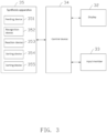
- the synthesizer 30 further includes a control device 34 and a synthesis apparatus 35 located in the housing 31.
- the control device 34 is communicated with each of the display 32, the input component 33, and the synthesis apparatus 35, and may be as large as a server, a host, or as small as a chip.
- the control device 34 is used to execute corresponding programs according to a content input by the input member 33, thereby controlling the synthesis apparatus 35 and display relevant information (such as abnormal information, completion information, etc.) on the display 32.
- the control device 34 may be arranged inside the housing 31 or outside the housing 31, and may be a local control device or a remote control device.
- the content input by the input member 33 may be used to set a synthesis reaction required for each biochip 20 or to define abnormal characteristics of an abnormal biochip 20 (for example, the identification is unrecognizable, etc.).
- At least one channel 36 connecting the inside of the synthesizer 30 is defined on the housing 31.
- the internal structure of the synthesizer 30 may be touched through the channel 36, and the biochip 20 used for the synthesis of the oligonucleotide primer may also be placed into the synthesizer 30 through the channel 36.
- the synthesis apparatus 35 includes a feeding device 351 for transporting the biochips, a recognition device 352 for recognizing the biochips, a reaction device 353 for performing the synthesis reaction on the biochips, a sorting device 354 for sorting the biochips, and a transfer device 355 for transferring the biochips.
- the feeding device 351 includes a transporting assembly 3511 for simultaneously transporting a number of biochips.
- the transporting assembly 3511 includes a guide rail 3512, a conveying belt 3513, and a first step motor 3514.
- the conveying belt 3513 is wound on the guide rail 3512 along an extended direction of the guide rail 3512, and further sleeved on an output shaft of the first step motor 3514.
- the conveying belt 3513 is used to move along the guide rail 3512 when driven by the first step motor 3514, thereby transporting the biochips on the conveying belt 3513.
- the guide rail 3512 includes a bottom plate 35121, a transparent cover plate 35122, and two limit plates 35123 connected between the bottom plate 35121 and the cover plate 35122 and opposite to each other.
- the first step motor 3514 is located at an end of the bottom plate 35121 away from the transporting assembly 3511.
- the conveying belt 3513 is located between the two limit plates 35123, one portion of the conveying belt 3513 is located between the bottom plate 35121 and the cover plate 35122, and the remaining portion is located outside the guide rail 3512.
- the feeding device 351 further includes a vibrating disc 3515 with a feeding groove 35151 and a discharge port (not shown in the figure), and further includes a hollow guide member 3516.
- the guide member 3516 is communicated with the discharge port of the vibrating disc 3515.
- a vibrating rail 35152 is arranged in the vibrating disc 3515.
- the vibrating rail 35152 is in a circular and progressive shape, which is used to orderly arrange the biochips that enter the feeding groove 35151 and output the biochips to the guide member 3516.
- An end of the guide member 3516 away from the vibration disk 3515 is located above the transporting assembly 3511, which allows each biochip that is output to the guide member 3516 to slide onto the transporting assembly 3511 under its own gravity.
- the recognition device 352 includes an image capturing member 3521 and an image recognition member (not shown).
- the image capturing member 3521 is located above the transporting assembly 3511, and is used to capture the image of each biochips transported by the transporting assembly 3511.
- the image recognition member is used to identify the identification of the biochip according to the image of the biochip, and send the generated identification information to the control device 34. It may be understood that the image recognition member may also be set in the control device 34.
- the image capturing member 3521 transmits the captured image of the biochip to the control device 34.
- the control device 34 recognizes the identification of the biochip according to the image of the biochip, thereby obtaining the identification information.
- the reaction device 353 is located on a side of the recognition device 352 away from the feeding device 351, and includes a number of reaction vessels 3531.
- Each reaction vessel 3531 is used for the synthesis reaction or the cleaning of the biochip located in the reaction vessel 3531.
- Each reaction vessel 3531 is for completing a different synthesis reaction.
- the number of reaction vessels 3531 is four.
- the four reaction vessels 3531 are respectively used for the synthesis of adenine (A), thymine (T), cytosine (C), and guanine (G).
- each reaction vessel 3531 includes a synthesis reaction column 35311 and a sealing cover 35312 that may be opened and closed with respect to the synthesis reaction column 35311.
- the sealing cover 35312 is used to seal the synthesis reaction column 35311 to complete the synthesis reaction on the biochip.
- the biochip can be placed into the synthesis reaction column 35311.
- the reaction device 353 further includes an opening and closing driver 3532.
- the opening and closing driver 3532 is connected to the sealing cover 35312, and is used to drive the sealing cover 35312 to move upwards and downwards, causing the sealing cover 35312 to leave or seal the synthesis reaction column 35311.
- the biochips are discharged when the reaction vessels 3531 rotate by the preset angle, and the reaction vessels 3531 can further receive the biochips after discharging the biochips.
- the control device 34 sends the rotation command to the container driver 3534 when the reaction devices 353 complete the synthesis reaction.
- the position of the positioning body 3533 after rotating by the preset angle along the first direction is the second position.
- the position of the positioning body 3533 after rotating along the direction opposite of the first direction is the first position.
- the sorting device 354 includes a number of first sorting assemblies 3541.
- the first sorting assemblies 3541 are located on a side of the transporting assembly 3511 and correspond to the reaction vessels 3531.
- the control device 34 determines the synthesis sequence of each biochip and the current synthesis reaction according to the identification information. When one biochip is transported to the first sorting assembly 3541 corresponding to the reaction vessel 3531 for performing the current synthesis reactions, the control device 34 controls the first sorting assembly 3541 to sort the biochip to the corresponding reaction vessel 3531.
- each first sorting assembly 3541 includes a site sensor 35411 and a selection device (not shown) corresponding to the site sensor 35411.
- the site sensor 35411 is located above the selection device, and is used to sense whether a biochip has been transported to the site sensor 35411 and send a site sensing information to the control device 34.
- the control device 34 determines the synthesis sequence of the current biochip and the current synthesis reaction according to the identification information of the current biochip, and determines according to the current synthesis reaction whether the biochip sensed by the site sensor 35411 is sorted by the selection device corresponding to the site sensor 35411.
- the biochip is subjected to a cytosine synthesis reaction instead of the adenine synthesis reaction corresponding to the adenine synthesis site sensor.
- the control device 34 will not send the sorting command to the selection device corresponding to the adenine synthesis site sensor. As such, the biochip will continue to be transported to the next site sensor (hereinafter, thymine synthesis site sensor for simplicity). Similarly, the control device 34 will not send the sorting command to the selection device corresponding to the thymine synthesis position sensor. The biochip continues to be transported to the next site sensor (hereinafter, cytosine synthesis site sensor for simplicity).
- the selection device includes a gas supply device 35413 on a side of the transporting assembly and a storage device 35414 on another side of the transporting assembly.
- the gas supply device 35413 is used to blow the corresponding biochip to the storage device 35414 according to the sorting command from the control device 34.
- the storage device 35414 is used to transfer the biochip to the corresponding reaction vessel 3531.
- the lifting driver 35419 is used to drive the lifting member 35418 to move toward or away from the storage bin 35417 according to a lifting command from the control device 34.
- the lifting member 35418 is used to block the biochip located in the storage bin 35417 during the movement, and also allow the biochip to drop to the reaction vessel 3531 through the outlet 35417b.
- the lifting member 35418 includes at least one suspended stopper 35418a.
- the stopper 35418a is used to block the biochip in the storage bin 35417 when the lifting member 35418 move downwards, and also allow the biochip to drop to the reaction vessel 3531 through the outlet 35417b when the lifting member 35418 move upwards.
- a top surface of the storage bin 35417 has an opening 35417c at an end of the outlet 35417b.
- the stopper is used to be located in the opening 35417c to block the biochip.
- the number of storage bins 35417 is four.
- the lifting member 35418 includes four stoppers 35418a.
- the four stoppers 35418a are respectively used to block the biochips in the four storage bins 35417. It may be understood that the four stoppers 35418a may also be set on four separated lifting members 35418, and the four lifting members 35418 are respectively connected to four lifting drivers 35419.
- the control device 34 is used to control each lifting driver 35419 to drive the lifting member 35418 to move according to the number of sorting of each first sorting assembly 3541, so as to control the four lifting member 35418a to block the biochips.
- the transfer device 355 is used to transfer the biochip in the reaction vessel 3531 that completes the synthesis reaction to the feeding device 351 according to a transfer command from the control device 34.
- the control device 34 sends the transfer instruction when the biochip in the reaction vessel 3531 completes the synthesis reaction.
- the biochip transferred to the feeding device 351 by the transfer device 355 is further transferred by the transporting assembly 3511 for the next sorting. As such, a base component is synthesized in each cycle until the biochip completes all synthesis tasks of the target synthesis sequence.
- the first hopper driver 3552 can first horizontally move the hopper 3551 from the loading position to the horizontal coordinate of the receiving position, and then the second hopper driver 3553 can vertically move the hopper 3551 down to the vertical coordinate of the receiving position.
- the second hopper driver 3553 can first vertically move the hopper 3551 from the loading position down to the vertical coordinate of the receiving position, and then the first hopper driver 3552 can horizontally move the hopper 3551 to the horizontal coordinate of the receiving position.
- the third hopper driver 3554 is used to drive the hopper 3551 at the loading position to rotate.
- the hopper 3551 is switched between a horizontal state and a vertical state to receive the biochip from the reaction vessel 3531 and discharge the biochip to the feeding device 351.
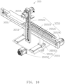
- the first hopper driver 3552 includes a slide rail 35521, a fixing pillar 35522, a first connecting member, and a first driver 35524.
- the fixing pillar 35522 is slidably connected to the slide rail 35521 and perpendicular to the slide rail 35521.
- the connecting member is connected to the fixing pillar 35522 and the first driver 35524.
- the first driver 35524 is used to drive the connecting member to move back and forth, thus driving the fixing pillar 35522 to slide along the slide rail 35521. As such, the hopper 3551 can move to the receiving position or the loading position.
- the first driver 35524 may be a step motor, and the connecting member may include a belt and a chain sleeved on the step motor.
- the fixing pillar 35522 includes a fixing block having a fixing slot. The belt is clamped in the fixing slot so that the fixing pillar 35522 is fixed to the belt. Thus, the fixing pillar 35522 can move together with the belt.
- An end of the chain is fixed on a top surface of the slide rail 35521, and the other end of the chain is connected to the fixing pillar 35522 through a fixing sheet.
- the chain is used to limit a moving length of the fixing pillar 35522 when the fixing pillar 35522 moves along the slide rail 35521.
- the components and operation principle of the second hopper 3551 driver are similar to those of the first hopper driver 3552, which will not be described.
- the transfer device 355 further includes a fourth hopper driver 3555.
- the fourth hopper driver 3555 is connected to the first hopper driver 3552, and is used to drive the hopper 3551 to move along a front and rear direction perpendicular to the horizontal and vertical directions between a first front and rear coordinate (Y 1 ) close to the reaction device 353 and a second front and rear coordinate (Y 2 ) away from the reaction device 353.
- the hopper 3551 when being at the first front and rear coordinate, is used to receive the biochip from the reaction vessel 3531 at the receiving position or discharge the biochip at the loading position.
- the fourth hopper driver 3555 includes a base 35551, a power member 35552, and a slide member 35553.
- the slide member 35553 is slidably connected to the base 35551 and further connected to the first hopper driver 3552.
- the power member 35552 is used to drive the slide member 35553 to slide forward and backward on the base 35551.
- the sliding of slide rail 35521 on the base 35551 is realized through a connection between slide slot and slide rail 35521.
- the synthesis apparatus 35 further includes a discharge sensor 356 and a first recovery vessel 357.
- the sorting device 354 further includes a second sorting assembly 3542.
- the transfer device 355 further includes a negative pressure reflux device (not shown) and a reflux storage device 3556.
- the discharge sensor 356 is located on a side of the recognition device 352 away from the first sorting assembly 3541, and is used to sense whether the biochip is transported to a preset position and then transmit a discharge sensing information generated therefrom to the control device 34.
- the second sorting assembly 3542 is located between the discharge sensor 356 and the recognition device 352, and corresponds to the first recovery vessel 357.
- the control device 34 is also used to determine whether an interval between the times at which two adjacent biochips are detected is less than a preset time according to the discharge sensing information. When the interval between the times at which two adjacent biochips are detected is less than the preset time, the control device 34 is used to control the second sorting assembly 3542 to sort the biochip to the first recovery vessel 357. When the interval between the times at which two adjacent biochips are detected is less than the preset time, a distance between the two biochips is indicated to be small.
- the biochip close to the previous biochip is sorted to the first recovery vessel 357 through the second sorting assembly 3542, which can avoid that the first sorting assembly 3541 cannot timely sort the two biochips for performing the same current synthesis reaction into the same reaction vessel 3531 due to the small distance between the biochips. At the same time, it can also avoid that the first sorting assembly 3541 mistakenly sorts two biochips for performing different current synthesis reactions into the same reaction vessel 3531 due to the mall distance between the biochips.
- the structure of the second sorting assembly 3542 is the same as that of the first sorting assembly 3541, which will not be repeated.
- the negative pressure reflux device is connected to the first recovery vessel 357, and is used to transport each biochip in the first recovery vessel 357 to the reflux storage device 3556 when being driven by the control device 34.
- the reflux storage device 3556 is located above the feeding device 351, and is used to place that has been transported to the reflux storage device 3556 to the feeding device 351.
- the reflux storage device 3556 includes a storage portion 35561 with a movable door 35561a, and also includes a cylinder 35562.
- the storage portion 35561 is used to store the biochip transported by the negative pressure reflux device.
- the cylinder 35562 is used to drive the movable door 35561a to open and close when controlled by the control device 34. When the movable door 35561a is opened, the biochip can drop from the storage portion 35561 to the feeding device 351.
- the synthesis apparatus 35 further includes a residue sensor 358 and a second recovery vessel 359.
- the residue sensor 358 is located at an end of the first sorting assemblies 3541 away from the recognition device 352, and is used to sense whether a biochip has been transported to a predetermined position and transmit a residue sensing information generated therefrom to the control device 34.
- the second recovery vessel 359 is located at an end of the transporting assembly 3511 away from the feeding device 351, and is used to receive the biochip residual from the transporting assembly 3511 that has not been successfully sorted.
- the biochip which is not successfully blown to the storage device 35414 due to the insufficient gas supply of the air supply device 35413 and still be placed on the transporting assembly 3511, can be ensured to be recycled.
- the biochip is placed on the belt of the transporting assembly 3511.
- the second recovery vessel 359 is located at an end of the traveling route of the belt, and is used to receive each biochip that has been transported to the end of the traveling route of the belt.
- the negative pressure reflux device is further connected to the second recovery vessel 359, and is used to transport the biochip in the second recovery vessel 359 to the reflux storage device 3556 when controlled by the control device 34.
- the control device controls the negative pressure reflux device to transport the biochip located in the second recovery vessel 359 to the reflux storage device 3556 when the number of the residual biochips reaches a preset number. Therefore, when the sorting device 354 fails to successfully sort the biochip into the corresponding reaction vessel 3531, the biochip can successively pass the second recovery vessel 359, the negative pressure reflux device, and the reflux storage device 3556 to the feeding device 351 again, so that the biochip can be transported to the transporting assembly 3511 for the next sorting.
- the synthesis apparatus 35 further includes a waste recovery vessel 35a and a finished material recovery vessel 35b.
- the sorting device 354 further includes a third sorting assembly 3543 and a fourth sorting assembly 3544.
- the third sorting assembly 3543 is located between the recognition device 352 and the first sorting assembly 3541, and corresponds to the waste recovery vessel 35a.
- the control device 34 determines whether the biochip is a waste according to the identification information. When the biochip is a waste and is transported to the third sorting assembly 3543, the control device 34 controls the third sorting assembly 3543 to sort the biochip to the waste recovery vessel 35a.
- the fourth sorting assembly 3544 is located between the recognition device 352 and the first sorting assembly 3541, and corresponds to the finished material recovery vessel 35b.
- the control device 34 determines whether the biochip completes all synthesis reactions according to the identification information. When the biochip completes all synthesis reactions and is transported to the fourth sorting assembly 3544, the control device 34 controls the fourth sorting assembly 3544 to sort the biochip to the finished material recovery vessel 35b.
- the structure of each of the third sorting assembly 3543 and the fourth sorting assembly 3544 is the same as that of the first sorting assembly 3541, which will not be repeated.
- FIG. 12 a flowchart of a synthesis method of biomacromolecules is illustrated, which includes the following steps.
- Step S110 a number of biochips are transport by a transporting assembly.
- a side of the transporting assembly is provided with a number of first sorting assemblies corresponding to a number of reaction vessels, a fourth sorting assembly, and a finished material recovery vessel corresponding to the fourth sorting assembly.
- Step S120 an identification of each biochip located on the transporting assembly is identified, and a corresponding identification information is generated.
- Step S130 a synthesis sequence of the biochip and a current synthesis reaction are determined according to the identification information.
- Step S140 when the biochip is transported to a first sorting assembly and the first sorting assembly corresponds to the reaction vessel for performing the current synthesis reaction, the corresponding first sorting assembly is controlled to sort the biochip to the corresponding reaction vessel.
- Step S150 the synthesis reaction is performed in the reaction vessel.
- Step S160 whether the biochip has completed all synthesis reactions is determined according to the identification information. If all synthesis reactions are completed, the procedure goes to step S170; otherwise, the procedure goes to step S180.
- Step S170 the fourth sorting assembly is controlled to sort the biochip to the finished material recovery vessel, and the procedure returns back to step S110.
- Step S180 the biochip in the reaction vessel that has completed the synthesis reaction is transferred to the transporting assembly.
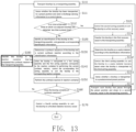
- the synthesis method of biomacromolecules further includes step S111 before the step S120, at which whether the biochip has been transported to a preset position is sensed, and a discharge sensing information is generated and sent to the control device. Accordingly, a side of the transporting assembly is further provided with a second sorting assembly and a first recovery vessel corresponding to the second sorting assembly.
- the synthesis method of biomacromolecules further includes the following steps S112 to S113.
- Step S112 whether an interval between the times at which two adjacent biochips are detected is less than a preset time is determined according to the discharge sensing information. When it is less than the preset time, the procedure goes to step S113; otherwise, the procedure goes to step S120.
- Step S113 the second sorting assembly is controlled to sort the biochip to the first recovery vessel, and the procedure goes to step S114 after completing the step S113.
- Step S114 each biochip in the first recovery vessel is transferred to the transporting assembly, and the procedure returns to the step S110.
- the biomacromolecule synthesis method further includes step S131 that is executed simultaneously to the step S130.
- the biochip is determined as a waste according to the identification information.
- a side of the transporting assembly is further provided with a third sorting assembly and a waste recovery vessel corresponding to the third sorting assembly.
- the synthesis method of biomacromolecules further includes the following step S132.
- Step S132 the third sorting assembly is controlled to sort the biochip to the waste recovery vessel when the biochip is transported to the third sorting assembly.
- the synthesis method of biomacromolecules further includes step S133, at which whether a biochip is transported to a predetermined position is sensed. Accordingly, an end of the transporting assembly is provided with a second recovery vessel.
- the synthesis method of biomacromolecules further includes step S134 after the step S133, at which each biochip that passes through the predetermined position and drops to the second recovery vessel is transported to the transporting assembly, and the procedure returns to the step S110.
- the synthesizer and the synthesis method multiple biochips placed on the transporting assembly can be simultaneously sorted by the first sorting assemblies arranged on a side of the transporting assembly, which improves the sorting efficiency of the biochips and shortening the synthesis cycle.
- the biochip since the reaction vessels correspond to the first sorting assemblies, the biochip may be sorted to the corresponding reaction vessel according to the identification information of the biochip.
- the modified or newly added synthesis sequence may be adapted by changing the sorting order, so as to achieve a higher degree of freedom of synthesis.
Landscapes
- Chemical & Material Sciences (AREA)
- Organic Chemistry (AREA)
- Health & Medical Sciences (AREA)
- General Health & Medical Sciences (AREA)
- Life Sciences & Earth Sciences (AREA)
- Biochemistry (AREA)
- Analytical Chemistry (AREA)
- Chemical Kinetics & Catalysis (AREA)
- Physics & Mathematics (AREA)
- General Physics & Mathematics (AREA)
- Immunology (AREA)
- Pathology (AREA)
- Molecular Biology (AREA)
- Genetics & Genomics (AREA)
- Biotechnology (AREA)
- Engineering & Computer Science (AREA)
- Dispersion Chemistry (AREA)
- Hematology (AREA)
- Clinical Laboratory Science (AREA)
- Apparatus Associated With Microorganisms And Enzymes (AREA)
- Physical Or Chemical Processes And Apparatus (AREA)
Abstract
Description
- The subject matter relates to synthesis of biomacromolecules, and more particularly, to a synthesis apparatus, a synthesizer, and a synthesis method of biomacromolecules.
- Common biomacromolecules include proteins, nucleic acids (DNA, RNA, etc.), and carbohydrates. Most biomacromolecules are polymerized from simple constituent structures. The constituent unit of protein is amino acid, and the constituent unit of nucleic acid is nucleotide. The biomacromolecules can be synthesized from simple structures within organisms. If the biomacromolecules need to be synthesized artificially, a special instrument such as a synthesizer, is needed.
- Taking DNA synthesis as an example, the DNA synthesis refers to the artificial connection of deoxynucleotides one by one to obtain DNA strands according to a preset sequence of nucleotides. For example, a single-stranded DNA sequence CGTGCA can be synthesized from a left side to a right side.
- The existing synthesizer includes fixing an oligonucleotide single strand on a glass synthesis column, immersing the synthesis column in a container, and then adding various corresponding nucleotide reagents to the container, so that the single-stranded oligonucleotides can be continuously extended according to a required sequence. However, the principle and process of such synthesizer is complex, the synthesis flux is low, and the consumption of reagents is large. In addition, during the synthesis process of biomacromolecules, the synthesis cycle is long, and the target synthesis task cannot be changed.
- To overcome at least a portion of the above shortcomings, a synthesis apparatus, a synthesizer, and a synthesis method are needed.
- A synthesis apparatus for synthesizing biomacromolecules, which includes a feeding device, a recognition device, a reaction device, a sorting device, and a transfer device. The feeding device includes a transporting assembly configured to simultaneously transport a plurality of biochips. The recognition device is configured to identify an identification of each of the biochips located on the transporting assembly and feed back an identification information to a control device. The reaction device includes a plurality of reaction vessels in which synthesis reactions are performed on the biochips. The sorting device includes a plurality of first sorting assemblies located on a side of the transporting assembly and corresponding to the reaction vessels, the first sorting assemblies are configured to sort the biochips located on the transporting assembly to the reaction vessels, and each of the reaction vessels corresponding to a current synthesis reaction performed on a respective one of the biochips when controlled by the control device. The transfer device is configured to transfer the biochips in the reaction vessels to the feeding device.
- Furthermore, each of the first sorting assemblies includes a first site sensor and a first selection device corresponding to the first site sensor, the first site sensor is configured to sense whether one of the biochips has been transported to the first site sensor and send a site sensing information to the control device, the first selection device is configured to transfer the one of the biochips to a respective one of the reaction vessels when controlled by the control device.
- Furthermore, the first selection device includes a gas supply device on a side of the transporting assembly and a storage device on another side of the transporting assembly, the gas supply device is configured to blow the one of the biochips to the storage device when controlled by the control device, the storage device is configured to transfer the one of the biochips to a respective one of the reaction vessels.
- Furthermore, the synthesis apparatus further includes a discharge sensor and a first recovery vessel, wherein the sorting device further includes a second sorting assembly; the discharge sensor is located on a side of the recognition device away from the first sorting assemblies, and is configured to sense whether one of the biochips has been transported to a preset position and transmit a discharge sensing information to the control device; the second sorting assembly is located between the discharge sensor and the recognition device and corresponds to the first recovery vessel, the second sorting assembly is configured to sort the one of the biochips to the first recovery vessel when controlled by the control device.
- Furthermore, the transfer device further includes a negative pressure reflux device and a reflux storage device; the negative pressure reflux device is connected to the first recovery vessel, and is configured to transport the one of the biochips in the first recovery vessel to the reflux storage device when controlled by the control device; the reflux storage device is configured to place the reflux storage device to the feeding device.
- Furthermore, the synthesis apparatus further includes a residue sensor and a second recovery vessel, wherein the residue sensor is located at an end of the first sorting assemblies away from the recognition device, and is configured to sense whether one of the biochips has been sent to a predetermined position and transmit a residue sensing information to the control device; the second recovery vessel is placed at an end of the transporting assembly away from the feeding device, and is configured to receive one of the biochips from the transporting assembly which is not successfully sorted; the negative pressure reflux device is further configured to transport the one of biochips in the second recovery vessel to the reflux storage device when controlled by the control device.
- Furthermore, the synthesis apparatus further includes a waste recovery vessel, wherein the sorting device further includes a third sorting assembly, the third sorting assembly is located between the recognition device and the first sorting assemblies and corresponds to the waste recovery vessel; the third sorting assembly is configured to sort one of the biochips which is determined as a waste into the waste recovery vessel when controlled by the control device.
- Furthermore, the synthesis apparatus further includes a finished material recovery vessel, wherein the sorting device further includes a fourth sorting assembly, the fourth sorting assembly is located between the recognition device and the first sorting assemblies and corresponds to the finished material recovery vessel; the fourth sorting assembly is configured to sort one of the biochips which completes all synthesis reactions to the finished material recovery vessel when controlled by the control device.
- A synthesizer is provided, which includes the above-mentioned synthesis apparatus, a control device configured to control the synthesis apparatus, and an input member and an output member each connected to the control device. The control device is configured to execute corresponding programs to control the synthesis apparatus to operate according to a content input from the input member, and display relevant information on the output member.
- A synthesis method of biomacromolecules is provided, which includes:
- transporting, by a transporting assembly, a plurality of biochips, wherein a plurality of first sorting assemblies corresponding to a plurality of reaction vessels is arranged on a side of the transporting assembly;
- identifying an identification of each of the biochips located on the transporting assembly and generating an identification information accordingly;
- determining a synthesis sequence and a current synthesis reaction of each of the biochips according to the identification information;
- when one of the biochips has been transported to one of the first sorting assemblies corresponding to one of the reaction vessels for performing the current synthesis reaction, controlling the one of the first sorting assemblies to sort the one of the biochips to the corresponding one of the reaction vessels;
- performing the synthesis reaction in the corresponding one of the reaction vessels.
- In the synthesizer and the synthesis method, multiple biochips placed on the transporting assembly can be simultaneously sorted by the first sorting assemblies arranged on a side of the transporting assembly, which improves the sorting efficiency of the biochips and shortening the synthesis cycle. In addition, since the reaction vessels correspond to the first sorting assemblies, the biochip may be sorted to the corresponding reaction vessel according to the identification information of the biochip. During the synthesis process, even when the synthesis sequence of the biochip is modified or added, the modified or newly added synthesis sequence may be adapted by changing the sorting order, so as to achieve a higher degree of freedom of synthesis.
-
-
FIG. 1 is a diagrammatic view showing oligonucleotides synthesized by a biochip with identification according to the present disclosure. -
FIG. 2 is a diagrammatic view showing an appearance of a synthesizer according to the present disclosure. -
FIG. 3 is a diagram of components of the synthesizer ofFIG. 2 . -
FIG. 4 is a stereoscopic view of the synthesizer ofFIG. 2 , when a housing thereof is partially removed. -
FIG. 5 is a stereoscopic view showing the synthesis apparatus ofFIG. 4 from another angle. -
FIG. 6 is a stereoscopic view of the synthesis apparatus ofFIG. 5 , when a transfer device thereof is partially removed. -
FIG. 7 is a stereoscopic view showing the synthesis apparatus ofFIG. 6 from another angle. -
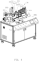
FIG. 8 is a stereoscopic view of a reaction device ofFIG. 5 , when the reaction device is rotated by an angle. -
FIG. 9 is a stereoscopic view showing a storage device in the synthesis apparatus ofFIG. 6 without blocking a biochip. -
FIG. 10 is a stereoscopic view partially showing the transfer device in the synthesis apparatus ofFIG. 5 . -
FIG. 11 is a stereoscopic view showing the transfer device ofFIG. 10 from another angle. -
FIG. 12 is a flowchart of a synthesis method according to an embodiment of the present disclosure. -
FIG. 13 is a flowchart of a synthesis method according to another embodiment of the present disclosure. - The following specific embodiments will further explain the application in combination with the above drawings.
- Implementations of the application will now be described, by way of embodiments only, with reference to the drawings.
- Symbol description of main components:
oligonucleotide single strand 10;biochip 20;identification 21;synthesizer 30;housing 31;display 32;input member 33;control device 34;synthesis apparatus 35;channel 36;feeding device 351;recognition device 352;reaction device 353;sorting device 354;transfer device 355;transporting assembly 3511;guide rail 3512;conveying belt 3513;first step motor 3514;bottom plate 35121;cover plate 35122;limit plate 35123;feeding groove 35151; vibratingdisc 3515;guide member 3516; vibratingrail 35152;image capturing member 3521;reaction vessel 3531;synthesis reaction column 35311;sealing cover 35312; opening andclosing driver 3532;positioning body 3533;container driver 3534;first sorting assembly 3541;site sensor 35411; selection device 35412;gas supply device 35413;storage device 35414;nozzle 35415;switch 35416;storage bin 35417;lifting member 35418;lifting driver 35419;second step motor 35419a;screw rod 35419b;stopper 35418a; hopper 3551;first hopper driver 3552;second hopper driver 3553;third hopper driver 3554;slide rail 35521;fixing pillar 35522; first connectingmember 35523;first driver 35524;fourth hopper driver 3555;base 35551;power member 35552;slide member 35553;discharge sensor 356;first recovery vessel 357;second sorting assembly 3542;reflux storage device 3556;residue sensor 358,second recovery vessel 359;storage portion 35561;waste recovery vessel 35a; finished material recovery vessel 35b;third sorting assembly 3543;fourth sorting assembly 3544. - Implementations of the present disclosure will now be described, by way of embodiments only, with reference to the drawings. The described embodiments are only some embodiments of the present disclosure, rather than all the embodiments. Based on the embodiments of the present disclosure, other embodiments obtained by ordinary skilled in the art without creative work fall within the scope of the claims.
- It should be noted that when a component is referred to as being or "mounted on" another component, the component can be directly on another component or a middle component may exist therebetween. When a component is considered to be "arranged on" another component, the component can be directly on another component or a middle component may exist therebetween.
- Unless otherwise defined, all technical terms used herein have the same meaning as commonly understood by one of ordinary skill in the art. The technical terms used herein are not to be considered as limiting the scope of the embodiments. The term "and/or" as used herein means any combinations of one or more related listed items.
- A synthesizer provided by the present disclosure may be used to synthesize biomacromolecules, including but not limited to proteins, nucleic acids (DNA, RNA, etc.), carbohydrates, etc. A carrier for the synthesis of the biomacromolecules is a biochip. The biomacromolecules are fixed on a surface of the biochip, and are continuously extended in the synthesizer according to a required sequence to obtain a required macromolecule structure.
- Referring to
FIG. 1 , taking the synthesis of an oligonucleotide primer as an example, oligonucleotide single strands 10 are fixed on the surface of thebiochip 20. A number of oligonucleotide single strands may be fixed on the surface of biochip 20 (two oligonucleotide single strands are shown in the figure). Each oligonucleotide single strand is continuously extended by the synthesizer of the present disclosure according to the required sequence. Before the synthesizer of the present disclosure is used, a small segment of short strand of the oligonucleotide single strand may be pre-fixed on the surface of thebiochip 20. Or, a specific biochemical adaptor may be arranged on the surface of thebiochip 20, and the required biomacromolecule structure may be obtained by continuously extending the pre-fixed short strand of the oligonucleotide single strand or the specific biochemical adaptor. Anidentification 21 is provided on thebiochip 20, which is shown in the shaded portion of the figure. Theidentification 21 is the identity of the correspondingbiochip 20, which is used to distinguish thebiochip 20 fromother biochips 20. Theidentification 21 may be represented by a two-dimensional code, a barcode, an RFID tag, or other existing methods. In other embodiments, theidentification 21 may also be arranged on another specific location or several other specific locations of thebiochip 20. - Referring to
FIGS. 2 and3 , thesynthesizer 30 is used to synthesize the biomacromolecules. In an embodiment, taking the synthesis of an oligonucleotide primer as an example, thesynthesizer 30 includes ahousing 31, and adisplay 32 and aninput member 33 both fixed on the housing . In an embodiment, thedisplay 32 and theinput member 33 are integrated as a touch screen display. It may be understood that theinput member 33 may also be set separately from thedisplay 32, which includes a keyboard, a mouse, or another input device. Thesynthesizer 30 further includes acontrol device 34 and asynthesis apparatus 35 located in thehousing 31. Thecontrol device 34 is communicated with each of thedisplay 32, theinput component 33, and thesynthesis apparatus 35, and may be as large as a server, a host, or as small as a chip. Thecontrol device 34 is used to execute corresponding programs according to a content input by theinput member 33, thereby controlling thesynthesis apparatus 35 and display relevant information (such as abnormal information, completion information, etc.) on thedisplay 32. Thecontrol device 34 may be arranged inside thehousing 31 or outside thehousing 31, and may be a local control device or a remote control device. The content input by theinput member 33 may be used to set a synthesis reaction required for eachbiochip 20 or to define abnormal characteristics of an abnormal biochip 20 (for example, the identification is unrecognizable, etc.). At least onechannel 36 connecting the inside of thesynthesizer 30 is defined on thehousing 31. The internal structure of thesynthesizer 30 may be touched through thechannel 36, and thebiochip 20 used for the synthesis of the oligonucleotide primer may also be placed into thesynthesizer 30 through thechannel 36. - Referring to
FIGS. 4 and5 , thesynthesis apparatus 35 includes afeeding device 351 for transporting the biochips, arecognition device 352 for recognizing the biochips, areaction device 353 for performing the synthesis reaction on the biochips, asorting device 354 for sorting the biochips, and atransfer device 355 for transferring the biochips. - Referring to
FIGS. 6 and7 , thefeeding device 351 includes a transportingassembly 3511 for simultaneously transporting a number of biochips. In an embodiment, the transportingassembly 3511 includes aguide rail 3512, a conveyingbelt 3513, and afirst step motor 3514. The conveyingbelt 3513 is wound on theguide rail 3512 along an extended direction of theguide rail 3512, and further sleeved on an output shaft of thefirst step motor 3514. The conveyingbelt 3513 is used to move along theguide rail 3512 when driven by thefirst step motor 3514, thereby transporting the biochips on the conveyingbelt 3513. Specifically, theguide rail 3512 includes abottom plate 35121, atransparent cover plate 35122, and twolimit plates 35123 connected between thebottom plate 35121 and thecover plate 35122 and opposite to each other. Thefirst step motor 3514 is located at an end of thebottom plate 35121 away from the transportingassembly 3511. The conveyingbelt 3513 is located between the twolimit plates 35123, one portion of the conveyingbelt 3513 is located between thebottom plate 35121 and thecover plate 35122, and the remaining portion is located outside theguide rail 3512. - The
feeding device 351 further includes a vibratingdisc 3515 with a feedinggroove 35151 and a discharge port (not shown in the figure), and further includes ahollow guide member 3516. Theguide member 3516 is communicated with the discharge port of the vibratingdisc 3515. A vibratingrail 35152 is arranged in the vibratingdisc 3515. The vibratingrail 35152 is in a circular and progressive shape, which is used to orderly arrange the biochips that enter thefeeding groove 35151 and output the biochips to theguide member 3516. An end of theguide member 3516 away from thevibration disk 3515 is located above the transportingassembly 3511, which allows each biochip that is output to theguide member 3516 to slide onto the transportingassembly 3511 under its own gravity. - The
recognition device 352 is used to identify the identification of each biochip located on the conveyingbelt 3513, and feed back an identification information generated therefrom to the control device. - The
recognition device 352 includes animage capturing member 3521 and an image recognition member (not shown). Theimage capturing member 3521 is located above the transportingassembly 3511, and is used to capture the image of each biochips transported by the transportingassembly 3511. The image recognition member is used to identify the identification of the biochip according to the image of the biochip, and send the generated identification information to thecontrol device 34. It may be understood that the image recognition member may also be set in thecontrol device 34. Theimage capturing member 3521 transmits the captured image of the biochip to thecontrol device 34. Thecontrol device 34 recognizes the identification of the biochip according to the image of the biochip, thereby obtaining the identification information. - Referring to
FIGS. 5 and8 , thereaction device 353 is located on a side of therecognition device 352 away from thefeeding device 351, and includes a number ofreaction vessels 3531. Eachreaction vessel 3531 is used for the synthesis reaction or the cleaning of the biochip located in thereaction vessel 3531. Eachreaction vessel 3531 is for completing a different synthesis reaction. For example, the number ofreaction vessels 3531 is four. The fourreaction vessels 3531 are respectively used for the synthesis of adenine (A), thymine (T), cytosine (C), and guanine (G). - Specifically, each
reaction vessel 3531 includes asynthesis reaction column 35311 and a sealingcover 35312 that may be opened and closed with respect to thesynthesis reaction column 35311. The sealingcover 35312 is used to seal thesynthesis reaction column 35311 to complete the synthesis reaction on the biochip. When the sealingcover 35312 does not cover thesynthesis reaction column 35311, the biochip can be placed into thesynthesis reaction column 35311. Thereaction device 353 further includes an opening andclosing driver 3532. The opening andclosing driver 3532 is connected to the sealingcover 35312, and is used to drive the sealingcover 35312 to move upwards and downwards, causing the sealingcover 35312 to leave or seal thesynthesis reaction column 35311. - In an embodiment, the
reaction vessels 3531 can rotate between a first position and a second position. The first position is a position for receiving the biochip. The second position is a position for discharging the biochip. Specifically, thereaction device 353 further includes apositioning body 3533 and acontainer driver 3534 connected to thepositioning body 3533. Thereaction vessels 3531 are arranged side-by-side and fixed on thepositioning body 3533. Thecontainer driver 3534 is used to drive thepositioning body 3533 to rotate by a preset angle along a first direction according to a rotation command from thecontrol device 34, and further rotate along the opposite direction of the first direction back to its original position at a preset time after thepositioning body 3533 rotates by the preset angle. Thus, the biochips are discharged when thereaction vessels 3531 rotate by the preset angle, and thereaction vessels 3531 can further receive the biochips after discharging the biochips. Thecontrol device 34 sends the rotation command to thecontainer driver 3534 when thereaction devices 353 complete the synthesis reaction. The position of thepositioning body 3533 after rotating by the preset angle along the first direction is the second position. The position of thepositioning body 3533 after rotating along the direction opposite of the first direction is the first position. - Referring to
FIGS. 6 and7 , thesorting device 354 includes a number offirst sorting assemblies 3541. Thefirst sorting assemblies 3541 are located on a side of the transportingassembly 3511 and correspond to thereaction vessels 3531. Thecontrol device 34 determines the synthesis sequence of each biochip and the current synthesis reaction according to the identification information. When one biochip is transported to thefirst sorting assembly 3541 corresponding to thereaction vessel 3531 for performing the current synthesis reactions, thecontrol device 34 controls thefirst sorting assembly 3541 to sort the biochip to thecorresponding reaction vessel 3531. - In an embodiment, each
first sorting assembly 3541 includes asite sensor 35411 and a selection device (not shown) corresponding to thesite sensor 35411. Thesite sensor 35411 is located above the selection device, and is used to sense whether a biochip has been transported to thesite sensor 35411 and send a site sensing information to thecontrol device 34. Thecontrol device 34 determines the synthesis sequence of the current biochip and the current synthesis reaction according to the identification information of the current biochip, and determines according to the current synthesis reaction whether the biochip sensed by thesite sensor 35411 is sorted by the selection device corresponding to thesite sensor 35411. When thesite sensor 35411 senses that the biochip is sorted by the selection device corresponding to thesite sensor 35411, a sorting command is sent to the selection device corresponding to thesite sensor 35411. The selection device is used to transfer the biochip to thereaction vessel 3531 according to the sorting command. - To illustrate the working process of the
first sorting assemblies 3541, thefirst sorting assemblies 3541 are set to be corresponding to thereaction vessels 3531 respectively for adenine synthesis, thymine synthesis, cytosine synthesis, and guanine synthesis along the direction away from therecognition device 352. One biochip is transported to therecognition device 352, which recognizes the biochip. For example, thecontrol device 34 determines that the current synthesis reaction performed on the biochip is cytosine synthesis reaction according to the identification information. When the biochip is transported to thesite sensor 35411 nearest to the recognition device 352 (hereinafter, adenine synthesis site sensor for simplicity), the adenine synthesis site sensor detects the biochip. However, the biochip is subjected to a cytosine synthesis reaction instead of the adenine synthesis reaction corresponding to the adenine synthesis site sensor. Thecontrol device 34 will not send the sorting command to the selection device corresponding to the adenine synthesis site sensor. As such, the biochip will continue to be transported to the next site sensor (hereinafter, thymine synthesis site sensor for simplicity). Similarly, thecontrol device 34 will not send the sorting command to the selection device corresponding to the thymine synthesis position sensor. The biochip continues to be transported to the next site sensor (hereinafter, cytosine synthesis site sensor for simplicity). When the cytosine synthesis site sensor senses the biochip, since the synthesis reaction to be performed on the biochip is the cytosine synthesis reaction corresponding to the cytosine synthesis site sensor, thecontrol device 34 sends the sorting command to the selection device corresponding to the cytosine synthesis site sensor. Thus, the selection device sorts the biochip to thecorresponding reaction vessel 3531. - In an embodiment, the
first sorting assembly 3541 includes a selection device, but does not include the site sensor. Thecontrol device 34 determines the position of the biochip according to a distance between the selection device and therecognition device 352, a time for obtaining the identification information of the biochip, and a speed of the transportingassembly 3511 for transporting the biochip, thereby determining whether the biochip has been transported to the corresponding selection device. - In an embodiment, the selection device includes a
gas supply device 35413 on a side of the transporting assembly and astorage device 35414 on another side of the transporting assembly. Thegas supply device 35413 is used to blow the corresponding biochip to thestorage device 35414 according to the sorting command from thecontrol device 34. Thestorage device 35414 is used to transfer the biochip to thecorresponding reaction vessel 3531. - Specifically, the
gas supply device 35413 includes ahollow nozzle 35415, a gas supply pipeline (not shown), and aswitch 35416. Thehollow nozzle 35415 is connected to the gas supply pipeline. The gas supply pipeline is used to receive a compressed gas. Thelimit plate 35123 of the transportingassembly 3511 forms a throughhole 35124 aligned with the hollow nozzle. Theswitch 35416 is used to control the gas supply pipeline to supply the gas to thenozzle 35415 according to the sorting command from thecontrol device 34. When theswitch 35416 is turned on, the compressed gas in the gas supply pipeline passes through thenozzle 35415 and then blows the biochip to thecorresponding storage device 35414 through the throughhole 35124. In an embodiment, theswitch 35416 is a solenoid valve. - Referring to
FIG. 9 , thestorage device 35414 includes a number ofstorage bins 35417 fixed on the transporting assembly. Eachstorage bin 35417 includes aninlet 35417a and anoutlet 35417b. Theinlet 35417a faces onefirst sorting assembly 3541, and theoutlet 35417b faces onereaction vessel 3531. The biochip drops to thereaction vessel 3531 after passing through theinlet 35417a andoutlet 35417b, so that the synthesis reaction is then performed in thereaction vessel 3531. Thestorage device 35414 further includes a liftingmember 35418 and a liftingdriver 35419. The liftingdriver 35419 is mechanically connected to the liftingmember 35418 and further communicated with thecontrol device 34. The liftingdriver 35419 is used to drive the liftingmember 35418 to move toward or away from thestorage bin 35417 according to a lifting command from thecontrol device 34. The liftingmember 35418 is used to block the biochip located in thestorage bin 35417 during the movement, and also allow the biochip to drop to thereaction vessel 3531 through theoutlet 35417b. - In an embodiment, the lifting
drive 35419 includes asecond step motor 35419a and ascrew rod 35419b connected to thesecond step motor 35419a. The liftingmember 35418 is movably sleeved on thescrew rod 35419b, and the rotation of thescrew rod 35419b drives the liftingmember 35418 to move upwards and downwards. Thecontrol device 34 records the number of sorting by the first sorting assembly 3541 (i.e., the number of sorted biochips), and sends the lifting command to the liftingdriver 35419 when the number of sorting reaches a preset number. Then, the liftingdriver 35419 drives the liftingmember 35418 to move upwards and downwards. The liftingmember 35418 includes at least one suspendedstopper 35418a. Thestopper 35418a is used to block the biochip in thestorage bin 35417 when the liftingmember 35418 move downwards, and also allow the biochip to drop to thereaction vessel 3531 through theoutlet 35417b when the liftingmember 35418 move upwards. In an embodiment, a top surface of thestorage bin 35417 has anopening 35417c at an end of theoutlet 35417b. The stopper is used to be located in theopening 35417c to block the biochip. In an embodiment, the number ofstorage bins 35417 is four. The liftingmember 35418 includes fourstoppers 35418a. The fourstoppers 35418a are respectively used to block the biochips in the fourstorage bins 35417. It may be understood that the fourstoppers 35418a may also be set on four separated liftingmembers 35418, and the four liftingmembers 35418 are respectively connected to four liftingdrivers 35419. Thecontrol device 34 is used to control each liftingdriver 35419 to drive the liftingmember 35418 to move according to the number of sorting of eachfirst sorting assembly 3541, so as to control the four liftingmember 35418a to block the biochips. - The
transfer device 355 is used to transfer the biochip in thereaction vessel 3531 that completes the synthesis reaction to thefeeding device 351 according to a transfer command from thecontrol device 34. Thecontrol device 34 sends the transfer instruction when the biochip in thereaction vessel 3531 completes the synthesis reaction. The biochip transferred to thefeeding device 351 by thetransfer device 355 is further transferred by the transportingassembly 3511 for the next sorting. As such, a base component is synthesized in each cycle until the biochip completes all synthesis tasks of the target synthesis sequence. - Referring to
FIG. 10 , thetransfer device 355 includes ahopper 3551, afirst hopper driver 3552, asecond hopper driver 3553 connected to thefirst hopper driver 3552, and athird hopper driver 3554 connected to thehopper 3551 and thesecond hopper driver 3553. Thefirst hopper driver 3552 is used to drive thehopper 3551 to move horizontally between a receiving position at a horizontal coordinate (X1) and a loading position at a horizontal coordinate (X2). Thesecond hopper driver 3553 is used to drive thehopper 3551 to move vertically between the receiving position at a vertical coordinate (Z1) and the loading position at a vertical coordinate (Z2). Thehopper 3551, when being located at the horizontal coordinate and the vertical coordinate of the receiving position, is used to receive the biochip discharged from thereaction vessel 3531. Thehopper 3551, when being located at the horizontal coordinate and the vertical coordinate of the loading position, is further used to discharge the biochip. The order that thehopper 3551 moves to the horizontal coordinate of the receiving position, the horizontal coordinate of the loading position, the vertical coordinate of the receiving position, and the vertical coordinate of the loading position, when being driven by of thefirst hopper driver 3552 and thesecond hopper driver 3553, is determined as needed. For example, for moving thehopper 3551 to the receiving position, thefirst hopper driver 3552 can first horizontally move thehopper 3551 from the loading position to the horizontal coordinate of the receiving position, and then thesecond hopper driver 3553 can vertically move thehopper 3551 down to the vertical coordinate of the receiving position. For example, thesecond hopper driver 3553 can first vertically move thehopper 3551 from the loading position down to the vertical coordinate of the receiving position, and then thefirst hopper driver 3552 can horizontally move thehopper 3551 to the horizontal coordinate of the receiving position. Thethird hopper driver 3554 is used to drive thehopper 3551 at the loading position to rotate. Thus, thehopper 3551 is switched between a horizontal state and a vertical state to receive the biochip from thereaction vessel 3531 and discharge the biochip to thefeeding device 351. - Specifically, the
first hopper driver 3552 includes aslide rail 35521, a fixingpillar 35522, a first connecting member, and afirst driver 35524. The fixingpillar 35522 is slidably connected to theslide rail 35521 and perpendicular to theslide rail 35521. The connecting member is connected to the fixingpillar 35522 and thefirst driver 35524. Thefirst driver 35524 is used to drive the connecting member to move back and forth, thus driving the fixingpillar 35522 to slide along theslide rail 35521. As such, thehopper 3551 can move to the receiving position or the loading position. In an embodiment, thefirst driver 35524 may be a step motor, and the connecting member may include a belt and a chain sleeved on the step motor. The fixingpillar 35522 includes a fixing block having a fixing slot. The belt is clamped in the fixing slot so that the fixingpillar 35522 is fixed to the belt. Thus, the fixingpillar 35522 can move together with the belt. An end of the chain is fixed on a top surface of theslide rail 35521, and the other end of the chain is connected to the fixingpillar 35522 through a fixing sheet. The chain is used to limit a moving length of the fixingpillar 35522 when the fixingpillar 35522 moves along theslide rail 35521. The components and operation principle of thesecond hopper 3551 driver are similar to those of thefirst hopper driver 3552, which will not be described. - In an embodiment, the
transfer device 355 further includes afourth hopper driver 3555. Thefourth hopper driver 3555 is connected to thefirst hopper driver 3552, and is used to drive thehopper 3551 to move along a front and rear direction perpendicular to the horizontal and vertical directions between a first front and rear coordinate (Y1) close to thereaction device 353 and a second front and rear coordinate (Y2) away from thereaction device 353. Thehopper 3551, when being at the first front and rear coordinate, is used to receive the biochip from thereaction vessel 3531 at the receiving position or discharge the biochip at the loading position. When thehopper 3551 moves from the first front and rear coordinate to the second front and rear coordinate, an enough distance exist between thehopper 3551 and thereaction device 353, which prevents thehopper 3551 from being blocked by the components between thereaction device 353 and thefeeding device 351. Specifically, thefourth hopper driver 3555 includes abase 35551, apower member 35552, and aslide member 35553. Theslide member 35553 is slidably connected to thebase 35551 and further connected to thefirst hopper driver 3552. Thepower member 35552 is used to drive theslide member 35553 to slide forward and backward on thebase 35551. The sliding ofslide rail 35521 on thebase 35551 is realized through a connection between slide slot andslide rail 35521. - Furthermore, referring to
FIG. 6 , thesynthesis apparatus 35 further includes adischarge sensor 356 and afirst recovery vessel 357. Thesorting device 354 further includes asecond sorting assembly 3542. Thetransfer device 355 further includes a negative pressure reflux device (not shown) and areflux storage device 3556. Thedischarge sensor 356 is located on a side of therecognition device 352 away from thefirst sorting assembly 3541, and is used to sense whether the biochip is transported to a preset position and then transmit a discharge sensing information generated therefrom to thecontrol device 34. Thesecond sorting assembly 3542 is located between thedischarge sensor 356 and therecognition device 352, and corresponds to thefirst recovery vessel 357. Thecontrol device 34 is also used to determine whether an interval between the times at which two adjacent biochips are detected is less than a preset time according to the discharge sensing information. When the interval between the times at which two adjacent biochips are detected is less than the preset time, thecontrol device 34 is used to control thesecond sorting assembly 3542 to sort the biochip to thefirst recovery vessel 357. When the interval between the times at which two adjacent biochips are detected is less than the preset time, a distance between the two biochips is indicated to be small. The biochip close to the previous biochip is sorted to thefirst recovery vessel 357 through thesecond sorting assembly 3542, which can avoid that thefirst sorting assembly 3541 cannot timely sort the two biochips for performing the same current synthesis reaction into thesame reaction vessel 3531 due to the small distance between the biochips. At the same time, it can also avoid that thefirst sorting assembly 3541 mistakenly sorts two biochips for performing different current synthesis reactions into thesame reaction vessel 3531 due to the mall distance between the biochips. In an embodiment, the structure of thesecond sorting assembly 3542 is the same as that of thefirst sorting assembly 3541, which will not be repeated. The negative pressure reflux device is connected to thefirst recovery vessel 357, and is used to transport each biochip in thefirst recovery vessel 357 to thereflux storage device 3556 when being driven by thecontrol device 34. Thereflux storage device 3556 is located above thefeeding device 351, and is used to place that has been transported to thereflux storage device 3556 to thefeeding device 351. - Referring to
FIG. 11 , specifically, thereflux storage device 3556 includes astorage portion 35561 with amovable door 35561a, and also includes acylinder 35562. Thestorage portion 35561 is used to store the biochip transported by the negative pressure reflux device. Thecylinder 35562 is used to drive themovable door 35561a to open and close when controlled by thecontrol device 34. When themovable door 35561a is opened, the biochip can drop from thestorage portion 35561 to thefeeding device 351. - Referring to
FIG. 6 , thesynthesis apparatus 35 further includes aresidue sensor 358 and asecond recovery vessel 359. Theresidue sensor 358 is located at an end of thefirst sorting assemblies 3541 away from therecognition device 352, and is used to sense whether a biochip has been transported to a predetermined position and transmit a residue sensing information generated therefrom to thecontrol device 34. Thesecond recovery vessel 359 is located at an end of the transportingassembly 3511 away from thefeeding device 351, and is used to receive the biochip residual from the transportingassembly 3511 that has not been successfully sorted. As such, the biochip, which is not successfully blown to thestorage device 35414 due to the insufficient gas supply of theair supply device 35413 and still be placed on the transportingassembly 3511, can be ensured to be recycled. In an embodiment, the biochip is placed on the belt of the transportingassembly 3511. Thesecond recovery vessel 359 is located at an end of the traveling route of the belt, and is used to receive each biochip that has been transported to the end of the traveling route of the belt. The negative pressure reflux device is further connected to thesecond recovery vessel 359, and is used to transport the biochip in thesecond recovery vessel 359 to thereflux storage device 3556 when controlled by thecontrol device 34. The control device controls the negative pressure reflux device to transport the biochip located in thesecond recovery vessel 359 to thereflux storage device 3556 when the number of the residual biochips reaches a preset number. Therefore, when thesorting device 354 fails to successfully sort the biochip into thecorresponding reaction vessel 3531, the biochip can successively pass thesecond recovery vessel 359, the negative pressure reflux device, and thereflux storage device 3556 to thefeeding device 351 again, so that the biochip can be transported to the transportingassembly 3511 for the next sorting. - The
synthesis apparatus 35 further includes awaste recovery vessel 35a and a finished material recovery vessel 35b. Thesorting device 354 further includes athird sorting assembly 3543 and afourth sorting assembly 3544. Thethird sorting assembly 3543 is located between therecognition device 352 and thefirst sorting assembly 3541, and corresponds to thewaste recovery vessel 35a. Thecontrol device 34 determines whether the biochip is a waste according to the identification information. When the biochip is a waste and is transported to thethird sorting assembly 3543, thecontrol device 34 controls thethird sorting assembly 3543 to sort the biochip to thewaste recovery vessel 35a. Thefourth sorting assembly 3544 is located between therecognition device 352 and thefirst sorting assembly 3541, and corresponds to the finished material recovery vessel 35b. Thecontrol device 34 determines whether the biochip completes all synthesis reactions according to the identification information. When the biochip completes all synthesis reactions and is transported to thefourth sorting assembly 3544, thecontrol device 34 controls thefourth sorting assembly 3544 to sort the biochip to the finished material recovery vessel 35b. In an embodiment, the structure of each of thethird sorting assembly 3543 and thefourth sorting assembly 3544 is the same as that of thefirst sorting assembly 3541, which will not be repeated. - Referring to
FIG. 12 , a flowchart of a synthesis method of biomacromolecules is illustrated, which includes the following steps. - Step S110, a number of biochips are transport by a transporting assembly. A side of the transporting assembly is provided with a number of first sorting assemblies corresponding to a number of reaction vessels, a fourth sorting assembly, and a finished material recovery vessel corresponding to the fourth sorting assembly.
- Step S120, an identification of each biochip located on the transporting assembly is identified, and a corresponding identification information is generated.
- Step S130, a synthesis sequence of the biochip and a current synthesis reaction are determined according to the identification information.
- Step S140, when the biochip is transported to a first sorting assembly and the first sorting assembly corresponds to the reaction vessel for performing the current synthesis reaction, the corresponding first sorting assembly is controlled to sort the biochip to the corresponding reaction vessel.
- Step S150, the synthesis reaction is performed in the reaction vessel.
- Step S160, whether the biochip has completed all synthesis reactions is determined according to the identification information. If all synthesis reactions are completed, the procedure goes to step S170; otherwise, the procedure goes to step S180.
- Step S170, the fourth sorting assembly is controlled to sort the biochip to the finished material recovery vessel, and the procedure returns back to step S110.
- Step S180, the biochip in the reaction vessel that has completed the synthesis reaction is transferred to the transporting assembly.
- Referring to
FIG. 13 , in another embodiment, besides the steps S110 to S180 mentioned above, the synthesis method of biomacromolecules further includes step S111 before the step S120, at which whether the biochip has been transported to a preset position is sensed, and a discharge sensing information is generated and sent to the control device. Accordingly, a side of the transporting assembly is further provided with a second sorting assembly and a first recovery vessel corresponding to the second sorting assembly. The synthesis method of biomacromolecules further includes the following steps S112 to S113. - Step S112, whether an interval between the times at which two adjacent biochips are detected is less than a preset time is determined according to the discharge sensing information. When it is less than the preset time, the procedure goes to step S113; otherwise, the procedure goes to step S120.
- Step S113, the second sorting assembly is controlled to sort the biochip to the first recovery vessel, and the procedure goes to step S114 after completing the step S113.
- Step S114, each biochip in the first recovery vessel is transferred to the transporting assembly, and the procedure returns to the step S110.
- The biomacromolecule synthesis method further includes step S131 that is executed simultaneously to the step S130. At the step S131, the biochip is determined as a waste according to the identification information. Accordingly, a side of the transporting assembly is further provided with a third sorting assembly and a waste recovery vessel corresponding to the third sorting assembly. The synthesis method of biomacromolecules further includes the following step S132.
- Step S132, the third sorting assembly is controlled to sort the biochip to the waste recovery vessel when the biochip is transported to the third sorting assembly.
- The synthesis method of biomacromolecules further includes step S133, at which whether a biochip is transported to a predetermined position is sensed. Accordingly, an end of the transporting assembly is provided with a second recovery vessel. The synthesis method of biomacromolecules further includes step S134 after the step S133, at which each biochip that passes through the predetermined position and drops to the second recovery vessel is transported to the transporting assembly, and the procedure returns to the step S110.
- In the synthesizer and the synthesis method, multiple biochips placed on the transporting assembly can be simultaneously sorted by the first sorting assemblies arranged on a side of the transporting assembly, which improves the sorting efficiency of the biochips and shortening the synthesis cycle. In addition, since the reaction vessels correspond to the first sorting assemblies, the biochip may be sorted to the corresponding reaction vessel according to the identification information of the biochip. During the synthesis process, even when the synthesis sequence of the biochip is modified or added, the modified or newly added synthesis sequence may be adapted by changing the sorting order, so as to achieve a higher degree of freedom of synthesis.
- Even though information and advantages of the embodiments have been set forth in the foregoing description, together with details of the structures and functions of the embodiments, the present disclosure is illustrative only. Changes may be made in detail, especially in matters of shape, size, and arrangement of parts within the principles of the present exemplary embodiments, to the full extent indicated by the plain meaning of the terms in which the appended claims are expressed.
Claims (10)
- A synthesis apparatus for synthesizing biomacromolecules, characterized in that, comprising:a feeding device, a recognition device, a reaction device, a sorting device, and a transfer device;wherein the feeding device comprises a transporting assembly configured to simultaneously transport a plurality of biochips;the recognition device is configured to identify an identification of each of the biochips located on the transporting assembly and generate and feed back an identification information to a control device;the reaction device comprises a plurality of reaction vessels in which synthesis reactions are performed on the biochips;the sorting device comprises a plurality of first sorting assemblies located on a side of the transporting assembly and corresponding to the reaction vessels, the first sorting assemblies are configured to sort the biochips located on the transporting assembly to the reaction vessels, and each of the reaction vessels corresponding to a current synthesis reaction performed on a respective one of the biochips when controlled by the control device;the transfer device is configured to transfer the biochips in the reaction vessels to the feeding device.
- The synthesis apparatus according to claim 1, characterized in that, each of the first sorting assemblies comprises a first site sensor and a first selection device corresponding to the first site sensor, the first site sensor is configured to sense whether one of the biochips has been transported to the first site sensor and send a site sensing information to the control device, the first selection device is configured to transfer the one of the biochips to a respective one of the reaction vessels when controlled by the control device.
- The synthesis apparatus according to claim 2, characterized in that, the first selection device comprises a gas supply device on a side of the transporting assembly and a storage device on another side of the transporting assembly, the gas supply device is configured to blow the one of the biochips to the storage device when controlled by the control device, the storage device is configured to transfer the one of the biochips to a respective one of the reaction vessels.
- The synthesis apparatus according to claim 1, characterized in that, further comprises a discharge sensor and a first recovery vessel, wherein the sorting device further comprises a second sorting assembly; the discharge sensor is located on a side of the recognition device away from the first sorting assemblies, and is configured to sense whether one of the biochips has been transported to a preset position and transmit a discharge sensing information to the control device; the second sorting assembly is located between the discharge sensor and the recognition device and corresponds to the first recovery vessel, the second sorting assembly is configured to sort the one of the biochips to the first recovery vessel when controlled by the control device.
- The synthesis apparatus according to claim 4, characterized in that, the transfer device further comprises a negative pressure reflux device and a reflux storage device; the negative pressure reflux device is connected to the first recovery vessel, and is configured to transport the one of the biochips in the first recovery vessel to the reflux storage device when controlled by the control device; the reflux storage device is configured to place the reflux storage device to the feeding device.
- The synthesis apparatus according to claim 5, characterized in that, further comprises a residue sensor and a second recovery vessel, wherein the residue sensor is located at an end of the first sorting assemblies away from the recognition device, and is configured to sense whether one of the biochips has been sent to a predetermined position and transmit a residue sensing information to the control device; the second recovery vessel is placed at an end of the transporting assembly away from the feeding device, and is configured to receive one of the biochips from the transporting assembly which is not successfully sorted; the negative pressure reflux device is further configured to transport the one of the biochips in the second recovery vessel to the reflux storage device when controlled by the control device.
- The synthesis apparatus according to claim 1, characterized in that, further comprises a waste recovery vessel , wherein the sorting device further comprises a third sorting assembly, the third sorting assembly is located between the recognition device and the first sorting assemblies and corresponds to the waste recovery vessel; the third sorting assembly is configured to sort one of the biochips which is determined as a waste into the waste recovery vessel when controlled by the control device.
- The synthesis apparatus according to claim 1, characterized in that, further comprises a finished material recovery vessel, wherein the sorting device further comprises a fourth sorting assembly, the fourth sorting assembly is located between the recognition device and the first sorting assemblies and corresponds to the finished material recovery vessel; the fourth sorting assembly is configured to sort one of the biochips which completes all synthesis reactions to the finished material recovery vessel when controlled by the control device.
- A synthesizer, characterized in that, comprises:the synthesis apparatus of any one of claims 1 to 8;a control device configured to control the synthesis apparatus; andan input member and an output member each connected to the control device;wherein the control device is configured to execute corresponding programs to control the synthesis apparatus to operate according to a content input from the input member, and display relevant information on the output member.
- A synthesis method of biomacromolecules, characterized in that, comprises:transporting, by a transporting assembly, a plurality of biochips, wherein a plurality of first sorting assemblies corresponding to a plurality of reaction vessels is arranged on a side of the transporting assembly;identifying an identification of each of the biochips located on the transporting assembly and generating an identification information accordingly;determining a synthesis sequence and a current synthesis reaction of each of the biochips according to the identification information;when one of the biochips has been transported to one of the first sorting assemblies and the one of the first sorting assemblies corresponds to one of the reaction vessels for performing the current synthesis reaction, controlling the one of the first sorting assemblies to sort the one of the biochips to the corresponding one of the reaction vessels;performing the synthesis reaction in the corresponding one of the reaction vessels; andtransferring the one of the biochips in the corresponding one of the reaction vessels to the transporting assembly.
Applications Claiming Priority (1)
| Application Number | Priority Date | Filing Date | Title |
|---|---|---|---|
| PCT/CN2021/076015 WO2022165838A1 (en) | 2021-02-08 | 2021-02-08 | Synthesis apparatus, synthesizer and synthesis method |
Publications (2)
| Publication Number | Publication Date |
|---|---|
| EP4289502A1 true EP4289502A1 (en) | 2023-12-13 |
| EP4289502A4 EP4289502A4 (en) | 2024-10-16 |
Family
ID=82740750
Family Applications (1)
| Application Number | Title | Priority Date | Filing Date |
|---|---|---|---|
| EP21923848.2A Pending EP4289502A4 (en) | 2021-02-08 | 2021-02-08 | SYNTHESIS APPARATUS, SYNTHESIZER AND SYNTHESIS METHOD |
Country Status (5)
| Country | Link |
|---|---|
| US (1) | US20230321626A1 (en) |
| EP (1) | EP4289502A4 (en) |
| CN (1) | CN116547291A (en) |
| AU (1) | AU2021425522B2 (en) |
| WO (1) | WO2022165838A1 (en) |
Families Citing this family (2)
| Publication number | Priority date | Publication date | Assignee | Title |
|---|---|---|---|---|
| CN117463264B (en) * | 2023-12-28 | 2024-05-10 | 常州新一产生命科技有限公司 | Automatic reflux device and synthesizer |
| CN120228063B (en) * | 2025-05-30 | 2025-08-22 | 深圳华大生命科学研究院 | High-throughput sorting system and nucleic acid synthesis system for nucleic acid synthesis chips |
Family Cites Families (16)
| Publication number | Priority date | Publication date | Assignee | Title |
|---|---|---|---|---|
| BR9407947A (en) * | 1993-11-02 | 1996-11-26 | Affymax Tech Nv | Process for synthesizing diverse molecules on a plurality of substrates and a labeled molecular collection to perform copulation reactions on beads in parallel to screen a labeled molecular collection to detect the presence of one or more different labels and to determine the sequence of synthesis apparatus for reactions parallel copulation devices on solid supports optical alignment block for use with an optical detector delivery systems for dispensing device reagents |
| US20040265838A1 (en) * | 1998-02-06 | 2004-12-30 | Affymetrix, Inc. | Method of manufacturing |
| US20030017455A1 (en) * | 2001-01-29 | 2003-01-23 | Webb Peter G. | Chemical array fabrication with identity map |
| US20100240544A1 (en) * | 2006-09-29 | 2010-09-23 | Liu David J | Aptamer biochip for multiplexed detection of biomolecules |
| CN101205518B (en) * | 2007-11-07 | 2011-05-25 | 汤建新 | A mechanical device and system equipment for in situ synthesis of gene chips |
| CN103466117B (en) * | 2013-09-30 | 2017-06-27 | 临海市东泓科学仪器有限公司 | A kind of suction nozzle box packing machine |
| CN203624511U (en) * | 2013-11-05 | 2014-06-04 | 国家电网公司 | Batch issuing device of electronic seals |
| CN106029885A (en) * | 2014-02-10 | 2016-10-12 | 基因细胞生物系统有限公司 | Composite liquid cell (clc) mediated nucleic acid library preparation device, and methods for using the same |
| CN104984920A (en) * | 2015-06-26 | 2015-10-21 | 姜伟清 | Full-automatic bionic vision appearance detection equipment and method |
| CN106168626B (en) * | 2016-04-08 | 2017-09-22 | 深圳雷杜生命科学股份有限公司 | Biochip analysis instrument and analysis method |
| CN206679402U (en) * | 2017-01-22 | 2017-11-28 | 杭州中衡包装机械有限公司 | A kind of outer bag machine conveyer |
| CN108642159B (en) * | 2018-06-27 | 2022-07-01 | 上海宏滩生物科技有限公司 | Biochip detection system |
| WO2020034143A1 (en) * | 2018-08-16 | 2020-02-20 | 深圳华大智造科技有限公司 | Handle device, positioning device, loading device and gene sequencer |
| CN209169107U (en) * | 2018-10-25 | 2019-07-26 | 江苏罗化新材料有限公司 | A kind of quick screening equipment |
| CN111359555A (en) * | 2018-12-25 | 2020-07-03 | 深圳华大生命科学研究院 | Synthesis device, synthesizer and synthesis method |
| CN210125566U (en) * | 2019-04-17 | 2020-03-06 | 扬州爱迪秀自动化科技有限公司 | Double-station chip testing and sorting machine |
-
2021
- 2021-02-08 AU AU2021425522A patent/AU2021425522B2/en active Active
- 2021-02-08 WO PCT/CN2021/076015 patent/WO2022165838A1/en not_active Ceased
- 2021-02-08 EP EP21923848.2A patent/EP4289502A4/en active Pending
- 2021-02-08 CN CN202180079544.XA patent/CN116547291A/en active Pending
-
2023
- 2023-06-12 US US18/208,806 patent/US20230321626A1/en active Pending
Also Published As
| Publication number | Publication date |
|---|---|
| EP4289502A4 (en) | 2024-10-16 |
| CN116547291A (en) | 2023-08-04 |
| AU2021425522B2 (en) | 2025-06-26 |
| US20230321626A1 (en) | 2023-10-12 |
| AU2021425522A1 (en) | 2023-08-31 |
| WO2022165838A1 (en) | 2022-08-11 |
Similar Documents
| Publication | Publication Date | Title |
|---|---|---|
| US20230321626A1 (en) | Synthesis apparatus, synthesizer and synthesis method | |
| CN113955367B (en) | Systems and methods for processing objects including space-efficient distribution stations and automated output processing | |
| US20050214775A1 (en) | Generalized pulse jet ejection head control model | |
| EP4208778A1 (en) | System and method for robotic horizontal sortation | |
| WO2001025796A1 (en) | System and method for sample positioning in a robotic system | |
| JP2002090374A (en) | Specimen pre-treatment device and specimen carrying method | |
| US20080060719A1 (en) | Robotic system with autonomously operable tools | |
| CN103502791A (en) | Punching device with gripping unit | |
| JP5846773B2 (en) | Sample distribution | |
| CN102915593A (en) | Circulating coin processing mechanism of ticket vending machine | |
| CN114904469B (en) | Synthesizer, synthesizer and synthesizing method | |
| US20200346867A1 (en) | Cargo sorter of opening and closing method with sliding and method for sorting cargo using the cargo sorter | |
| CN111359555A (en) | Synthesis device, synthesizer and synthesis method | |
| JP2001296303A (en) | Dispensing device and dispensing method | |
| US20230003751A1 (en) | Scheduling system and method, scheduling control system, biochemical analysis system and device, and storage medium | |
| CN208485193U (en) | an automatic feeding device | |
| CN2822804Y (en) | Intelligent apparatus for arranging shelf, sorting and transporting of documents | |
| CN110370533A (en) | A kind of implantation equipment and method for implantation | |
| CN114472195A (en) | Sorting method | |
| HK40023217A (en) | Synthesis device, synthesizer and synthesis method | |
| CN109543797B (en) | Intelligent automatic identification system for temporary storage positions of sample barrels | |
| CN113444625A (en) | Automated nucleic acid detection system and method | |
| EP4675282A1 (en) | Specimen supply device | |
| US12521767B2 (en) | Sorting apparatus and sorting method | |
| CN116047090B (en) | Sample image scanning equipment and biological sample detection system |
Legal Events
| Date | Code | Title | Description |
|---|---|---|---|
| STAA | Information on the status of an ep patent application or granted ep patent |
Free format text: STATUS: THE INTERNATIONAL PUBLICATION HAS BEEN MADE |
|
| PUAI | Public reference made under article 153(3) epc to a published international application that has entered the european phase |
Free format text: ORIGINAL CODE: 0009012 |
|
| STAA | Information on the status of an ep patent application or granted ep patent |
Free format text: STATUS: REQUEST FOR EXAMINATION WAS MADE |
|
| 17P | Request for examination filed |
Effective date: 20230525 |
|
| AK | Designated contracting states |
Kind code of ref document: A1 Designated state(s): AL AT BE BG CH CY CZ DE DK EE ES FI FR GB GR HR HU IE IS IT LI LT LU LV MC MK MT NL NO PL PT RO RS SE SI SK SM TR |
|
| DAV | Request for validation of the european patent (deleted) | ||
| DAX | Request for extension of the european patent (deleted) | ||
| A4 | Supplementary search report drawn up and despatched |
Effective date: 20240913 |
|
| RIC1 | Information provided on ipc code assigned before grant |
Ipc: C07H 1/00 20060101ALI20240909BHEP Ipc: C07H 21/04 20060101ALI20240909BHEP Ipc: B01J 19/00 20060101AFI20240909BHEP |