EP4288785B1 - Verfahren zur initialisierung eines drehwinkelmesssystems und drehwinkelmesssystem - Google Patents
Verfahren zur initialisierung eines drehwinkelmesssystems und drehwinkelmesssystem Download PDFInfo
- Publication number
- EP4288785B1 EP4288785B1 EP21712041.9A EP21712041A EP4288785B1 EP 4288785 B1 EP4288785 B1 EP 4288785B1 EP 21712041 A EP21712041 A EP 21712041A EP 4288785 B1 EP4288785 B1 EP 4288785B1
- Authority
- EP
- European Patent Office
- Prior art keywords
- initialization
- wiegand
- sensor
- alternating current
- current
- Prior art date
- Legal status (The legal status is an assumption and is not a legal conclusion. Google has not performed a legal analysis and makes no representation as to the accuracy of the status listed.)
- Active
Links
Images

Classifications
-
- G—PHYSICS
- G01—MEASURING; TESTING
- G01D—MEASURING NOT SPECIALLY ADAPTED FOR A SPECIFIC VARIABLE; ARRANGEMENTS FOR MEASURING TWO OR MORE VARIABLES NOT COVERED IN A SINGLE OTHER SUBCLASS; TARIFF METERING APPARATUS; MEASURING OR TESTING NOT OTHERWISE PROVIDED FOR
- G01D5/00—Mechanical means for transferring the output of a sensing member; Means for converting the output of a sensing member to another variable where the form or nature of the sensing member does not constrain the means for converting; Transducers not specially adapted for a specific variable
- G01D5/12—Mechanical means for transferring the output of a sensing member; Means for converting the output of a sensing member to another variable where the form or nature of the sensing member does not constrain the means for converting; Transducers not specially adapted for a specific variable using electric or magnetic means
- G01D5/14—Mechanical means for transferring the output of a sensing member; Means for converting the output of a sensing member to another variable where the form or nature of the sensing member does not constrain the means for converting; Transducers not specially adapted for a specific variable using electric or magnetic means influencing the magnitude of a current or voltage
- G01D5/142—Mechanical means for transferring the output of a sensing member; Means for converting the output of a sensing member to another variable where the form or nature of the sensing member does not constrain the means for converting; Transducers not specially adapted for a specific variable using electric or magnetic means influencing the magnitude of a current or voltage using Hall-effect devices
- G01D5/145—Mechanical means for transferring the output of a sensing member; Means for converting the output of a sensing member to another variable where the form or nature of the sensing member does not constrain the means for converting; Transducers not specially adapted for a specific variable using electric or magnetic means influencing the magnitude of a current or voltage using Hall-effect devices influenced by the relative movement between the Hall device and magnetic fields
-
- G—PHYSICS
- G01—MEASURING; TESTING
- G01B—MEASURING LENGTH, THICKNESS OR SIMILAR LINEAR DIMENSIONS; MEASURING ANGLES; MEASURING AREAS; MEASURING IRREGULARITIES OF SURFACES OR CONTOURS
- G01B7/00—Measuring arrangements characterised by the use of electric or magnetic techniques
- G01B7/30—Measuring arrangements characterised by the use of electric or magnetic techniques for measuring angles or tapers; for testing the alignment of axes
-
- G—PHYSICS
- G01—MEASURING; TESTING
- G01D—MEASURING NOT SPECIALLY ADAPTED FOR A SPECIFIC VARIABLE; ARRANGEMENTS FOR MEASURING TWO OR MORE VARIABLES NOT COVERED IN A SINGLE OTHER SUBCLASS; TARIFF METERING APPARATUS; MEASURING OR TESTING NOT OTHERWISE PROVIDED FOR
- G01D18/00—Testing or calibrating apparatus or arrangements provided for in groups G01D1/00 - G01D15/00
-
- G—PHYSICS
- G01—MEASURING; TESTING
- G01D—MEASURING NOT SPECIALLY ADAPTED FOR A SPECIFIC VARIABLE; ARRANGEMENTS FOR MEASURING TWO OR MORE VARIABLES NOT COVERED IN A SINGLE OTHER SUBCLASS; TARIFF METERING APPARATUS; MEASURING OR TESTING NOT OTHERWISE PROVIDED FOR
- G01D5/00—Mechanical means for transferring the output of a sensing member; Means for converting the output of a sensing member to another variable where the form or nature of the sensing member does not constrain the means for converting; Transducers not specially adapted for a specific variable
- G01D5/12—Mechanical means for transferring the output of a sensing member; Means for converting the output of a sensing member to another variable where the form or nature of the sensing member does not constrain the means for converting; Transducers not specially adapted for a specific variable using electric or magnetic means
- G01D5/14—Mechanical means for transferring the output of a sensing member; Means for converting the output of a sensing member to another variable where the form or nature of the sensing member does not constrain the means for converting; Transducers not specially adapted for a specific variable using electric or magnetic means influencing the magnitude of a current or voltage
- G01D5/20—Mechanical means for transferring the output of a sensing member; Means for converting the output of a sensing member to another variable where the form or nature of the sensing member does not constrain the means for converting; Transducers not specially adapted for a specific variable using electric or magnetic means influencing the magnitude of a current or voltage by varying inductance, e.g. by a movable armature
-
- G—PHYSICS
- G01—MEASURING; TESTING
- G01P—MEASURING LINEAR OR ANGULAR SPEED, ACCELERATION, DECELERATION, OR SHOCK; INDICATING PRESENCE, ABSENCE, OR DIRECTION, OF MOVEMENT
- G01P3/00—Measuring linear or angular speed; Measuring differences of linear or angular speeds
- G01P3/42—Devices characterised by the use of electric or magnetic means
- G01P3/44—Devices characterised by the use of electric or magnetic means for measuring angular speed
- G01P3/48—Devices characterised by the use of electric or magnetic means for measuring angular speed by measuring frequency of generated current or voltage
- G01P3/481—Devices characterised by the use of electric or magnetic means for measuring angular speed by measuring frequency of generated current or voltage of pulse signals
- G01P3/4815—Devices characterised by the use of electric or magnetic means for measuring angular speed by measuring frequency of generated current or voltage of pulse signals using a pulse wire sensor, e.g. Wiegand wire
Definitions
- the present invention relates to a method for initializing a Wiegand sensor-based angle of rotation measuring system and a Wiegand sensor-based angle of rotation measuring system for detecting a shaft rotational movement, comprising a permanent magnetic excitation unit that can be mounted so as to rotate with a shaft to be detected, and a fixed Wiegand sensor with a Wiegand wire and a sensor coil radially enclosing the Wiegand wire.
- Wiegand sensor-based angle measuring systems are well known in the art and are used in particular for controlling and monitoring electric motors, especially servo motors, in machines, systems or vehicles.
- Angle measuring systems are often also referred to as angle measuring devices, angle sensors or rotary encoders.
- the permanent magnet excitation unit is mounted so that it rotates with the shaft and is designed in such a way that when the excitation unit rotates, an alternating excitation magnetic field is generated at the location of the Wiegand sensor.
- the Wiegand wire of the Wiegand sensor is magnetically bistable, whereby a magnetization direction of the Wiegand wire is suddenly inverted under the influence of a sufficiently strong excitation magnetic field that is opposite to the magnetization direction of the Wiegand wire. This sudden remagnetization of the Wiegand wire generates a short voltage pulse in the sensor coil that radially surrounds the Wiegand wire.
- the generated alternating excitation magnetic field in the sensor coil of the Wiegand sensor therefore continuously generates voltage pulses, whereby the frequency of the voltage pulses is directly proportional to a rotational speed of the excitation unit and thus directly proportional to a rotational speed of the shaft.
- the Wiegand wire can be magnetized to such an extent that when the angle of rotation measuring system is in operation, the excitation magnetic field generated by the excitation unit is not sufficient to completely demagnetize the Wiegand wire.
- the relatively weak voltage pulses due to the relatively weak voltage pulses, energy-autonomous Wiegand sensor-based angle of rotation measuring systems, in which the electrical energy of the voltage pulses is used to power the entire angle of rotation measuring system, can malfunction due to an inadequate power supply.
- the task is to create a reliable Wiegand sensor-based angle measuring system.
- This object is achieved by a method for initializing a Wiegand sensor-based angle of rotation measuring system having the features of claim 1 and by a Wiegand sensor-based angle of rotation measuring system having the features of claim 10.
- the angle measuring system is first mounted at the place of use.
- a permanent magnetic excitation unit is mounted so that it rotates on a shaft to be detected, and a Wiegand sensor with a Wiegand wire and a sensor coil radially enclosing the Wiegand wire is arranged in such a way that an alternating excitation magnetic field is generated by the excitation unit at the location of the Wiegand sensor when the excitation unit rotates.
- the excitation unit is typically attached directly to an axial end of the shaft during assembly.
- the Wiegand sensor is typically arranged in a housing that is placed on the axial end of the shaft that carries the excitation unit during assembly.
- an initialization alternating current is impressed into the sensor coil radially surrounding the Wiegand wire by an initialization unit of the angle of rotation measuring system, whereby the initialization alternating current has a current direction that alternates over time and a current amplitude that decreases over time.
- This generates an initialization magnetic field inside the coil, i.e. at the location of the Wiegand wire, that is directed parallel to an axial direction of the Wiegand wire, the direction of which alternates over time and the amplitude/strength of which decreases over time.
- the Wiegand wire Since the Wiegand wire is ferromagnetic, the so-called “elementary magnets" within the Wiegand wire tend to align themselves along an externally impressed magnetic field. As a result of the alternating initialization magnetic field, these elementary magnets are continuously “flipped", whereby the proportion of elementary magnets that flip when the direction of the initialization magnetic field is reversed decreases with the decreasing strength of the initialization magnetic field. This results in a relatively disordered arrangement of the elementary magnets within the Wiegand wire, so that the Wiegand wire, viewed macroscopically, has essentially no magnetic polarization, i.e. is not magnetized.
- the method according to the invention for initializing a Wiegand sensor-based angle of rotation measuring system thus makes it possible to ideally completely eliminate or at least significantly reduce magnetization of the Wiegand wire potentially caused by the transport or assembly of the angle of rotation measuring system. This enables reliable remagnetization of the Wiegand wire during operation by the excitation magnetic field generated by the permanent magnet excitation unit and thus reliable detection of the shaft rotation.
- the method for initialization according to the invention therefore creates a reliable Wiegand sensor-based angle of rotation measuring system.
- the current direction of the initialization alternating current impressed into the sensor coil and thus the direction of the initialization magnetic field generated thereby changes at least 5 times, preferably at least 10 times, particularly preferably at least 20 times. This enables a reliable reduction in the magnetization of the Wiegand wire.
- a starting current amplitude of the initialization alternating current at the beginning of the impression of the initialization alternating current into the sensor coil is at least twice, preferably at least three times, as large as a final current amplitude of the initialization alternating current at the end of the impression of the initialization alternating current into the sensor coil in order to reliably reduce the magnetization of the Wiegand wire.
- the permanent magnetic excitation unit of the angle of rotation measuring system is arranged such that an excitation magnetic field generated by the excitation unit at the location of the Wiegand wire is perpendicular to the axial direction of the Wiegand wire, i.e.
- the magnetic field lines of the excitation magnetic field run essentially perpendicular to the axial direction of the Wiegand wire.
- the excitation unit is arranged such that an angle between the axial direction of the Wiegand wire and the excitation magnetic field is 70° to 110°, particularly preferably 80° to 100°.
- the excitation magnetic field therefore has no or only a relatively small excitation magnetic field component parallel to the axial direction of the Wiegand wire, so that the excitation magnetic field has no significant influence on the remagnetization of the Wiegand wire. This enables a reliable remagnetization of the Wiegand wire and thus a reliable reduction of the magnetization of the Wiegand wire.
- the excitation unit is rotated at a constant rotational frequency during the application of the initialization alternating current and the initialization alternating current is pulsed in such a way that initialization alternating current pulses are applied to the sensor coil when an excitation magnetic field generated by the excitation unit at the location of the Wiegand wire is perpendicular to an axial direction of the Wiegand wire.
- the initialization alternating current pulses are applied to the sensor coil at a time when an angle between the axial direction of the Wiegand wire and the excitation magnetic field is 70° to 110°, particularly preferably 80° to 100°.
- the excitation magnetic field can be detected by means of the Wiegand sensor or by means of an additional magnetic field sensor.
- energizing the sensor coil enables a point in time at which the excitation magnetic field is perpendicular to the axial direction of the Wiegand wire, a reliable remagnetization of the Wiegand wire and thus a reliable reduction in the magnetization of the Wiegand wire. Due to the uniform rotation of the excitation unit and the targeted pulsing of the initialization alternating current, no exact positioning of the excitation unit is required.
- the permanent magnetic excitation unit is moved during the impression of the initialization alternating current into the sensor coil in such a way that a parallel component of the excitation magnetic field generated by the excitation unit at the location of the Wiegand wire, parallel to the axial direction of the Wiegand wire, and a parallel component of the initialization magnetic field generated by the impression of the initialization alternating current into the sensor coil at the location of the Wiegand wire, parallel to the axial direction of the Wiegand wire, are always aligned in the same direction, i.e. always point in the same direction.
- the excitation unit is operated at a constant rotation frequency during the impression of the initialization alternating current rotated, whereby the rotational frequency of the excitation unit is directly proportional to an alternation frequency of the initialization alternating current.
- the proportionality factor is equal to the reciprocal of the number of magnetic poles of the excitation unit, so that the alternation frequency of the excitation magnetic field generated at the location of the Wiegand sensor is equal to the alternation frequency of the initialization magnetic field generated by impressing the initialization alternating current into the sensor coil.
- the excitation unit is rotated alternately clockwise and counterclockwise during the application of the initialization alternating current, such that a rotational direction change frequency of the excitation unit is directly proportional to an alternating frequency of the initialization alternating current.
- the excitation unit is rotated such that a rotation angle by which the excitation unit can be rotated clockwise or counterclockwise, decreases over time. This means that the magnitude of the parallel component of the excitation magnetic field at the times of the extreme values of the initialization alternating current decreases over time, whereby the magnetization of the Wiegand wire can be reduced particularly efficiently.
- the Wiegand sensor-based angle measuring system according to the invention for detecting a shaft rotational movement comprises a permanent magnetic excitation unit that can be mounted so that it rotates with a shaft to be detected.
- the excitation unit can be formed by a single permanent magnetic body or can have several permanent magnets that are attached to a magnet carrier.
- the excitation unit is typically rotationally symmetrical and has magnetic poles evenly distributed along a circumference of the excitation unit.
- the excitation unit is typically attached directly to an axial end of the shaft.
- the basic structure and the way the Wiegand sensor works are well known from the prior art.
- the Wiegand sensor is arranged in such a way that an alternating excitation magnetic field is generated by the excitation unit at the location of the Wiegand sensor when the excitation unit rotates.
- the Wiegand sensor is typically arranged in a housing that is placed on the axial end of the shaft that carries the excitation unit.
- an initialization unit is also provided which is designed to supply an initialization alternating current to the sensor coil to feed in, wherein the initialization alternating current has a current direction that alternates over time and a current amplitude that decreases over time.
- the initialization unit is thus designed to generate an initialization magnetic field at the location of the Wiegand wire that is directed parallel to an axial direction of the Wiegand wire, the direction of which alternates over time and the amplitude/strength of which decreases over time.
- the initialization unit can be formed by a special electrical circuit and/or by an appropriately programmed integrated circuit or microcontroller.
- the initialization unit can comprise its own current source that is electrically connected to the sensor coil, or can be designed to control a separate current source that is electrically connected to the sensor coil.
- the initialization unit enables an elimination or at least a significant reduction of any magnetization of the Wiegand wire potentially caused by the transport or assembly of the angle of rotation measuring system and thus creates a reliable Wiegand sensor-based angle of rotation measuring system.
- the Wiegand sensor-based angle of rotation measuring system comprises an evaluation unit with a current source, wherein the evaluation unit is designed to feed a detection current into the sensor coil via the current source in order to detect a magnetization direction of the Wiegand wire, wherein the initialization unit is designed to impress the initialization alternating current into the sensor coil via the current source of the evaluation unit.
- the evaluation unit can be formed by a special electrical circuit and/or by a correspondingly programmed integrated circuit or microcontroller.
- the evaluation unit and the initialization unit are particularly preferably connected by a single integrated circuit. This creates a compact, simply constructed Wiegand sensor-based angle measuring system.
- Fig. 1 shows a Wiegand sensor-based angle measuring system 10 that is mounted on an axial end of a shaft 12.
- the angle measuring system 10 comprises a housing 14 with a housing base 16 that is placed on the shaft 12 and radially encloses the shaft, and a housing cover 18 that is attached to the housing base 16.
- the Wiegand sensor-based angle measuring system 10 further comprises a permanent magnetic excitation unit 20, which is rotationally fixedly attached to an end face of the shaft 12 and is positioned concentrically to the shaft 12.
- the excitation unit 20 is a diametrically magnetized disk magnet with a single magnetic north pole N and a single magnetic south pole S.
- the excitation unit 20 generates an excitation magnetic field EM.
- the Wiegand sensor-based angle measuring system 10 further comprises a Wiegand sensor 22 with a Wiegand wire 24 and a sensor coil 26 radially enclosing the Wiegand wire 24.
- the Wiegand sensor 22 is arranged on a circuit board 28 which is mounted in the housing at an axial distance from the excitation unit 20.
- the Wiegand sensor 22 is arranged such that the Wiegand wire 24 extends perpendicular to the axial direction of the shaft 12 and is positioned concentrically to the excitation unit.
- the Wiegand sensor-based angle measuring system 10 further comprises an integrated circuit 30 which has an evaluation unit 32 with a power source 34 and an initialization unit 36.
- the integrated circuit 30 is arranged on the circuit board 28 and electrically connected to the Wiegand sensor 22.
- the evaluation unit 32 is designed to evaluate voltage pulses generated in the sensor coil 26.
- the evaluation unit 32 is further designed to detect a magnetization direction of the Wiegand wire 24 by impressing a detection current into the sensor coil 26 via the current source 34.
- the initialization unit 36 is designed to generate an initialization magnetic field IM with a magnetization direction alternating over time and a magnetic field amplitude decreasing over time by impressing an initialization alternating current IS with a current direction alternating over time and a current amplitude decreasing over time into the sensor coil 26 via the current source 34 of the evaluation unit 32.
- the Wiegand sensor-based angle measuring system 10 After mounting on the shaft 12, the Wiegand sensor-based angle measuring system 10 is initialized using the initialization unit 36.
- the excitation unit 20 is used to initialize the Wiegand sensor-based angle measuring system 10 according to one of the two Fig. 2 schematically illustrated arrangements are aligned with respect to the Wiegand sensor 22.
- the excitation unit 20 is thus arranged such that the excitation magnetic field EM is perpendicular to the axial direction of the Wiegand wire 24, i.e. the magnetic field lines of the excitation magnetic field EM run essentially perpendicular to the axial direction of the Wiegand wire 24.
- the initialization alternating current IS is impressed into the sensor coil 26 by the initialization unit 36, whereby the impressed initialization alternating current IS Fig. 3 schematically shown temporal progression.
- an initialization magnetic field IM is generated which is parallel to the axial direction of the Wiegand wire 24, the magnetic field lines of which therefore run essentially parallel to the axial direction of the Wiegand wire 24.
- the direction of the initialization magnetic field IM is determined by the current direction of the initialization alternating current IS.
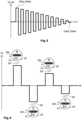
- Fig. 3 shows in particular the schematic course of the initialization alternating current IS over time t, as well as the schematic course of the initialization magnetic field IM generated by impressing the initialization alternating current IS into the sensor coil 26 at the location of the Wiegand wire 24. Since the magnetic field amplitude IMA of the initialization magnetic field IM is essentially directly proportional to the current amplitude ISA of the initialization alternating current IS, the course of the initialization alternating current IS and the initialization magnetic field IM in Fig. 3 for the sake of simplicity, it is represented by a single curve.
- the current direction of the initialization alternating current IS and the magnetization direction of the initialization magnetic field IM are each determined by the sign of the initialization alternating current IS and the initialization magnetic field IM.
- the initialization alternating current IS has a rectangular shape.
- the initialization alternating current IS can in principle have any alternating shape with a decreasing amplitude.
- the initialization alternating current IS can in particular also have a sawtooth or a sinusoidal shape.
- the initialization alternating current IS has a relatively large starting current amplitude ISAs at the beginning of the impression, so that the initialization magnetic field IM has a relatively large starting magnetic field amplitude IMAs.
- the current amplitude IMA of the initialization alternating current IS is continuously reduced over time t, such that the initialization alternating current IS has a relatively small final current amplitude ISAe at the end of the impression.
- the magnetic field amplitude IMA of the initialization magnetic field IM therefore decreases over time t to a relatively small final magnetic field amplitude IMAe.
- the starting current amplitude ISAs is at least twice as large as the final current amplitude ISAe, particularly preferably at least three times as large as the final current amplitude ISAe.
- the current direction of the initialization alternating current IS changes at least 10 times during the impressing, particularly preferably at least 20 times.
- the excitation unit 20 is rotated at a constant rotational frequency during the impression of the initialization alternating current IS and the excitation magnetic field EM is detected by means of the Wiegand sensor 22 and/or by means of an additional magnetic field sensor (not shown).
- the initialization unit 36 impresses an initialization alternating current pulse ISP into the sensor coil 26 each time an angle between the axial direction of the Wiegand wire and the excitation magnetic field is 80° to 100°, i.e. when the excitation magnetic field EM is essentially perpendicular to the axial direction of the Wiegand wire.
- the initialization alternating current pulses ISP have a current direction that alternates over time and a current amplitude ISA that decreases over time.
- Fig.4 shows a section of the course of the initialization alternating current IS and the orientation of the excitation unit 20 resulting from the rotation of the excitation unit 20 at the times of the initialization alternating current pulses ISP.
- the excitation unit 20 is activated at the beginning of the initialization of the Wiegand sensor-based angle measuring system 10 according to one of the two Fig. 5 schematically shown arrangements aligned with respect to the Wiegand sensor 22.
- the excitation unit 20 is thus arranged such that the excitation magnetic field EM is parallel to the axial direction of the Wiegand wire 24, i.e. the magnetic field lines of the excitation magnetic field EM run essentially parallel to the axial direction of the Wiegand wire 24.
- a starting current direction of the initialization alternating current IS at the beginning of the impression is always set such that a parallel component of the excitation magnetic field EM parallel to the axial direction of the Wiegand wire 24 and a parallel component of the initialization magnetic field IM parallel to the axial direction of the Wiegand wire 24 are rectified.
- the excitation unit 20 is rotated at a constant rotational frequency, wherein the rotational frequency of the excitation unit is half as large as an alternating frequency of the initialization alternating current IS, i.e. half as large as the frequency with which the current direction of the initialization alternating current changes.
- the parallel component of the excitation magnetic field EM and the parallel component of the initialization magnetic field IM are always rectified.
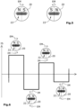
- Fig.6 shows a section of the course of the initialization alternating current IS and the orientation of the excitation unit 20 resulting from the rotation of the excitation unit 20 at the times of the extreme values of the initialization alternating current IS.
- the excitation unit 20 is controlled from one of the two Fig. 5
- the magnets are not rotated at a constant rotational frequency, but are always rotated alternately by 180° clockwise and 180° anti-clockwise.
- a rotational direction change frequency i.e. the frequency with which the rotational direction of the excitation unit is inverted, is exactly as large as the alternating frequency of the initialization alternating current IS, so that here too the parallel component of the excitation magnetic field EM and the parallel component of the initialization magnetic field IM are always in the same direction.
- the temporal course of the initialization alternating current IS and the alignment of the excitation unit 20 resulting from the "back and forth rotation" of the excitation unit 20 at the times of the extreme values of the initialization alternating current IS for the fourth embodiment are essentially identical to that in Fig.6 schematically shown course for the third embodiment.
- the excitation unit 20 is controlled from one of the two Fig. 5 schematically illustrated arrangements are always rotated alternately clockwise and counterclockwise with respect to the Wiegand sensor 22, wherein the rotation direction change frequency, as in the fourth embodiment, is exactly as large as the alternating frequency of the initialization alternating current IS.
- the excitation unit is not always rotated back and forth by a constant angle of rotation of 180°, but is rotated back and forth by a angle of rotation that decreases over time, so that the magnitude of the parallel component of the excitation magnetic field EM at the times of the extreme values of the initialization alternating current IS decreases over time.
Landscapes
- Physics & Mathematics (AREA)
- General Physics & Mathematics (AREA)
- Transmission And Conversion Of Sensor Element Output (AREA)
- Measurement Of Length, Angles, Or The Like Using Electric Or Magnetic Means (AREA)
Description
- Die vorliegende Erfindung betrifft ein Verfahren zur Initialisierung eines Wiegand-Sensor-basierten Drehwinkelmesssystems sowie ein Wiegand-Sensor-basiertes Drehwinkelmesssystem zur Erfassung einer Wellendrehbewegung, umfassend eine permanentmagnetische Erregereinheit, die mit einer zu erfassenden Welle mitdrehend montierbar ist, und einen feststehenden Wiegand-Sensor mit einem Wiegand-Draht und einer den Wiegand-Draht radial umschließenden Sensorspule.
- Wiegand-Sensor-basierte Drehwinkelmesssysteme sind aus dem Stand der Technik hinlänglich bekannt und werden insbesondere zur Steuerung und Überwachung von Elektromotoren, insbesondere Servomotoren, in Maschinen, Anlagen oder Fahrzeugen eingesetzt. Drehwinkelmesssysteme werden vielfach auch als Winkelmesseinrichtung, Drehwinkelsensor oder Drehgeber bezeichnet.
- Die permanentmagnetische Erregereinheit wird zu der Welle mitdrehend montiert und ist derart ausgebildet, dass bei einer Drehung der Erregereinheit am Ort des Wiegand-Sensors ein alternierendes Erregermagnetfeld erzeugt wird. Der Wiegand-Draht des Wiegand-Sensors ist magnetisch bistabil, wobei sich eine Magnetisierungsrichtung des Wiegand-Drahts unter Einwirkung eines der Magnetisierungsrichtung des Wiegand-Drahts entgegengerichteten, ausreichend starken Erregermagnetfelds schlagartig invertiert. Durch diese schlagartige Ummagnetisierung des Wiegand-Drahts wird in der den Wiegand-Draht radial umschließenden Sensorspule ein kurzer Spannungspuls generiert. Bei der Drehung der Erregereinheit werden durch das dabei erzeugte alternierende Erregermagnetfeld in der Sensorspule des Wiegand-Sensors folglich kontinuierlich Spannungspulse erzeugt, wobei die Frequenz der Spannungspulse direkt proportional zu einer Drehgeschwindigkeit der Erregereinheit und somit direkt proportional zu einer Drehgeschwindigkeit der Welle ist.
- Falls der Wiegand-Sensor beispielsweise beim Transport oder bei der Montage einem starken Magnetfeld ausgesetzt wird, kann der Wiegand-Draht derart stark aufmagnetisiert werden, dass im Betrieb des Drehwinkelmesssystems das von der Erregereinheit erzeugte Erregermagnetfeld nicht ausreicht, um den Wiegand-Draht vollständig umzumagnetisieren. Als Folge werden in der Sensorspule nur relativ schwache Spannungspulse erzeugt, die von einer Auswerteeinheit des Drehwinkelmesssystems nicht mehr zuverlässig erfasst werden können. Ferner kann es auf Grund der relativ schwachen Spannungspulse bei energieautarken Wiegand-Sensor-basierten Drehwinkelmesssystemen, in denen die elektrische Energie der Spannungspulse zur Energieversorgung des gesamten Drehwinkelmesssystems verwendet wird, zu Fehlfunktionen auf Grund einer unzureichenden Energieversorgung kommen.
- Die Patentschriften
GB2126351 GB2071336 DE102014116209 lehren jeweils einen Wiegand-Sensor, der einen Wieganddraht und eine diesen Draht radial umschließende Spule enthält. Unter bestimmten Umständen wird der Spule in allen drei Dokumenten ein Erregerstrom aufgeprägt. - Es stellt sich vor diesem Hintergrund die Aufgabe, ein zuverlässiges Wiegand-Sensor-basiertes Drehwinkelmesssystem zu schaffen.
- Diese Aufgabe wird durch ein Verfahren zur Initialisierung eines Wiegand-Sensor-basierten Drehwinkelmesssystems mit den Merkmalen des Anspruchs 1 sowie durch ein Wiegand-Sensor-basiertes Drehwinkelmesssystem mit den Merkmalen des Anspruchs 10 gelöst.
- Bei dem erfindungsgemäßen Verfahren zur Initialisierung eines Wiegand-Sensor-basierten Drehwinkelmesssystems wird das Drehwinkelmesssystem zuerst am Einsatzort montiert. Hierbei wird insbesondere eine permanentmagnetische Erregereinheit mitdrehend an einer zu erfassenden Welle montiert und wird ein Wiegand-Sensor mit einem Wiegand-Draht und einer den Wiegand-Draht radial umschließenden Sensorspule derart angeordnet, dass durch die Erregereinheit bei einer Rotation der Erregereinheit am Ort des Wiegand-Sensors ein alternierendes Erregermagnetfeld erzeugt wird. Die Erregereinheit wird bei der Montage typischerweise direkt an einem axialen Ende der Welle befestigt. Der Wiegand-Sensor ist typischerweise in einem Gehäuse angeordnet, dass bei der Montage auf das die Erregereinheit tragende axiale Ende der Welle aufgesetzt wird.
- Nach dem Montieren des Drehwinkelmesssystems am Einsatzort wird erfindungsgemäß von einer Initialisierungseinheit des Drehwinkelmesssystems ein Initialisierungswechselstrom in die den Wiegand-Draht radial umschließende Sensorspule eingeprägt, wobei der Initialisierungswechselstrom eine mit der Zeit alternierende Stromrichtung und eine mit der Zeit abfallende Stromamplitude aufweist. Hierdurch wird im Inneren der Spule, also am Ort des Wiegand-Drahts, ein parallel zu einer axialen Richtung des Wiegand-Drahts gerichtetes Initialisierungsmagnetfeld erzeugt, dessen Richtung mit der Zeit alterniert und dessen Amplitude/Stärke mit der Zeit abnimmt.
- Da der Wiegand-Draht ferromagnetisch ist, tendieren die sogenannten "Elementarmagnete" innerhalb des Wiegand-Drahts dazu, sich entlang eines extern eingeprägten Magnetfelds auszurichten. Durch das alternierende Initialisierungsmagnetfeld werden diese Elementarmagnete folglich kontinuierlich "umgeklappt", wobei der Anteil der bei einer Richtungsumkehr des Initialisierungsmagnetfelds jeweils umklappenden Elementarmagnete mit der abnehmenden Stärke des Initialisierungsmagnetfelds abnimmt. Hierdurch wird eine relativ ungeordnete Anordnung der Elementarmagnete innerhalb des Wiegand-Drahts erzeugt, sodass der Wiegand-Draht makroskopisch betrachtet im Wesentlichen keine magnetische Polarisierung aufweist, also nicht magnetisiert ist.
- Das erfindungsgemäße Verfahren zur Initialisierung eines Wiegand-Sensor-basierten Drehwinkelmesssystems ermöglicht somit eine durch den Transport oder die Montage des Drehwinkelmesssystems potentiell verursachte Aufmagnetisierung des Wiegand-Drahts idealerweise vollständig zu eliminieren oder zumindest signifikant zu reduzieren. Dies ermöglicht im Betrieb eine zuverlässige Ummagnetisierung des Wiegand-Drahts durch das von der permanentmagnetischen Erregereinheit erzeugte Erregermagnetfeld und somit eine zuverlässige Erfassung der Wellendrehbewegung. Das erfindungsgemäße Verfahren zur Initialisierung schafft folglich ein zuverlässiges Wiegand-Sensor-basiertes Drehwinkelmesssystem.
- Vorzugsweise wechselt die Stromrichtung des in die Sensorspule eingeprägten Initialisierungswechselstroms und somit die Richtung des hierdurch erzeugten Initialisierungsmagnetfelds mindestens 5-mal, vorzugsweise mindestens 10-mal, besonders bevorzugt mindestens 20-mal. Dies ermöglicht eine zuverlässige Reduktion der Aufmagnetisierung des Wiegand-Drahts.
- In einer bevorzugten Ausführung der vorliegenden Erfindung ist eine Startstromamplitude des Initialisierungswechselstroms zu Beginn des Einprägens des Initialisierungswechselstroms in die Sensorspule mindestens doppelt, vorzugsweise mindestens dreimal, so groß ist wie eine Endstromamplitude des Initialisierungswechselstroms am Ende des Einprägens des Initialisierungswechselstroms in die Sensorspule, um die Aufmagnetisierung des Wiegand-Drahts zuverlässig zu reduzieren. Vorteilhafterweise wird vor dem Einprägen des Initialisierungswechselstroms die permanentmagnetischen Erregereinheit des Drehwinkelmesssystems derart angeordnet, dass ein von der Erregereinheit am Ort des Wiegand-Drahts erzeugtes Erregermagnetfeld quer zu der axialen Richtung des Wiegand-Drahtes steht, also die Magnetfeldlinien des Erregermagnetfelds im Wesentlichen quer zu der axialen Richtung des Wiegand-Drahtes verlaufen. Vorzugsweise wird die Erregereinheit derart angeordnet, dass ein Winkel zwischen der axialen Richtung des Wiegand-Drahtes und dem Erregermagnetfeld 70° bis 110°, besonders bevorzugt 80° bis 100°, beträgt. Das Erregermagnetfeld weist folglich keine oder nur eine relativ geringe Erregermagnetfeldkomponente parallel zu der axialen Richtung des Wiegand-Drahtes auf, sodass das Erregermagnetfeld keinen signifikanten Einfluss auf die Ummagnetisierung des Wiegand-Drahts hat. Dies ermöglicht eine zuverlässige Ummagnetisierung des Wiegand-Drahts und somit eine zuverlässige Reduktion der Aufmagnetisierung des Wiegand-Drahts.
- In einer alternativen vorteilhaften Ausführung der vorliegenden Erfindung wird die Erregereinheit während des Einprägens des Initialisierungswechselstroms mit einer konstanten Umdrehungsfrequenz gedreht und wird der Initialisierungswechselstrom derart gepulst, dass Initialisierungswechselstrompulse dann in die Sensorspule eingeprägt werden, wenn ein von der Erregereinheit am Ort des Wiegand-Drahts erzeugtes Erregermagnetfeld quer zu einer axialen Richtung des Wiegand-Drahts steht. Vorzugsweise werden die Initialisierungswechselstrompulse jeweils zu einem Zeitpunkt in die Sensorspule eingeprägt, wenn ein Winkel zwischen der axialen Richtung des Wiegand-Drahtes und dem Erregermagnetfeld 70° bis 110°, besonders bevorzugt 80° bis 100°, beträgt. Dass Erregermagnetfeld kann hierbei mittels des Wiegand-Sensors oder mittels eines zusätzlichen Magnetfeldsensor erfasst werden. Wie zuvor beschrieben ermöglicht das Bestromen der Sensorspule zu einem Zeitpunkt, an dem das Erregermagnetfeld quer zu der axialen Richtung des Wiegand-Drahts steht, eine zuverlässige Ummagnetisierung des Wiegand-Drahts und somit eine zuverlässige Reduktion der Aufmagnetisierung des Wiegand-Drahts. Durch die gleichförmige Drehung der Erregereinheit und das gezielte Pulsen des Initialisierungswechselstroms ist hierfür keine exakte Positionierung der Erregereinheit erforderlich.
- In einer weiteren alternativen vorteilhaften Ausführung der vorliegenden Erfindung wird die permanentmagnetische Erregereinheit während des Einprägens des Initialisierungswechselstroms in die Sensorspule derart bewegt, dass eine zu der axialen Richtung des Wiegand-Drahts parallele Parallelkomponente des von der Erregereinheit am Ort des Wiegand-Drahts erzeugten Erregermagnetfelds und eine zu der axialen Richtung des Wiegand-Drahts parallele Parallelkomponente des durch das Einprägen des Initialisierungswechselstroms in die Sensorspule am Ort des Wiegand-Drahts erzeugten Initialisierungsmagnetfeld stets gleichgerichtet sind, also immer in die gleiche Richtung weisen. Die Begriffe "stets" und "immer" sind hierbei derart auszulegen, dass die Parallelkomponente des Erregermagnetfelds und die Parallelkomponente des Initialisierungsmagnetfelds während eines überwiegenden zeitlichen Anteils des Einprägens gleichgerichtet sind, sodass das Erregermagnetfeld das Initialisierungsmagnetfeld bei der Ummagnetisierung des Wiegand-Drahts "unterstützt". Dies ermöglicht eine zuverlässige Reduktion der Aufmagnetisierung des Wiegand-Drahts mit relativ geringen Stromamplituden und somit mit einer relativ geringen elektrischen Energie, ohne dass hierfür eine exakte Positionierung der Erregereinheit erforderlich ist.
- Vorzugsweise wird die Erregereinheit während des Einprägens des Initialisierungswechselstroms mit einer konstanten Umdrehungsfrequenz gedreht, wobei die Umdrehungsfrequenz der Erregereinheit direkt proportional zu einer Alternierungsfrequenz des Initialisierungswechselstroms ist. Der Proportionalitätsfaktor ist hierbei gleich dem Kehrwert der Anzahl der Magnetpole der Erregereinheit, sodass die Alternierungsfrequenz des am Ort des Wiegand-Sensors erzeugten Erregermagnetfelds gleich der Alternierungsfrequenz des durch das Einprägen des Initialisierungswechselstroms in die Sensorspule erzeugten Initialisierungsmagnetfelds ist. Dies stellt eine relativ einfach zu realisierende Möglichkeit dar, die Erregereinheit derart zu bewegen, dass die Parallelkomponente des Erregermagnetfelds und die Parallelkomponente des Initialisierungsmagnetfelds während des gesamten Einprägens des Initialisierungswechselstroms stets gleichgerichtet sind, da die Erregereinheit lediglich einmal vor dem Beginn des Einprägens des Initialisierungswechselstroms rotatorisch ausgerichtet werden muss.
- In einer alternativen bevorzugten Ausführung der vorliegenden Erfindung wird die Erregereinheit während des Einprägens des Initialisierungswechselstroms abwechselnd im Uhrzeigersinn und gegen den Uhrzeigersinn gedreht, derart, dass eine Drehrichtungswechselfrequenz der Erregereinheit direkt proportional zu einer Alternierungsfrequenz des Initialisierungswechselstroms ist. Dies ermöglich es, die Erregereinheit derart zu bewegen, dass die Parallelkomponente des Erregermagnetfelds und die Parallelkomponente des Initialisierungsmagnetfelds während des gesamten Einprägens des Initialisierungswechselstroms stets gleichgerichtet sind, ohne dass hierfür eine signifikante absolute Verdrehung der Erregereinheit und somit der Welle, an der die Erregereinheit befestigt, erforderlich ist.
- Besonders bevorzugt wird die Erregereinheit derart gedreht, dass ein Verdrehungswinkel, um den die Erregereinheit jeweils im Uhrzeigersinn beziehungsweise gegen den Uhrzeigersinn gedreht, mit der Zeit abnimmt. Hieraus ergibt sich, dass der Betrag der Parallelkomponente des Erregermagnetfelds zu den Zeitpunkten der Extremwerte des Initialisierungswechselstroms mit der Zeit abnimmt, wodurch die Aufmagnetisierung des Wiegand-Drahts besonders effizient reduziert werden kann.
- Das erfindungsgemäße Wiegand-Sensor-basierte Drehwinkelmesssystem zur Erfassung einer Wellendrehbewegung umfasst eine permanentmagnetische Erregereinheit, die mit einer zu erfassenden Welle mitdrehend montierbar ist. Die Erregereinheit kann durch einen einzigen permanentmagnetischen Körper gebildet sein, oder kann mehrere Permanentmagnete aufweisen, die an einem Magnetträger befestigt sind. Die Erregereinheit ist typischerweise rotationssymmetrisch und weist gleichmäßig entlang eines Umfangs der Erregereinheit verteilte Magnetpole auf. Die Erregereinheit ist typischerweise direkt an einem axialen Ende der Welle befestigt.
- Das erfindungsgemäße Wiegand-Sensor-basierte Drehwinkelmesssystem zur Erfassung einer Wellendrehbewegung umfasst einen feststehenden Wiegand-Sensor mit einem Wiegand-Draht und einer den Wiegand-Draht radial umschließenden Sensorspule. Der grundsätzliche Aufbau und die Funktionsweise des Wiegand-Sensors sind aus dem Stand der Technik hinlänglich bekannt. Der Wiegand-Sensor ist derart angeordnet, dass durch die Erregereinheit bei einer Rotation der Erregereinheit am Ort des Wiegand-Sensors ein alternierendes Erregermagnetfeld erzeugt wird. Der Wiegand-Sensor ist typischerweise in einem Gehäuse angeordnet, dass auf das die Erregereinheit tragende axiale Ende der Welle aufgesetzt ist.
- Erfindungsgemäß ist ferner eine Initialisierungseinheit vorhanden, die ausgebildet ist, einen Initialisierungswechselstrom in die Sensorspule einzuspeisen, wobei der Initialisierungswechselstrom eine mit der Zeit alternierende Stromrichtung und eine mit der Zeit abfallende Stromamplitude aufweist. Die Initialisierungseinheit ist somit ausgebildet ein am Ort des Wiegand-Drahts ein parallel zu einer axialen Richtung des Wiegand-Drahts gerichtetes Initialisierungsmagnetfeld zu erzeugen, dessen Richtung mit der Zeit alterniert und dessen Amplitude/Stärke mit der Zeit abnimmt. Die Initialisierungseinheit kann durch eine spezielle elektrische Schaltung und/oder durch einen entsprechend programmierten integrierten Schaltkreis oder Mikrocontroller gebildet sein. Die Initialisierungseinheit kann eine eigene Stromquelle umfassen, die elektrisch mit der Sensorspule verbunden ist, oder kann ausgebildet sein, eine separate, elektrisch mit der Sensorspule verbundene Stromquelle zu steuern.
- Die Initialisierungseinheit ermöglicht, wie zuvor beschrieben, eine Eliminierung oder zumindest eine signifikante Reduktion einer durch den Transport oder die Montage des Drehwinkelmesssystems potentiell verursachte Aufmagnetisierung des Wiegand-Drahts und schafft folglich ein zuverlässiges Wiegand-Sensor-basiertes Drehwinkelmesssystem.
- Vorzugsweise umfasst das erfindungsgemäße Wiegand-Sensor-basierte Drehwinkelmesssystem eine Auswerteeinheit mit einer Stromquelle, wobei die Auswerteeinheit ausgebildet ist, zur Erfassung einer Magnetisierungsrichtung des Wiegand-Drahts über die Stromquelle einen Erfassungsstrom in die Sensorspule einzuspeisen, wobei die Initialisierungseinheit ausgebildet ist, den Initialisierungswechselstrom über die Stromquelle der Auswerteeinheit in die Sensorspule einzuprägen. Die Auswerteeinheit kann durch eine spezielle elektrische Schaltung und/oder durch einen entsprechend programmierten integrierten Schaltkreis oder Mikrocontroller gebildet sein. Besonders bevorzugt sind die Auswerteeinheit und die Initialisierungseinheit durch einen einzigen integrierten Schaltkreis gebildet. Dies schafft ein kompaktes, einfach aufgebautes Wiegand-Sensor-basiertes Drehwinkelmesssystem.
- Ein Ausführungsbeispiel eines erfindungsgemäßen Wiegand-Sensor-basierten Drehwinkelmesssystems sowie verschiedene Ausführungsbeispiele eines erfindungsgemäßen Verfahrens zur Initialisierung des Wiegand-Sensor-basierten Drehwinkelmesssystems werden nachfolgend anhand der beigefügten Figuren beschrieben, wobei
-
Figur 1 eine schematische Darstellung eines erfindungsgemäßen Wiegand-Sensor-basierten Drehwinkelmesssystems zeigt, -
Figur 2 mögliche Initialisierungsstellungen einer Erregereinheit bezogen auf einen Wiegand-Sensor für ein erstes und ein zweites Ausführungsbeispiel des erfindungsgemäßen Initialisierungsverfahrens zur Initialisierung des Drehwinkelmesssystems ausFigur 1 zeigt, -
Figur 3 einen schematischen Verlauf eines in eine Sensorspule des Wiegand-Sensors des Drehwinkelmesssystems ausFigur 1 während eines erfindungsgemäßen Initialisierungsverfahrens eingeprägten Initialisierungswechselstroms und eines durch das Einprägen erzeugten Initialisierungsmagnetfelds zeigt, -
Figur 4 einen Ausschnitt eines schematischen Verlaufs eines während des zweiten Ausführungsbeispiels des erfindungsgemäßen Initialisierungsverfahrens in die Sensorspule eingeprägten Initialisierungswechselstroms sowie Stellungen der Erregereinheit bezogen auf den Wiegand-Sensor zu Zeitpunkten von Extremwerten des Initialisierungswechselstroms zeigt -
Figur 5 mögliche Startstellungen der Erregereinheit bezogen auf den Wiegand-Sensor für ein drittes, ein viertes und ein fünftes Ausführungsbeispiel des erfindungsgemäßen Initialisierungsverfahrens zeigt, und -
Figur 6 einen Ausschnitt eines schematischen Verlaufs eines während des dritten und des vierten Ausführungsbeispiels des erfindungsgemäßen Initialisierungsverfahrens in die Sensorspule eingeprägten Initialisierungswechselstroms sowie Stellungen der Erregereinheit bezogen auf den Wiegand-Sensor zu Zeitpunkten von Extremwerten des Initialisierungswechselstroms zeigt. -
Fig. 1 zeigt ein Wiegand-Sensor-basiertes Drehwinkelmesssystem 10, das an einem axialen Ende einer Welle 12 montiert ist. Das Drehwinkelmesssystem 10 umfasst ein Gehäuse 14 mit einem Gehäuseunterteil 16, das auf die Welle 12 aufgesetzt ist und die Welle radial umschließt, und einem Gehäusedeckel 18 der an dem Gehäuseunterteil 16 befestigt ist. - Das Wiegand-Sensor-basiertes Drehwinkelmesssystem 10 umfasst ferner eine permanentmagnetische Erregereinheit 20, die drehfest an einer Stirnfläche der Welle 12 befestigt ist und konzentrisch zu der Welle 12 positioniert ist. Die Erregereinheit 20 ist im vorliegenden Ausführungsbeispiel ein diametral magnetisierter Scheibenmagnet mit einem einzigen magnetischen Nordpol N und einem einzigen magnetischen Südpol S. Die Erregereinheit 20 erzeugt ein Erregermagnetfeld EM.
- Das Wiegand-Sensor-basiertes Drehwinkelmesssystem 10 umfasst ferner einen Wiegand-Sensor 22 mit einem Wiegand-Draht 24 und einer den Wiegand-Draht 24 radial umschließenden Sensorspule 26. Der Wiegand-Sensor 22 ist auf einer Leiterplatte 28 angeordnet, die axial beabstandet zu der Erregereinheit 20 in dem Gehäuse befestigt ist. Der Wiegand-Sensor 22 ist derart angeordnet, dass sich der Wiegand-Draht 24 senkrecht zu der axialen Richtung der Welle 12 erstreckt und konzentrisch zu der Erregereinheit positioniert ist.
- Das Wiegand-Sensor-basiertes Drehwinkelmesssystem 10 umfasst ferner einen integrierten Schaltkreis 30, der eine Auswerteeinheit 32 mit einer Stromquelle 34 und eine Initialisierungseinheit 36 bildet. Der integrierte Schaltkreis 30 ist auf der Leiterplatte 28 angeordnet und elektrisch mit dem Wiegand-Sensor 22 verbunden.
- Die Auswerteeinheit 32 ist ausgebildet, in der Sensorspule 26 generierte Spannungspulse auszuwerten. Die Auswerteeinheit 32 ist ferner ausgebildet zur Erfassung einer Magnetisierungsrichtung des Wiegand-Drahts 24 über die Stromquelle 34 einen Erfassungsstrom in die Sensorspule 26 einzuprägen.
- Die Initialisierungseinheit 36 ist ausgebildet, zur Erzeugung eines Initialisierungsmagnetfelds IM mit einer mit der Zeit alternierenden Magnetisierungsrichtung und einer mit der Zeit abfallenden Magnetfeldamplitude IMA, über die Stromquelle 34 der Auswerteeinheit 32 einen Initialisierungswechselstrom IS mit einer mit der Zeit alternierenden Stromrichtung und einer mit der Zeit abfallenden Stromamplitude ISA in die Sensorspule 26 einzuprägen.
- Nach der Montage an der Welle 12 wird mittels der Initialisierungseinheit 36 eine Initialisierung des Wiegand-Sensor-basierten Drehwinkelmesssystems 10 durchgeführt.
- In einem ersten Ausführungsbeispiel wird die Erregereinheit 20 zur Initialisierung des Wiegand-Sensor-basierten Drehwinkelmesssystems 10 gemäß einer der beiden in
Fig. 2 schematisch dargestellten Anordnungen bezogen auf den Wiegand-Sensor 22 ausgerichtet. Die Erregereinheit 20 wird also derart angeordnet, dass das Erregermagnetfeld EM senkrecht zu der axialen Richtung des Wiegand-Drahts 24 steht, also die Magnetfeldlinien des Erregermagnetfelds EM im Wesentlichen senkrecht zu der axialen Richtung des Wiegand-Drahts 24 verlaufen. - Anschließend wird durch die Initialisierungseinheit 36 der Initialisierungswechselstrom IS in die Sensorspule 26 eingeprägt, wobei der eingeprägte Initialisierungswechselstrom IS den in
Fig. 3 schematisch dargestellten zeitlichen Verlauf aufweist. Durch das Einprägen des Initialisierungswechselstroms IS in die Sensorspule 26 wird ein Initialisierungsmagnetfeld IM erzeugt, das parallel zur axialen Richtung des Wiegand-Drahts 24 steht, dessen Magnetfeldlinien also im Wesentlichen parallel zur axialen Richtung des Wiegand-Drahts 24 verlaufen. Die Richtung des Initialisierungsmagnetfelds IM wird durch die Stromrichtung des Initialisierungswechselstroms IS bestimmt. -
Fig. 3 zeigt im Speziellen den schematischen Verlauf des Initialisierungswechselstroms IS über der Zeit t, sowie den schematischen Verlauf des durch das Einprägen des Initialisierungswechselstroms IS in die Sensorspule 26 am Ort des Wiegand-Drahts 24 erzeugten Initialisierungsmagnetfelds IM. Da die Magnetfeldamplitude IMA des Initialisierungsmagnetfelds IM im Wesentlichen direkt proportional zur Stromamplitude ISA des Initialisierungswechselstroms IS ist, werden der Verlauf des Initialisierungswechselstroms IS und des Initialisierungsmagnetfelds IM inFig. 3 der Einfachheit halber durch eine einzige Kurve dargestellt. Die Stromrichtung des Initialisierungswechselstroms IS und die Magnetisierungsrichtung des Initialisierungsmagnetfelds IM ergeben sich jeweils aus dem Vorzeichen des Initialisierungswechselstroms IS und des Initialisierungsmagnetfelds IM. Der Einfachheit halber weist der Initialisierungswechselstrom IS einen rechteckförmigen Verlauf auf. Der Initialisierungswechselstrom IS kann jedoch grundsätzlich jeden beliebigen alternierenden Verlauf mit abfallender Amplitude aufweisen. Der Initialisierungswechselstrom IS kann insbesondere auch einen sägezahnförmigen oder einen sinusförmigen Verlauf aufweisen. - Der Initialisierungswechselstrom IS weist zu Beginn des Einprägens eine relativ große Startstromamplitude ISAs auf, sodass das Initialisierungsmagnetfeld IM eine relativ große Startmagnetfeldamplitude IMAs aufweist. Die Stromamplitude IMA des Initialisierungswechselstroms IS wird mit der Zeit t kontinuierlich reduziert, derart, dass der Initialisierungswechselstrom IS am Ende des Einprägens eine relativ kleine Endstromamplitude ISAe aufweist. Die Magnetfeldamplitude IMA des Initialisierungsmagnetfelds IM verringert sich folglich mit der Zeit t bis zu einer relativ kleinen Endmagnetfeldamplitude IMAe.
- Vorzugsweise ist die Startstromamplitude ISAs mindestens doppelt so groß wie die Endstromamplitude ISAe, besonders bevorzugt mindestens dreimal so groß wie Endstromamplitude ISAe. Vorzugsweise wechselt die Stromrichtung des Initialisierungswechselstrom IS während des Einprägens mindestens 10-mal, besonders bevorzugt mindestens 20-mal.
- In einem zweiten Ausführungsbeispiel wird die Erregereinheit 20 während des Einprägens des Initialisierungswechselstroms IS mit einer konstanten Umdrehungsfrequenz gedreht und wird das Erregermagnetfeld EM mittels des Wiegand-Sensors 22 und/oder mittels eines zusätzlichen Magnetfeldsensors (nicht dargestellt) erfasst. Durch die Initialisierungseinheit 36 wird jedes Mal dann ein Initialisierungswechselstrompuls ISP in die Sensorspule 26 eingeprägt, wenn ein Winkel zwischen der axialen Richtung des Wiegand-Drahtes und dem Erregermagnetfeld 80° bis 100° beträgt, also dann, wenn das Erregermagnetfeld EM im Wesentlichen quer zu der axialen Richtung des Wiegand-Drahts steht. Die Initialisierungswechselstrompulse ISP weisen hierbei eine mit der Zeit alternierende Stromrichtung und eine mit der Zeit abfallenden Stromamplitude ISA auf.
-
Fig.4 zeigt einen Ausschnitt des Verlaufs des Initialisierungswechselstroms IS und die sich durch die Drehung der Erregereinheit 20 zu den Zeitpunkten der Initialisierungswechselstrompulse ISP jeweils ergebende Ausrichtung der Erregereinheit 20. - In einem dritten Ausführungsbeispiel wird die Erregereinheit 20 zu Beginn der Initialisierung des Wiegand-Sensor-basierten Drehwinkelmesssystems 10 gemäß einer der beiden in
Fig. 5 schematisch dargestellt Anordnungen bezogen auf den Wiegand-Sensor 22 ausgerichtet. Die Erregereinheit 20 wird also derart angeordnet, dass das Erregermagnetfeld EM parallel zu der axialen Richtung des Wiegand-Drahts 24 steht, also die Magnetfeldlinien des Erregermagnetfelds EM im Wesentlichen parallel zu der axialen Richtung des Wiegand-Drahts 24 verlaufen. - Eine Startstromrichtung des Initialisierungswechselstroms IS zu Beginn des Einprägens ist hierbei immer derart eingestellt, dass eine zu der axialen Richtung des Wiegand-Drahts 24 parallele Parallelkomponente des Erregermagnetfelds EM und eine zu der axialen Richtung des Wiegand-Drahts 24 parallele Parallelkomponente des Initialisierungsmagnetfelds IM gleichgerichtet sind.
- Während des Einprägens des Initialisierungswechselstroms IS wird die Erregereinheit 20 mit einer konstanten Umdrehungsfrequenz gedreht, wobei die Umdrehungsfrequenz der Erregereinheit halb so groß ist wie eine Alternierungsfrequenz des Initialisierungswechselstroms IS, also halb so groß wie die Frequenz, mit der die Stromrichtung des Initialisierungswechselstroms wechselt. Dies führt dazu, dass die Parallelkomponente des Erregermagnetfelds EM und die Parallelkomponente des Initialisierungsmagnetfelds IM stets gleichgerichtet sind.
-
Fig.6 zeigt einen Ausschnitt des Verlaufs des Initialisierungswechselstroms IS und die sich durch die Drehung der Erregereinheit 20 zu den Zeitpunkten der Extremwerte des Initialisierungswechselstroms IS jeweils ergebende Ausrichtung der Erregereinheit 20. - In einem vierten Ausführungsbeispiel wird die Erregereinheit 20 ausgehend von einer der beiden in
Fig. 5 schematisch dargestellten Anordnungen bezogen auf den Wiegand-Sensor 22 nicht mit einer konstanten Umdrehungsfrequenz gedreht, sondern immer abwechselnd um 180° im Uhrzeigersinn und um 180° gegen den Uhrzeigersinn gedreht. Eine Drehrichtungswechselfrequenz, also die Frequenz, mit der die Drehrichtung der Erregereinheit invertiert wird, ist hierbei genau so groß wie die Alternierungsfrequenz des Initialisierungswechselstroms IS, sodass auch hier die Parallelkomponente des Erregermagnetfelds EM und die Parallelkomponente des Initialisierungsmagnetfelds IM stets gleichgerichtet sind. - Der zeitliche Verlauf des Initialisierungswechselstroms IS und die sich durch das "vor und zurück Drehen" der Erregereinheit 20 zu den Zeitpunkten der Extremwerte des Initialisierungswechselstroms IS jeweils ergebende Ausrichtung der Erregereinheit 20 für das vierte Ausführungsbeispiel sind im Wesentlichen identisch mit dem in
Fig.6 schematisch dargestellten Verlauf für das dritte Ausführungsbeispiel. - In einem fünften Ausführungsbeispiel wird die Erregereinheit 20 ausgehend von einer der beiden in
Fig. 5 schematisch dargestellten Anordnungen bezogen auf den Wiegand-Sensor 22 immer abwechselnd im Uhrzeigersinn und gegen den Uhrzeigersinn gedreht, wobei die Drehrichtungswechselfrequenz, wie im vierten Ausführungsbeispiel, genau so groß wie die Alternierungsfrequenz des Initialisierungswechselstroms IS ist. - Im Unterschied zum vierten Ausführungsbeispiel wird die Erregereinheit im fünften Ausführungsbeispiel jedoch nicht immer um einen konstanten Verdrehungswinkel von 180° vor und zurück gedreht, sondern um einen mit der Zeit abnehmenden Verdrehungswinkel vor und zurück gedreht, sodass der Betrag der Parallelkomponente des Erregermagnetfelds EM zu den Zeitpunkten der Extremwerte des Initialisierungswechselstroms IS mit der Zeit abnimmt.
-
- 10
- Wiegand-Sensor-basiertes Drehwinkelmesssystem
- 12
- Welle
- 14
- Gehäuse
- 16
- Gehäuseunterteil
- 18
- Gehäusedeckel
- 20
- Erregereinheit
- 22
- Wiegand-Sensor
- 24
- Wiegand-Draht
- 26
- Sensorspule
- 28
- Leiterplatte
- 30
- integrierter Schaltkreis
- 32
- Auswerteeinheit
- 34
- Stromquelle
- 36
- Initialisierungseinheit
- EM
- Erregermagnetfeld
- IM
- Initialisierungsmagnetfeld
- IMA
- Magnetfeldamplitude des Initialisierungsmagnetfelds
- IMAs
- Startmagnetfeldamplitude des Initialisierungsmagnetfelds
- IMAe
- Endmagnetfeldamplitude des Initialisierungsmagnetfelds
- IS
- Initialisierungswechselstrom
- ISA
- Stromamplitude des Initialisierungswechselstroms
- ISAs
- Startstromamplitude des Initialisierungswechselstroms
- ISAe
- Endstromamplitude des Initialisierungswechselstroms
- ISP
- Initialisierungswechselstrompulse
- N
- magnetischer Nordpol
- S
- magnetischer Südpol
Claims (12)
- Verfahren zur Initialisierung eines Wiegand-Sensor-basierten Drehwinkelmesssystems (10), umfassend die folgenden Verfahrensschritte:- Montieren des Drehwinkelmesssystems (10) am Einsatzort,- Einprägen eines Initialisierungswechselstroms (IS) in eine einen Wiegand-Draht (24) radial umschließende Sensorspule (26) nach dem Montieren, wobei das Verfahren dadurch charakterisiert ist, dass der Initialisierungswechselstrom (IS) eine mit der Zeit alternierende Stromrichtung und eine mit der Zeit abfallende Stromamplitude (ISA) aufweist.
- Verfahren zur Initialisierung eines Wiegand-Sensor-basierten Drehwinkelmesssystems (10) nach Anspruch 1, wobei die Stromrichtung des Initialisierungswechselstroms (IS) mindestens 5-mal, vorzugsweise mindestens 10-mal, besonders bevorzugt mindestens 20-mal wechselt.
- Verfahren zur Initialisierung eines Wiegand-Sensor-basierten Drehwinkelmesssystems (10) nach einem der vorhergehenden Ansprüche, wobei eine Startstromamplitude (ISAs) des Initialisierungswechselstroms (IS) zu Beginn des Einprägens mindestens doppelt, vorzugsweise mindestens dreimal, so groß ist wie eine Endstromamplitude (ISAe) des Initialisierungswechselstroms (IS) am Ende des Einprägens.
- Verfahren zur Initialisierung eines Wiegand-Sensor-basierten Drehwinkelmesssystems (10) nach einem der vorhergehenden Ansprüche, wobei vor dem Einprägen des Initialisierungswechselstroms (IS) der folgende Verfahrensschritt durchgeführt wird:- Anordnen einer permanentmagnetischen Erregereinheit (20) derart, dass ein von der Erregereinheit (20) am Ort des Wiegand-Drahts (24) erzeugtes Erregermagnetfeld (EM) quer zu einer axialen Richtung des Wiegand-Drahts (24) steht.
- Verfahren zur Initialisierung eines Wiegand-Sensor-basierten Drehwinkelmesssystems (10) nach einem der vorhergehenden Ansprüche, wobei die Erregereinheit (20) während des Einprägens des Initialisierungswechselstroms (IS) mit einer konstanten Umdrehungsfrequenz gedreht wird und wobei der Initialisierungswechselstrom (IS) derart gepulst wird, dass Initialisierungswechselstrompulse (ISP) dann in die Sensorspule eingeprägt (26) werden, wenn ein von der Erregereinheit (20) am Ort des Wiegand-Drahts (24) erzeugtes Erregermagnetfeld (EM) quer zu einer axialen Richtung des Wiegand-Drahts (24) steht.
- Verfahren zur Initialisierung eines Wiegand-Sensor-basierten Drehwinkelmesssystems (10) nach einem der Ansprüche 1 bis 3, umfassend den folgenden Verfahrensschritt:- Bewegen einer permanentmagnetischen Erregereinheit (20) während des Einprägens des Initialisierungswechselstroms (IS) derart, dass eine zu einer axialen Richtung des Wiegand-Drahts (24) parallele Parallelkomponente eines von der Erregereinheit (20) am Ort des Wiegand-Drahts (24) erzeugten Erregermagnetfelds (EM) und eine zu der axialen Richtung des Wiegand-Drahts (24) parallele Parallelkomponente eines durch das Einprägen des Initialisierungswechselstroms (IS) in die Sensorspule (26) am Ort des Wiegand-Drahts (24) erzeugten Initialisierungsmagnetfelds (IM) stets gleichgerichtet sind.
- Verfahren zur Initialisierung eines Wiegand-Sensor-basierten Drehwinkelmesssystems (10) nach Anspruch 6, wobei die Erregereinheit (20) während des Einprägens des Initialisierungswechselstroms (IS) mit einer konstanten Umdrehungsfrequenz gedreht wird, wobei die Umdrehungsfrequenz direkt proportional zu einer Alternierungsfrequenz des Initialisierungswechselstroms (IS) ist.
- Verfahren zur Initialisierung eines Wiegand-Sensor-basierten Drehwinkelmesssystems (10) nach Anspruch 6, wobei die Erregereinheit (20) während des Einprägens des Initialisierungswechselstroms (IS) abwechselnd im Uhrzeigersinn und gegen den Uhrzeigersinn gedreht wird, derart, dass eine Drehrichtungswechselfrequenz der Erregereinheit direkt proportional zu einer Alternierungsfrequenz des Initialisierungswechselstroms (IS) ist.
- Verfahren zur Initialisierung eines Wiegand-Sensor-basierten Drehwinkelmesssystems (10) nach Anspruch 8, wobei die Erregereinheit (20) derart gedreht wird, dass ein Verdrehungswinkel, um den die Erregereinheit (20) jeweils im Uhrzeigersinn beziehungsweise gegen den Uhrzeigersinn gedreht, mit der Zeit abnimmt.
- Wiegand-Sensor-basiertes Drehwinkelmesssystem (10) zur Erfassung einer Wellendrehbewegung, umfassend- eine permanentmagnetische Erregereinheit (20), die mit einer zu erfassenden Welle (12) mitdrehend montierbar ist, und- einen feststehenden Wiegand-Sensor (22) mitdadurch gekennzeichnet, dass• einem Wiegand-Draht (24) und• einer den Wiegand-Draht (24) radial umschließenden Sensorspule (26),
eine Initialisierungseinheit (36) vorhanden ist, die ausgebildet ist, einen Initialisierungswechselstrom (IS) in die Sensorspule (26) einzuspeisen, wobei der Initialisierungswechselstrom (IS) eine mit der Zeit alternierende Stromrichtung und eine mit der Zeit abfallende Stromamplitude (ISA) aufweist. - Wiegand-Sensor-basiertes Drehwinkelmesssystem (10) nach Anspruch 10, umfassend eine Auswerteeinheit (32) mit einer Stromquelle (34), wobei die Auswerteeinheit (32) ausgebildet ist, zur Erfassung einer Magnetisierungsrichtung des Wiegand-Drahts (24) über die Stromquelle (34) einen Erfassungsstrom in die Sensorspule (26) einzuspeisen, und wobei die Initialisierungseinheit (36) ausgebildet ist, den Initialisierungswechselstrom (IS) über die Stromquelle (34) der Auswerteeinheit (32) in die Sensorspule (26) einzuprägen.
- Wiegand-Sensor-basiertes Drehwinkelmesssystem (10) nach Anspruch 11, wobei die Auswerteeinheit (32) und die Initialisierungseinheit (36) durch einen einzigen integrierten Schaltkreis (30) gebildet sind.
Applications Claiming Priority (1)
| Application Number | Priority Date | Filing Date | Title |
|---|---|---|---|
| PCT/EP2021/052961 WO2022167099A1 (de) | 2021-02-08 | 2021-02-08 | Verfahren zur initialisierung eines drehwinkelmesssystems und drehwinkelmesssystem |
Publications (2)
| Publication Number | Publication Date |
|---|---|
| EP4288785A1 EP4288785A1 (de) | 2023-12-13 |
| EP4288785B1 true EP4288785B1 (de) | 2024-10-30 |
Family
ID=74874794
Family Applications (1)
| Application Number | Title | Priority Date | Filing Date |
|---|---|---|---|
| EP21712041.9A Active EP4288785B1 (de) | 2021-02-08 | 2021-02-08 | Verfahren zur initialisierung eines drehwinkelmesssystems und drehwinkelmesssystem |
Country Status (5)
| Country | Link |
|---|---|
| US (1) | US12571624B2 (de) |
| EP (1) | EP4288785B1 (de) |
| JP (1) | JP7659642B2 (de) |
| CN (1) | CN116964458A (de) |
| WO (1) | WO2022167099A1 (de) |
Family Cites Families (13)
| Publication number | Priority date | Publication date | Assignee | Title |
|---|---|---|---|---|
| DE3008581A1 (de) | 1980-03-06 | 1981-09-10 | Fa. Dr. Eugen Dürrwächter DODUCO, 7530 Pforzheim | Induktiver weggeber |
| DE3232306C1 (de) * | 1982-08-31 | 1983-11-17 | Doduco KG Dr. Eugen Dürrwächter, 7530 Pforzheim | Verfahren und Schaltungsanordnung zur magnetischen Erregung von Wiegand-Sensoren |
| DE4200082A1 (de) | 1992-01-03 | 1993-07-08 | Minnesota Mining & Mfg | Vorrichtung und verfahren zum erkennen eines magnetisierbaren markierungselementes |
| JPH06174472A (ja) * | 1992-12-10 | 1994-06-24 | Casio Comput Co Ltd | 電子式方位計 |
| JP2003075519A (ja) * | 2001-09-04 | 2003-03-12 | Shinkawa Denki Kk | 磁化反転素子 |
| JP2010249764A (ja) | 2009-04-20 | 2010-11-04 | Ntn Corp | バルクハウゼンノイズ検査装置 |
| DE102011011871A1 (de) * | 2011-01-06 | 2012-07-12 | Walter Mehnert | Verfahren und Vorrichtung zur Bestimmung der in einem Verbrauchs-Zeitintervall durch einen Durchflussmengenmesser strömenden Masse eines Fluids |
| DE102011002179B4 (de) * | 2011-04-19 | 2023-10-12 | Avago Technologies International Sales Pte. Limited | Verfahren und Anordnung zur Synchronisation eines Segmentzählers mit einem Feinpositionssensor |
| DE102012002204B4 (de) * | 2012-01-27 | 2019-06-13 | Avago Technologies International Sales Pte. Limited | Magnetfeldsensor |
| US9631948B2 (en) * | 2012-04-15 | 2017-04-25 | Avago Technologies General Ip (Singapore) Pte. Ltd. | Method and arrangement for synchronizing a segment counter with a fine position sensor |
| DE102014116209B4 (de) * | 2014-11-06 | 2025-03-20 | Ic - Haus Gmbh | Prüfschaltung zum Prüfen eines magnetischen Sensorelements |
| DE102016100499A1 (de) * | 2016-01-13 | 2017-07-13 | Fraba B.V. | Anordnung eines Drehwinkelmesssystems an einem Gehäuse |
| JP2021012174A (ja) * | 2019-07-09 | 2021-02-04 | パナソニックIpマネジメント株式会社 | 回転検出器及びそれを備えたモータ |
-
2021
- 2021-02-08 CN CN202180093143.XA patent/CN116964458A/zh active Pending
- 2021-02-08 US US18/276,044 patent/US12571624B2/en active Active
- 2021-02-08 JP JP2023547623A patent/JP7659642B2/ja active Active
- 2021-02-08 EP EP21712041.9A patent/EP4288785B1/de active Active
- 2021-02-08 WO PCT/EP2021/052961 patent/WO2022167099A1/de not_active Ceased
Also Published As
| Publication number | Publication date |
|---|---|
| EP4288785A1 (de) | 2023-12-13 |
| US12571624B2 (en) | 2026-03-10 |
| CN116964458A (zh) | 2023-10-27 |
| WO2022167099A1 (de) | 2022-08-11 |
| JP2024505702A (ja) | 2024-02-07 |
| JP7659642B2 (ja) | 2025-04-09 |
| US20240093981A1 (en) | 2024-03-21 |
Similar Documents
| Publication | Publication Date | Title |
|---|---|---|
| EP2515084B1 (de) | Verfahren für das Erfassen von Bewegungen eines Körpers mittels eines Segmentzählers und eines Feinpositionssensors | |
| EP0671008B1 (de) | Vorrichtung zur messung von drehbewegungen | |
| DE1197236B (de) | Anordnung zur beruehrungslosen Messung der axialen Verschiebung einer umlaufenden Welle gegen einen Festpunkt | |
| EP3555571B1 (de) | Sensorsystem zur bestimmung mindestens einer rotationseigenschaft eines um mindestens eine rotationsachse rotierenden elements | |
| DE102013203388B3 (de) | Rotorlagegeber für eine elektronisch kommutierte elektrische Maschine mit einem Referenzgeber | |
| DE102019115787B3 (de) | Verfahren zur Ermittlung des Winkels des Rotors eines Elektromotors, Steuergerät sowie Fahrzeug | |
| DE112013002617T5 (de) | Magnetdrehwinkeldetektor | |
| DE102016122547A1 (de) | Drehmomentregelvorrichtung, Elektroantrieb und Verfahren zur Drehmomentregelung | |
| DE102012104541A1 (de) | Verfahren und gerät zur stillstandsdetektion eines schrittmotors | |
| DE2643286C2 (de) | Einrichtung zur Lageerkennung einer rotierenden Welle | |
| DE102013217428A1 (de) | Elektrische Maschine, Rotorlagensensorik | |
| DE112018001301T5 (de) | Rotationssensor | |
| DE112017001450B4 (de) | Verfahren zum justierten Befestigen einer Magnetsensorvorrichtung an einem Aktuator | |
| EP4116688B1 (de) | Drehmomentmessung an einer scheibe | |
| DE102013225930A1 (de) | Verfahren zum Erfassen eines an einer Welle anliegenden Drehmoments | |
| DE102019211482A1 (de) | Sensoranordnung | |
| DE102016206773A1 (de) | Motorsteuerelektronik für einen bürstenlosen Gleichstrommotor | |
| EP1382935A1 (de) | Redundanter Drehwinkelsensor mit zwei magnetoresistiven Sensorelementen | |
| WO2022167099A1 (de) | Verfahren zur initialisierung eines drehwinkelmesssystems und drehwinkelmesssystem | |
| DE102004050586A1 (de) | Verfahren und Vorrichtung zur berührungslosen Drehwinkelerfassung | |
| WO2016202489A1 (de) | Drehzahlsensorvorrichtung, verfahren zum betreiben | |
| DE102018213246A1 (de) | Sensorsystem zur Bestimmung mindestens einer Rotationseigenschaft eines rotierenden Elements | |
| WO2013072219A2 (de) | Steuermodul für einen antriebsmotor | |
| DE19837331B4 (de) | Verfahren und Vorrichtung zum Messen einer Drehbewegung | |
| DE102017222847A1 (de) | Vorrichtung zum Auswerten eines Phasensignals einer elektrischen Maschine |
Legal Events
| Date | Code | Title | Description |
|---|---|---|---|
| STAA | Information on the status of an ep patent application or granted ep patent |
Free format text: STATUS: UNKNOWN |
|
| STAA | Information on the status of an ep patent application or granted ep patent |
Free format text: STATUS: THE INTERNATIONAL PUBLICATION HAS BEEN MADE |
|
| PUAI | Public reference made under article 153(3) epc to a published international application that has entered the european phase |
Free format text: ORIGINAL CODE: 0009012 |
|
| STAA | Information on the status of an ep patent application or granted ep patent |
Free format text: STATUS: REQUEST FOR EXAMINATION WAS MADE |
|
| 17P | Request for examination filed |
Effective date: 20230908 |
|
| AK | Designated contracting states |
Kind code of ref document: A1 Designated state(s): AL AT BE BG CH CY CZ DE DK EE ES FI FR GB GR HR HU IE IS IT LI LT LU LV MC MK MT NL NO PL PT RO RS SE SI SK SM TR |
|
| DAV | Request for validation of the european patent (deleted) | ||
| DAX | Request for extension of the european patent (deleted) | ||
| GRAP | Despatch of communication of intention to grant a patent |
Free format text: ORIGINAL CODE: EPIDOSNIGR1 |
|
| STAA | Information on the status of an ep patent application or granted ep patent |
Free format text: STATUS: GRANT OF PATENT IS INTENDED |
|
| INTG | Intention to grant announced |
Effective date: 20240618 |
|
| GRAS | Grant fee paid |
Free format text: ORIGINAL CODE: EPIDOSNIGR3 |
|
| GRAA | (expected) grant |
Free format text: ORIGINAL CODE: 0009210 |
|
| STAA | Information on the status of an ep patent application or granted ep patent |
Free format text: STATUS: THE PATENT HAS BEEN GRANTED |
|
| AK | Designated contracting states |
Kind code of ref document: B1 Designated state(s): AL AT BE BG CH CY CZ DE DK EE ES FI FR GB GR HR HU IE IS IT LI LT LU LV MC MK MT NL NO PL PT RO RS SE SI SK SM TR |
|
| REG | Reference to a national code |
Ref country code: GB Ref legal event code: FG4D Free format text: NOT ENGLISH |
|
| REG | Reference to a national code |
Ref country code: CH Ref legal event code: EP |
|
| REG | Reference to a national code |
Ref country code: IE Ref legal event code: FG4D Free format text: LANGUAGE OF EP DOCUMENT: GERMAN |
|
| REG | Reference to a national code |
Ref country code: DE Ref legal event code: R096 Ref document number: 502021005637 Country of ref document: DE |
|
| REG | Reference to a national code |
Ref country code: LT Ref legal event code: MG9D |
|
| REG | Reference to a national code |
Ref country code: DE Ref legal event code: R082 Ref document number: 502021005637 Country of ref document: DE Representative=s name: TERPATENT PARTGMBB, DE |
|
| REG | Reference to a national code |
Ref country code: NL Ref legal event code: MP Effective date: 20241030 |
|
| PG25 | Lapsed in a contracting state [announced via postgrant information from national office to epo] |
Ref country code: IS Free format text: LAPSE BECAUSE OF FAILURE TO SUBMIT A TRANSLATION OF THE DESCRIPTION OR TO PAY THE FEE WITHIN THE PRESCRIBED TIME-LIMIT Effective date: 20250228 Ref country code: PT Free format text: LAPSE BECAUSE OF FAILURE TO SUBMIT A TRANSLATION OF THE DESCRIPTION OR TO PAY THE FEE WITHIN THE PRESCRIBED TIME-LIMIT Effective date: 20250228 Ref country code: HR Free format text: LAPSE BECAUSE OF FAILURE TO SUBMIT A TRANSLATION OF THE DESCRIPTION OR TO PAY THE FEE WITHIN THE PRESCRIBED TIME-LIMIT Effective date: 20241030 |
|
| PG25 | Lapsed in a contracting state [announced via postgrant information from national office to epo] |
Ref country code: FI Free format text: LAPSE BECAUSE OF FAILURE TO SUBMIT A TRANSLATION OF THE DESCRIPTION OR TO PAY THE FEE WITHIN THE PRESCRIBED TIME-LIMIT Effective date: 20241030 Ref country code: NL Free format text: LAPSE BECAUSE OF FAILURE TO SUBMIT A TRANSLATION OF THE DESCRIPTION OR TO PAY THE FEE WITHIN THE PRESCRIBED TIME-LIMIT Effective date: 20241030 |
|
| PG25 | Lapsed in a contracting state [announced via postgrant information from national office to epo] |
Ref country code: BG Free format text: LAPSE BECAUSE OF FAILURE TO SUBMIT A TRANSLATION OF THE DESCRIPTION OR TO PAY THE FEE WITHIN THE PRESCRIBED TIME-LIMIT Effective date: 20241030 |
|
| PG25 | Lapsed in a contracting state [announced via postgrant information from national office to epo] |
Ref country code: ES Free format text: LAPSE BECAUSE OF FAILURE TO SUBMIT A TRANSLATION OF THE DESCRIPTION OR TO PAY THE FEE WITHIN THE PRESCRIBED TIME-LIMIT Effective date: 20241030 |
|
| PG25 | Lapsed in a contracting state [announced via postgrant information from national office to epo] |
Ref country code: NO Free format text: LAPSE BECAUSE OF FAILURE TO SUBMIT A TRANSLATION OF THE DESCRIPTION OR TO PAY THE FEE WITHIN THE PRESCRIBED TIME-LIMIT Effective date: 20250130 |
|
| PG25 | Lapsed in a contracting state [announced via postgrant information from national office to epo] |
Ref country code: LV Free format text: LAPSE BECAUSE OF FAILURE TO SUBMIT A TRANSLATION OF THE DESCRIPTION OR TO PAY THE FEE WITHIN THE PRESCRIBED TIME-LIMIT Effective date: 20241030 Ref country code: GR Free format text: LAPSE BECAUSE OF FAILURE TO SUBMIT A TRANSLATION OF THE DESCRIPTION OR TO PAY THE FEE WITHIN THE PRESCRIBED TIME-LIMIT Effective date: 20250131 |
|
| PGFP | Annual fee paid to national office [announced via postgrant information from national office to epo] |
Ref country code: AT Payment date: 20250417 Year of fee payment: 5 |
|
| PG25 | Lapsed in a contracting state [announced via postgrant information from national office to epo] |
Ref country code: PL Free format text: LAPSE BECAUSE OF FAILURE TO SUBMIT A TRANSLATION OF THE DESCRIPTION OR TO PAY THE FEE WITHIN THE PRESCRIBED TIME-LIMIT Effective date: 20241030 |
|
| PG25 | Lapsed in a contracting state [announced via postgrant information from national office to epo] |
Ref country code: RS Free format text: LAPSE BECAUSE OF FAILURE TO SUBMIT A TRANSLATION OF THE DESCRIPTION OR TO PAY THE FEE WITHIN THE PRESCRIBED TIME-LIMIT Effective date: 20250130 |
|
| PG25 | Lapsed in a contracting state [announced via postgrant information from national office to epo] |
Ref country code: SM Free format text: LAPSE BECAUSE OF FAILURE TO SUBMIT A TRANSLATION OF THE DESCRIPTION OR TO PAY THE FEE WITHIN THE PRESCRIBED TIME-LIMIT Effective date: 20241030 |
|
| PG25 | Lapsed in a contracting state [announced via postgrant information from national office to epo] |
Ref country code: DK Free format text: LAPSE BECAUSE OF FAILURE TO SUBMIT A TRANSLATION OF THE DESCRIPTION OR TO PAY THE FEE WITHIN THE PRESCRIBED TIME-LIMIT Effective date: 20241030 |
|
| PG25 | Lapsed in a contracting state [announced via postgrant information from national office to epo] |
Ref country code: EE Free format text: LAPSE BECAUSE OF FAILURE TO SUBMIT A TRANSLATION OF THE DESCRIPTION OR TO PAY THE FEE WITHIN THE PRESCRIBED TIME-LIMIT Effective date: 20241030 |
|
| PG25 | Lapsed in a contracting state [announced via postgrant information from national office to epo] |
Ref country code: RO Free format text: LAPSE BECAUSE OF FAILURE TO SUBMIT A TRANSLATION OF THE DESCRIPTION OR TO PAY THE FEE WITHIN THE PRESCRIBED TIME-LIMIT Effective date: 20241030 |
|
| PG25 | Lapsed in a contracting state [announced via postgrant information from national office to epo] |
Ref country code: SK Free format text: LAPSE BECAUSE OF FAILURE TO SUBMIT A TRANSLATION OF THE DESCRIPTION OR TO PAY THE FEE WITHIN THE PRESCRIBED TIME-LIMIT Effective date: 20241030 |
|
| PG25 | Lapsed in a contracting state [announced via postgrant information from national office to epo] |
Ref country code: CZ Free format text: LAPSE BECAUSE OF FAILURE TO SUBMIT A TRANSLATION OF THE DESCRIPTION OR TO PAY THE FEE WITHIN THE PRESCRIBED TIME-LIMIT Effective date: 20241030 |
|
| REG | Reference to a national code |
Ref country code: DE Ref legal event code: R097 Ref document number: 502021005637 Country of ref document: DE |
|
| PLBE | No opposition filed within time limit |
Free format text: ORIGINAL CODE: 0009261 |
|
| STAA | Information on the status of an ep patent application or granted ep patent |
Free format text: STATUS: NO OPPOSITION FILED WITHIN TIME LIMIT |
|
| PG25 | Lapsed in a contracting state [announced via postgrant information from national office to epo] |
Ref country code: SE Free format text: LAPSE BECAUSE OF FAILURE TO SUBMIT A TRANSLATION OF THE DESCRIPTION OR TO PAY THE FEE WITHIN THE PRESCRIBED TIME-LIMIT Effective date: 20241030 |
|
| PG25 | Lapsed in a contracting state [announced via postgrant information from national office to epo] |
Ref country code: MC Free format text: LAPSE BECAUSE OF FAILURE TO SUBMIT A TRANSLATION OF THE DESCRIPTION OR TO PAY THE FEE WITHIN THE PRESCRIBED TIME-LIMIT Effective date: 20241030 |
|
| REG | Reference to a national code |
Ref country code: CH Ref legal event code: PL |
|
| 26N | No opposition filed |
Effective date: 20250731 |
|
| PG25 | Lapsed in a contracting state [announced via postgrant information from national office to epo] |
Ref country code: LU Free format text: LAPSE BECAUSE OF NON-PAYMENT OF DUE FEES Effective date: 20250208 |
|
| PG25 | Lapsed in a contracting state [announced via postgrant information from national office to epo] |
Ref country code: CH Free format text: LAPSE BECAUSE OF NON-PAYMENT OF DUE FEES Effective date: 20250228 |
|
| REG | Reference to a national code |
Ref country code: BE Ref legal event code: MM Effective date: 20250228 |
|
| PG25 | Lapsed in a contracting state [announced via postgrant information from national office to epo] |
Ref country code: BE Free format text: LAPSE BECAUSE OF NON-PAYMENT OF DUE FEES Effective date: 20250228 |
|
| PG25 | Lapsed in a contracting state [announced via postgrant information from national office to epo] |
Ref country code: IE Free format text: LAPSE BECAUSE OF NON-PAYMENT OF DUE FEES Effective date: 20250208 |
|
| PGFP | Annual fee paid to national office [announced via postgrant information from national office to epo] |
Ref country code: GB Payment date: 20260219 Year of fee payment: 6 |
|
| PGFP | Annual fee paid to national office [announced via postgrant information from national office to epo] |
Ref country code: DE Payment date: 20260217 Year of fee payment: 6 |
|
| PGFP | Annual fee paid to national office [announced via postgrant information from national office to epo] |
Ref country code: IT Payment date: 20260227 Year of fee payment: 6 |
|
| PGFP | Annual fee paid to national office [announced via postgrant information from national office to epo] |
Ref country code: FR Payment date: 20260223 Year of fee payment: 6 |