EP4288716B1 - Methoden und systeme zur modulation des energieverbrauchs - Google Patents
Methoden und systeme zur modulation des energieverbrauchs Download PDFInfo
- Publication number
- EP4288716B1 EP4288716B1 EP22709380.4A EP22709380A EP4288716B1 EP 4288716 B1 EP4288716 B1 EP 4288716B1 EP 22709380 A EP22709380 A EP 22709380A EP 4288716 B1 EP4288716 B1 EP 4288716B1
- Authority
- EP
- European Patent Office
- Prior art keywords
- water
- temperature
- thermal energy
- time
- time threshold
- Prior art date
- Legal status (The legal status is an assumption and is not a legal conclusion. Google has not performed a legal analysis and makes no representation as to the accuracy of the status listed.)
- Active
Links
Images


Classifications
-
- F—MECHANICAL ENGINEERING; LIGHTING; HEATING; WEAPONS; BLASTING
- F24—HEATING; RANGES; VENTILATING
- F24D—DOMESTIC- OR SPACE-HEATING SYSTEMS, e.g. CENTRAL HEATING SYSTEMS; DOMESTIC HOT-WATER SUPPLY SYSTEMS; ELEMENTS OR COMPONENTS THEREFOR
- F24D17/00—Domestic hot-water supply systems
- F24D17/02—Domestic hot-water supply systems using heat pumps
-
- F—MECHANICAL ENGINEERING; LIGHTING; HEATING; WEAPONS; BLASTING
- F24—HEATING; RANGES; VENTILATING
- F24D—DOMESTIC- OR SPACE-HEATING SYSTEMS, e.g. CENTRAL HEATING SYSTEMS; DOMESTIC HOT-WATER SUPPLY SYSTEMS; ELEMENTS OR COMPONENTS THEREFOR
- F24D19/00—Details
- F24D19/10—Arrangement or mounting of control or safety devices
- F24D19/1006—Arrangement or mounting of control or safety devices for water heating systems
- F24D19/1051—Arrangement or mounting of control or safety devices for water heating systems for domestic hot water
- F24D19/1054—Arrangement or mounting of control or safety devices for water heating systems for domestic hot water the system uses a heat pump
-
- F—MECHANICAL ENGINEERING; LIGHTING; HEATING; WEAPONS; BLASTING
- F24—HEATING; RANGES; VENTILATING
- F24D—DOMESTIC- OR SPACE-HEATING SYSTEMS, e.g. CENTRAL HEATING SYSTEMS; DOMESTIC HOT-WATER SUPPLY SYSTEMS; ELEMENTS OR COMPONENTS THEREFOR
- F24D19/00—Details
- F24D19/10—Arrangement or mounting of control or safety devices
- F24D19/1006—Arrangement or mounting of control or safety devices for water heating systems
- F24D19/1051—Arrangement or mounting of control or safety devices for water heating systems for domestic hot water
- F24D19/1063—Arrangement or mounting of control or safety devices for water heating systems for domestic hot water counting of energy consumption
-
- F—MECHANICAL ENGINEERING; LIGHTING; HEATING; WEAPONS; BLASTING
- F24—HEATING; RANGES; VENTILATING
- F24H—FLUID HEATERS, e.g. WATER OR AIR HEATERS, HAVING HEAT-GENERATING MEANS, e.g. HEAT PUMPS, IN GENERAL
- F24H15/00—Control of fluid heaters
- F24H15/10—Control of fluid heaters characterised by the purpose of the control
- F24H15/144—Measuring or calculating energy consumption
-
- F—MECHANICAL ENGINEERING; LIGHTING; HEATING; WEAPONS; BLASTING
- F24—HEATING; RANGES; VENTILATING
- F24H—FLUID HEATERS, e.g. WATER OR AIR HEATERS, HAVING HEAT-GENERATING MEANS, e.g. HEAT PUMPS, IN GENERAL
- F24H15/00—Control of fluid heaters
- F24H15/10—Control of fluid heaters characterised by the purpose of the control
- F24H15/174—Supplying heated water with desired temperature or desired range of temperature
-
- F—MECHANICAL ENGINEERING; LIGHTING; HEATING; WEAPONS; BLASTING
- F24—HEATING; RANGES; VENTILATING
- F24H—FLUID HEATERS, e.g. WATER OR AIR HEATERS, HAVING HEAT-GENERATING MEANS, e.g. HEAT PUMPS, IN GENERAL
- F24H15/00—Control of fluid heaters
- F24H15/20—Control of fluid heaters characterised by control inputs
- F24H15/212—Temperature of the water
- F24H15/215—Temperature of the water before heating
-
- F—MECHANICAL ENGINEERING; LIGHTING; HEATING; WEAPONS; BLASTING
- F24—HEATING; RANGES; VENTILATING
- F24H—FLUID HEATERS, e.g. WATER OR AIR HEATERS, HAVING HEAT-GENERATING MEANS, e.g. HEAT PUMPS, IN GENERAL
- F24H15/00—Control of fluid heaters
- F24H15/20—Control of fluid heaters characterised by control inputs
- F24H15/212—Temperature of the water
- F24H15/219—Temperature of the water after heating
-
- F—MECHANICAL ENGINEERING; LIGHTING; HEATING; WEAPONS; BLASTING
- F24—HEATING; RANGES; VENTILATING
- F24H—FLUID HEATERS, e.g. WATER OR AIR HEATERS, HAVING HEAT-GENERATING MEANS, e.g. HEAT PUMPS, IN GENERAL
- F24H15/00—Control of fluid heaters
- F24H15/20—Control of fluid heaters characterised by control inputs
- F24H15/238—Flow rate
-
- F—MECHANICAL ENGINEERING; LIGHTING; HEATING; WEAPONS; BLASTING
- F24—HEATING; RANGES; VENTILATING
- F24H—FLUID HEATERS, e.g. WATER OR AIR HEATERS, HAVING HEAT-GENERATING MEANS, e.g. HEAT PUMPS, IN GENERAL
- F24H15/00—Control of fluid heaters
- F24H15/20—Control of fluid heaters characterised by control inputs
- F24H15/281—Input from user
-
- F—MECHANICAL ENGINEERING; LIGHTING; HEATING; WEAPONS; BLASTING
- F24—HEATING; RANGES; VENTILATING
- F24H—FLUID HEATERS, e.g. WATER OR AIR HEATERS, HAVING HEAT-GENERATING MEANS, e.g. HEAT PUMPS, IN GENERAL
- F24H15/00—Control of fluid heaters
- F24H15/40—Control of fluid heaters characterised by the type of controllers
- F24H15/414—Control of fluid heaters characterised by the type of controllers using electronic processing, e.g. computer-based
- F24H15/421—Control of fluid heaters characterised by the type of controllers using electronic processing, e.g. computer-based using pre-stored data
-
- F—MECHANICAL ENGINEERING; LIGHTING; HEATING; WEAPONS; BLASTING
- F24—HEATING; RANGES; VENTILATING
- F24H—FLUID HEATERS, e.g. WATER OR AIR HEATERS, HAVING HEAT-GENERATING MEANS, e.g. HEAT PUMPS, IN GENERAL
- F24H9/00—Details
- F24H9/20—Arrangement or mounting of control or safety devices
- F24H9/2007—Arrangement or mounting of control or safety devices for water heaters
-
- F—MECHANICAL ENGINEERING; LIGHTING; HEATING; WEAPONS; BLASTING
- F24—HEATING; RANGES; VENTILATING
- F24D—DOMESTIC- OR SPACE-HEATING SYSTEMS, e.g. CENTRAL HEATING SYSTEMS; DOMESTIC HOT-WATER SUPPLY SYSTEMS; ELEMENTS OR COMPONENTS THEREFOR
- F24D2200/00—Heat sources or energy sources
- F24D2200/12—Heat pump
-
- F—MECHANICAL ENGINEERING; LIGHTING; HEATING; WEAPONS; BLASTING
- F24—HEATING; RANGES; VENTILATING
- F24D—DOMESTIC- OR SPACE-HEATING SYSTEMS, e.g. CENTRAL HEATING SYSTEMS; DOMESTIC HOT-WATER SUPPLY SYSTEMS; ELEMENTS OR COMPONENTS THEREFOR
- F24D2220/00—Components of central heating installations excluding heat sources
- F24D2220/04—Sensors
- F24D2220/042—Temperature sensors
-
- F—MECHANICAL ENGINEERING; LIGHTING; HEATING; WEAPONS; BLASTING
- F24—HEATING; RANGES; VENTILATING
- F24D—DOMESTIC- OR SPACE-HEATING SYSTEMS, e.g. CENTRAL HEATING SYSTEMS; DOMESTIC HOT-WATER SUPPLY SYSTEMS; ELEMENTS OR COMPONENTS THEREFOR
- F24D2220/00—Components of central heating installations excluding heat sources
- F24D2220/08—Storage tanks
Definitions
- the present disclosure relates to methods and systems for managing utility consumption.
- the present disclosure relates to methods and systems for actively modulating energy consumption in a domestic setting, as well as commercial, public and other settings with water and/or energy provisions.
- heated water is required throughout the day all year round. It goes without saying that the provision of heated water requires both clean water and a source of heat.
- a heating system is provided to an often centralised water provision system to heat water up to a predetermined temperature e.g. set by a user, and the heat source used is conventionally one or more electric heating elements or burning of natural gas.
- the heat source used is conventionally one or more electric heating elements or burning of natural gas.
- utilities providers would implement a peak tariff which increases the unit cost of energy, partly to cover the additional cost of having to purchase more energy to supply to customers and partly to discourage unnecessary energy usage.
- a heat pump is a device that transfers thermal energy from a source of heat to a thermal reservoir.
- a heat pump requires electricity to accomplish the work of transferring thermal energy from the heat source to the thermal reservoir, it is generally more efficient than electrical resistance heaters (electrical heating elements) as it typically has a coefficient of performance of at least 3 or 4. This means under equal electricity usage 3 or 4 times the amount of heat can be provided to users via heat pumps compared to electrical resistance heaters.
- the heat transfer medium that carries the thermal energy is known as a refrigerant.
- Thermal energy from the air e.g. outside air, or air from a hot room in the house
- a ground source e.g. ground loop or water filled borehole
- the now higher energy refrigerant is compressed, causing it to raise temperature considerably, where this now hot refrigerant exchanges thermal energy via a heat exchanger to a heating water loop.
- heat extracted by the heat pump can be transferred to a water in an insulated tank that acts as a thermal energy storage, and the heated water may be used at a later time when needed.
- the heated water may be diverted to one or more water outlets, e.g. a tap, a shower, a radiator, as required.
- a heat pump generally requires more time compared to electrical resistance heaters to get water up to the desired temperature.
- CN 108 050 707 discloses a method for controlling a gas water heater with a cool bathing mode.
- the function of providing hot water at any temperature can be achieved, and the 'cool bathing mode' is added.
- the water outlet temperature is gradually changed along with the duration of bathing. After a water outlet temperature reaches a certain temperature, the temperature is kept for a period of time at first; and then the water temperature begins to drop, after the temperature is decreased to a certain temperature, the water temperature is kept unchanged.
- CN 111 981 700 discloses a water heater control method comprising obtaining an average cleaning time length, determining cooling start time and a cooling time length by using the average cleaning time length; when the cooling starting time is reached, respectively obtaining a current water outlet temperature and a target water outlet temperature which is less than the current water outlet temperature; and during the cooling time length, controlling the water outlet temperature of the water heater to fall from the current water outlet temperature to the target water outlet temperature.
- the invention provides a computer-implemented method of modulating energy consumption by a water provision system, the water provision system comprising a heat pump configured to transfer thermal energy from the surrounding to a thermal energy storage medium and a control module configured to control operation of the water provision system, the water provision system being configured to provide water heated by the thermal energy storage medium to a water outlet, the method being performed by the control module and comprising: upon determining that the water outlet is turned on, determining an elapse time from an initial time when the method is implemented; upon determining that the elapse time is less than a first time threshold, setting a temperature for heated water being provided to the water outlet to a first temperature, wherein the first time threshold is at least one day and the first temperature is higher than a target temperature; and progressively reducing the temperature for heated water being provided to the water outlet as the elapse time increases until the target temperature is reached.
- the temperature of the heated water being provided to the water outlet is set based on an elapse time since the present method is implemented, and the temperature of the heated water is progressively reduced over time until a target temperature is reached. In doing so, it is possible to gradually reduce the energy consumed by heating water for water outlets such as showers as well as potentially improving skin health for the user, based on studies showing that lower water temperature is beneficial to skin health.
- the present embodiment is of particular relevance when water is heated by a thermal energy storage, which stores heat transferred from the surrounding by a heat pump, in that by reducing the energy requirement for each use of heated water, it is possible for the same amount of energy that is stored in the thermal energy storage to last longer or to supply heated water to more water outlets.
- the water provision system can reduce its reliance on other less energy efficient means of heating water such as using electrical heating elements, thus making the water provision system more energy efficient overall.
- the method may further comprise, upon determining that the elapse time equals to or exceeds the first time threshold, setting a second temperature for heated water being provided to the water outlet, the second temperature being lower than the first temperature.
- the second temperature may be higher than the target temperature
- the method may further comprise, upon determining that the elapse time equals to or exceeds the first time threshold, determining if the elapse time exceeds a second time threshold.
- the method may further comprise, setting a third temperature for heated water being provided to the water outlet, the third temperature being lower than the second temperature.
- the third temperature may equal the target temperature
- the method may further comprise ceasing to reduce the temperature for heated water being provided to the water outlet.
- the control module ceases to reduce the water temperature any further such that water being provided to the water outlet will not become uncomfortably cold.
- the first time threshold may be one day, multiple days, one week, or multiple weeks.
- a time threshold for reducing the temperature of water being provided to the water outlet in the range of days or weeks users of the water outlet may have sufficient time to adapt to a new lower water temperature each time the water temperature is reduced, while still making significant changes to energy consumption.
- the second time threshold may be a multiple of the first time threshold.
- the second time threshold may be set to be the same as the first time threshold, longer than the first time threshold, or shorter than the first time threshold.
- the first time threshold may be predetermined by factory settings of the control module. In some embodiments, the first time threshold and/or the second time threshold may be set by a user.
- the target temperature may be set by a user.
- the target temperature may be predetermined by factory settings of the control module, for example based on energy consumption considerations and/or health considerations. In some embodiments, the target temperature may be determined based on an energy consumption target.
- the target temperature may be in a range of 38°C to 44°C.
- the first temperature may be set by a user at the initial time.
- the first temperature may be a water temperature that the user is accustomed to.
- the method may further comprise storing a plurality of user profiles, each profile corresponding to one of a plurality of users of the water outlet and comprises a corresponding first temperature.
- each profile may comprise a corresponding target temperature.
- each profile may comprise a corresponding first time threshold.
- the method may be performed by a machine learning algorithm.
- Another aspect of the present technology provides a control module for controlling operation of a water provision system, the water provision system comprising a heat pump configured to transfer thermal energy from the surrounding to a thermal energy storage medium and a control module configured to control operation of the water provision system, the water provision system being configured to provide water heated by the thermal energy storage medium to a water outlet, the control module being configured to implement the method described above.
- a further aspect of the present technology provides a water provision system for provisioning heated water to a water outlet, comprising: a thermal energy storage configured to store thermal energy; a heat exchanger arranged proximal to the thermal energy storage configured to heat water for provision by the water provision system using thermal energy stored in the thermal energy storage; a heat pump configured to transfer thermal energy from the surrounding to the thermal energy storage; and a control module configured to control operation of the water provision system, the control module being configured to: upon determining that the water outlet is turned on, determine an elapse time from an initial time when the method is implemented; upon determining that the elapse time is less than a first time threshold, set a temperature for heated water being provided to the water outlet to a first temperature, wherein the first time threshold is at least one day and the first temperature is higher than a target temperature; and progressively reduce the temperature for heated water being provided to the water outlet as the elapse time increases until a target temperature is reached.
- the water provision system may further comprise one or more electrical heating elements configured to heat water for provision by the water provision system.
- the water outlet is a shower.
- a yet further aspect of the present technology provides a computer program stored on a computer readable storage medium for, when executed on a computer system, instructing the computer system to carry out the method as described above.
- the present disclosure provides various approaches for the provision of heated water using or assisted by a heat pump, and in some cases for modulating the use of utilities including water and energy to reduce water and energy wastage.
- cold and heated water is provisioned by a centralized water provision system to a plurality of water outlets, including taps, showers, radiators, etc., for a building in a domestic or commercial setting.
- An exemplary water provision system 100 is shown in Fig. 1 .
- the water provision system 100 comprises a control module 110.
- the control module 110 is communicatively coupled to, and configured to control, various elements of the water provision system, including flow control 130 for example in the form of one or more valves arranged to control the flow of water internal and external to the system, a (ground source or air source) heat pump 140 configured to extract heat from the surrounding and deposit the extracted heat in a thermal energy storage 150 to be used to heat water, and one or more electric heating elements 160 configured to directly heat cold water to a desired temperature by controlling the amount of energy supplied to the electric heating elements 160. Heated water, whether heated by the thermal energy storage 150 or heated by the electric heating elements 160, is then directed to one or more water outlets and or a central heating system as and when needed.
- flow control 130 for example in the form of one or more valves arranged to control the flow of water internal and external to the system
- a (ground source or air source) heat pump 140 configured to extract heat from the surrounding and deposit the extracted heat in a thermal energy storage 150 to be used to heat water
- the heat pump 140 extracts heat from the surrounding into a thermal energy storage medium within the thermal energy storage 150 until the thermal energy storage medium reach an operation temperature, then cold water e.g. from the mains can be heated by the thermal energy storage medium to the desired temperature. The heated water may then be supplied to various water outlets in the system.
- the control module 110 is configured to receive input from a plurality of sensors 170-1, 170-2, 170-3, ..., 170-n.
- the plurality of sensors 170-1, 170-2, 170-3, ..., 170-n may for example include one or more air temperature sensors disposed indoor and/or outdoor, one or more water temperature sensors, one or more water pressure sensors, one or more timers, one or more motion sensors, and may include other sensors not directly linked to the water provision system 100 such as a GPS signal receiver, calendar, weather forecasting app on e.g. a smartphone carried by an occupant and in communication with the control module via a communication channel.
- the control module 110 is configured, in the present embodiment, to use the received input to perform a variety of control functions, for example controlling the flow of water through the flow control 130 to the thermal energy storage 150 or electric heating elements 160 to heat water.
- one or more machine learning algorithm (MLA) 120 may execute on the control module 110, for example on a processor (not shown) of the control module 110 or on a server remote from the control module 110 and communicates with the processor of the control module 110 over a communication channel.
- the MLA 120 may be trained using the input sensor data received by the control module 110 to establish a baseline water and energy usage pattern based e.g. on the time of the day, the day of the week, the date (e.g. seasonal changes, public holiday), occupancy, etc.
- the learned usage pattern may then be used to determine, and in some cases improve, the various control functions performed by the control module 110, and/or generate a report e.g. to enable a user to analyze their utility usage and/or provide suggestions for more efficient utility usage.
- the heat pump 140 may for example use a phase change material (PCM), which changes from a solid to a liquid upon heating, as a thermal energy storage medium.
- PCM phase change material
- additional time may be required to turn the PCM from solid to liquid, if it has been allowed to solidify, before thermal energy extracted by the heat pump can be used to raise the temperature of the thermal storage medium.
- a phase change material may be used as a thermal storage medium for the heat pump.
- phase change materials are paraffin waxes which have a solid-liquid phase change at temperatures of interest for domestic hot water supplies and for use in combination with heat pumps.
- paraffin waxes that melt at temperatures in the range 40 to 60 degrees Celsius (°C), and within this range waxes can be found that melt at different temperatures to suit specific applications.
- Typical latent heat capacity is between about 180kJ/kg and 230kJ/kg and a specific heat capacity of perhaps 2.27Jg -1 K -1 in the liquid phase, and 2.1Jg -1 K -1 in the solid phase. It can be seen that very considerable amounts of energy can be stored taking using the latent heat of fusion.
- More energy can also be stored by heating the phase change liquid above its melting point.
- the heat pump may be operated to "charge” the thermal energy storage to a higher-than-normal temperature to "overheat" the thermal energy storage.
- a suitable choice of wax may be one with a melting point at around 48°C, such as n-tricosane C 23 , or paraffin C 20 -C 33 , which requires the heat pump to operate at a temperature of around 51°C, and is capable of heating water to a satisfactory temperature of around 45°C for general domestic hot water, sufficient for e.g. kitchen/bathroom taps, shower, etc.
- Cold water may be added to a flow to reduce water temperature if desired.
- the maximum difference between the input and output temperature of the fluid heated by the heat pump is preferably kept in the range of 5°C to 7°C, although it can be as high as 10°C.
- salt hydrates are also suitable for latent heat energy storage systems such as the present ones.
- Salt hydrates in this context are mixtures of inorganic salts and water, with the phase change involving the loss of all or much of their water. At the phase transition, the hydrate crystals are divided into anhydrous (or less aqueous) salt and water.
- Advantages of salt hydrates are that they have much higher thermal conductivities than paraffin waxes (between 2 to 5 times higher), and a much smaller volume change with phase transition.
- a suitable salt hydrate for the current application is Na 2 S 2 O 3 ⁇ 5H 2 O, which has a melting point around 48°C to 49°C, and latent heat of 200-220 kJ/kg.
- the optimal water temperature for shower or bath water for skin health is no more than a few degrees above body temperature, that is between about 37°C to 41°C.
- a few degrees above body temperature that is between about 37°C to 41°C.
- the present invention therefore provides methods and systems to modulate the water temperature of shower and bath water, and in turn modulate energy consumption.
- the invention recognizes that, for most users, a sudden change in shower or bath water temperature, especially when accustomed to a much higher water temperature, would result in much discomfort that may result in a reduced likelihood of the users adapting to the new water temperature.
- the shower water temperature is gradually reduced from a user's preferred water temperature to a selected optimal water temperature (e.g. 41°C).
- a selected optimal water temperature e.g. 41°C.
- This approach can be implemented to modulate bath water temperature if desired
- a second embodiment which is not part of the invention, shows that the shower water temperature is alternately modulated between a higher water temperature and a lower water temperature (e.g. between 37°C and 41°C) during a single shower.
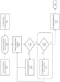
- Fig. 2 shows a computer-implemented method of modulating shower water temperature according to the invention.
- heated water is supplied to a shower by the water provision system 100 described above.
- the control module 110 is configured to implement a gradual temperature reduction program 200 to gradually reduce shower water temperature over a period of time to a target temperature.
- the control module 110 is provided with a timer (not shown).
- a user preferred water temperature T1 is input at S201 to the program 200
- a target water temperature T3 is input at S202 to the program 200.
- the user preferred water temperature T1 represents the temperature at which the user normally sets the shower water before the program 200 is implemented, and may for example be 45°C.
- the target water temperature T3 represents the shower water temperature that the user wishes to adapt to, e.g. 38°C, or an optimal water temperature predetermined by factory setting, e.g. 41°C, based for example on an energy consumption target and/or on health benefit considerations.
- the control module 110 initiates the timer to record an elapse time from when the program 200 is first implemented (initial time). Then, upon detecting that the shower is turned on at S203, the control module 110 determines at S204 if the elapse time t recorded by the timer since the program 200 is implemented has exceeded a predetermined first time threshold t1 for reducing water temperature.
- the first time threshold t1 may be predetermined by factory setting or may be set by the user, and may for example be one day, multiple days, one week, etc.
- the control module 110 sets the shower water temperature to a first temperature T1, the user preferred water temperature, at S205. The method then returns to S203 at the end of the shower until the next time the control module 110 detects the shower is turned on again.
- the control module 110 determines at S206 if the elapse time t has exceeded a predetermined second time threshold t2.
- the second time threshold t2 may again be predetermined by factory setting or may be set by the user, and may for example be multiple of the first time threshold t1 (e.g. t1 may be one week then t2 may be two weeks), or the second time threshold t2 may be set independently of the first time threshold t1 (e.g. t1 may be one week and t2 may be twenty days).
- the control module 110 sets the shower water temperature to a second temperature T2 at S207.
- the second temperature T2 is a temperature lower than the first temperature T1 but higher than the optimal temperature T3, and may be set by the user or calculated based on the user preferred temperature T1 and the target temperature T3, for example T2 may be a temperature halfway between T1 and T3 (e.g. if T1 is 45°C and T3 is 41°C, T2 may be 43°C).
- the method then returns to S203 at the end of the shower until the next time the control module 110 detects the shower is turned on again.
- control module 110 sets the shower water temperature to a third temperature T3, the target water temperature, at S208.
- Fig. 2 shows one intermediate water temperature T2 for simplicity. It will however be apparent to one skilled in the art that more than one intermediate stages with multiple intermediate water temperatures at corresponding intermediate time thresholds are possible and may sometimes be desirable, for example when there is a big difference between the user preferred temperature T1 and the final optimal temperature T3.
- T1 45°C
- T3 41°C
- the control module 110 implementing the program 200 may set the shower water temperature to 44°C after one week, then 43°C after two weeks, 42°C after three weeks, and finally 41°C after four weeks.
- the intermediate step can be omitted altogether.
- the present embodiment it is possible to gradually reduce the energy consumed by heating water for showers as well as potentially improving skin health for the user.
- the present embodiment is of particular relevance when shower water is heated by the thermal energy storage 150, which stores heat transferred from the surrounding by the heat pump 140, in that by reducing the energy requirement for showers, energy stored in the thermal energy storage 150 may be diverted for other uses such as supplying heated water to kitchen and bathroom taps. In doing so, the water provision system 100 may rely less on the less energy efficient electrical heating elements 160, making the water provision system 100 more energy efficient overall.
- Fig. 3 shows a method of modulating shower water temperature which is not part of the claimed invention.
- heated water is supplied to a shower by the water provision system 100 described above.
- the control module 110 is configured to implement an alternating temperature modulation program 300 to modulate shower water temperature by alternating between a higher water temperature and a lower water temperature during a shower (this is most likely switching back and forth multiple times but could possibly be one change during a single shower).
- the control module 110 is provided with a timer (not shown).
- a maximum water temperature T4 is input at S301 to the program 300
- a minimum water temperature T5 is input at S302 to the program 300.
- the maximum water temperature T4 and the minimum water temperature T5 are the water temperatures between which the control module 110 will alternate during a shower, e.g. 41°C and 38°C respectively, and they may be set by the user manually or predetermined by factory setting e.g. based on energy consumption considerations and/or health benefit considerations.
- the control module 110 sets the water temperature of the shower to the maximum water temperature T4 at S304 and sets the time t on the timer to 0.
- the control module 110 then continually monitors the timer and determines, at S305, whether the time t has reached a fourth time threshold t4. If the time t has not reached the fourth time threshold t4, the control module 110 maintains the shower water temperature at T4 and continues to monitor the timer.
- control module 110 determines that the time t has reached the fourth time threshold t4
- the control module 110 then controls the water provision system 100 to change the shower water temperature from the maximum water temperature T4 to the minimum water temperature T5 at S306, e.g. by reducing the proportion of heated water in the water supplied to the shower.
- the control module 110 resets the time t on the timer to 0.
- the control module 110 again continually monitors the timer and determines, at S307, whether the time t has reached a fifth time threshold t5. If the time t has not reached the fifth time threshold t5, the control module 110 maintains the shower water temperature at T5 and continues to monitor the timer.
- control module 110 determines that the time t has reached the fifth time threshold t5
- the control module 110 controls the water provision system 100 to return the shower water temperature from the minimum water temperature T5 to the maximum water temperature T4 again at S304, e.g. by returning the proportion of heated water in the water supplied to the shower to the initial level.
- the control module 110 resets the time t on the timer to 0 and continually monitors the timer.
- the control module 110 modulates shower water temperature by periodically alternating the shower water temperature between the maximum water temperature T4 and the minimum water temperature T5 during a single shower.
- the frequency at which the water temperature change occurs i.e. t4 and t5 may be manually set by the user or predetermined by factory setting.
- t4 and t5 may be the same, e.g. one minute, or t4 and t5 may be different, e.g. t4 equals five minutes and t5 equals one minute such that the shower is at the warmer setting for five minutes then change to the cooler setting for one minute.
- a further method of modulation could be 1 minute T4, 1 minute T5, 1 minute T4, one minute T5. Producing a sinusoidal type temperature curve, where the average temperature would then be lower than T4.
- the control module 110 may first set the shower water temperature to the minimum water temperature T5 when the shower is initially turned on. After the fourth time threshold t4, the control module 110 may alternate the shower water temperature to the maximum water temperature T4, then after the fifth time threshold t5 alternate the shower water temperature back to the minimum water temperature T5 and thereafter alternating back and forth between water temperatures T4 and T5 until the shower is turned off.
- the control module 110 may first set the shower water temperature to the maximum water temperature T4 (or the minimum water temperature T5), then after a period of time alternate the shower water temperature to the minimum water temperature T5 (or the maximum water temperature T4) and maintain the shower water temperature at T5 (or T4) until the shower is turned off.
- Embodiments disclosed herein may be implemented using one or more machine learning algorithms such as the MLA 120 of the control module 110.
- the MLA 120 may establish the preferred shower water temperature of a user, and moreover may establish a variation in shower water temperature that is acceptable to the user, e.g. based on any variation in shower water temperature set by the user over a period of time.
- the MLA 120 may then be deployed to set a progressively lower shower water temperature for the user over a period of time based on the starting water temperature, an optimal water temperature, and the established acceptable variation.
- the MLA 120 may for example set a maximum shower water temperature and a minimum shower water temperature based on the user's preferred water temperature, and alternate during a single shower based on the acceptable variation.
- the programs 200 and/or 300 may be implemented differently for each of a plurality of users.
- the control module 110 may be configured to enable multiple user profiles such that each user may set different preferences for the temperatures T1, T2, T3, T4 and/or T5, and different time thresholds t1, t2, t4 and/or t5.
- the present techniques may be embodied as a system, method or computer program product. Accordingly, the present techniques may take the form of an entirely hardware embodiment, an entirely software embodiment, or an embodiment combining software and hardware.
- the present techniques may take the form of a computer program product embodied in a computer readable medium having computer readable program code embodied thereon.
- the computer readable medium may be a computer readable signal medium or a computer readable storage medium.
- a computer readable medium may be, for example, but is not limited to, an electronic, magnetic, optical, electromagnetic, infrared, or semiconductor system, apparatus, or device, or any suitable combination of the foregoing.
- Computer program code for carrying out operations of the present techniques may be written in any combination of one or more programming languages, including object-oriented programming languages and conventional procedural programming languages.
- program code for carrying out operations of the present techniques may comprise source, object or executable code in a conventional programming language (interpreted or compiled) such as C, or assembly code, code for setting up or controlling an ASIC (Application Specific Integrated Circuit) or FPGA (Field Programmable Gate Array), or code for a hardware description language such as VerilogTM or VHDL (Very high-speed integrated circuit Hardware Description Language).
- a conventional programming language interpreted or compiled
- ASIC Application Specific Integrated Circuit
- FPGA Field Programmable Gate Array
- VerilogTM or VHDL Very high-speed integrated circuit Hardware Description Language
- the program code may execute entirely on the user's computer, partly on the user's computer and partly on a remote computer or entirely on the remote computer or server.
- the remote computer may be connected to the user's computer through any type of network.
- Code components may be embodied as procedures, methods or the like, and may comprise sub-components which may take the form of instructions or sequences of instructions at any of the levels of abstraction, from the direct machine instructions of a native instruction set to high-level compiled or interpreted language constructs.
- a logical method may suitably be embodied in a logic apparatus comprising logic elements to perform the steps of the method, and that such logic elements may comprise components such as logic gates in, for example a programmable logic array or application-specific integrated circuit.
- Such a logic arrangement may further be embodied in enabling elements for temporarily or permanently establishing logic structures in such an array or circuit using, for example, a virtual hardware descriptor language, which may be stored and transmitted using fixed or transmittable carrier media.
- processor any functional block labeled as a "processor”
- functions of the various elements shown in the figures may be provided through the use of dedicated hardware as well as hardware capable of executing software in association with appropriate software.
- the functions may be provided by a single dedicated processor, by a single shared processor, or by a plurality of individual processors, some of which may be shared.
- processor or “controller” should not be construed to refer exclusively to hardware capable of executing software, and may implicitly include, without limitation, digital signal processor (DSP) hardware, network processor, application specific integrated circuit (ASIC), field programmable gate array (FPGA), read-only memory (ROM) for storing software, random access memory (RAM), and non-volatile storage.
- DSP digital signal processor
- ASIC application specific integrated circuit
- FPGA field programmable gate array
- ROM read-only memory
- RAM random access memory
- non-volatile storage Other hardware, conventional and/or custom, may also be included.
Landscapes
- Engineering & Computer Science (AREA)
- Physics & Mathematics (AREA)
- Thermal Sciences (AREA)
- Chemical & Material Sciences (AREA)
- Combustion & Propulsion (AREA)
- Mechanical Engineering (AREA)
- General Engineering & Computer Science (AREA)
- Computer Hardware Design (AREA)
- Fluid Mechanics (AREA)
- Heat-Pump Type And Storage Water Heaters (AREA)
- Oscillators With Electromechanical Resonators (AREA)
Claims (15)
- Computerimplementiertes Verfahren zur Modulation des Energieverbrauchs durch ein Wasserversorgungssystem (100), wobei das Wasserversorgungssystem (100) eine Wärmepumpe (140), die so konfiguriert ist, dass sie Wärmeenergie aus der Umgebung auf ein Wärmeenergiespeichermedium (150) überträgt, und ein Steuermodul (110) umfasst, das so konfiguriert ist, dass es den Betrieb des Wasserversorgungssystem (100) steuert, wobei das Wasserversorgungssystem (100) so konfiguriert ist, dass es durch das Wärmeenergiespeichermedium (150) erwärmtes Wasser an einen Wasserauslass liefert, wobei das Verfahren durch das Steuermodul (110) durchgeführt wird und umfasst:nach dem Bestimmen (S203), dass der Wasserauslass eingeschaltet ist, Bestimmen (S204) einer Zeitspanne (t) ab einem Anfangszeitpunkt, zu dem das Verfahren implementiert wird;bei der Bestimmung, dass die Zeitspanne (t) kleiner als ein erster Zeitschwellenwert (ti) ist, Einstellen (S205) einer Temperatur für erwärmtes Wasser, das dem Wasserauslass bereitgestellt wird, auf eine erste Temperatur (Ti),wobei der erste Zeitschwellenwert (ti) mindestens einen Tag beträgt und die erste Temperatur (Ti) höher als eine Zieltemperatur ist; undschrittweises Reduzieren der Temperatur für erwärmtes Wasser, das dem Wasserauslass bereitgestellt wird, während die Zeitspanne zunimmt, bis die Zieltemperatur erreicht ist.
- Verfahren nach Anspruch 1, das ferner, bei der Bestimmung, dass die Zeitspanne (t) gleich oder größer als der erste Zeitschwellenwert (ti) ist, das Einstellen einer zweiten Temperatur (T2) für erwärmtes Wasser, das dem Wasserauslass bereitgestellt wird, umfasst, wobei die zweite Temperatur (T2) niedriger als die erste Temperatur (Ti) ist.
- Verfahren nach Anspruch 2, wobei die zweite Temperatur (T2) höher als die Zieltemperatur ist, wobei das Verfahren ferner umfasst: bei der Bestimmung, dass die Zeitspanne (t) gleich oder größer als der erste Zeitschwellenwert (ti) ist, das Bestimmen, ob die Zeitspanne (t) einen zweiten Zeitschwellenwert (t2) überschreitet,
wobei, wenn bestimmt wird, dass die Zeitspanne den zweiten Zeitschwellenwert überschreitet, das Einstellen einer dritte Temperatur (T3) für erwärmtes Wasser, das dem Wasserauslass bereitgestellt wird, wobei die dritte Temperatur (T3) niedriger als die zweite Temperatur (T2) ist, wobei vorzugsweise die dritte Temperatur (T3) gleich der Zieltemperatur ist, und wobei das Verfahren ferner das Beenden der Reduzierung der Temperatur für erwärmtes Wasser umfasst, das dem Wasserauslass bereitgestellt wird. - Verfahren nach Anspruch 1, wobei der erste Zeitschwellenwert mehrere Tage, eine Woche oder mehrere Wochen beträgt.
- Verfahren nach Anspruch 3, wobei der zweite Zeitschwellenwert ein Vielfaches des ersten Zeitschwellenwerts ist.
- Verfahren nach Anspruch 1, wobei der erste Zeitschwellenwert von einem Benutzer eingestellt wird.
- Verfahren nach einem vorhergehenden Anspruch, wobei die Zieltemperatur von einem Benutzer eingestellt wird und/oder wobei die Zieltemperatur basierend auf einem Energieverbrauchsziel bestimmt wird und/oder wobei die Zieltemperatur in einem Bereich von 38 °C bis 44 °C liegt.
- Verfahren nach Anspruch 1, wobei die erste Temperatur von einem Benutzer zum Anfangszeitpunkt eingestellt wird.
- Verfahren nach einem vorhergehenden Anspruch, das ferner das Speichern einer Vielzahl von Benutzerprofilen umfasst, wobei jedes Profil einem aus einer Vielzahl von Benutzern des Wasserauslasses entspricht und eine entsprechende erste Temperatur umfasst, wobei vorzugsweise jedes Profil eine entsprechende Zieltemperatur umfasst.
- Verfahren nach Anspruch 9, wobei jedes Profil einen entsprechenden ersten Zeitschwellenwert umfasst.
- Verfahren nach einem vorhergehenden Anspruch, wobei das Verfahren durch einen maschinellen Lernalgorithmus ausgeführt wird.
- Steuermodul (110) zum Steuern des Betriebs eines Wasserversorgungssystems (100), wobei das Wasserversorgungssystem (100) eine Wärmepumpe (140) umfasst, die so konfiguriert ist, dass sie Wärmeenergie aus der Umgebung auf ein Wärmeenergiespeichermedium (150) überträgt, wobei das Wasserversorgungssystem (100) so konfiguriert ist, dass es von dem Wärmeenergiespeichermedium (150) erwärmtes Wasser an einen Wasserauslass liefert, wobei das Steuermodul (140) so konfiguriert ist, dass es das Verfahren nach einem vorhergehenden Anspruch durchführt.
- Wasserversorgungssystem (100) zum Bereitstellen von erwärmtem Wasser für einen Wasserauslass, umfassend:ein Wärmeenergiespeichermedium (150), der so konfiguriert ist, dass er Wärmeenergie speichert;einen Wärmetauscher, der in der Nähe des Wärmeenergiespeichermediums (150) angeordnet ist und so konfiguriert ist, dass er Wasser für die Bereitstellung durch das Wasserversorgungssystem (100) unter Verwendung von in dem Wärmeenergiespeichermedium (150) gespeicherter Wärmeenergie erwärmt;eine Wärmepumpe (140), die so konfiguriert ist, dass sie Wärmeenergie aus der Umgebung zu dem Wärmeenergiespeichermedium (150) überträgt; undein Steuermodul (140) nach Anspruch 12.
- Wasserversorgungssystem nach Anspruch 13, das ferner ein oder mehrere elektrische Heizelemente umfasst, die so konfiguriert sind, dass sie Wasser für die Bereitstellung durch das Wasserversorgungssystem erwärmen.
- Computerprogramm, das auf einem computerlesbaren Speichermedium gespeichert ist, um wenn es auf einem Computersystem ausgeführt wird, das Computersystem anzuweisen, das Verfahren nach einem der Ansprüche 1 bis 11 auszuführen.
Applications Claiming Priority (10)
| Application Number | Priority Date | Filing Date | Title |
|---|---|---|---|
| GBGB2101678.7A GB202101678D0 (en) | 2021-02-07 | 2021-02-07 | Methods and systems and apparatus to support reduced energy and water usage |
| GB2109598.9A GB2603552B (en) | 2021-02-07 | 2021-07-02 | Energy storage arrangements and installations |
| GB2109596.3A GB2603550B (en) | 2021-02-07 | 2021-07-02 | Energy storage arrangement and installations |
| GB2109593.0A GB2603976B (en) | 2021-02-07 | 2021-07-02 | Methods of configuring and controlling hot water supply installations |
| GB2109597.1A GB2603551B (en) | 2021-02-07 | 2021-07-02 | Energy storage arrangements and installations including such energy storage arrangements |
| GB2109600.3A GB2603824B (en) | 2021-02-07 | 2021-07-02 | Methods and systems and apparatus to support reduced energy and water usage |
| GB2109599.7A GB2603553B (en) | 2021-02-07 | 2021-07-02 | Energy storage arrangement and installations |
| GB2109594.8A GB2604668B (en) | 2021-02-07 | 2021-07-02 | Methods and systems and apparatus to support reduced energy and water usage |
| GB2111074.7A GB2604949B (en) | 2021-02-07 | 2021-08-02 | Methods and systems for modulating energy usage |
| PCT/IB2022/051065 WO2022168035A1 (en) | 2021-02-07 | 2022-02-07 | Methods and systems for modulating energy usage |
Publications (3)
| Publication Number | Publication Date |
|---|---|
| EP4288716A1 EP4288716A1 (de) | 2023-12-13 |
| EP4288716C0 EP4288716C0 (de) | 2025-02-26 |
| EP4288716B1 true EP4288716B1 (de) | 2025-02-26 |
Family
ID=87575365
Family Applications (1)
| Application Number | Title | Priority Date | Filing Date |
|---|---|---|---|
| EP22709380.4A Active EP4288716B1 (de) | 2021-02-07 | 2022-02-07 | Methoden und systeme zur modulation des energieverbrauchs |
Country Status (5)
| Country | Link |
|---|---|
| US (1) | US12270554B2 (de) |
| EP (1) | EP4288716B1 (de) |
| JP (1) | JP7526369B2 (de) |
| AU (1) | AU2022217535B2 (de) |
| ES (1) | ES3016633T3 (de) |
Families Citing this family (1)
| Publication number | Priority date | Publication date | Assignee | Title |
|---|---|---|---|---|
| CN117581065B (zh) | 2021-02-07 | 2025-02-25 | 八达通能源供暖有限公司 | 用于执行热泵除霜循环的方法和系统 |
Citations (2)
| Publication number | Priority date | Publication date | Assignee | Title |
|---|---|---|---|---|
| CN109210804A (zh) * | 2018-10-23 | 2019-01-15 | 阿诗丹顿燃具有限公司 | 一种热水器出水控制系统 |
| CN111536696A (zh) * | 2019-12-05 | 2020-08-14 | 广东万和新电气股份有限公司 | 水温调节方法及水温调节装置、热水器、终端和热水系统 |
Family Cites Families (39)
| Publication number | Priority date | Publication date | Assignee | Title |
|---|---|---|---|---|
| AT356846B (de) | 1978-07-20 | 1980-05-27 | Holztrattner Heinrich | Geschlossener behaelter zur speicherung und/oder erzeugung von waerme oder kaelte mit eingebauten kammern und rohren |
| JPS5795534A (en) | 1980-12-04 | 1982-06-14 | Matsushita Electric Ind Co Ltd | Heat accumulating apparatus |
| JPS5812992A (ja) | 1981-07-17 | 1983-01-25 | Hitachi Ltd | 蓄熱装置 |
| JP2504437B2 (ja) | 1987-01-30 | 1996-06-05 | 株式会社東芝 | 空調機 |
| JPH0682035B2 (ja) | 1988-04-02 | 1994-10-19 | 大阪瓦斯株式会社 | 低温液化ガスの蓄熱装置 |
| US5367602A (en) * | 1993-10-21 | 1994-11-22 | Lennox Industries Inc. | Control apparatus and method for electric heater with external heat source |
| JPH1144495A (ja) | 1997-07-23 | 1999-02-16 | Mitsubishi Chem Eng Corp | 蓄熱装置 |
| AT407323B (de) | 1999-02-16 | 2001-02-26 | Vaillant Gmbh | Elektrodurchlauferhitzer |
| DE29921889U1 (de) | 1999-12-13 | 2000-06-21 | GPV management Gesellschaft für Personal, Verwaltung und Betreuung mbH, 04849 Bad Düben | Wärmepumpenheizzentrale |
| DE10151253C1 (de) | 2001-10-17 | 2002-11-14 | Stiebel Eltron Gmbh & Co Kg | Verfahren zum Betreiben einer Warmwasserversorgungsanlage und Warmwasserversorgungsanlage |
| US7316267B2 (en) * | 2002-02-12 | 2008-01-08 | Matsushita Electric Industrial Co., Ltd. | Heat pump water device |
| EP1684035A3 (de) | 2005-01-24 | 2008-07-16 | Franz Haslinger | Vorrichtungen zur Eisspeicherung und Direktkühlung |
| AT504285B1 (de) | 2006-08-16 | 2008-07-15 | Vaillant Austria Gmbh | Verfahren zum betreiben eines durchlauferhitzers mit mehreren zapfstellen |
| CN201191144Y (zh) | 2007-12-03 | 2009-02-04 | 陈定兴 | 相变蓄能换热器 |
| CN201265954Y (zh) * | 2008-08-08 | 2009-07-01 | 肖成钢 | 相变蓄热快热型泵热水装置 |
| KR20100030141A (ko) | 2008-09-09 | 2010-03-18 | 주식회사 네오시스 엔지니어링 | 빙축열 냉방장치용 캡슐 |
| JP4847502B2 (ja) * | 2008-10-08 | 2011-12-28 | シャープ株式会社 | 貯湯式給湯システム |
| DE102008043030A1 (de) | 2008-10-22 | 2010-04-29 | BSH Bosch und Siemens Hausgeräte GmbH | Warmwasserspeicher und Verfahren zum Betreiben eines Warmwasserspeichers |
| US10168105B2 (en) | 2010-05-04 | 2019-01-01 | Basf Se | Device and method for storing heat |
| JP2012002469A (ja) | 2010-06-21 | 2012-01-05 | Sanden Corp | 蓄熱装置 |
| US8960732B2 (en) | 2012-02-28 | 2015-02-24 | Toyota Motor Engineering & Manufacturing North America, Inc. | Seal structure for translating member |
| JP5999933B2 (ja) * | 2012-03-09 | 2016-09-28 | 三菱重工業株式会社 | ヒートポンプ給湯システム及びその制御方法並びにプログラム |
| JP2013221686A (ja) | 2012-04-17 | 2013-10-28 | Hitachi Appliances Inc | 給湯機 |
| KR20140065938A (ko) | 2012-11-22 | 2014-05-30 | 삼성전자주식회사 | 디스플레이 장치의 통신 방법 및 그 방법이 적용된 디스플레이 장치. |
| JP2014139491A (ja) | 2013-01-21 | 2014-07-31 | Noritz Corp | 給湯装置 |
| US20150131977A1 (en) * | 2013-11-08 | 2015-05-14 | James Randall Beckers | Smart water heater with improved temperature control |
| CN203758014U (zh) | 2013-12-31 | 2014-08-06 | 广东纽恩泰新能源科技发展有限公司 | 热泵热水器 |
| DE102014225693A1 (de) | 2014-12-12 | 2016-06-16 | Vaillant Gmbh | Heizsystem mit Warmwasserbereitstellung |
| DE102015203342A1 (de) | 2015-02-25 | 2016-08-25 | Robert Bosch Gmbh | Steuergerät, Durchlauferhitzer und Verfahren zur Steuerung eines Durchlauferhitzers |
| CN108050707A (zh) * | 2017-12-12 | 2018-05-18 | 成都前锋电子有限责任公司 | 一种带有清凉浴模式的燃气热水器控制方法及控制装置 |
| JP2020046129A (ja) | 2018-09-20 | 2020-03-26 | 株式会社ノーリツ | 給湯装置 |
| WO2020209979A2 (en) | 2019-03-18 | 2020-10-15 | Ut-Battelle, Llc | Thermal storage system with coupled tanks |
| CN111189348A (zh) | 2020-01-20 | 2020-05-22 | 中国科学院过程工程研究所 | 一种相变储能箱及其使用方法 |
| US11788769B2 (en) | 2020-04-14 | 2023-10-17 | Rheem Manufacturing Company | On-demand heat pump water heater |
| CN111750528A (zh) | 2020-07-08 | 2020-10-09 | 西北工业大学 | 一种无箱式热泵热水装置 |
| CN111811142A (zh) | 2020-07-28 | 2020-10-23 | 上海海关机电产品检测技术中心 | 一种空气源热泵供热系统 |
| CN111981700A (zh) | 2020-08-28 | 2020-11-24 | 珠海格力电器股份有限公司 | 一种热水器控制方法、装置、热水器及可读存储介质 |
| WO2022168035A1 (en) | 2021-02-07 | 2022-08-11 | Octopus Energy Group Limited | Methods and systems for modulating energy usage |
| GB202101678D0 (en) | 2021-02-07 | 2021-03-24 | Octopus Energy Ltd | Methods and systems and apparatus to support reduced energy and water usage |
-
2022
- 2022-02-07 EP EP22709380.4A patent/EP4288716B1/de active Active
- 2022-02-07 ES ES22709380T patent/ES3016633T3/es active Active
- 2022-02-07 JP JP2023547556A patent/JP7526369B2/ja active Active
- 2022-02-07 US US18/264,420 patent/US12270554B2/en active Active
- 2022-02-07 AU AU2022217535A patent/AU2022217535B2/en active Active
Patent Citations (2)
| Publication number | Priority date | Publication date | Assignee | Title |
|---|---|---|---|---|
| CN109210804A (zh) * | 2018-10-23 | 2019-01-15 | 阿诗丹顿燃具有限公司 | 一种热水器出水控制系统 |
| CN111536696A (zh) * | 2019-12-05 | 2020-08-14 | 广东万和新电气股份有限公司 | 水温调节方法及水温调节装置、热水器、终端和热水系统 |
Also Published As
| Publication number | Publication date |
|---|---|
| US12270554B2 (en) | 2025-04-08 |
| EP4288716C0 (de) | 2025-02-26 |
| AU2022217535B2 (en) | 2024-05-16 |
| AU2022217535A1 (en) | 2023-08-24 |
| AU2022217535A9 (en) | 2024-05-09 |
| EP4288716A1 (de) | 2023-12-13 |
| JP7526369B2 (ja) | 2024-07-31 |
| JP2024502505A (ja) | 2024-01-19 |
| ES3016633T3 (en) | 2025-05-09 |
| US20240044518A1 (en) | 2024-02-08 |
Similar Documents
| Publication | Publication Date | Title |
|---|---|---|
| GB2604949A (en) | Methods and systems for modulating energy usage | |
| WO2022168035A1 (en) | Methods and systems for modulating energy usage | |
| AU2022215953B2 (en) | Methods and systems for modulating energy usage | |
| US12276439B2 (en) | Methods and systems for modulating energy usage | |
| US20240035706A1 (en) | Methods and systems for modulating energy usage | |
| WO2022168044A1 (en) | Methods and systems for modulating energy usage | |
| EP4288716B1 (de) | Methoden und systeme zur modulation des energieverbrauchs | |
| WO2022168036A1 (en) | Methods and systems for modulating energy usage | |
| EP4288720B1 (de) | Temporäre wasser-/energieflussreduzierung | |
| WO2022168039A1 (en) | Methods and systems for modulating energy usage | |
| WO2022168030A1 (en) | Temporary water/energy flow reduction | |
| CN117501049A (zh) | 用于调节能量使用的方法和系统 |
Legal Events
| Date | Code | Title | Description |
|---|---|---|---|
| STAA | Information on the status of an ep patent application or granted ep patent |
Free format text: STATUS: UNKNOWN |
|
| STAA | Information on the status of an ep patent application or granted ep patent |
Free format text: STATUS: THE INTERNATIONAL PUBLICATION HAS BEEN MADE |
|
| PUAI | Public reference made under article 153(3) epc to a published international application that has entered the european phase |
Free format text: ORIGINAL CODE: 0009012 |
|
| STAA | Information on the status of an ep patent application or granted ep patent |
Free format text: STATUS: REQUEST FOR EXAMINATION WAS MADE |
|
| 17P | Request for examination filed |
Effective date: 20230906 |
|
| AK | Designated contracting states |
Kind code of ref document: A1 Designated state(s): AL AT BE BG CH CY CZ DE DK EE ES FI FR GB GR HR HU IE IS IT LI LT LU LV MC MK MT NL NO PL PT RO RS SE SI SK SM TR |
|
| DAV | Request for validation of the european patent (deleted) | ||
| DAX | Request for extension of the european patent (deleted) | ||
| GRAP | Despatch of communication of intention to grant a patent |
Free format text: ORIGINAL CODE: EPIDOSNIGR1 |
|
| STAA | Information on the status of an ep patent application or granted ep patent |
Free format text: STATUS: GRANT OF PATENT IS INTENDED |
|
| RIC1 | Information provided on ipc code assigned before grant |
Ipc: F24H 15/421 20220101ALI20240911BHEP Ipc: F24H 15/281 20220101ALI20240911BHEP Ipc: F24H 15/238 20220101ALI20240911BHEP Ipc: F24H 15/215 20220101ALI20240911BHEP Ipc: F24H 15/144 20220101ALI20240911BHEP Ipc: F24H 9/20 20220101ALI20240911BHEP Ipc: F24D 17/02 20060101ALI20240911BHEP Ipc: F24H 15/219 20220101ALI20240911BHEP Ipc: F24H 15/174 20220101ALI20240911BHEP Ipc: F24D 19/10 20060101AFI20240911BHEP |
|
| INTG | Intention to grant announced |
Effective date: 20240923 |
|
| GRAS | Grant fee paid |
Free format text: ORIGINAL CODE: EPIDOSNIGR3 |
|
| GRAA | (expected) grant |
Free format text: ORIGINAL CODE: 0009210 |
|
| STAA | Information on the status of an ep patent application or granted ep patent |
Free format text: STATUS: THE PATENT HAS BEEN GRANTED |
|
| AK | Designated contracting states |
Kind code of ref document: B1 Designated state(s): AL AT BE BG CH CY CZ DE DK EE ES FI FR GB GR HR HU IE IS IT LI LT LU LV MC MK MT NL NO PL PT RO RS SE SI SK SM TR |
|
| REG | Reference to a national code |
Ref country code: GB Ref legal event code: FG4D |
|
| REG | Reference to a national code |
Ref country code: CH Ref legal event code: EP |
|
| REG | Reference to a national code |
Ref country code: DE Ref legal event code: R096 Ref document number: 602022011128 Country of ref document: DE |
|
| REG | Reference to a national code |
Ref country code: IE Ref legal event code: FG4D |
|
| U01 | Request for unitary effect filed |
Effective date: 20250312 |
|
| U07 | Unitary effect registered |
Designated state(s): AT BE BG DE DK EE FI FR IT LT LU LV MT NL PT RO SE SI Effective date: 20250320 |
|
| REG | Reference to a national code |
Ref country code: ES Ref legal event code: FG2A Ref document number: 3016633 Country of ref document: ES Kind code of ref document: T3 Effective date: 20250509 |
|
| PG25 | Lapsed in a contracting state [announced via postgrant information from national office to epo] |
Ref country code: RS Free format text: LAPSE BECAUSE OF FAILURE TO SUBMIT A TRANSLATION OF THE DESCRIPTION OR TO PAY THE FEE WITHIN THE PRESCRIBED TIME-LIMIT Effective date: 20250526 |
|
| PG25 | Lapsed in a contracting state [announced via postgrant information from national office to epo] |
Ref country code: PL Free format text: LAPSE BECAUSE OF FAILURE TO SUBMIT A TRANSLATION OF THE DESCRIPTION OR TO PAY THE FEE WITHIN THE PRESCRIBED TIME-LIMIT Effective date: 20250226 |
|
| PG25 | Lapsed in a contracting state [announced via postgrant information from national office to epo] |
Ref country code: NO Free format text: LAPSE BECAUSE OF FAILURE TO SUBMIT A TRANSLATION OF THE DESCRIPTION OR TO PAY THE FEE WITHIN THE PRESCRIBED TIME-LIMIT Effective date: 20250526 Ref country code: IS Free format text: LAPSE BECAUSE OF FAILURE TO SUBMIT A TRANSLATION OF THE DESCRIPTION OR TO PAY THE FEE WITHIN THE PRESCRIBED TIME-LIMIT Effective date: 20250626 |
|
| PG25 | Lapsed in a contracting state [announced via postgrant information from national office to epo] |
Ref country code: HR Free format text: LAPSE BECAUSE OF FAILURE TO SUBMIT A TRANSLATION OF THE DESCRIPTION OR TO PAY THE FEE WITHIN THE PRESCRIBED TIME-LIMIT Effective date: 20250226 |
|
| PG25 | Lapsed in a contracting state [announced via postgrant information from national office to epo] |
Ref country code: GR Free format text: LAPSE BECAUSE OF FAILURE TO SUBMIT A TRANSLATION OF THE DESCRIPTION OR TO PAY THE FEE WITHIN THE PRESCRIBED TIME-LIMIT Effective date: 20250527 |
|
| PG25 | Lapsed in a contracting state [announced via postgrant information from national office to epo] |
Ref country code: SM Free format text: LAPSE BECAUSE OF FAILURE TO SUBMIT A TRANSLATION OF THE DESCRIPTION OR TO PAY THE FEE WITHIN THE PRESCRIBED TIME-LIMIT Effective date: 20250226 |
|
| PG25 | Lapsed in a contracting state [announced via postgrant information from national office to epo] |
Ref country code: CZ Free format text: LAPSE BECAUSE OF FAILURE TO SUBMIT A TRANSLATION OF THE DESCRIPTION OR TO PAY THE FEE WITHIN THE PRESCRIBED TIME-LIMIT Effective date: 20250226 |
|
| PG25 | Lapsed in a contracting state [announced via postgrant information from national office to epo] |
Ref country code: SK Free format text: LAPSE BECAUSE OF FAILURE TO SUBMIT A TRANSLATION OF THE DESCRIPTION OR TO PAY THE FEE WITHIN THE PRESCRIBED TIME-LIMIT Effective date: 20250226 |
|
| PLBE | No opposition filed within time limit |
Free format text: ORIGINAL CODE: 0009261 |
|
| STAA | Information on the status of an ep patent application or granted ep patent |
Free format text: STATUS: NO OPPOSITION FILED WITHIN TIME LIMIT |
|
| 26N | No opposition filed |
Effective date: 20251127 |
|
| U20 | Renewal fee for the european patent with unitary effect paid |
Year of fee payment: 5 Effective date: 20260109 |
|
| PGFP | Annual fee paid to national office [announced via postgrant information from national office to epo] |
Ref country code: GB Payment date: 20260107 Year of fee payment: 5 |
|
| PGFP | Annual fee paid to national office [announced via postgrant information from national office to epo] |
Ref country code: IE Payment date: 20260224 Year of fee payment: 5 |