EP4286901A1 - Wellenlängenumwandlungselement und lichtquellenvorrichtung damit - Google Patents
Wellenlängenumwandlungselement und lichtquellenvorrichtung damit Download PDFInfo
- Publication number
- EP4286901A1 EP4286901A1 EP21923180.0A EP21923180A EP4286901A1 EP 4286901 A1 EP4286901 A1 EP 4286901A1 EP 21923180 A EP21923180 A EP 21923180A EP 4286901 A1 EP4286901 A1 EP 4286901A1
- Authority
- EP
- European Patent Office
- Prior art keywords
- reflective film
- fluorescent body
- particles
- wavelength conversion
- conversion member
- Prior art date
- Legal status (The legal status is an assumption and is not a legal conclusion. Google has not performed a legal analysis and makes no representation as to the accuracy of the status listed.)
- Pending
Links
Images

Classifications
-
- F—MECHANICAL ENGINEERING; LIGHTING; HEATING; WEAPONS; BLASTING
- F21—LIGHTING
- F21V—FUNCTIONAL FEATURES OR DETAILS OF LIGHTING DEVICES OR SYSTEMS THEREOF; STRUCTURAL COMBINATIONS OF LIGHTING DEVICES WITH OTHER ARTICLES, NOT OTHERWISE PROVIDED FOR
- F21V7/00—Reflectors for light sources
- F21V7/22—Reflectors for light sources characterised by materials, surface treatments or coatings, e.g. dichroic reflectors
- F21V7/28—Reflectors for light sources characterised by materials, surface treatments or coatings, e.g. dichroic reflectors characterised by coatings
- F21V7/30—Reflectors for light sources characterised by materials, surface treatments or coatings, e.g. dichroic reflectors characterised by coatings the coatings comprising photoluminescent substances
-
- F—MECHANICAL ENGINEERING; LIGHTING; HEATING; WEAPONS; BLASTING
- F21—LIGHTING
- F21K—NON-ELECTRIC LIGHT SOURCES USING LUMINESCENCE; LIGHT SOURCES USING ELECTROCHEMILUMINESCENCE; LIGHT SOURCES USING CHARGES OF COMBUSTIBLE MATERIAL; LIGHT SOURCES USING SEMICONDUCTOR DEVICES AS LIGHT-GENERATING ELEMENTS; LIGHT SOURCES NOT OTHERWISE PROVIDED FOR
- F21K9/00—Light sources using semiconductor devices as light-generating elements, e.g. using light-emitting diodes [LED] or lasers
- F21K9/60—Optical arrangements integrated in the light source, e.g. for improving the colour rendering index or the light extraction
- F21K9/64—Optical arrangements integrated in the light source, e.g. for improving the colour rendering index or the light extraction using wavelength conversion means distinct or spaced from the light-generating element, e.g. a remote phosphor layer
-
- F—MECHANICAL ENGINEERING; LIGHTING; HEATING; WEAPONS; BLASTING
- F21—LIGHTING
- F21V—FUNCTIONAL FEATURES OR DETAILS OF LIGHTING DEVICES OR SYSTEMS THEREOF; STRUCTURAL COMBINATIONS OF LIGHTING DEVICES WITH OTHER ARTICLES, NOT OTHERWISE PROVIDED FOR
- F21V9/00—Elements for modifying spectral properties, polarisation or intensity of the light emitted, e.g. filters
- F21V9/30—Elements containing photoluminescent material distinct from or spaced from the light source
-
- G—PHYSICS
- G02—OPTICS
- G02B—OPTICAL ELEMENTS, SYSTEMS OR APPARATUS
- G02B5/00—Optical elements other than lenses
- G02B5/20—Filters
- G02B5/206—Filters comprising particles embedded in a solid matrix
-
- G—PHYSICS
- G02—OPTICS
- G02B—OPTICAL ELEMENTS, SYSTEMS OR APPARATUS
- G02B5/00—Optical elements other than lenses
- G02B5/20—Filters
- G02B5/26—Reflecting filters
-
- G—PHYSICS
- G02—OPTICS
- G02B—OPTICAL ELEMENTS, SYSTEMS OR APPARATUS
- G02B7/00—Mountings, adjusting means, or light-tight connections, for optical elements
- G02B7/18—Mountings, adjusting means, or light-tight connections, for optical elements for prisms; for mirrors
- G02B7/181—Mountings, adjusting means, or light-tight connections, for optical elements for prisms; for mirrors with means for compensating for changes in temperature or for controlling the temperature; thermal stabilisation
- G02B7/1815—Mountings, adjusting means, or light-tight connections, for optical elements for prisms; for mirrors with means for compensating for changes in temperature or for controlling the temperature; thermal stabilisation with cooling or heating systems
-
- G—PHYSICS
- G02—OPTICS
- G02B—OPTICAL ELEMENTS, SYSTEMS OR APPARATUS
- G02B2207/00—Coding scheme for general features or characteristics of optical elements and systems of subclass G02B, but not including elements and systems which would be classified in G02B6/00 and subgroups
- G02B2207/113—Fluorescence
Definitions
- the present invention relates to a wavelength conversion member and a light source apparatus provided with the same.
- Patent Literature 1 discloses an optical member provided with a fluorescent body (phosphor), and a metallic reflective film baked on a surface of the fluorescent body and containing a glass component.
- a fluorescent body phosphor
- a metallic reflective film baked on a surface of the fluorescent body and containing a glass component.
- Patent Literature 1 Published Japanese Translation of PCT International Publication for Patent Application No. JP2016-534396
- Patent Literature 1 in a case that the reflective film is baked, heating is performed up to a temperature at which the glass component included in the metallic reflective film is softened. In this situation, since the fluidity of the softened glass component is heightened, the glass components aggregate and/or the glass component is largely distributed in the vicinity of the interface between the reflective film and the fluorescent body, in some cases. Further, in a case that the glass component fluidly moves up to the interface between the reflective film and the fluorescent body, there is such a fear that the fluorescent body and the glass react with each other. As a result, the property of a component of the fluorescent body is altered, which in turn lowers the reflectivity of the reflective film, in some cases.
- An object of the present invention is to provide a technique of suppressing any weakening of the adhesion strength of the reflective film and of suppressing any lowering in the reflectivity of the reflective film.
- a wavelength conversion member including: a fluorescent body emitting fluorescence by an excitation light and having an incident surface into which the excitation light comes and a rear surface which faces the incident surface; and a reflective film arranged on a side of the rear surface of the fluorescent body and including a metal layer and ceramic particles dispersed in the metal layer, wherein the ceramic particles are crystalline, and a melting point of the ceramic particles is higher than a melting point of a metal constructing the metal layer.
- the reflective film has the metal layer and the crystalline ceramic particles dispersed in the metal layer. Further, the melting point of the ceramic particles is higher than the melting point of the metal constructing the metal layer. Accordingly, it is possible to bake the metal layer on the surface of the fluorescent body in a state that the heating is performed up to a temperature higher than the melting point of the metal constructing the metal layer. With this, it is possible to enhance the adhesion strength of the reflective film.
- the ceramic particles do not melt and do not fluidly move, the ceramic particles do not gather to the interface between the reflective film and the fluorescent body, which in turn makes it possible to disperse the ceramic particles in the molten metal. Since the ceramic particles are dispersed in the molten metal, the viscosity of the molten metal is increased, thereby making it possible to maintain a shape of the film. With this, it is possible to suppress any lowering in the reflectivity of the reflective film.
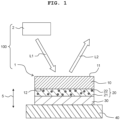
- an up-down direction 5 (corresponding to a "first direction" of the present invention) is defined with a state that the light source apparatus 100 is installed to be usable (a state depicted in FIG. 1 ), as the reference.
- the light source apparatus 100 according to the present embodiment is provided with a wavelength conversion member 1 and a light source 2.
- the light source 2 is a LED (Light Emitting Diode) or a LD (Laser Diode), and emits a light L1 in a predetermined wavelength region.
- the wavelength conversion member 1 includes a fluorescent body 10 which will be described later on.
- the fluorescent body 10 In a case that the light L1 comes into the fluorescent body 10, the fluorescent body 10 emits a light of a wavelength which is different from that of the light L 1, as fluorescence. In the wavelength conversion member 1, the fluorescent emitted by the fluorescent body 10 is radiated, as a light L2, in a predetermined direction together with the light L1 which has not contributed to the generation of the fluorescence in the fluorescent body 10.
- the light source apparatus 100 of the present embodiment is a light source apparatus of the reflective type, and is usable in a variety of kinds of optical devices such as a head lamp, an illumination device, a projector, etc.
- the wavelength conversion member 1 is provided with the fluorescent body 10, a reflective film 20, a joining layer 30 and a heat-dissipating member 40. As depicted in FIG. 1 , the fluorescent body 10, the reflective film 20, the joining layer 30 and the heat-dissipating member 40 are stacked in this order in the up-down direction.
- the fluorescent body 10 is a ceramic sintered body which has a shape of a plate and which is provided with a fluorescent phase including crystal particles having the fluorescence (fluorescence property), and a translucent phase including crystal particles (crystal grains) having the translucency.
- a fluorescent phase including crystal particles having the fluorescence (fluorescence property)
- a translucent phase including crystal particles (crystal grains) having the translucency.
- an upper surface (a surface on the opposite side to the reflective film 20) of the fluorescent body 10 is referred to as a first surface 11, and a lower surface (a surface facing or opposed to the reflective film 20) of the fluorescent body 10 is referred to as a second surface 12.
- the fluorescent phase of the fluorescent body 10 absorbs the light L1 coming thereinto from the first surface 11, and emits a light of a different wavelength from that of the light L1. In other words, with the light L1 coming into the fluorescent phase of the fluorescent body 10 as an excitation light, the fluorescent phase emits fluorescent of a different wavelength from that of the excitation
- the crystal particles of the translucent phase has a composition represented by a chemical formula Al 2 O 3
- the crystal particles of the fluorescent phase has a composition represented by a chemical formula A 3 B 5 O 12 :Ce (a so-called garnet structure). Note that "A 3 B 5 O 12 :Ce" indicates that Ce is solid-dissolved in A 3 B 5 O 12 and that a part of the element A is substituted for Ce.
- Each of the element A and the element B in the chemical formula "A 3 B 5 O 12 :Ce" is composed of at least one kind of element selected from the following element groups as follows:
- the ceramic sintered body as the fluorescent body 10
- the light is scattered in the interface between the fluorescent phase and the translucent phase, thereby making it possible to reduce the angle dependency of the color of the light. With this, it is possible to improve the color uniformity.
- the reflective film 20 is stacked on the second surface 12 of the fluorescent body 10.
- the reflective film 20 reflects a light passing through the fluorescent body 10 and a light generated in the fluorescent body 10.
- the reflective film 20 is provided with a metal layer 21 (for example, silver (Ag), platinum (Pt), aluminum (Al), silver alloy, etc.), and a plurality of crystalline oxide particles 22 which are dispersed in the inside of the metal layer 22.
- the crystalline oxide particles 22 are an example of "crystalline ceramic particles" of the present invention.
- the crystalline oxide particles 22 are, for example, crystal of Al 2 O 3 , YAG, TiO 2 , Y 2 O 3 , SiO 2 , Cr 2 O 3 , Nb 2 O 5 , Ta 2 O 5 , etc., and do not include amorphous oxide particles such as glass.
- the joining layer 30 is arranged between the reflective film 20 and the heat-dissipating member 40, and is formed of an AuSn solder including gold (Au) and tin (Sn).
- the joining layer 30 joins the fluorescent body 10 and the heat-dissipating member 40 and transmits the heat generated in the fluorescent body 10 to the heat-dissipating member 40.
- the heat-dissipating member 40 is a member having a shape of a flat plate and formed, for example, of a material which has a thermal conductivity higher than that of the fluorescent body 10, and which is exemplified, for example, by copper, a copper-molybdenum alloy, a copper-tungsten alloy, aluminum, aluminum nitride, etc.
- the heat-dissipating member 40 dissipates, to the outside, the heat of the fluorescent body 10 transmitted thereto via the joining layer 30.
- the wavelength conversion member 1 was produced by the following procedure (see FIG. 2 ). First, the materials were weighed so that the ratio of the fluorescent phase to the translucent phase became to be 6:4 (step S11). Next, the weighed materials were charged into a ball mil together with ethanol, and was subjected to a crushing and mixing for 16 hours (step S12) so as to obtain a slurry. Note that pure water (purified water) may be used, instead of using the ethanol. Next, the slurry obtained by the crushing and mixing was dried and granulated, and then a binder and water were added thereto (step S13).
- step S14 mixing (kneading) was performed while applying a shearing force so as to thereby produce a clay (kneaded clay) which was then molded into a sheet shape by an extrusion molding apparatus (step S14).
- the produced molding (compact) undergoes sintering in the ambient atmosphere at approximately 1700°C (step S15).
- the obtained sintered body was cut to have a thickness of 250 ⁇ m, was subjected to a mirror finish for a surface thereof, thereby producing a fluorescent body 10.
- alumina powder An acrylic based binder and a solvent were added to silver (Ag) powder (average particle diameter: in a range of approximately 1 ⁇ m to approximately 100 ⁇ m) and alumina (Al 2 O 3 ) powder (average particle diameter: in a range of approximately 0.1 ⁇ m to approximately 10 ⁇ m) and was subjected to mixing (step S16).
- the alumina powder is adjusted to have a volume ratio preferably in a range of approximately 3% to approximately 50%, more preferably in a range of approximately 5% to approximately 20%.
- the alumina powder was adjusted to have a volume ratio of approximately 5%.
- the obtained slurry was coated on the second surface 12 of the fluorescent body 10, and was dried (step S17). Then, heating was performed in the ambient atmosphere up to a temperature not less than the melting point (961.8°C) of the silver (for example, up to 1000°C) (step S18). With this, the reflective film 20 was formed on the second surface 12 of the fluorescent body 10.
- step S19 a wavelength conversion member 1 which is a joined body of the fluorescent body 10 and the heat-dissipating member 40 was produced.
- the average particle diameter of the alumina particles dispersed in the reflective film 20 of the produced wavelength conversion member 1 was in a range of approximately 0.1 ⁇ m to approximately 10 ⁇ m.
- Example 1 in the formation of the reflective film 20, the heating was performed up to the temperature not less than the melting point of the silver.
- the melting point of the alumina is 2072°C which is very high, and the heating was performed not up to the melting point of the alumina in the formation of the reflective film 20. Accordingly, in the formation of the reflective film 20, although the silver particles are melted and the molten silver fluidly moves, the alumina particles do not fluidly move due to the crystallinity thereof. Due to this, the alumina particles do not gather in the interface between the reflective film 20 and the fluorescent body 10, thereby making it possible to disperse the alumina particles in the molten silver.
- the alumina particles dispersed in the inside of the reflective film 20 has a high translucency, it is possible to suppress any reduction in the amount of light due to the absorption of the light by the alumina particles.
- Example 1 the silver is baked on the surface of the fluorescent body 10 at a high temperature in the formation of the reflective film 20. Accordingly, it is possible to greatly enhance the adhesion strength between the reflective film and the surface of the fluorescent body, as compared with a case that a reflective film 20 of the silver is formed by the vapor deposition. Further, it is possible to form a thick reflective film, as compared with the case that the reflective film 20 of the silver is formed by the vapor deposition. Generally, in a case that the reflective film 20 of the silver is formed on the surface of the fluorescent body 10 by the vapor deposition, the limit for the thickness of the reflective film 20 of the silver is several hundred nm.
- Example 1 In contrast, in a case that the reflective film 20 of the silver is baked on the surface of the fluorescent body 10 as described above, it is possible to make the thickness of the reflective film 20 be great, as compared with the case that the reflective film is formed by the vapor deposition.
- Example 1 a reflective film 20 of which thickness is in a range of 5 ⁇ m to 10 ⁇ m was formed. Further, in the case that the reflective film 20 of the silver is baked on the surface of the fluorescent body 10 as described above, it is possible to form the reflective film 20 cheaply, as compared with the case that the reflective film is formed by the vapor deposition.
- Example 2 a wavelength conversion member 1 was produced in a method of production similar to that in Example 1, except that the oxide particles which are dispersed in the inside of the metal layer 22 are cerium-activated yttrium-aluminum-garnet (YAG:Ce) particles, rather than the alumina particles.
- YAG:Ce cerium-activated yttrium-aluminum-garnet
- the cerium-activated yttrium-aluminum-garnet (YAG:Ce) particles are simply referred to as "YAG particles".
- Example 2 the silver is baked on the surface of the fluorescent body 10 in the case of forming the reflective film 20, similarly to Example 1. Accordingly, it is possible to greatly enhance the adhesion strength between the reflective film and the surface of the fluorescent body, as compared with a case that a reflective film 20 of the silver is formed by the vapor deposition; and it is also possible to form a thick reflective film having a thickness in a range of 5 ⁇ m to 100 ⁇ m. Further, similarly to the alumina particles, since the YAG particles serve like nuclei which attract the molten silver, it is possible to inhibit partial aggregation of the molten silver and to spread the molten silver in the entirety of the second surface 12 of the fluorescent body 10.
- the YAG particles are a fluorescent body which absorbs the blue light and emits the yellow light. Accordingly, by dispersing the YAG particles in the inside of the reflective film 20, it is possible to increase an amount of the light in the inside of the reflective film 20.
- Example 3 a wavelength conversion member 1 was produced in a method of production similar to that in Example 1, except that alumina powder having an average particle diameter in a range of approximately 5 ⁇ m to 50 ⁇ m was used in the mixing of the alumina powder and the silver powder, and that a reflective film 20 having a thickness in a range of 10 ⁇ m to 150 ⁇ m was formed. Since the alumina powder having the average particle diameter in the range of approximately 5 ⁇ m to 50 ⁇ m was used, the average particle diameter of the alumina particles dispersed in the reflective film 20 of the produced wavelength conversion member 1 was in a range of approximately 5 ⁇ m to 50 ⁇ m. It was confirmed that the wavelength conversion member 1 of Example 3 also exhibited a similar effect to that of the wavelength conversion member 1 of Example 1.
- the wavelength conversion member 1 has the fluorescent body 10 which emits the fluorescence by the excitation light L1 and the reflective film 20 arranged on the side of the second surface 12 of the fluorescent body 10.
- the reflective film 20 has the metal layer 21 such as the silver, etc., and the crystalline oxide particles 22 which are dispersed in the inside of the metal layer 21.
- the melting point of the oxide particles 22 is higher than the melting point of the metal constructing the metal layer 21. Accordingly, it is possible to bake the metal layer on the surface of the fluorescent body 10 in a state that the heating is performed up to the temperature higher than the melting point of the metal constructing the metal layer 21. With this, it is possible to enhance the adhesion strength of the reflective film 20 with respect to the fluorescent body 10.
- the oxide particles 22 are not melt and do not fluidly move, and thus the oxide particles 22 do not gather to the interface between the reflective film 20 and the fluorescent body 10, which in turn makes it possible to disperse the oxide particles in the molten metal. Since the oxide particles 22 are dispersed in the molten metal, the viscosity of the molten metal is increased, thereby making it possible to suppress such a situation that the molten metal partially aggregates. With this, it is possible to suppress any lowering in the reflectivity of the reflective film 20.
- the oxide particles 22 (for example, the alumina particles or the YAG particles) has the translucency. With this, it is possible to suppress any lowering in the amount of the light due to the absorption of the light by the oxide particles 22. Further, the oxide particles having the translucency are exemplified, for example, by TiO 2 , Y 2 O 3 , SiO 2 , Cr 2 O 3 , Nb 2 O 5 , Ta 2 O 5 , etc., other than the alumina particles and the YAG particles.
- the oxide particles 22 are the oxide particles which emit a light by the excitation light (for example, the YAG particles), since the oxide particles 22 emit the light, it is possible to increase the amount of the light in the inside of the reflective film 20.
- the light-emitting oxide particles are exemplified, for example, by LuAG (lutetium aluminum garnet), etc., other than the YAG particles.
- the wavelength conversion member 1 is provided with the heat-dissipating member 40 which dissipates or releases the heat of the fluorescent body 10 to the outside.
- the fluorescent body 10 it is possible to effectively dissipate the heat, which is generated in a case that the fluorescence is emitted by the excitation light, to the outside, thereby making it possible to suppress any quenching due to the increase in the temperature of the fluorescent body 10. Accordingly, it is possible to suppress any lowering in the amount of the light radiated from the wavelength conversion member 1.
- the light source apparatus 100 is provided with the light source 2 which irradiates the fluorescent body 10 with the light L1.
- the reflective film 20 can be configured to have the thickness which is great as compared with a reflective film formed by the vapor deposition, which in turn makes it possible to increase the adhesion strength of the reflective film 20 with respect to the fluorescent body 10. With this, since it is possible to improve the thermal resistance of the reflective film 20, it is possible to increase the luminance of the light L1 coming into the fluorescent body 10, thereby making it possible to improve the light emission intensity of the light source apparatus 100.
- each of the fluorescent body 10 and the reflective film 20 is not limited to or restricted by the above-described material, and a suitable material may be used.
- the joining layer 30 is not limited to the AuSn solder formed of the gold and the tin, and may be a solder formed of another material or other materials, or may be obtained by baking fine powder, for example, of silver, copper (Cu), etc.
- the heat-dissipating member 40 may be a member having a single-layered structure made of the above-described material, or may be a member having a multi-layered structure made of a same kind of material or different materials.
- a metal layer for example, a thin film of gold (Au), a thin film of nickel (Ni), etc.
- the metal layer 21 of the reflective film 20 is formed of the silver
- the present invention is not limited to such an aspect. It is allowable to use, as the metal layer 21, a metal different from the silver (for example, an alloy such as a silver alloy, platinum, aluminum, etc.).
- the present invention is not limited to such an aspect. It is not necessarily indispensable that the particles dispersed in the inside of the metal layer 21 of the reflective film 20 are the alumina particles or the YAG particles; it is allowable that the particles dispersed in the inside of the metal layer 21 of the reflective film 20 are crystalline ceramic particles having a melting point higher than the melting point of the metal constructing the metal layer 21 of the reflective film 20.
- the crystalline ceramic particles are exemplified, for example, by: particles of a suitable oxide which are different from the alumina particles and the YAG particles, a suitable nitride, a suitable carbide, a suitable boride, a metallic particles of which surface is ceramicized, etc. Note that the crystalline ceramic particles do not include the amorphous oxide particles such as the glass, as described above.
- the oxide particles are stable in the ambient atmosphere. Accordingly, in a case that crystalline oxide particles are used, as the crystalline ceramic particles, as in the above-described embodiment, it is possible to perform the baking in the ambient atmosphere in which the baking temperature (burning temperature) can be easily adjusted, as in the above-described step S18.
- the particles of the ceramic sintered body constructing the fluorescent body 10 it is possible to make the difference between the coefficient of thermal expansion of the reflective film 20 and the coefficient of thermal expansion of the fluorescent body 10 be small, as compared with another case in which the particles of the ceramic sintered body constructing the fluorescent body 10 are not used as the crystalline ceramic particles, thereby making it possible to suppress the exfoliation between the reflective film 20 and the fluorescent body 10. Further, in a case that the ceramic particles make contact with the fluorescent body, there is such a possibility that the composition of each of the ceramic particles and the fluorescent body might be changed. However, in a case that the particles of the ceramic sintered body constructing the fluorescent body 10 are used as the crystalline ceramic particles, it is possible to suppress such a change in the composition.
- the reflective film 20 is directly baked on the second surface 12 of the fluorescent body 10, the present disclosure is not limited to such an aspect.
- it is allowable to form an adhesive film (tight contact film), an enhanced reflection film, etc., between the second surface 12 of the fluorescent body 10 and the reflective film 20.
- the adhesive film and the enhanced reflection film may be formed, for example, of a niobium oxide, a titanium oxide, a lanthanum oxide, a tantalum oxide, an yttrium oxide, a gadolinium oxide, a tungsten oxide, a hafnium oxide, an aluminium oxide, a silicon oxide, a chromium oxide, etc.
- each of the adhesive film and the enhanced reflection film may be a single-layered film formed of the above-described material, or may be a multi-layered film formed of a same kind of material or different materials. Even in a case that such an enhanced reflection film is formed on the second surface 12 of the fluorescent body 10, it is possible to strengthen the adhesive strength of the reflective film 20 with respect to the fluorescent body 10 (and with respect to the enhanced reflection film), similarly to Examples 1 and 2 as described above.
Landscapes
- Physics & Mathematics (AREA)
- Engineering & Computer Science (AREA)
- General Engineering & Computer Science (AREA)
- Optics & Photonics (AREA)
- General Physics & Mathematics (AREA)
- Spectroscopy & Molecular Physics (AREA)
- Microelectronics & Electronic Packaging (AREA)
- Optical Elements Other Than Lenses (AREA)
- Optical Filters (AREA)
Applications Claiming Priority (2)
| Application Number | Priority Date | Filing Date | Title |
|---|---|---|---|
| JP2021011731 | 2021-01-28 | ||
| PCT/JP2021/045813 WO2022163175A1 (ja) | 2021-01-28 | 2021-12-13 | 波長変換部材及びそれを備える光源装置 |
Publications (2)
| Publication Number | Publication Date |
|---|---|
| EP4286901A1 true EP4286901A1 (de) | 2023-12-06 |
| EP4286901A4 EP4286901A4 (de) | 2025-01-01 |
Family
ID=82653323
Family Applications (1)
| Application Number | Title | Priority Date | Filing Date |
|---|---|---|---|
| EP21923180.0A Pending EP4286901A4 (de) | 2021-01-28 | 2021-12-13 | Wellenlängenumwandlungselement und lichtquellenvorrichtung damit |
Country Status (7)
| Country | Link |
|---|---|
| US (1) | US11994284B2 (de) |
| EP (1) | EP4286901A4 (de) |
| JP (1) | JP7418621B2 (de) |
| KR (1) | KR102873963B1 (de) |
| CN (1) | CN115702370A (de) |
| TW (1) | TWI830134B (de) |
| WO (1) | WO2022163175A1 (de) |
Families Citing this family (1)
| Publication number | Priority date | Publication date | Assignee | Title |
|---|---|---|---|---|
| CN120320152B (zh) * | 2025-06-16 | 2025-08-29 | 华中科技大学 | 一种激光照明和显示用无机荧光转换元件及其制备与应用 |
Family Cites Families (15)
| Publication number | Priority date | Publication date | Assignee | Title |
|---|---|---|---|---|
| JP2004269290A (ja) * | 2003-03-06 | 2004-09-30 | Ngk Insulators Ltd | 透光性アルミナセラミックスの製造方法、透光性アルミナセラミックス、高圧放電灯用発光容器、造粒粉末および成形体 |
| JP5169106B2 (ja) * | 2007-09-26 | 2013-03-27 | ウシオ電機株式会社 | 光照射式加熱処理装置 |
| WO2010017523A1 (en) | 2008-08-08 | 2010-02-11 | Xicato, Inc. | Color tunable light source |
| WO2014123145A1 (ja) * | 2013-02-08 | 2014-08-14 | ウシオ電機株式会社 | 蛍光光源装置 |
| DE102013013296B4 (de) | 2013-08-12 | 2020-08-06 | Schott Ag | Konverter-Kühlkörperverbund mit metallischer Lotverbindung und Verfahren zu dessen Herstellung |
| JP6176224B2 (ja) | 2013-12-25 | 2017-08-09 | 日亜化学工業株式会社 | 半導体素子及びそれを備える半導体装置、並びに半導体素子の製造方法 |
| WO2017126441A1 (ja) * | 2016-01-22 | 2017-07-27 | 日本特殊陶業株式会社 | 波長変換部材および発光装置 |
| CN105762239B (zh) * | 2016-04-12 | 2018-11-06 | 杨阳 | 光转换装置及其制备方法和应用 |
| EP3508891A4 (de) * | 2016-08-30 | 2019-11-06 | Panasonic Intellectual Property Management Co., Ltd. | Farbumwandlungselement |
| JP6361995B2 (ja) * | 2017-01-20 | 2018-07-25 | ウシオ電機株式会社 | 発光素子、蛍光光源装置 |
| JP6955151B2 (ja) * | 2017-09-13 | 2021-10-27 | 日亜化学工業株式会社 | 光学部品、光学部品を用いた発光装置、及び光学部品の製造方法 |
| CN110017435A (zh) * | 2018-01-10 | 2019-07-16 | 深圳光峰科技股份有限公司 | 波长转换装置 |
| US11287107B2 (en) * | 2018-02-14 | 2022-03-29 | Ngk Spark Plug Co., Ltd. | Optical wavelength conversion device |
| JP7188893B2 (ja) | 2018-03-15 | 2022-12-13 | 日本特殊陶業株式会社 | 光波長変換部材及び光波長変換装置 |
| CN111063810B (zh) * | 2018-10-16 | 2021-11-12 | 深圳光峰科技股份有限公司 | 发光装置及其制备方法 |
-
2021
- 2021-12-13 US US18/245,275 patent/US11994284B2/en active Active
- 2021-12-13 WO PCT/JP2021/045813 patent/WO2022163175A1/ja not_active Ceased
- 2021-12-13 JP JP2022578125A patent/JP7418621B2/ja active Active
- 2021-12-13 CN CN202180040551.9A patent/CN115702370A/zh active Pending
- 2021-12-13 KR KR1020237003776A patent/KR102873963B1/ko active Active
- 2021-12-13 EP EP21923180.0A patent/EP4286901A4/de active Pending
-
2022
- 2022-01-27 TW TW111103535A patent/TWI830134B/zh active
Also Published As
| Publication number | Publication date |
|---|---|
| EP4286901A4 (de) | 2025-01-01 |
| WO2022163175A1 (ja) | 2022-08-04 |
| US11994284B2 (en) | 2024-05-28 |
| KR102873963B1 (ko) | 2025-10-20 |
| JP7418621B2 (ja) | 2024-01-19 |
| TW202235925A (zh) | 2022-09-16 |
| JPWO2022163175A1 (de) | 2022-08-04 |
| US20230383926A1 (en) | 2023-11-30 |
| KR20230029986A (ko) | 2023-03-03 |
| TWI830134B (zh) | 2024-01-21 |
| CN115702370A (zh) | 2023-02-14 |
Similar Documents
| Publication | Publication Date | Title |
|---|---|---|
| JP6688976B2 (ja) | 波長変換部材 | |
| TWI696685B (zh) | 光波長轉換裝置及光複合裝置 | |
| US11287107B2 (en) | Optical wavelength conversion device | |
| CN105481362A (zh) | 半导体发光设备以及使用所述半导体发光设备的光源设备 | |
| CN106195924A (zh) | 一种波长转换装置及其制作方法、相关发光装置 | |
| JP6943984B2 (ja) | 光波長変換装置及び発光装置 | |
| EP4286901A1 (de) | Wellenlängenumwandlungselement und lichtquellenvorrichtung damit | |
| EP4524624A1 (de) | Wellenlängenumwandlungselement und lichtquellenvorrichtung | |
| WO2021251252A1 (ja) | 蛍光板、波長変換部材、および、光源装置 | |
| US11796156B2 (en) | Fluorescent plate, wavelength conversion member, and light source device | |
| JP2013105647A (ja) | 光源装置、発光色度調整方法、光源装置の製造方法 | |
| TWI802899B (zh) | 螢光板、波長轉換構件及光源裝置 | |
| JP7808520B2 (ja) | 波長変換部材、波長変換装置、および、光源装置 | |
| JP5137395B2 (ja) | 発光装置 | |
| JP2022115222A (ja) | 波長変換部材及びそれを備える光源装置 | |
| JP2024099928A (ja) | 波長変換部材、波長変換装置、および、光源装置 | |
| JP2024099929A (ja) | 波長変換部材、波長変換装置、および、光源装置 |
Legal Events
| Date | Code | Title | Description |
|---|---|---|---|
| STAA | Information on the status of an ep patent application or granted ep patent |
Free format text: STATUS: THE INTERNATIONAL PUBLICATION HAS BEEN MADE |
|
| PUAI | Public reference made under article 153(3) epc to a published international application that has entered the european phase |
Free format text: ORIGINAL CODE: 0009012 |
|
| STAA | Information on the status of an ep patent application or granted ep patent |
Free format text: STATUS: REQUEST FOR EXAMINATION WAS MADE |
|
| 17P | Request for examination filed |
Effective date: 20230314 |
|
| AK | Designated contracting states |
Kind code of ref document: A1 Designated state(s): AL AT BE BG CH CY CZ DE DK EE ES FI FR GB GR HR HU IE IS IT LI LT LU LV MC MK MT NL NO PL PT RO RS SE SI SK SM TR |
|
| DAV | Request for validation of the european patent (deleted) | ||
| DAX | Request for extension of the european patent (deleted) | ||
| A4 | Supplementary search report drawn up and despatched |
Effective date: 20241204 |
|
| RIC1 | Information provided on ipc code assigned before grant |
Ipc: F21Y 115/30 20160101ALI20241128BHEP Ipc: F21Y 115/10 20160101ALI20241128BHEP Ipc: G02B 5/08 20060101ALI20241128BHEP Ipc: F21V 9/30 20180101ALI20241128BHEP Ipc: F21V 7/30 20180101ALI20241128BHEP Ipc: G02B 5/20 20060101AFI20241128BHEP |