EP4284152B1 - Erntemaschine zum schneiden oder herausziehen von pflanzenstängeln, methode zum schneiden oder herausziehen von pflanzenstängeln und verwendung zum schneiden oder herausziehen von hanf - Google Patents
Erntemaschine zum schneiden oder herausziehen von pflanzenstängeln, methode zum schneiden oder herausziehen von pflanzenstängeln und verwendung zum schneiden oder herausziehen von hanf Download PDFInfo
- Publication number
- EP4284152B1 EP4284152B1 EP22850605.1A EP22850605A EP4284152B1 EP 4284152 B1 EP4284152 B1 EP 4284152B1 EP 22850605 A EP22850605 A EP 22850605A EP 4284152 B1 EP4284152 B1 EP 4284152B1
- Authority
- EP
- European Patent Office
- Prior art keywords
- picking
- roller
- belt
- entrainment
- axis
- Prior art date
- Legal status (The legal status is an assumption and is not a legal conclusion. Google has not performed a legal analysis and makes no representation as to the accuracy of the status listed.)
- Active
Links
Images


Classifications
-
- A—HUMAN NECESSITIES
- A01—AGRICULTURE; FORESTRY; ANIMAL HUSBANDRY; HUNTING; TRAPPING; FISHING
- A01D—HARVESTING; MOWING
- A01D45/00—Harvesting of standing crops
- A01D45/06—Harvesting of standing crops of flax or similar fibrous plants
- A01D45/065—Harvesting of standing crops of flax or similar fibrous plants of fibrous plants other than flax, e.g. ramie, sisal, hemp, jute, Spanish grass, raffia
Definitions
- the invention relates to a harvesting machine for cutting or pulling out plant stems, and more particularly to guiding plant stems to a cutting or pulling means of the harvesting machine.
- the invention further relates to a method for cutting plant stems and a use of the harvesting machine or the method for cutting or pulling out of hemp.
- the harvesting machine comprises a cutting or pulling means.
- the plant stems are divided into swaths by means of pointed dividers while the harvesting machine is driven over the ground and guided to a gripping point between a picking belt and a picking roller.
- the front return roller is always pressed against the picking roller. After cutting or pulling up the plant stems, the plant stems are further discharged by picking belts.
- AT390862 , FR1281756 and GB158322 describe prior art harvesting machines for harvesting flax in which plant stems may bend forward due to contact and friction with the dividers. As a result, these known harvesting machines are less suitable for cutting or pulling up long plant stems.
- the present invention aims to solve at least some of the above problems or drawbacks.
- the present invention relates to a harvesting machine according to claim 1.
- the advantage of this harvesting machine is that the distance between the axis of the front return roller and the picking roller is greater than the sum of the radius of the front return roller and the radius of the picking roller, plus the thickness of the picking belt.
- This provides a free funnel-shaped access to a plant stalk gripping point between the picking belt and the picking roller.
- there is less resistance for the plant stems when approaching the gripping point so that the plant stems bend forward less when moving the harvesting machine according to the direction of travel and the risk of a chain reaction causing the harvesting machine to drive over the plant stems instead of cutting the plant stems or pulling them up, is greatly reduced.
- the entrainment belt or entrainment chain is located partly outside the perimeter of the divider, so that plant stems that come into contact with the divider are carried along by the entrainment belt or entrainment chain to the gripping point between the picking belt and the picking roller.
- plant stems encounter less resistance during travel of the harvesting machine in the direction of travel and the plant stems will bend forward even less in the direction of travel, so that the chance of the harvesting machine driving over the plant stems is further reduced.
- a specific preferred embodiment concerns a harvesting machine according to claim 2.
- An advantage of this embodiment is that the distance Y between the axis of the front return roller and the picking roller, in a direction transverse to the direction of travel, is equal to or greater than the sum of the radius of the front return roller and the radius of the picking roller.
- a plant stalk gripping point between the picking belt and the picking roller is freely accessible, viewed against the direction of travel, so that there is less friction between the plant stems themselves and between the plant stems and the dividers when approaching the gripping point, and as a result of which the resistance for the plant stems is reduced even further when approaching the gripping point.
- the present invention relates to a method according to claim 10.
- This method has the advantage, among other things, that the plant stems are guided to a plant stalk gripping point between the picking belt and the picking roller, the distance between the axis of the front return roller and the picking roller being greater than the sum of the radius of the front return roller and the picking roller, plus the thickness of the picking belt.
- there is a free funnel-shaped access to the plant stalk gripping point between the picking belt and the picking roller so that the plant stems experience less resistance when approaching the gripping point, so that the plant stems bend forward less during travel of the harvesting machine in the direction of travel. This greatly reduces the chance of the harvesting machine driving over the plant stems instead of cutting or pulling up the plant stems.
- the present invention relates to a use according to claim 15.
- Hemp stems are plants with very long stems up to three meters in length that are also very flexible.
- the harvesting machine will drive over the hemp stems instead of cutting or pulling up the hemp stems.
- a segment means one or more segments.
- Quoting numerical ranges by endpoints includes all integers, fractions and/or real numbers between the endpoints, these endpoints included.
- a wheel and roller are cylindrical bodies rotatable about the cylinder axis and suitable for supporting or guiding a belt or chain.
- a wheel has a radius greater than the dimension along the cylinder axis.
- a roller has a radius that is less than or equal to the dimension along the cylinder axis.
- a pyramid in this text is a prismatoid consisting of a polygon, regular or irregular, as a base and triangular side faces extending from each of the sides of the polygon to a common point.
- the common point is a top.
- a triangular pyramid is a pyramid with a triangle as its base.
- the invention relates to a harvesting machine for cutting or pulling up plant stems.
- the harvesting machine is movable in a direction of travel.
- the harvesting machine is a trailed harvesting machine or a self-propelled harvesting machine.
- the harvesting machine is preferably a self-propelled machine, and the harvesting machine comprises a drive motor as drive for self-propelling the harvesting machine.
- the harvesting machine comprises dividers for guiding plant stems to a cutting or pulling means.
- the dividers comprise a top.
- the top of the dividers faces in the direction of travel.
- the dividers are preferably elongated, with the dividers extending in the direction of travel.
- the dividers are formed by tubes and/or plates and/or other suitable materials.
- the dividers have an acute-angled triangle as perimeter when projected on a lying plane. Said perimeter of the dividers is preferably isosceles.
- the dividers may be contained in a volume, such as, for example, a triangular pyramid.
- the harvesting machine comprises a picking roller, a picking belt, guide rollers and a front return roller.
- the picking belt is arranged in a loop around the guide rollers and the front return roller.
- the picking belt is rotatable.
- the harvesting machine comprises a drive roller for driving the picking belt.
- the drive roller can be driven by an electric motor, a hydraulic motor or by coupling to a drive motor of the harvesting machine.
- the picking roller, the guide rollers and the front return roller are preferably drivable by contact with the picking belt. Viewed in the direction of travel, the front return roller is closer to the dividers than the guide rollers.
- the picking belt comprises teeth or a protrusion on a side facing a jacket surface of the front return roller and the front return roller comprises a groove in the jacket surface for receiving the teeth or protrusion.
- the guide rollers and any drive roller also comprise a jacket surface with a groove for receiving the teeth or the protrusion. This is also advantageous for positioning and maintaining a position of the picking belt on the guide rollers and any drive roller.
- the front return roller comprises an axis and a radius.
- the picking roller comprises an axis and a radius.
- the axis of the front return roller and the axis of the picking roller are parallel.
- the axis of the front return roller preferably lies in a standing plane parallel to the direction of travel.
- the axis of the picking roller preferably lies in a standing plane parallel to the direction of travel.
- the picking belt touches the picking roller. This forms a gripping point for gripping the plant stems between the picking belt and the picking roller.
- Axes of the picking roller and the front return roller that lie in a standing plane parallel to the direction of travel are advantageous for gripping upright plant stems.
- the axes of the picking roller and the front return roller preferably make an angle with a lying plane, for instance a ground, with the axes of the picking roller and the front return roller inclined from the lying plane in the direction of travel.
- This is advantageous for carrying along the plant stems in a direction away from the ground by the picking belt after being gripped. Gripping the plant stems is advantageous for controlled cutting of the plant stems by means of the cutting means because the plant stems are held upright during cutting and are pulled against the cutting means by movement of the picking belt. Gripping the plant stems is also advantageous for pulling the plant stems out of a ground. The plant stems are grasped in a substantially standing position and moved against the direction of travel by the picking belt, pulling the plant stems out of the ground and discharging them.
- the axes of the picking roller and the front return roller make an angle with a lying plane in order to pull the plant stems obliquely upwards from the ground. It will be apparent from this description to one skilled in the art that the picking belt and the picking roller can form the pulling means.
- Two adjacent dividers form a funnel to the picking roller and picking belt. This is advantageous in ensuring that all plant stems within the funnel formed by two adjacent dividers are gripped by the picking roller and the picking belt and are mowed by the cutting means or pulled out of the ground by the pulling means.
- the axis of the front return roller is positioned near a first of the two adjacent dividers and the axis of the picking roller is positioned near a second of the two adjacent dividers.
- a distance between the axis of the front return roller and the axis of the picking roller is greater than the sum of the radius of the front return roller and the radius of the picking roller, plus a thickness of the picking belt.
- the thickness of the picking belt is measured perpendicularly from a jacket surface of the front return roller where the picking belt overlies the jacket surface of the front return roller. This means that optional teeth or protrusion, as previously described, are not included in the thickness of the picking belt.
- Such a distance is advantageous because it provides a free funnel-shaped access to the plant stalk gripping point between the picking belt and the picking roller.
- the harvesting machine comprises a guide plate for clamping plant stems between the guide plate and the picking belt.
- the harvesting machine comprises pairs of picking belts and picking rollers.
- the first part and the second part of the plant stems come together, and the first part and the second part of the plant stems are clamped between the first picking belt and the second picking belt and the first part and the second part of the plant stems are carried along by the first picking belt and the second picking belt.
- a part of the first picking belt and the second picking belt are placed parallel next to each other over a length.
- a distance Y between the axis of the front return roller and the axis of the picking roller in a direction transverse to the direction of travel is equal to or greater than the sum of the radius of the front return roller and the radius of the picking roller.
- the distance Y is equal to or greater than the sum of the radius of the front return roller and the radius of the picking roller, plus the thickness of the picking belt.
- This embodiment is advantageous because the plant stalk gripping point between the picking belt and the picking roller is freely accessible, viewed against the direction of travel, so that there is less friction between the plant stems themselves and between the plant stems and the dividers when approaching the gripping point, and as a result of which the resistance for the plant stems is reduced even further when approaching the gripping point.
- a smallest angle ⁇ from a first line to the direction of travel is at least -10° and at most +45°.
- the smallest angle ⁇ is preferably at least -7°, more preferably at least -5°, even more preferably at least -2° and even more preferably at least 0°.
- the smallest angle ⁇ is preferably at most +40°, more preferably at most +35°, even more preferably at most +30° and even more preferably at most +25°.
- a positive angle ⁇ is in the same sense as a smallest angle ⁇ from a second line to the direction of travel.
- the first line is in line with a part of the picking belt. Said part of the picking belt connects the front return roller and the picking roller.
- the second line connects the axis of the front return roller and the axis of the picking roller.
- This embodiment is advantageous because the smallest angle ⁇ determines to what extent plant stems have to change direction in order to be guided via a funnel-shaped opening formed between the picking belt and the picking roller to the plant stalk gripping point and thus the extent to which the gripping point between the picking belt and the picking roller is more accessible to the plant stems.
- a large positive smallest angle ⁇ is disadvantageous because the plant stems experience a large displacement transverse to the direction of travel.
- a negative smallest angle ⁇ is even more disadvantageous because the plant stems now not only have to be moved in a direction transverse to the direction of travel, but also have to rotate around the front return roller, so that the gripping point between the picking belt and the picking roller is less accessible to the plant stems.
- the smallest angle ⁇ is an angle of at least -10° and at most +45°, plant stems must be changed in direction by the dividers more limitedly during guiding in order to end up in the funnel-shaped opening between the picking belt and the picking roller and finally to be gripped in the gripping point by the picking belt and the picking roller and the gripping point is more accessible.
- a positive smallest angle ⁇ is particularly advantageous because the plant stems do not have to rotate around the front return roller, so that the plant stems experience even less resistance.
- the axis of the front return roller is located within a divider.
- the axis of the front return roller is arranged at a distance X from the axis of the picking roller, according to the direction of travel.
- the distance X is equal to or greater than the sum of the radius of the front return roller and the radius of the picking roller.
- the distance X is equal to or greater than the sum of the radius of the front return roller and the radius of the picking roller, plus a thickness of the picking belt.
- the picking belt comprises an exterior for contact with the plant stems.
- the exterior of the picking belt is also the side of the picking belt that touches the picking roller.
- the picking belt is positioned from the front return roller with at least the outside of the picking belt outside the divider.
- This embodiment is advantageous because it allows the picking belt in the funnel formed by two dividers, wherein a first of the two dividers is the divider in which the axis of the front return roller is arranged, to run along part of the first divider.
- a first of the two dividers is the divider in which the axis of the front return roller is arranged, to run along part of the first divider.
- the distance X is at least 20% of a total distance along the direction of travel between the axis of the picking roller and the top of the divider, preferably at least 30%, more preferably at least 35%, even more preferably at least 37.5% and even more preferably at least 40%.
- This is advantageous because the picking belt runs along a substantial part of the first divider, while the front return roller is positioned maximally within the first divider.
- an angle ⁇ between a side of the first divider and a tangent to the exterior of the picking belt at the point where the exterior of the picking belt, viewed against the direction of travel, extends outside the first divider is at least 105°, preferably at least 115°, more preferably at least 120°, and even more preferably at least 125°.
- the angle ⁇ lies within the funnel formed by the two dividers. The angle ⁇ is directed to the top of the first divider.
- This embodiment is advantageous because it allows a gradual transition of the plant stems from a side of the first divider to the picking belt, so that the plant stems experience less resistance.
- the front return roller is preferably placed as close as possible to the top of the first divider, while at the same time the angle ⁇ is at least 105°.
- the harvesting machine comprises an entrainment belt or entrainment chain.
- the entrainment belt or entrainment chain is arranged in a loop around a front and a rear return wheel.
- the front return wheel and the rear return wheel each comprise an axis.
- the axis of the front return wheel and the axis of the rear return wheel are preferably parallel.
- the axis of the front return wheel and the axis of the rear return wheel are located within or near the base of the same divider.
- at least the front or the rear return wheel is drivable, for instance by an electric motor, by a hydraulic motor, or by coupling to the drive motor of the harvesting machine.
- a part of the entrainment belt or entrainment chain is located outside a perimeter of said divider. Said part of the entrainment belt or entrainment chain connects the front return wheel and the rear return wheel. Said part of the entrainment belt or entrainment chain is located in the funnel formed by two dividers, wherein a second of the two dividers is said divider, in which the axis of the front return wheel and the axis of the rear return wheel are placed.
- An advantage of this embodiment is that plant stems which come into contact with the second divider are carried along by the entrainment belt or entrainment chain to the gripping point between the picking belt and the picking roller. As a result, plant stems encounter less resistance during travel of the harvesting machine in the direction of travel and the plant stems will bend forward even less in the direction of travel, so that the chance of the harvesting machine driving over the plant stems is further reduced.
- the first divider in this embodiment is a standard divider, but can also be according to a previously described embodiment, wherein the axis of the front return roller is placed inside the first divider, and wherein the axis of the front return roller is positioned at a distance X according to the direction of travel from the axis of the picking roller.
- the rear return wheel and the picking roller are combined.
- the rear return wheel is preferably drivable by contact with the picking belt.
- This embodiment is advantageous because it does not require a specific rear return wheel, which saves both on components and on weight.
- This embodiment is also advantageous because plant stems are smoothly transferred from the entrainment belt or entrainment chain to the picking roller, so that resistance when gripping the plant stems between the picking belt and the picking roller is reduced.
- the picking roller comprises a jacket surface.
- the entrainment belt or entrainment chain lies in the recess around the picking roller.
- the recess forms the rear return wheel for the entrainment belt or chain.
- a surface of the entrainment belt or entrainment chain in the recess is at most equal to or lower than the jacket surface of the picking roller. Said surface of the entrainment belt or entrainment chain is directed at the funnel formed by two dividers.
- This embodiment is advantageous because the entrainment belt or entrainment chain does not protrude from the jacket surface of the picking roller, so that the picking belt continues to touch the jacket surface of the picking belt, without being pushed away from it by the entrainment belt or entrainment chain. As a result, plant stems are gripped over a full height of the picking roller between the picking roller and the picking belt, and not just at the level of the entrainment belt or entrainment chain.
- the entrainment belt is a toothed belt. Teeth of the toothed belt face the picking belt. A toothed belt is advantageous for improved entrainment of the plant stems by the belt due to an increased uneven contact surface.
- the teeth of the toothed belt are at most equal to or lower than the jacket surface of the picking roller, as in a previously described embodiment.
- the toothed belt is a toothed V-belt.
- the toothed V-belt comprises teeth on a first side of the toothed V-belt and a V-shaped surface on a second side of the toothed V-belt. The second side is opposite the first side.
- Teeth of the toothed V-belt are directed towards the picking belt as previously described.
- the V-shaped surface is directed towards the front return wheel and the rear return wheel.
- a toothed V-belt is advantageous for automatically centering the toothed V-belt in a groove in the front return wheel and the rear return wheel, preventing the toothed V-belt from slipping off the front return wheel or the rear return wheel, if at all.
- said groove is the recess in the picking roller.
- the entrainment chain comprises protrusions transverse to the surface of the entrainment chain.
- the protrusions are advantageous for improved entrainment of the plant stems by the entrainment chain through an increased uneven contact surface.
- the protrusions of the entrainment chain are at most equal to or lower than the jacket surface of the picking roller, as in a previously described embodiment.
- a bisector of a smallest angle ⁇ between a third line and a first line makes a smallest angle ⁇ of at least -15° and at most +15° from the bisector to the direction of travel.
- the smallest angle ⁇ is preferably at least -10°, more preferably at least -8°, even more preferably at least -6° and even more preferably at least -5°.
- the smallest angle ⁇ is preferably at most +10°, more preferably at most +8°, even more preferably at most +6° and even more preferably at most +5°.
- a positive angle ⁇ is in the same sense as the smallest angle ⁇ from the third line to the first line.
- the first line is in line with a part of the picking belt. Said part of the picking belt connects the front return roller and the picking roller.
- the third line is in line with the part of the entrainment belt or entrainment chain which is located outside the perimeter of said divider. This is the said part of the entrainment belt or entrainment chain that is located in the funnel formed by two dividers, as in a previously described embodiment.
- This embodiment is advantageous because the smallest angle ⁇ defines a funnel-shaped opening formed between the picking belt and the picking roller to the plant stalk gripping point. Because the bisector of the smallest angle ⁇ makes a smallest angle ⁇ of at least -15° and at most +15° with the direction of travel, plant stems must be changed very little in direction by the dividers during guiding in order to end up in the funnel-shaped opening between the picking belt and the picking roller and finally to be gripped in the gripping point by the picking belt and the picking roller. As a result, there is very little friction between the plant stems themselves and the plant stems and the dividers when approaching the gripping point, so that the plant stems bend forward less and the chance of the harvesting machine driving over the plant stems is greatly reduced.
- the smallest angle ⁇ is at least 12° and at most 35°.
- the smallest angle ⁇ is preferably at least 13°, more preferably at least 15°, even more preferably at least 17° and even more preferably at least 19°.
- the smallest angle ⁇ is preferably at most 32°, more preferably at most 29°, even more preferably at most 26° and even more preferably at most 23°.
- a smallest angle ⁇ within the given range is advantageous because the funnel-shaped opening is sufficiently narrow so that plant stems can be successfully gripped between the picking belt and the picking roller at the gripping point and sufficiently wide not to cause great friction between plant stems when approaching the gripping point.
- the axis of the front return roller is placed within a first divider, the axis of the front return roller being placed at a distance X from the axis of the picking roller according to the direction of travel, and the axis of the front and rear return wheel of the entrainment belt or entrainment chain is located within a second divider.
- the first and second dividers are adjacent to each other.
- the part of the jacket surface of the front return roller that is positioned outside the divider faces a side of the second divider.
- the part of the entrainment belt or entrainment chain that is located outside the perimeter of the second divider faces a side of the first divider.
- the gripping point between the picking belt and the picking roller is located between the first divider and the second divider.
- This embodiment combines advantages of a previously described embodiment in which the axis of the front return roller is placed within a divider and a previously described embodiment in which the axis of the front and rear return wheel is located within a divider.
- This embodiment has the additional advantage that the angle ⁇ is smaller compared to an embodiment in which the front return roller is not placed inside the first divider.
- the invention in a second aspect, relates to a method for cutting or pulling up plant stems.
- the method comprises the steps of:
- the harvesting machine is a trailed harvesting machine or is a self-propelled harvesting machine.
- the picking belt is arranged in a loop around guide rollers and a front return roller.
- the picking belt is rotatable.
- the harvesting machine comprises a drive roller for driving the picking belt.
- the drive roller can be driven by an electric motor, a hydraulic motor or by coupling to a drive motor of the harvesting machine.
- the picking roller, the guide rollers and the front return roller are preferably drivable by contact with the picking belt. Viewed in the direction of travel, the front return roller is closer to the dividers than the guide rollers.
- the front return roller comprises an axis and a radius.
- the picking roller comprises an axis and a radius.
- the axis of the front return roller and the axis of the picking roller are parallel.
- the axis of the front return roller preferably lies in a standing plane parallel to the direction of travel.
- the axis of the picking roller preferably lies in a standing plane parallel to the direction of travel.
- the picking belt touches the picking roller. This forms a gripping point for gripping the plant stems between the picking belt and the picking roller.
- Two adjacent dividers form a funnel to the picking roller and picking belt.
- a distance between the axis of the front return roller and the axis of the picking roller is greater than the sum of the radius of the front return roller and the radius of the picking roller, plus a thickness of the picking belt.
- the thickness of the picking belt is measured perpendicularly from a jacket surface of the front return roller where the picking belt overlies the jacket surface of the front return roller.
- This method has the advantage, among other things, that the plant stems are guided to a plant stalk gripping point between the picking belt and the picking roller, wherein there is a free funnel-shaped access to the plant stalk gripping point between the picking belt and the picking roller, so that the plant stems experience less resistance when approaching the gripping point, so that the plant stems bend forward less during travel of the harvesting machine in the direction of travel. This greatly reduces the chance of the harvesting machine driving over the plant stems instead of cutting or pulling up the plant stems.
- a distance Y between the axis of the front return roller and the axis of the picking roller in a direction transverse to the direction of travel is equal to or greater than the sum of the radius of the front return roller and the radius of the picking roller.
- the distance Y is equal to or greater than the sum of the radius of the front return roller and the radius of the picking roller, plus the thickness of the picking belt.
- This embodiment is advantageous because the plant stalk gripping point between the picking belt and the picking roller is freely accessible, viewed against the direction of travel, so that there is less friction between the plant stems themselves and between the plant stems and the dividers when approaching the gripping point, and as a result of which the resistance for the plant stems is reduced even further when approaching the gripping point.
- the plant stems are carried along by the picking belt from a distance X from an axis of the picking roller.
- the distance X is equal to or greater than the sum of the radius of the front return roller and the radius of the picking roller.
- the distance X is equal to or greater than the sum of the radius of the front return roller and the radius of the picking roller, plus a thickness of the picking belt.
- This embodiment is advantageous because plant stems in a funnel formed by two dividers, of which the first divider is one of the two dividers, are already carried along by the picking belt, which reduces the friction between the first divider and the plant stems and causes the plant stems to bend forward less and the chance of the harvesting machine driving over the plant stems is greatly reduced.
- the distance X is at least 20% of a total distance along the direction of travel between the axis of the picking roller and the top of the first divider, preferably at least 30%, more preferably at least 35%, even more preferably at least 37.5% and even more preferably at least 40%.
- This is advantageous because the picking belt runs along a substantial part of the first divider, while the front return roller is positioned maximally within the first divider.
- plant stems are carried along by an entrainment belt or entrainment chain on a side of a second divider while being guided between two dividers to a cutting or pulling means.
- the entrainment belt or entrainment chain is arranged in a loop around a front return wheel and a rear return wheel. Part of the entrainment belt or entrainment chain is located in a funnel formed by two dividers, the second divider being one of the two dividers.
- the front return wheel and the rear return wheel each comprise an axis.
- the axis of the front return wheel and the axis of the rear return wheel are preferably parallel.
- the axis of the front return wheel and the axis of the rear return wheel are located within the second divider.
- at least the front or rear return wheel is driven, for instance by an electric motor, by a hydraulic motor or by the engine of the harvesting machine.
- An advantage of this embodiment is that plant stems which come into contact with the second divider are carried along by the entrainment belt or entrainment chain to the gripping point between the picking belt and the picking roller. As a result, plant stems encounter less resistance during travel of the harvesting machine in the direction of travel and the plant stems will bend forward even less in the direction of travel, so that the chance of the harvesting machine driving over the plant stems is further reduced.
- the rear return wheel is combined with the picking drum.
- the rear return wheel is preferably driven by contact with the picking belt.
- This embodiment is advantageous because it does not require a specific rear return wheel, which saves both on components and on weight of the harvesting machine.
- This embodiment is also advantageous because plant stems are smoothly transferred from the entrainment belt or entrainment chain to the picking roller, so that resistance when gripping the plant stems between the picking belt and the picking roller is reduced.
- the plant stems are transferred to the picking roller and picking belt during the guiding of the entrainment belt or entrainment chain.
- the picking roller comprises a jacket surface. There is a recess in the jacket surface for the entrainment belt or entrainment chain.
- the entrainment belt or entrainment chain lies in the recess around the picking roller.
- the recess forms the rear return wheel for the entrainment belt or chain.
- a surface of the entrainment belt or entrainment chain in the recess is at most equal to or lower than the jacket surface of the picking roller. Said surface of the entrainment belt or entrainment chain is directed at the funnel formed by two dividers.
- This embodiment is advantageous because the entrainment belt or entrainment chain does not protrude from the jacket surface of the picking roller, so that the picking belt continues to touch the jacket surface of the picking belt, without being pushed away from it by the entrainment belt or entrainment chain.
- plant stems are gripped over a full height of the picking roller between the picking roller and the picking belt, and not only at the level of the entrainment belt or entrainment chain.
- plant stems are better gripped and the chance that the plant stems bend forward during cutting according to the direction of travel and that the harvesting machine drives over the plant stems is reduced.
- a method according to the second aspect is preferably carried out with a harvesting machine according to the second aspect and that a harvesting machine according to the first aspect is preferably configured for carrying out a method according to the second aspect.
- a harvesting machine according to the first aspect is preferably configured for carrying out a method according to the second aspect.
- the invention relates to a use of a harvesting machine according to the first aspect or a method according to the second aspect for cutting or pulling up hemp stems.
- Hemp stems are plants with very long stems up to three meters in length that are also very flexible.
- the hemp stems will bend forward in the direction of travel when approaching a gripping point between a picking roller and picking belt due to mutual friction and due to friction with the dividers, and that the harvesting machine will drive over the hemp stems instead of cutting or pulling up the hemp stems.
- this chance is greatly reduced.
- a fourth aspect relates to a harvesting machine for cutting or pulling up plant stems.
- the harvesting machine is movable in a direction of travel, wherein the harvesting machine comprises dividers for guiding plant stems to a cutting or pulling means, a picking roller, a picking belt, guide rollers and a front return roller, wherein the picking belt is arranged in a loop around the guide rollers and the front return roller, with two dividers forming a funnel to the picking roller and the picking belt, with the picking belt touching the picking roller, with the front return roller and the picking roller comprising an axis and a radius, with the axes of the front return roller and the picking roller being parallel, the harvesting machine comprising an entrainment belt or entrainment chain, the entrainment belt or chain being arranged in a loop around a front and a rear return wheel, the front and rear return wheel comprising an axis, the axis of the front and rear return wheel being located within the same divider, wherein part of the entrainment belt or entrainment chain is located outside a perimeter of said
- the advantage of this harvesting machine is that the harvesting machine comprises an entrainment belt or chain, wherein part of the entrainment belt or chain is located outside the perimeter of the divider, so that plant stems that come into contact with the divider are carried by the entrainment belt or entrainment chain to a gripping point between the picking belt and the picking roller.
- plant stems encounter less resistance during travel of the harvesting machine in the direction of travel and the plant stems will bend forward less in the direction of travel, so that the chance of the harvesting machine driving over the plant stems is reduced.
- a harvesting machine according to the fourth aspect can be combined with one or more embodiments of a harvesting machine according to the first aspect, even if the distance between the axis of the front return roller and the axis of the picking roller is smaller than or equal to the sum of the radius of the front return roller and the radius of the picking roller, plus a thickness of the picking belt.
- Figure 1 shows a partial plan view of a prior art harvesting machine.
- the harvesting machine drives in a direction of travel (20) over a ground with plant stems (1).
- the direction of travel (20) is indicated with an arrow in Figure 1 .
- the plant stems (2) are arranged in rows parallel to the direction of travel (20) on the ground with plant stems (1). It will be apparent to one skilled in the art that the plant stems (1) may also be arranged in rows perpendicular to or at an angle to the direction of travel (20).
- the harvesting machine comprises dividers (3).
- the dividers (3) comprise a top (10).
- the top (10) faces in the direction of travel (20).
- Two adjacent dividers (3) form a funnel to a picking roller (6) and a picking belt (7).
- the picking belt (7) touches the picking roller (6).
- the picking belt (7) is arranged in a loop around guide rollers (11) and a front return roller (4). Only part of the loop is visible in Figure 1 .
- the picking belt (7) is rotatable. Viewed in the direction of travel (20), the front return roller (4) is closer than the guide rollers (11) to the dividers (3).
- the front return roller (4) and the picking roller (6) each comprise an axis and a radius.
- the axis of the front return roller (4) and the axis of the picking roller (6) are parallel and lie in a standing plane parallel to the direction of travel (20).
- a smallest angle ⁇ (14) from a first line (21) to the direction of travel (20) is indicated.
- the first line (21) is in line with the picking belt (7), with the part of the picking belt (7) connecting the front return roller (4) and the picking roller (6).
- the first line (21) is a tangent to the front return roller (4) and the picking roller (6).
- Figure 1 also shows a smallest angle ⁇ (25) from a second line (22) to the direction of travel (20).
- the second line (22) connects the axis of the front return roller (4) with the axis of the picking roller (6).
- a positive angle ⁇ (14) is in the same sense as the smallest angle ⁇ (25).
- the smallest angle ⁇ (14) is -38° in this embodiment.
- Figure 2 shows a partial plan view of a harvesting machine.
- the harvesting machine is very similar to the prior art harvesting machine in Figure 1 .
- a distance Y between the axis of the front return roller (4) and the axis of the picking roller (6) in a direction transverse to the direction of travel (20) is greater than the sum of the radius of the front return roller (4) and the radius of the picking roller (6).
- the plant stems (2) gripping point (5) between the picking belt (7) and the picking roller (6) is freely accessible, viewed against the direction of travel (20).
- the smallest angle ⁇ (14) is 20° in this embodiment.
- Figure 3 shows a partial plan view of a harvesting machine according to an embodiment of the present invention.
- the harvesting machine is very similar to the harvesting machine in Figure 2 .
- the harvesting machine further comprises an entrainment belt or entrainment chain (8).
- the entrainment belt or entrainment chain (8) is arranged in a loop around a front return wheel (9) and the picking roller (6).
- the front return wheel (9) comprises an axis.
- the axis of the front return wheel (9) and the axis of the picking roller (6) are parallel.
- Part of the entrainment belt or entrainment chain (8) is located outside a perimeter of a second divider (26). Said part of the entrainment belt or entrainment chain (8) connects the front return roller (9) and the picking roller (6).
- Said part of the entrainment belt or entrainment chain (8) is located in the funnel formed by two dividers (3).
- the picking roller (6) comprises a jacket surface.
- the recess (12) is not visible in Figure 3 .
- a smallest angle ⁇ (17) between a third line (23) and the first line (21) is indicated.
- the first line (21) is in line with a part of the picking belt (7), with the part of the picking belt (7) connecting the front return roller (4) and the picking roller (6).
- the third line (23) is in line with the part of the entrainment belt or entrainment chain (8) which is located outside the perimeter of the second divider (26).
- the smallest angle ⁇ (17) is 33° in this embodiment.
- a bisector (19) divides the smallest angle ⁇ (17) into two equal angles.
- the bisector (19) makes a smallest angle ⁇ (15) from the bisector (19) to the direction of travel (20).
- a positive angle ⁇ (15) is in the same sense as the smallest angle ⁇ (17) from the third (23) line to the first line (21).
- the smallest angle ⁇ (15) is 5° in this embodiment.
- the smallest angle ⁇ (14) is 22° in this embodiment.
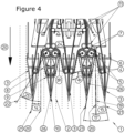
- Figure 4 shows a partial plan view of a harvesting machine according to another embodiment of the present invention.
- the harvesting machine is very similar to the harvesting machine in Figure 3 .
- the axis of the front return roller (4) is located within a first divider (3).
- the axis of the front return roller (4) is positioned according to the direction of travel (20) at a distance X (18) from the axis of the picking roller (6).
- the distance X (18) is at least 20% of a total distance according to the direction of travel (20) between the axis of the picking roller (6) and the top (10) of the first divider (3).
- the picking belt (7) comprises a jacket surface for contact with the plant stems.
- the exterior of the picking belt (7) is also the side that touches the picking roller (6).
- the picking belt (7) is positioned, from the front return roller (4), with the exterior outside of the first divider (3).
- an angle ⁇ (16) is indicated between a side of the first divider (3) and a tangent on the exterior of the picking belt (7). The tangent is at the point where the exterior of the picking belt (7), seen against the direction of travel (20), ends up outside of the first divider (3).
- the angle ⁇ (16) is 125° in this embodiment.
- the smallest angle ⁇ (17) is 22° in this embodiment.
- the smallest angle ⁇ (15) is -1.5° in this embodiment.
- the smallest angle ⁇ (14) is 10° in this embodiment.
- Figure 5A shows a detail view of an entrainment belt and a picking belt of a harvesting machine according to an embodiment of the present invention.
- the detailed view corresponds to an embodiment as shown in Figure 3 .
- the entrainment belt or entrainment chain (8) is a toothed belt in this embodiment.
- Figure 5A clearly shows how the toothed belt is placed in a recess (12) in the picking roller (6) and that the teeth of the toothed belt also do not protrude above the jacket surface of the toothed belt.
- the picking belt (7) comprises a protrusion (13) on a side facing the front return roller (4).
- the protrusion (13) runs in a groove on the jacket surface of the front return roller (4).
- Figure 5B shows a cross-sectional view along line A-A of a picking roller of a harvesting machine according to an embodiment of the present invention.
- This embodiment corresponds to an embodiment as shown in Figure 5A .
- Line A-A is shown in Figure 5A .
- Figure 5B the recess (12) for the entrainment belt or entrainment chain (8) is clearly visible. It is also clearly visible that the entrainment belt or entrainment chain (8) does not protrude above the jacket surface of the picking roller (6), so that the picking belt (7) makes contact over the entire height of the picking roller (6).
Landscapes
- Life Sciences & Earth Sciences (AREA)
- Botany (AREA)
- Environmental Sciences (AREA)
- Harvesting Machines For Root Crops (AREA)
Claims (15)
- Erntemaschine zum Schneiden oder Ausziehen von Pflanzenstängeln (2), wobei die Erntemaschine in einer Fahrtrichtung (20) verfahrbar ist, wobei die Erntemaschine Teiler (3, 26) zum Führen von Pflanzenstängeln (2) zu einer Schneid- oder Zieheinrichtung, eine Pflückrolle (6), ein Pflückband (7), Führungsrollen (11) und eine vordere Umlenkrolle (4) aufweist, wobei das Pflückband in einer Schleife um die Umlenkrollen (11) und die vordere Umlenkrolle (4) angeordnet ist, wobei zwei Teiler (3, 26) einen Trichter zu der Pflückrolle (6) und dem Pflückband (7) bilden, wobei das Pflückband (7) die Pflückrolle (6) berührt, wobei die vordere Umlenkrolle (4) und die Pflückrolle (6) eine Achse und einen Radius aufweisen, wobei die Achsen der vorderen Umlenkrolle (4) und der Pflückrolle (6) parallel sind, wobei ein Abstand zwischen der Achse der vorderen Umlenkrolle (4) und der Achse der Pflückrolle (6) größer ist als die Summe aus dem Radius der vorderen Umlenkrolle (4) und dem Radius der Pflückrolle (6) plus einer Dicke des Pflückbandes (7), dadurch gekennzeichnet, daß die Ernte-maschine einen Mitnehmerriemen oder eine Mitnehmerkette (8) umfasst, wobei der Mitnehmerriemen oder die Kette (8) in einer Schleife um ein vorderes (9) und ein hinteres Umlenkrad angeordnet ist, das vordere (9) und das hintere Umlenkrad eine Achse aufweisen, wobei die Achse des vorderen (9) und des hinteren Umlenkrades innerhalb desselben Teilers (26) angeordnet ist, wobei ein Teil des Mitnehmerbandes oder der Mit-nehmerkette (8) außerhalb eines Umfangs des Teilers (26) angeordnet ist, und wobei der Teil des Mitnehmerbandes oder der Mitnehmerkette (8) das vordere (9) und das hintere Umlenkrad verbindet.
- Erntemaschine nach Anspruch 1, dadurch gekennzeichnet, daß ein Abstand Y (24) zwischen der Achse der vorderen Umlenkrolle (4) und der Achse der Pflückrolle (6) in einer Richtung quer zur Fahrtrichtung (20) gleich oder größer ist als die Summe aus dem Radius der vorderen Umlenkrolle (4) und dem Radius der Pflückrolle (6).
- Erntemaschine nach Anspruch 1 oder 2, dadurch gekennzeichnet, daß ein kleinster Winkel β (14) von einer ersten Linie (21) zur Fahrtrichtung (20) mindestens -10° und höchstens +45° beträgt, wobei ein positiver Winkel β (14) im gleichen Sinne wie ein kleinster Winkel α (25) von einer zweiten Linie (22) zur Fahrtrichtung (20) ist, wobei die erste Linie (21) mit einem Teil des Pflückbandes (7) übereinstimmt, wobei der Teil des Pflück-bandes (7) die vordere Umlenkrolle (4) und die Pflückrolle (6) verbindet, und wobei die zweite Linie (22) die Achse der vorderen Umlenkrolle (4) und die Achse der Pflückrolle (6) verbindet.
- Erntemaschine nach einem der vorhergehenden Ansprüche 1 bis 3, dadurch gekennzeichnet, daß die Achse der vorderen Umlenkrolle (4) in einer Trennwand (3) angeordnet ist, wobei die Achse der vorderen Um-lenkrolle (4) in einem Abstand X (18) von der Achse der Pflückrolle (6) gemäß der Fahrtrichtung (20) angeordnet ist, wobei der Abstand X (18) gleich oder größer ist als die Summe des Radius der vorderen Umlenkrolle (4) und des Radius der Pflückrolle (6), und wobei das Pflückband (7) von der vorderen Umlenkrolle (4) aus so positioniert ist, daß sich zumindest ein Teil des Pflückbandes (7) außerhalb des Teilers (3) befindet.
- Erntemaschine nach einem der vorhergehenden Ansprüche 1-4, dadurch gekennzeichnet, daß das hintere Umlenkrad und die Pflückrolle (6) kombiniert sind.
- Erntemaschine nach Anspruch 5, dadurch gekennzeichnet, daß die Pflückrolle (6) eine Mantelfläche aufweist, wobei die Mantelfläche eine Aussparung (12) für das Mitnehmerband oder die Mitnehmerkette (8) aufweist, wobei eine Oberfläche des Mitnehmerbandes oder der Mit-nehmerkette (8) in der Aussparung (12) höchstens gleich oder niedriger ist als die Mantelfläche der Pflückrolle (6).
- Erntemaschine nach einem der vorhergehenden Ansprüche 1-6, dadurch gekennzeichnet, daß das Mitnehmerband (8) ein Zahnriemen ist.
- Erntemaschine nach einem der vorhergehenden Ansprüche 1-7, dadurch gekennzeichnet, daß eine Winkelhalbierende (19) eines kleinsten Winkels λ (17) zwischen einer dritten Linie (23) und einer ersten Linie (21) einen kleinsten Winkel θ (15) von mindestens -15° und höchstens +15° von der Winkelhalbierenden (19) zur Fahrtrichtung (20) aufweist, wodurch ein positiver Winkel θ (15) im gleichen Sinne wie der kleinste Winkel λ (17) von der dritten Linie (23) zur ersten Linie (21) entsteht, die erste Linie (21) in einer Linie mit einem Teil des Pflückbandes (7) liegt, wobei der Teil des Pflückbandes (7) die vordere Umlenkrolle (4) und die Pflückrolle (6) verbindet, und wobei die dritte Linie (23) in einer Linie mit dem Teil des Mitnahmebandes oder der Mitnahmekette (8) liegt, der außerhalb des Umfangs des Teilers (26) liegt.
- Erntemaschine nach Anspruch 4 und einem der vorhergehenden Ansprüche 5 bis 8, dadurch gekennzeichnet, daß die Achse der vor-deren Umlenkrolle (4) in einem ersten Teiler (3) angeordnet ist und daß die Achse des vorderen (9) und des hinteren Umlenkrads in einem zweiten Teiler (26) angeordnet sind, wobei der erste (3) und der zweite (23) Teiler nebeneinander liegen, wobei der Teil der Mantelfläche der vorderen Um-lenkrolle (4), der außerhalb des Teilers (3) angeordnet ist, einer Seite des zweiten Teilers (26) zugewandt ist, und wobei der Teil des Mitnehmer-bandes oder der Mitnehmerkette (8), der sich außerhalb des Umfangs des zweiten Teilers (26) erstreckt, zu einer Seite des ersten Teilers (3) gerichtet ist.
- Verfahren zum Schneiden oder Ausreißen von Pflanzenstängeln (2), umfassend:- Fahren einer Erntemaschine in einer Fahrtrichtung (20) über einen Boden (1) mit Pflanzenstängeln (2);- Führen der Pflanzenstängel (2) zwischen den Teilern (3, 26) zu einer Schneid- oder Zieheinrichtung;- Schneiden oder Herausziehen der Pflanzenstängel (2) mit Hilfe eines Pflückbandes (7) und einer Pflückrolle (6), wobei das Pflückband (7) in einer Schleife um eine vordere Umlenkrolle (4) und Führungsrollen (11) angeordnet ist und das Pflückband (7) die Pflückrolle (6) berührt, und wobei die vordere Umlenkrolle (4) und die Pflückrolle (6) eine Achse und einen Radius aufweisen;wobei ein Abstand zwischen der Achse der vorderen Umlenkrolle (4) und der Achse der Pflückrolle (6) größer ist als die Summe aus dem Radius der vorderen Umlenkrolle (4) und dem Radius der Pflückrolle (6) plus einer Dicke des Pflückbandes (7), dadurch gekennzeichnet, daß Pflanzen-stängel (2) von einem Mitnahmeband oder einer Mitnahmekette (8) auf einer Seite eines zweiten Teilers (26) mitgenommen werden, während sie zwischen zwei Teilern (3, 26) zu einer Schneid- oder Zieheinrichtung geführt werden, wobei das Mitnahmeband oder die Kette (8) in einer Schleife um ein vorderes (9) und ein hinteres Umlenkrad angeordnet ist.
- Verfahren nach Anspruch 10, dadurch gekennzeichnet, daß ein Abstand Y (24) zwischen der Achse der vorderen Umlenkrolle (4) und der Achse der Pflückrolle (6) in einer Richtung quer zur Fahrtrichtung (20) gleich oder größer ist als die Summe aus dem Radius der vorderen Umlenkrolle (4) und dem Radius der Pflückrolle (6).
- Verfahren nach Anspruch 10 oder 11, dadurch gekennzeichnet, daß die Pflanzenstängel (2) während der Führung zwischen zwei Teilern (3, 26) zu einer Schneid- oder Zieheinrichtung auf einer Seite eines ersten Teilers (3) gemäß der Laufrichtung (20) von dem Pflückband (7) aus einem Abstand X (18) von einer Achse der Pflückrolle (6) mitgenommen werden, wobei der Abstand X (18) gleich oder größer ist als die Summe des Radius der vorderen Umlenkrolle (4) und des Radius der Pflückrolle (6).
- Verfahren nach einem der vorhergehenden Ansprüche 10 bis 12, dadurch gekennzeichnet, daß das hintere Umlenkrad mit der Pflückrolle (6) kombiniert ist, wobei das Mitnehmerband oder die Kette (8) von der Pflück-rolle (6) angetrieben wird.
- Verfahren nach Anspruch 13, dadurch gekennzeichnet, daß Pflanzen-stängel (2) während der Führung des Mitnehmerbandes oder der Mit-nehmerkette (8) auf die Pflückrolle (6) und das Pflückband (7) übertragen werden, wobei die Pflückrolle (6) eine Mantelfläche aufweist, wobei die Mantelfläche eine Aussparung (12) für das Mitnehmerband oder die Mit-nehmerkette (8) aufweist, wobei eine Oberfläche des Mitnehmerbandes oder der Mitnehmerkette (8) in der Aussparung (12) höchstens gleich oder niedriger als die Mantelfläche der Pflückrolle (6) ist.
- Verwendung einer Erntemaschine nach einem der Ansprüche 1 bis 9 oder eines Verfahrens nach einem der Ansprüche 10 bis 14 zum Schneiden oder Herausziehen von Hanfstängeln (2).
Priority Applications (1)
| Application Number | Priority Date | Filing Date | Title |
|---|---|---|---|
| EP23218444.0A EP4316234A3 (de) | 2021-12-29 | 2022-12-28 | Erntemaschine zum schneiden oder ausziehen von pflanzenstängeln, verfahren zum schneiden oder ausziehen von pflanzenstängeln und verwendung zum ausschneiden oder ausziehen von hanf |
Applications Claiming Priority (3)
| Application Number | Priority Date | Filing Date | Title |
|---|---|---|---|
| BE20216091A BE1029559B1 (nl) | 2021-12-29 | 2021-12-29 | Oogstmachine voor maaien of uittrekken van plantenstengels, werkwijze voor het maaien of uittrekken van plantenstengels en gebruik voor het maaien of uittrekken van hennep |
| BE20225933A BE1030383B1 (nl) | 2022-11-18 | 2022-11-18 | Oogstmachine voor maaien of uittrekken van plantenstengels, werkwijze voor het maaien of uittrekken van plantenstengels en gebruik voor het maaien of uittrekken van hennep |
| PCT/IB2022/062836 WO2023126849A1 (en) | 2021-12-29 | 2022-12-28 | Harvesting machine for cutting or pulling out plant stems, method for cutting or pulling out plant stems and use for cutting or pulling out hemp |
Related Child Applications (2)
| Application Number | Title | Priority Date | Filing Date |
|---|---|---|---|
| EP23218444.0A Division EP4316234A3 (de) | 2021-12-29 | 2022-12-28 | Erntemaschine zum schneiden oder ausziehen von pflanzenstängeln, verfahren zum schneiden oder ausziehen von pflanzenstängeln und verwendung zum ausschneiden oder ausziehen von hanf |
| EP23218444.0A Division-Into EP4316234A3 (de) | 2021-12-29 | 2022-12-28 | Erntemaschine zum schneiden oder ausziehen von pflanzenstängeln, verfahren zum schneiden oder ausziehen von pflanzenstängeln und verwendung zum ausschneiden oder ausziehen von hanf |
Publications (3)
| Publication Number | Publication Date |
|---|---|
| EP4284152A1 EP4284152A1 (de) | 2023-12-06 |
| EP4284152B1 true EP4284152B1 (de) | 2024-01-31 |
| EP4284152C0 EP4284152C0 (de) | 2024-01-31 |
Family
ID=86998337
Family Applications (2)
| Application Number | Title | Priority Date | Filing Date |
|---|---|---|---|
| EP23218444.0A Pending EP4316234A3 (de) | 2021-12-29 | 2022-12-28 | Erntemaschine zum schneiden oder ausziehen von pflanzenstängeln, verfahren zum schneiden oder ausziehen von pflanzenstängeln und verwendung zum ausschneiden oder ausziehen von hanf |
| EP22850605.1A Active EP4284152B1 (de) | 2021-12-29 | 2022-12-28 | Erntemaschine zum schneiden oder herausziehen von pflanzenstängeln, methode zum schneiden oder herausziehen von pflanzenstängeln und verwendung zum schneiden oder herausziehen von hanf |
Family Applications Before (1)
| Application Number | Title | Priority Date | Filing Date |
|---|---|---|---|
| EP23218444.0A Pending EP4316234A3 (de) | 2021-12-29 | 2022-12-28 | Erntemaschine zum schneiden oder ausziehen von pflanzenstängeln, verfahren zum schneiden oder ausziehen von pflanzenstängeln und verwendung zum ausschneiden oder ausziehen von hanf |
Country Status (2)
| Country | Link |
|---|---|
| EP (2) | EP4316234A3 (de) |
| WO (1) | WO2023126849A1 (de) |
Families Citing this family (1)
| Publication number | Priority date | Publication date | Assignee | Title |
|---|---|---|---|---|
| BE1032056B1 (nl) * | 2023-10-10 | 2025-05-12 | Hyler BV | Hennepplukmachine voor het plukken van hennep |
Citations (10)
| Publication number | Priority date | Publication date | Assignee | Title |
|---|---|---|---|---|
| GB158322A (en) | 1919-10-29 | 1921-01-31 | Charles Henri Vessot | Improvements in flax harvesting machines |
| US2291093A (en) | 1941-11-17 | 1942-07-28 | Hurst Wilbur Magruder | Machine for harvesting flax and similar plants |
| FR1281756A (fr) | 1961-02-28 | 1962-01-12 | Machine à arracher le lin | |
| AT390862B (de) | 1989-01-12 | 1990-07-10 | Wintersteiger Consulting Ges M | Selbstfahrende erntemaschine fuer flachs |
| WO2001039590A2 (en) | 1999-11-30 | 2001-06-07 | Instytut Włokien Naturalnych | The method of hemp harvest and hemp harvesting machine |
| RU2446666C2 (ru) | 2010-07-06 | 2012-04-10 | Федеральное государственное образовательное учреждение высшего профессионального образования "Костромская государственная сельскохозяйственная академия" | Теребильный аппарат льноуборочной машины |
| FR3054098A1 (fr) | 2016-07-22 | 2018-01-26 | Guy Dehondt | Engin agricole automoteur pour recolter par arrachage des plantes a tiges fibreuses, en particulier des plants de lin. |
| CN107771498A (zh) | 2017-12-07 | 2018-03-09 | 河南科技大学 | 一种自走式大蒜收获机 |
| FR3066881A1 (fr) | 2017-05-31 | 2018-12-07 | Terre De Lin | Machine et procede de coupe de plantes liberiennes sur pied |
| CN110574544A (zh) | 2019-10-16 | 2019-12-17 | 新疆农业大学 | 一种葵花收获割台 |
-
2022
- 2022-12-28 WO PCT/IB2022/062836 patent/WO2023126849A1/en not_active Ceased
- 2022-12-28 EP EP23218444.0A patent/EP4316234A3/de active Pending
- 2022-12-28 EP EP22850605.1A patent/EP4284152B1/de active Active
Patent Citations (10)
| Publication number | Priority date | Publication date | Assignee | Title |
|---|---|---|---|---|
| GB158322A (en) | 1919-10-29 | 1921-01-31 | Charles Henri Vessot | Improvements in flax harvesting machines |
| US2291093A (en) | 1941-11-17 | 1942-07-28 | Hurst Wilbur Magruder | Machine for harvesting flax and similar plants |
| FR1281756A (fr) | 1961-02-28 | 1962-01-12 | Machine à arracher le lin | |
| AT390862B (de) | 1989-01-12 | 1990-07-10 | Wintersteiger Consulting Ges M | Selbstfahrende erntemaschine fuer flachs |
| WO2001039590A2 (en) | 1999-11-30 | 2001-06-07 | Instytut Włokien Naturalnych | The method of hemp harvest and hemp harvesting machine |
| RU2446666C2 (ru) | 2010-07-06 | 2012-04-10 | Федеральное государственное образовательное учреждение высшего профессионального образования "Костромская государственная сельскохозяйственная академия" | Теребильный аппарат льноуборочной машины |
| FR3054098A1 (fr) | 2016-07-22 | 2018-01-26 | Guy Dehondt | Engin agricole automoteur pour recolter par arrachage des plantes a tiges fibreuses, en particulier des plants de lin. |
| FR3066881A1 (fr) | 2017-05-31 | 2018-12-07 | Terre De Lin | Machine et procede de coupe de plantes liberiennes sur pied |
| CN107771498A (zh) | 2017-12-07 | 2018-03-09 | 河南科技大学 | 一种自走式大蒜收获机 |
| CN110574544A (zh) | 2019-10-16 | 2019-12-17 | 新疆农业大学 | 一种葵花收获割台 |
Non-Patent Citations (9)
| Title |
|---|
| ANONYMOUS: "CAHIER DES CHARGES d'une MACHINE DE RECOLTE DU CHANVRE pour la valorisation des FIBRES LONGUES dans la FILIERE TEXTILE du LIN", ASSOCIATION LIN ET CHANVRE BIO, 1 January 2018 (2018-01-01), pages 1 - 5, XP093235469 |
| ANONYMOUS: "Konoplezjatka ZjeKa 1,9", AVTOMASH, 15 December 2007 (2007-12-15), pages 1 - 1, XP093235478, Retrieved from the Internet <URL:https://web.archive.org/web/20071215033707/http://www.avtomash.ru/pred/begezk/gk19.htm> [retrieved on 20241218] |
| D11 - Quotation for a Zhk-1.9 harvesting machine - Valerio Zucchini - 08/11/2017 |
| D13 - File history of EP 4284152 (B1), 06.12.2023 - CRET-007-BE-WO-EP |
| D14 - Statement of claim _UPC - pages 38-39 - eubelius |
| D2 - Claim feature chart EP 4284152 |
| KONOPIE.INFO.PL: "Metody zbioru konopi włóknistych - dr inż. Ryszard Kaniewski", YOUTUBE, 24 August 2019 (2019-08-24), XP093235485, Retrieved from the Internet <URL:https://www.youtube.com/watch?v=3Ok_z_FrD5A> [retrieved on 20241218] |
| STATEMENT OF CLAIM_UPC - PAGES 38-39 |
| VALERIO ZUCCHINI: "Come e fatta", YOUTUBE, 20 October 2012 (2012-10-20), XP093235472, Retrieved from the Internet <URL:https://www.youtube.com/watch?v=Bru5HZFE-44> [retrieved on 20241218] |
Also Published As
| Publication number | Publication date |
|---|---|
| EP4316234A3 (de) | 2024-05-01 |
| EP4284152A1 (de) | 2023-12-06 |
| WO2023126849A1 (en) | 2023-07-06 |
| EP4316234A2 (de) | 2024-02-07 |
| EP4284152C0 (de) | 2024-01-31 |
Similar Documents
| Publication | Publication Date | Title |
|---|---|---|
| EP4284152B1 (de) | Erntemaschine zum schneiden oder herausziehen von pflanzenstängeln, methode zum schneiden oder herausziehen von pflanzenstängeln und verwendung zum schneiden oder herausziehen von hanf | |
| US20250212731A1 (en) | Hemp picking machine for picking hemp | |
| CN105432226A (zh) | 带割前摘穗和秸秆立式横向输送装置前割台的玉米收割机 | |
| CN108718676A (zh) | 麻梢联合收获系统 | |
| CN108633454A (zh) | 麻梢联合收获系统的输送装置 | |
| CN113748850A (zh) | 一种苎麻联合收割机的切割输送机构 | |
| CN114190181A (zh) | 桑枝伐条机 | |
| BE1029559B1 (nl) | Oogstmachine voor maaien of uittrekken van plantenstengels, werkwijze voor het maaien of uittrekken van plantenstengels en gebruik voor het maaien of uittrekken van hennep | |
| CN2777940Y (zh) | 自走式牧草收割机 | |
| CN212138503U (zh) | 桑枝伐条机 | |
| CN201422260Y (zh) | 一种甘蔗整秆收获机 | |
| US4930617A (en) | Curved conveyor | |
| US2252159A (en) | Corn picker | |
| BE1030383B1 (nl) | Oogstmachine voor maaien of uittrekken van plantenstengels, werkwijze voor het maaien of uittrekken van plantenstengels en gebruik voor het maaien of uittrekken van hennep | |
| US3460326A (en) | Harvesting device for celery and like plants | |
| EP1623617A1 (de) | Maschine zum Mähen von Hanf oder dergleichen | |
| CN204616461U (zh) | 自动高效脱麻机 | |
| KR102555044B1 (ko) | 자주식 무 수확기의 인발 성능이 향상된 전처리부 | |
| US1905194A (en) | Harvesting machine | |
| US5085279A (en) | Lifter for potatoes and other subterranean vegetation products | |
| DE2900554A1 (de) | Vorrichtung zum aufnehmen, abtrennen und weiterfuehren von in reihe stehendem, stengeligem erntegut, insbesondere mais | |
| CN113597872A (zh) | 装袋型马铃薯联合收获机揉搓清土除杂装置 | |
| CN209303245U (zh) | 一种灌装机的剔除机构 | |
| CN112997687A (zh) | 一种甘蔗割堆机的送蔗机构 | |
| CN113133348A (zh) | 甘蔗打捆收割机 |
Legal Events
| Date | Code | Title | Description |
|---|---|---|---|
| STAA | Information on the status of an ep patent application or granted ep patent |
Free format text: STATUS: UNKNOWN |
|
| STAA | Information on the status of an ep patent application or granted ep patent |
Free format text: STATUS: THE INTERNATIONAL PUBLICATION HAS BEEN MADE |
|
| PUAI | Public reference made under article 153(3) epc to a published international application that has entered the european phase |
Free format text: ORIGINAL CODE: 0009012 |
|
| STAA | Information on the status of an ep patent application or granted ep patent |
Free format text: STATUS: REQUEST FOR EXAMINATION WAS MADE |
|
| 17P | Request for examination filed |
Effective date: 20230901 |
|
| AK | Designated contracting states |
Kind code of ref document: A1 Designated state(s): AL AT BE BG CH CY CZ DE DK EE ES FI FR GB GR HR HU IE IS IT LI LT LU LV MC ME MK MT NL NO PL PT RO RS SE SI SK SM TR |
|
| GRAP | Despatch of communication of intention to grant a patent |
Free format text: ORIGINAL CODE: EPIDOSNIGR1 |
|
| STAA | Information on the status of an ep patent application or granted ep patent |
Free format text: STATUS: GRANT OF PATENT IS INTENDED |
|
| GRAS | Grant fee paid |
Free format text: ORIGINAL CODE: EPIDOSNIGR3 |
|
| GRAA | (expected) grant |
Free format text: ORIGINAL CODE: 0009210 |
|
| STAA | Information on the status of an ep patent application or granted ep patent |
Free format text: STATUS: THE PATENT HAS BEEN GRANTED |
|
| DAV | Request for validation of the european patent (deleted) | ||
| DAX | Request for extension of the european patent (deleted) | ||
| INTG | Intention to grant announced |
Effective date: 20231211 |
|
| AK | Designated contracting states |
Kind code of ref document: B1 Designated state(s): AL AT BE BG CH CY CZ DE DK EE ES FI FR GB GR HR HU IE IS IT LI LT LU LV MC ME MK MT NL NO PL PT RO RS SE SI SK SM TR |
|
| REG | Reference to a national code |
Ref country code: GB Ref legal event code: FG4D Ref country code: CH Ref legal event code: EP |
|
| REG | Reference to a national code |
Ref country code: DE Ref legal event code: R096 Ref document number: 602022001822 Country of ref document: DE |
|
| REG | Reference to a national code |
Ref country code: IE Ref legal event code: FG4D |
|
| U01 | Request for unitary effect filed |
Effective date: 20240228 |
|
| U07 | Unitary effect registered |
Designated state(s): AT BE BG DE DK EE FI FR IT LT LU LV MT NL PT SE SI Effective date: 20240305 |
|
| REG | Reference to a national code |
Ref country code: LT Ref legal event code: MG9D |
|
| U30 | Action lodged before the upc [information provided by the upc] |
Free format text: ACTION-TYPE: INFRINGEMENT ACTION; CASE-NUMBER: ACT_25743/2024 Effective date: 20240507 |
|
| PG25 | Lapsed in a contracting state [announced via postgrant information from national office to epo] |
Ref country code: IS Free format text: LAPSE BECAUSE OF FAILURE TO SUBMIT A TRANSLATION OF THE DESCRIPTION OR TO PAY THE FEE WITHIN THE PRESCRIBED TIME-LIMIT Effective date: 20240531 |
|
| PG25 | Lapsed in a contracting state [announced via postgrant information from national office to epo] |
Ref country code: GR Free format text: LAPSE BECAUSE OF FAILURE TO SUBMIT A TRANSLATION OF THE DESCRIPTION OR TO PAY THE FEE WITHIN THE PRESCRIBED TIME-LIMIT Effective date: 20240501 |
|
| PG25 | Lapsed in a contracting state [announced via postgrant information from national office to epo] |
Ref country code: HR Free format text: LAPSE BECAUSE OF FAILURE TO SUBMIT A TRANSLATION OF THE DESCRIPTION OR TO PAY THE FEE WITHIN THE PRESCRIBED TIME-LIMIT Effective date: 20240131 Ref country code: RS Free format text: LAPSE BECAUSE OF FAILURE TO SUBMIT A TRANSLATION OF THE DESCRIPTION OR TO PAY THE FEE WITHIN THE PRESCRIBED TIME-LIMIT Effective date: 20240430 |
|
| PG25 | Lapsed in a contracting state [announced via postgrant information from national office to epo] |
Ref country code: ES Free format text: LAPSE BECAUSE OF FAILURE TO SUBMIT A TRANSLATION OF THE DESCRIPTION OR TO PAY THE FEE WITHIN THE PRESCRIBED TIME-LIMIT Effective date: 20240131 |
|
| PG25 | Lapsed in a contracting state [announced via postgrant information from national office to epo] |
Ref country code: RS Free format text: LAPSE BECAUSE OF FAILURE TO SUBMIT A TRANSLATION OF THE DESCRIPTION OR TO PAY THE FEE WITHIN THE PRESCRIBED TIME-LIMIT Effective date: 20240430 Ref country code: NO Free format text: LAPSE BECAUSE OF FAILURE TO SUBMIT A TRANSLATION OF THE DESCRIPTION OR TO PAY THE FEE WITHIN THE PRESCRIBED TIME-LIMIT Effective date: 20240430 Ref country code: IS Free format text: LAPSE BECAUSE OF FAILURE TO SUBMIT A TRANSLATION OF THE DESCRIPTION OR TO PAY THE FEE WITHIN THE PRESCRIBED TIME-LIMIT Effective date: 20240531 Ref country code: HR Free format text: LAPSE BECAUSE OF FAILURE TO SUBMIT A TRANSLATION OF THE DESCRIPTION OR TO PAY THE FEE WITHIN THE PRESCRIBED TIME-LIMIT Effective date: 20240131 Ref country code: GR Free format text: LAPSE BECAUSE OF FAILURE TO SUBMIT A TRANSLATION OF THE DESCRIPTION OR TO PAY THE FEE WITHIN THE PRESCRIBED TIME-LIMIT Effective date: 20240501 Ref country code: ES Free format text: LAPSE BECAUSE OF FAILURE TO SUBMIT A TRANSLATION OF THE DESCRIPTION OR TO PAY THE FEE WITHIN THE PRESCRIBED TIME-LIMIT Effective date: 20240131 |
|
| PG25 | Lapsed in a contracting state [announced via postgrant information from national office to epo] |
Ref country code: PL Free format text: LAPSE BECAUSE OF FAILURE TO SUBMIT A TRANSLATION OF THE DESCRIPTION OR TO PAY THE FEE WITHIN THE PRESCRIBED TIME-LIMIT Effective date: 20240131 |
|
| PG25 | Lapsed in a contracting state [announced via postgrant information from national office to epo] |
Ref country code: PL Free format text: LAPSE BECAUSE OF FAILURE TO SUBMIT A TRANSLATION OF THE DESCRIPTION OR TO PAY THE FEE WITHIN THE PRESCRIBED TIME-LIMIT Effective date: 20240131 |
|
| PG25 | Lapsed in a contracting state [announced via postgrant information from national office to epo] |
Ref country code: SM Free format text: LAPSE BECAUSE OF FAILURE TO SUBMIT A TRANSLATION OF THE DESCRIPTION OR TO PAY THE FEE WITHIN THE PRESCRIBED TIME-LIMIT Effective date: 20240131 |
|
| PG25 | Lapsed in a contracting state [announced via postgrant information from national office to epo] |
Ref country code: CZ Free format text: LAPSE BECAUSE OF FAILURE TO SUBMIT A TRANSLATION OF THE DESCRIPTION OR TO PAY THE FEE WITHIN THE PRESCRIBED TIME-LIMIT Effective date: 20240131 |
|
| PG25 | Lapsed in a contracting state [announced via postgrant information from national office to epo] |
Ref country code: SK Free format text: LAPSE BECAUSE OF FAILURE TO SUBMIT A TRANSLATION OF THE DESCRIPTION OR TO PAY THE FEE WITHIN THE PRESCRIBED TIME-LIMIT Effective date: 20240131 |
|
| PG25 | Lapsed in a contracting state [announced via postgrant information from national office to epo] |
Ref country code: SM Free format text: LAPSE BECAUSE OF FAILURE TO SUBMIT A TRANSLATION OF THE DESCRIPTION OR TO PAY THE FEE WITHIN THE PRESCRIBED TIME-LIMIT Effective date: 20240131 Ref country code: SK Free format text: LAPSE BECAUSE OF FAILURE TO SUBMIT A TRANSLATION OF THE DESCRIPTION OR TO PAY THE FEE WITHIN THE PRESCRIBED TIME-LIMIT Effective date: 20240131 Ref country code: RO Free format text: LAPSE BECAUSE OF FAILURE TO SUBMIT A TRANSLATION OF THE DESCRIPTION OR TO PAY THE FEE WITHIN THE PRESCRIBED TIME-LIMIT Effective date: 20240131 Ref country code: CZ Free format text: LAPSE BECAUSE OF FAILURE TO SUBMIT A TRANSLATION OF THE DESCRIPTION OR TO PAY THE FEE WITHIN THE PRESCRIBED TIME-LIMIT Effective date: 20240131 |
|
| REG | Reference to a national code |
Ref country code: DE Ref legal event code: R026 Ref document number: 602022001822 Country of ref document: DE |
|
| U30 | Action lodged before the upc [information provided by the upc] |
Free format text: ACTION-TYPE: COUNTERCLAIMS REVOCATION; CASE-NUMBER: CC_53420/2024 Effective date: 20240925 |
|
| PLBI | Opposition filed |
Free format text: ORIGINAL CODE: 0009260 |
|
| PLAX | Notice of opposition and request to file observation + time limit sent |
Free format text: ORIGINAL CODE: EPIDOSNOBS2 |
|
| 26 | Opposition filed |
Opponent name: HYLER BV Effective date: 20241031 |
|
| U20 | Renewal fee for the european patent with unitary effect paid |
Year of fee payment: 3 Effective date: 20241227 |
|
| PLBB | Reply of patent proprietor to notice(s) of opposition received |
Free format text: ORIGINAL CODE: EPIDOSNOBS3 |
|
| PG25 | Lapsed in a contracting state [announced via postgrant information from national office to epo] |
Ref country code: MC Free format text: LAPSE BECAUSE OF FAILURE TO SUBMIT A TRANSLATION OF THE DESCRIPTION OR TO PAY THE FEE WITHIN THE PRESCRIBED TIME-LIMIT Effective date: 20240131 |
|
| PLBP | Opposition withdrawn |
Free format text: ORIGINAL CODE: 0009264 |
|
| PLBD | Termination of opposition procedure: decision despatched |
Free format text: ORIGINAL CODE: EPIDOSNOPC1 |
|
| PG25 | Lapsed in a contracting state [announced via postgrant information from national office to epo] |
Ref country code: IE Free format text: LAPSE BECAUSE OF NON-PAYMENT OF DUE FEES Effective date: 20241228 |