EP4280184B1 - Verkaufsautomat zur ausgabe von verpackten produkten und verfahren zur ausgabe eines verpackten produkts aus einem verkaufsautomaten - Google Patents
Verkaufsautomat zur ausgabe von verpackten produkten und verfahren zur ausgabe eines verpackten produkts aus einem verkaufsautomaten Download PDFInfo
- Publication number
- EP4280184B1 EP4280184B1 EP23173604.2A EP23173604A EP4280184B1 EP 4280184 B1 EP4280184 B1 EP 4280184B1 EP 23173604 A EP23173604 A EP 23173604A EP 4280184 B1 EP4280184 B1 EP 4280184B1
- Authority
- EP
- European Patent Office
- Prior art keywords
- packaged product
- retention
- dispensing
- vending machine
- packaged
- Prior art date
- Legal status (The legal status is an assumption and is not a legal conclusion. Google has not performed a legal analysis and makes no representation as to the accuracy of the status listed.)
- Active
Links
Images


Classifications
-
- G—PHYSICS
- G07—CHECKING-DEVICES
- G07F—COIN-FREED OR LIKE APPARATUS
- G07F11/00—Coin-freed apparatus for dispensing, or the like, discrete articles
- G07F11/005—Special arrangements for insuring that only one single article may be dispensed at a time
-
- G—PHYSICS
- G07—CHECKING-DEVICES
- G07F—COIN-FREED OR LIKE APPARATUS
- G07F11/00—Coin-freed apparatus for dispensing, or the like, discrete articles
- G07F11/02—Coin-freed apparatus for dispensing, or the like, discrete articles from non-movable magazines
- G07F11/04—Coin-freed apparatus for dispensing, or the like, discrete articles from non-movable magazines in which magazines the articles are stored one vertically above the other
- G07F11/10—Coin-freed apparatus for dispensing, or the like, discrete articles from non-movable magazines in which magazines the articles are stored one vertically above the other two or more magazines having a common delivery chute
-
- G—PHYSICS
- G07—CHECKING-DEVICES
- G07F—COIN-FREED OR LIKE APPARATUS
- G07F11/00—Coin-freed apparatus for dispensing, or the like, discrete articles
- G07F11/02—Coin-freed apparatus for dispensing, or the like, discrete articles from non-movable magazines
- G07F11/04—Coin-freed apparatus for dispensing, or the like, discrete articles from non-movable magazines in which magazines the articles are stored one vertically above the other
- G07F11/16—Delivery means
- G07F11/26—Endless bands
Definitions
- the present invention relates to the field of vending machines and, in particular, to the field of vending machines for dispensing packaged products.
- the present invention also relates to a method for dispensing a packaged product from a vending machine.
- the present invention is specially envisaged for dispensing packaged food products.
- Vending machines are widely used for dispensing different kinds of items, such as food products, beverages, cigarettes, newspapers, prizes, medicines, books, etc. Typically, the items are dispensed upon payment by cash, credit card or any other suitable form of payment.
- the present invention is specially envisaged for vending machines for dispensing packaged food products, although it could also be used, with or without modification, for dispensing other packaged products.
- Vending machines commonly store items to be dispensed in vertical or horizontal stacks.
- the present invention is directed to vending machines storing items to be dispensed in vertical stacks.
- items to be dispensed are typically lowered by gravity and/or by using more or less complex mechanisms.
- vending machines that store the items to be dispensed in gravity lowered vertical stacks of items.
- Said known vending machines comprise relatively complex mechanisms to dispense the lowermost product of said vertical stacks.
- WO 94/28700 A2 discloses a vending machine that includes a refrigeration compartment which holds a plurality of inventory magazines, each inventory magazine holding several stacks of food packages.
- the inventory carousel rotates until an inventory magazine which holds the selected food item is positioned over a food delivery door.
- Retention levers in that inventory magazine are then actuated, and the bottom food package in each stack is released. For all stacks except the lowermost one, the food package drops to the next lower stack.
- the food package includes a tray which holds the food item and a package sleeve which encloses the tray.
- the ends of the package sleeve are bevelled to aid the retention levers in holding the food package.
- an inventory magazine release member has first and second cam surfaces; a first retention lever rotatably mounted on a side of a product chute, the first retention lever including a third cam surface that contacts the first cam surface, wherein: when the inventory magazine release member is positioned in a first position, contact between the first and third cam surfaces causes the first retention lever to be retracted from the product chute; and when the inventory magazine release member is positioned in a second position, contact between the first and third cam surfaces causes the first retention lever to be extended into the product chute; and a second retention lever rotatably mounted on the side of the product chute below the first retention lever, the second retention lever including a fourth cam surface that contacts the second cam surface, wherein: when the inventory magazine release member is positioned in a first position, contact between the second and fourth cam surfaces causes the second retention lever to be extended into the product chute; and when the inventory magazine release member is positioned in a second position, contact between the second and fourth cam surfaces causes the second retention lever to be retracted from the
- US 3651752 A discloses a method and apparatus for sequentially heating and dispensing a plurality of individually packaged good products, wherein the products are sequentially moved to, and supported at, a heating dispensing station. While at such station, each product is heated by passing an electrical current therethrough and then dispensed by removing the support therefor so that the product gravitates away from the station.
- US 3137410 A discloses a coin-operated vending machine comprising a number of vertical guides arranged side by side within a cabinet. At the lower end of each guide there is a drawer slide, adapted to be released by a known type of coin-operated mechanism.
- the articles to be vended are placed in pallets made from an easily cleaned hygienic material.
- a number of filled pallets are stacked vertically in the aforementioned guides or channels, the lowermost pallet of each stack being engaged by a drawer slide. Side flanges of the lowermost pallet nest upon fixed horizontal guides, the leading ends of said horizontal guides terminating in pivoted, spring-loaded catches.
- Said drawer slide is arranged to move in fixed horizontal slideways which are extended beyond the aforementioned horizontal guides and spring-loaded catches, said extensions of the horizontal slideways being provided with overhanging lips at their upper edges.
- the lowermost pallet is carried along the horizontal guides by the drawer slide, depressing the pivoted, spring-loaded catches, and, after passing over the catches, falling onto a horizontal platform affixed to the lower edges of the horizontal slideways.
- the pallet At the fully withdrawn position of the drawer slide, the pallet therefore rests on the horizontal platform between the horizontal slideways, is restrained against horizontal movement by the drawer slide itself and is restrained against vertical withdrawal by overhanging lips on upper edges of the horizontal slideways. At this point, the contents of the pallet are accessible, and can be removed by the customer.
- US 3000538 A discloses a food vending machine, a tray adapted to have food items disposed thereon, a platform adapted for supporting the tray, a hinge supporting the rear edge of the platform, means for normally supporting the body of the platform in horizontal position, and means operable for releasing the latter means to cause the tray to drop into inclined position and to allow the tray to slide off the platform, the tray having rear and side flanges only rising therefrom to confine the food items and providing a free front edge allowing said items to slide thereover for final discharge, and the side flanges having inwardly turned tongues to serve as supporting means for additional trays.
- GB 2177075 A discloses an apparatus for sequentially releasing flanged containers from a stack of such containers comprising a pair of opposed paddle wheels rotatable about horizontal axes, paddles of the paddle wheels extending horizontally to support a lowermost container in the stack and on rotation thereof releasing the lowermost container and supporting the remainder of the stack, the paddles having radially extending projections and radially extending ribs adapted to support substantially the whole length of the flanges parallel to the axes.
- US 5285041 A discloses an automated food vending system that includes a vending machine having a plurality of stacks and dispenser mechanisms for dispensing standardized food package units, a microwave oven having a code reader located in a predetermined position in an interior cavity of the oven, and the food package units having standardized shapes corresponding to the vending stacks and to the microwave oven cavity.
- the food packages have a code for controlling the microwave oven printed in a predetermined position which is readable automatically by the code reader when the package unit is inserted in the oven.
- the dispenser mechanism has a configuration which allows it to be installed in existing vending machines for canned beverages.
- the interior of the oven may be shaped to hold two or more different standardized package shapes and can have a drive element for controllably moving the package past the code reader.
- the food package is formed with a quadrangular-sided tray portion and a rectangular, laterally projecting lip around the upper edges of the tray portion, and has the code printed extending in a linear direction.
- the food package unit is formed with a cylindrical shape and has the code printed extending in a circumferential direction.
- WO 97/39431 A1 discloses an automatic distributor of hot food in trays comprising at least one vertical stacker containing a plurality of trays piled on top of one another, at the base of which an upper support device is arranged, which device is mobile on command between an active position in which it supports the tray at the bottom of the stacker and an inactive position in which it leaves tray free to rest on a plate, arranged horizontally, borne by a lower support device.
- the plate is mobile and able to perform a sequence of movements: nearing a bottom tray in the pile, a descending movement, parallel to itself, and a rotation movement by effect of which it tilts, and the tray is made to slide onto a rest plane located below the stacker, on which plane a pusher acts to transport the tray internally of a microwave oven for heating the contents of the tray.
- vending machines known in the art comprise complex mechanisms to dispense the vertically stored food products. Said complex mechanisms, can be expensive and difficult to manufacture, and also can require laborious and expensive maintenance.
- vending machines in the art are designed and configured for a certain type of product having certain dimensions, being difficult, or even impossible, to adapt to different types of products that might be needed to be dispensed, particularly in the case wherein the different types of products have different dimensions.
- a vending machine for dispensing packaged products that has a simple and easy to manufacture dispensing mechanism, which can also be easily adapted to different configurations or types of packaged products.
- a vending machine for dispensing packaged products having opposed edge holding portions
- a method for dispensing a packaged product from a vending machine is disclosed.
- the vending machine of the present invention has a housing which comprises: a collection zone for a dispensed packaged product; a structure for storing at least one vertical stack of gravity dischargeable packaged products; a dispensing mechanism for supporting a corresponding stack of gravity lowered packaged products and dispensing the lowermost product of said stack, wherein the dispensing mechanism comprises at least two retention units arranged on opposite sides of the vertical stack, each retention unit having a retention position for interfering with an edge holding portion of the lowermost packaged product of the stack and a dispensing position for releasing said holding edge portion of said lowermost packaged product, and wherein the vending machine further comprises a control unit configured to drive the retention units from the retention position to the dispensing position and to return the retention units to the retention position from the dispensing position once at least said lowermost packaged product of the stack has fallen by gravity.
- the present invention discloses a vending machine for dispensing packaged products, each one of said packaged products having opposed edge holding portions, said vending machine having a housing which comprises: a collection zone for a dispensed packaged product; a store structure for storing at least one vertical stack of gravity lowered packaged products, each vertical stack of gravity lowered packaged products defining a longitudinal axis; a dispensing mechanism for supporting a corresponding stack of gravity lowered packaged products and dispensing the lowermost packaged product of said stack; the dispensing mechanism comprising at least two retention units arranged on opposite sides of the vertical stack, each retention unit having a retention position for interfering with an edge holding portion of the lowermost packaged product of the stack and a dispensing position for releasing said edge holding portion of said lowermost packaged product; the vending machine further comprising a control unit configured to drive the retention units from the retention position to the dispensing position and to return the retention units to the retention position from the dispensing position once at least said lowermost packaged product of the stack has fallen by gravity; each
- each stack of gravity lowered packaged products is preferably vertical.
- the dispensing mechanism of the vending machine object of the present invention is simple, effective and can be easily adapted to different kinds of packaged products as, in most cases, a simple change in the configuration of the control unit driving said dispensing mechanism will suffice to adapt the dispensing mechanism to a different packaged product or to a different format of the same packaged product. In comparison, in order to adapt the vending machines of the known prior art, extensive mechanical changes are necessary.
- the linear path may be perpendicular to the longitudinal axis defined by the corresponding stack of gravity lowered packaged products.
- the linear path may also be inclined, i.e. may not be perpendicular, with respect to the longitudinal axis defined by the corresponding stack of gravity lowered packaged products.
- the support body may comprise a frontal wall for guiding the at least one edge holding portion of the packaged product.
- the support body may further comprise a sloped wall adjacent to the frontal wall for guiding the at least one edge holding portion of the packaged product.
- the frontal wall may comprise at least one opening for the passage of at least part of the movable element.
- the frontal wall may comprise two or more openings for the passage of two or more parts of the corresponding movable element.
- adjacent openings may be separated by an intermediate region, each intermediate region interfering with the movable element to define its retention position.
- each intermediate region may interfere with the advance movement of the movable element to define its retention position.
- the movable element may comprise a recess for each intermediate region of the corresponding opening.
- each recess may have a distal surface for interfering with the corresponding intermediate region, acting as a stop of the movable element and defining the retention position thereof.
- the recess may have two lateral surfaces extending towards the distal surface in a convergent manner, that is to say, the recess may narrow towards the distal surface thereof.
- all recesses are equally shaped, although one movable element can also have recesses differently shaped.
- the intermediate regions and corresponding recesses may have different widths.
- all intermediate regions, and thus, all recesses may also have the same width.
- the intermediate region may be part of the frontal wall, that is to say, the intermediate region may be the region of the frontal wall comprised between two consecutive openings.
- the movable element may be symmetrical with respect to a transversal axis of symmetry.
- the movable element may comprise at opposite longitudinal ends thereof a protrusion for guiding the movable element through the corresponding opening.
- said protrusions extend towards a region for receiving the corresponding vertical stack of gravity lowered packaged products.
- the vending machine may further comprise a lowering mechanism for receiving the dispensed packaged product and lowering it to a transport element for conveying the dispensed packaged product to the collection zone.
- the lowering mechanism may also lower the dispensed packaged product to the collection zone. That is to say, the lowering mechanism may lower the dispensed packaged product to the collection zone or to the transport element.
- the lowering mechanism may comprise a movable platform configured for being raised to a receiving position, in which it may receive the dispensed packaged product, and for being lowered to a discharging position, in which the dispensed packaged product may be discharged to the transport element or to the collection zone.
- the lowering mechanism may be movable along a guide.
- the lowering mechanism may comprise at least one discharging ramp.
- the movable platform may be configured to tilt.
- the movable platform preferably tilts towards the at least one discharging ramp.
- said support body may comprise a first U-shaped guide member for guiding the movable element, said U-shaped guide member defining the retention and the dispensing position of the movable element.
- the support body may comprise a second U-shaped guide member for guiding the movable element, said second U-shaped guide member being located opposite the first one and defining an open area therebetween for the passage of at least part of an edge holding portion of the packaged product, the movable element extending from the first U-shaped guide member to the second U-shaped guide member through said open area.
- each retention unit further comprises a frontal wall for guiding the at least one edge holding portion of the packaged product to the open area defined between the first and second U-shaped guide members.
- each retention unit may further comprise a frontal wall for guiding the at least one edge holding portion of the packaged product.
- the dispense actuator may be a magnetic linear actuator.
- said dispense actuator is a bistable linear moving magnet.
- the dispense actuator is a spring return actuator.
- other kinds of actuators can also be used, as long as they are suitable for this purpose.
- the vending machine may further comprise an insulated chamber which houses therein the store structure and the corresponding dispensing mechanism.
- the insulated chamber is an insulated cooling chamber configured to keep the packaged products below a predetermined temperature or an insulated heating chamber configured to keep the packaged products above a predetermined temperature.
- the insulated chamber may comprise: an insulated door; a transport element for conveying the dispensed lowermost packaged product of a stack to a location outside the insulated chamber; and at least one sensor for detecting the presence of a packaged product on the transport element; and the control unit may be configured to open the insulated door when a packaged product is sensed on the transport element and to close the insulated door when no packaged product is sensed on the transport element.
- the transport element may be, for example, a conveyor belt and/or a chute.
- the store structure may be configured to store at least two rows of stacks following a first direction.
- the store structure may be configured to store at least two rows of stacks following a second direction, said second direction being perpendicular to said first direction.
- the vending machine may comprise a dispensing chute for conveying the dispensed lowermost product of a stack to the collection zone.
- the vending machine may comprise a conveyor belt for conveying the dispensed lowermost product of a stack to the collection zone.
- the collection zone may be accessible through an aperture in a front outer wall of the housing, and the aperture may be closed by an access door.
- the vending machine may comprise an input unit for selecting the packaged product to be dispensed and a Point-Of-Sale (POS) terminal for paying said selected packaged product.
- POS Point-Of-Sale
- the vending machine may comprise at least one stack sensor for sensing the number of packaged products in the at least one vertical stack.
- a method for dispensing a packaged product from a vending machine comprising the steps of: providing a vending machine according to the first aspect of the present invention; loading at least one packaged product having opposed edge holding portions on a store structure for storing at least one stack of gravity lowered packaged products so that the opposed edge holding portions of the packaged product rest on corresponding retention units arranged in a retention position; moving the retention units from the retention position to a dispensing position in which the opposed edge holding portions of the packaged product no longer rest on the retention units; letting at least the lowermost packaged product fall by gravity past the retention units; moving the retention units from the dispensing position to the retention position; optionally resting the opposed edge holding portions of the following lowermost packaged product of the stack on the retention units in the retention position.
- a method for dispensing a packaged product from a vending machine comprising the steps of: providing a vending machine according to the first aspect of the present invention; loading at least one packaged product having opposed edge holding portions on a store structure for storing at least one stack of gravity lowered packaged products so that the opposed edge holding portions of the packaged product rest on corresponding movable elements of retention units arranged in a retention position; moving the movable elements of the retention units from the retention position to a dispensing position, in which the opposed edge holding portions of the packaged product no longer rest on the retention units, following a backwards movement along a linear path; letting at least the lowermost packaged product fall by gravity past the movable elements of the retention units; moving the movable elements of the retention units from the dispensing position to the retention position following an advance movement along the linear path; and optionally resting the opposed edge holding portions of the following lowermost packaged product of the stack on the retention units in the retention position.
- said linear path is perpendicular to a longitudinal axis defined by the corresponding stack of gravity lowered packaged products, although it can also be inclined with respect to said longitudinal axis, i.e. not perpendicular or parallel.
- the method may further comprise the step of receiving the dispensed packaged product with a lowering mechanism and lowering it to a transport element for conveying the dispensed packaged product to the collection zone, or to a collection zone.
- the step of receiving the dispensed packaged product and lowering it to the transport element or to the collection zone may comprise the steps of: raising a movable platform to a receiving position; receiving the dispensed packaged product on the movable platform; lowering the movable platform with the dispensed packaged product to a discharging position; and discharging the dispensed packaged product to the transport element or to the collection zone.
- the step of discharging the dispensed packaged product may comprise the step of displacing the lowering mechanism with the dispensed packaged product on the movable platform along a guide until the dispensed packaged product interferes with a stop that pushes the dispensed packaged product out of the movable platform.
- the step of discharging the dispensed packaged product may comprise the step of tilting the movable platform so that the dispensed packaged product falls by gravity.
- the method may further comprise the step of conveying the dispensed packaged product to a collection zone with a dispensing chute.
- the method may further comprise the step of transporting the dispensed packaged product with a conveyor belt to the collection zone or to an intermediate location.
- the method may further comprise the step of sensing the presence of the dispensed packaged product on the conveyor belt or on the dispensing chute and open an insulated door of an insulated chamber which houses therein the store structure.
- the method may further comprise the step of closing said insulated door once the dispensed packaged product is not sensed on the conveyor belt or on the dispensing chute.
- the method may further comprise the step of opening an access door closing an aperture through which the collection zone is accessible once a packaged product is sensed in the collection zone.
- references to geometric position such as parallel, perpendicular, tangent, etc. allow deviations up to ⁇ 5° from the theoretical position defined by this nomenclature.
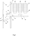
- the vending machine for dispensing packaged products comprises a housing 50 having a front outer wall 51 where one or more access openings 52 are formed. Each access opening 52 gives access to a collection zone 7 from which a user can take a packaged product 40 once it has been dispensed by a dispensing mechanism 22 located inside the housing 50.
- An access door 6 is manually operable to open and close the access opening 52.
- an actuator is configured and arranged to automatically open and close access door 6 when a packaged product 40 is detected in the collection zone 7 by a sensor.
- the front outer wall 51 of the vending machine housing 50 further comprises an input unit 53 for enabling the user to select the kind of packaged product 40 to be dispensed and a Point-Of-Sale terminal 54 for enabling the user to pay the selected packaged product 40.
- an insulated chamber 16 which houses therein a store structure 15 configured for storing one or several vertical stacks of gravity dischargeable packaged products 40, the corresponding dispensing mechanism 22 which is configured for supporting the stacks of packaged products 40 and for dispensing the lowermost packaged product 40 of a selected one of the stacks, and a conveyor belt 10 located below the dispensing mechanism 22 to receive the dispensed packaged products 40.
- the conveyor belt 10 is driven by a conveyor actuator 21 (shown in Fig. 3 ) for conveying the dispensed lowermost product 40 to a location outside the insulated chamber 16.
- the insulated chamber 16 is an insulated cooling chamber configured to keep the packaged products 40 below a predetermined temperature.
- the insulated chamber 16 is an insulated heating chamber configured to keep the packaged products 40 above a predetermined temperature.
- the housing 50 comprises a first insulating chamber 16 being an insulated heating chamber as previously described, and a second insulating chamber 16 being an insulated cooling chamber, as previously described.
- Such kind of arrangements are especially useful for dispensing packaged food products, as food products typically need to be stored in a cool or warm environment. However, such arrangements are also suitable for dispensing other types of packaged products, for example, medicines.
- the insulated chamber 16 comprises an insulating inner wall 2 parallel to and spaced apart from the front outer wall 51.
- the collection zone 7 of this exemplary embodiment is provided by a tray 20 arranged in a space between the insulating inner wall 2 and the front outer wall 51.
- the insulating inner wall 2 has an insulated door 4 adjacent to one end of the conveyor belt 10.
- the insulated door 4 is movable, for example by pivoting about a hinge 19, between a closed position and an open position.
- a door actuator (not shown) is operatively arranged to open and close the insulated door 4.
- the insulated door 4 has a passage opening with a downwards and outwards inclined bottom edge that forms an intermediate chute 18.
- the tray 20 in the collection zone 7 extends from the intermediate chute 18 to slightly below the access opening 52 in the front outer wall 51 of the housing 50 and is preferably also inclined downwards and outwards.
- a control unit of the machine sends a control signal to the dispensing mechanism 22 to drop the lowermost packaged product 40 of the corresponding stack while retaining the remaining packaged products 40 in the stack. So, the dropped packaged product 40 falls by gravity on the conveyor belt 10.
- the control unit sends a control signal to the door actuator to open the insulated door 4 and to the conveyor actuator 21 so that the conveyor belt 10 conveys the packaged product 40 outside the insulated chamber 16 through the intermediate chute 18 and to the tray 20 in the collection zone 7.
- the user can then take the dispensed packaged product 40 accessing the collection zone 7 through the corresponding access opening 52 in the front outer wall 51 of the housing 50.
- the conveyor actuator 21 of the conveyor belt 10 can be activated by the same control signal that activates the dispensing mechanism 22.
- the control unit sends a control signal to the door actuator to close the insulated door 4 and to the conveyor actuator 21 to stop the conveyor belt 10 when no packaged product 40 is sensed on the conveyor belt 10.
- the conveyor belt 10 is replaced by a dispensing chute inclined downwards to the insulated door 4, or directly to the access opening 52 if no insulated chamber is provided, with an equivalent result since the dispensed packaged product 40 slips down the dispensing chute by gravity to the insulated door 4 or to the access opening 52 and thereby no conveyor actuator is needed.
- the store structure 15 may be configured to store a single stack of packaged products 40 (not shown) or an array of stacks of packaged products 40, as can be seen in Figs. 2 and 3 , and in Figs. 7 and 8 .
- the store structure 15 is configured to store three rows of stacks following a first direction ( Fig. 2 ) and two rows of stacks following a second direction ( Fig. 3 ), with the second direction being perpendicular to the first direction.
- Fig. 7 also shows an embodiment of a vending machine according to the present invention comprising three rows of stacks following a first direction and two rows of stacks following a second direction perpendicular to said first direction.
- the number of rows in either direction may be varied according to the dimensions of the packaged products 40 to be stored and/or to the dimensions of the housing 50.
- different kinds of packaged products 40 can be dispensed provided that the packaged products 40 in each stack are of the same kind and have the same dimensions. However, different kinds of packaged products 40 can also have different dimensions provided that they have opposed edge holding portions 41. In this case, the dispensing mechanism 22 of each stack will be adapted to the dimensions of the packaged products 40 in that stack.
- the dispensing mechanism 22 of the first exemplary embodiment comprises two retention units 11 arranged on opposite sides of each vertical stack of packaged products 40.
- Each retention unit 11 comprises a support body 30 fixed to a machine frame (not shown), a movable element 31 and a dispensing actuator 32 configured and arranged for moving the movable element 31 between a retention position and a dispensing position.
- the movable elements 31 of the corresponding two retention units 11 interfere with the two opposed edge holding portions 41 of the lowermost packaged product 40.1 of the stack so that this lowermost packaged product 40.1 is retained and the remaining packaged products 40 of the stack rest on one another and on the lowermost packaged product 40.
- the movable elements 31 are returned back to the retention position quickly enough to interfere with the opposed edge holding portions 41 of the next packaged product 40.2 of the stack so that only one packaged product 40.1, namely the lowermost one, is delivered.
- control unit of the vending machine is configured to send control signals to the dispensing actuator 32 so as to drive the movable elements 31 of the retention units 11 from the retention position ( Fig. 4 ) to the dispensing position ( Fig. 5 ) and to quickly return the movable elements 31 of the retention units 11 back to the retention position from the dispensing position ( Fig. 6 ) in order to interfere with the edge holding portions 41 of the next packaged product 40.2 in the stack.
- the time interval lapsed from the dispensing position back to the retention position of the movable elements 31 is selected to be less that the time spent for the next packaged product 40.2 in the stack to fall by gravity a distance equivalent to its own height, so that the next packaged product 40.2 in the stack is retained then in the lowermost position by the movable elements 31.
- the time interval lapsed from the dispensing position back to the retention position of the movable elements 31 may be regulated in order to enable the delivery of more than one packaged product 40 of the stack in a single dispensing operation.
- the movable elements 31 move from the retention position to the dispensing position following a backwards movement along a linear path and move from the dispensing position to the retention position following an advance movement along the linear path.
- the path followed by the movable elements 31 is perpendicular to a longitudinal axis defined by the stack of gravity lowered packaged products.
- said path may be inclined in respect to said longitudinal axis of the stack.
- said longitudinal axis defined by the stack of gravity lowered packaged products is vertical.
- the linear path is defined by the U-shaped guide members 33.
- Fig. 7 shows the store structure 15 for storing at least one vertical stack of gravity lowered packaged products 40 and the dispensing mechanism 22 for supporting a corresponding stack of gravity lowered packaged products 40 and dispensing the lowermost packaged product 40 of said stack, of a second exemplary embodiment of a vending machine according to the present invention.
- the store structure 15 of this second exemplary embodiment is configured to store three rows of stacks following a first direction and two rows of stacks following a second direction perpendicular to said first direction.
- the store structure 15 of this exemplary embodiment comprises four guides 63 for each stack, each guide 63 having a substantially cylindrical shape.
- the guides 63 can have a different shape, for example, can be of a substantially quadrangular prismatic shape, planar, etc.
- Other embodiments can comprise a different number of guides 63 for each stack, although at least one guide for each side of the packaged product 40 is preferred.
- Each guide 63 can be easily attached or removed from the store structure 15 in order to, for example, ease maintenance operations.
- the dispensing mechanism 22 of this second exemplary embodiment comprises two retention units 11 arranged on opposite side of each vertical stack. Similar to the exemplary embodiments previously shown, each retention unit 11 comprises a support body 30, a movable element 31 and a dispense actuator 32 for moving the movable element from a retention position to a dispensing position and vice versa.
- the support body 30 is common for each row of retention units 11. However, in other embodiment each retention unit 11 could have its own support body 30.
- the support body 30 shown comprises a frontal wall 35 for guiding the at least one edge holding portion 41 of the packaged product 40 and further comprises a sloped wall 38 adjacent to the frontal wall 35. Said sloped wall 38 is optional and is configured to guide the packaged products 40 to the frontal wall 35.
- Said frontal wall 35 comprises at least one opening 60 for the passage of at least part of the movable element 31, so that said movable element 31 can move from its retention position to its dispensing position, and vice versa.
- Movable elements 31 are driven by associated dispensing actuators 32 that, in this exemplary embodiment, are operatively connected to the corresponding movable element 31 by a shank 36.
- the support structure 15 shown further comprises two lateral guides 64 arranged on the lowermost part of the support structure 15 to further guide the major lateral sides of the lowermost packaged product 40 of the stack so that the retention units 11 can effectively support the stack of packaged products 40 and dispense the lowermost packaged product 40 of said stack.
- Said lateral guides 64 are optional and at least one guide 64 for each lateral major side of the stack would suffice.
- the frontal wall 35 guides the lateral minor lateral sides of the stack of packaged products 40.
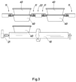
- Figs. 8 and 9 show a detail perspective view of the dispensing mechanism 22 of the exemplary embodiment of a vending machine shown in FIG. 7 .
- the at least one opening 60 for the passage of at least part of the movable element 31 is defined by three separate openings 60A, 60B, 60C adjacent one another and arranged in a linear manner.
- the openings 60A, 60B, 60C are separated by corresponding intermediate regions 61, which, in this exemplary embodiment, interfere with the advance movement of the movable element 31, acting as a stop defining the retention position of the corresponding movable element 31.
- the at least one opening 60 besides allowing passage of at least part of the movable element 31 so that it can reach its retention position wherein it interferes with an edge holding portion 41 of the lowermost packaged product 40 of the stack, can also act as a support of said movable element 31, preventing the movable element 31 and the shank 36 of the associated dispensing actuator 32 to flex excessively, as the movable element 31 and/or the shank 36 can rest on the edge of the at least one opening 60.
- An excessive flexion of the movable element 31 and/or of the shank 36 of the dispensing actuator 32 should be avoided as it could break them or, at least, reduce its lifespan. This also applies when said at least one opening 60 is divided into two or more separate openings 60A, 60B, 60C.
- the movable element 31 comprises one notch or recess 39 for each intermediate region 61 of the corresponding opening 60, thereby allowing passage of at least part of the movable element 31 through the openings 60A, 60B, 60C so that the movable element 31 can reach its retaining position.
- Said intermediate region 61 act as a stop against the corresponding recess 39 interfering with the advance movement of the movable element 31, thereby limiting the travel of the movable element 31 and defining its retention position.
- Said recesses 39 do not affect the retention ability of the movable element 31.
- Said intermediate region 61 does not affect the backwards movement of the movable element 31 from the retention position to the dispensing position.
- the central opening 60B comprises a substantially cylindrical indentation 62 for the passage of the shank 36 of the dispensing actuator 32.
- said indentation 62 may have a different shape or may not be present, depending, among others, on the shape of the shank 36 and the attachment of the movable element 31 to the corresponding shank 36.
- Fig. 8 shows in great detail the lateral guides 64, as well as the fastening of the guides 63 to the chassis of the store structure 15.
- Fig. 10 shows a detail perspective view of the store structure 15 and the dispensing mechanism 22 of a third exemplary embodiment of a vending machine according to the present invention.
- the at least one opening 60 for the passage of at least part of the movable element 31 is defined by four separate openings 60A, 60B, 60C, 60D adjacent one another and arranged in a linear manner and separated by three intermediate regions 61.
- the movable elements 31 of the third exemplary embodiment comprises two protrusions 38, one at each longitudinal end thereof, that act as a guide of the movable element 31 when it moves through the opening 60, in this case, openings 60A, 60B, 60C, 60D.
- the protrusions 38 ensure that the movable element 31 is maintained aligned with the corresponding opening 60 and are shaped so that they do not interfere with the dispensing and retention capability of the movable element 31.
- two protrusions 38 are preferred, one at each longitudinal end of the movable element 31, a single protrusion 38 could also suffice.
- the protrusions 38 extend towards the corresponding stack of gravity lowered packaged products 40.
- the central openings 60B, 60C comprise a substantially cylindrical indentation 62 for avoiding interference of the shank 36 of the dispensing actuator 32 with the frontal wall 35.
- both the central openings 60B, 60C comprise the indentation 62, although in this case only one would suffice as the dispensing actuator 62 comprises a single shank 36, the same frontal wall 35 can be used at either side of the stack of gravity lowered packaged products 40 (see Fig. 11 for better understanding).
- the intermediate regions 61 interfere with the distal surface 390 of the corresponding recess 39 when the movable element 31 advances towards the stack of gravity lowered packaged products 40, thereby defining the retention position of the movable element 31.
- the movable elements 31 move from the retention position to the dispensing position following a backwards movement along a linear path that is perpendicular to the longitudinal axis defined by the corresponding stack of gravity lowered packaged products 40; and move from the dispensing position to the retention position following an advance movement along said linear path.
- the openings 60A, 60B, 60C, 60D aid in guiding the movement of the movable element 31.
- This arrangement is clearly shown in Fig. 11 that shows a perspective view of movable elements and corresponding dispensing actuators arranged between opposing stacks of gravity lowered packaged products 40 of the exemplary embodiment shown in Fig. 10 .
- each movable element 31 comprises three notches or recesses 39, one for each intermediate region 61 shown in Fig. 10 .
- the recesses 39 closer to the longitudinal ends of the movable element 31 are wider than the central recess 39, as the central intermediate region 61 is narrower than the other two.
- all recesses 39 and intermediate regions 61 can have the same dimensions or have the recesses 39 having different dimensions arranged in a different manner, for example, the central recess 39, and corresponding intermediate region 61, being wider than the ones closer to the longitudinal ends of the movable element 31.
- Each recess 39 of this exemplary embodiment comprises a distal surface 390 and lateral surfaces 391 extending towards said distal surface 390 in a convergent manner, that is to say, the recess 39 narrows towards the distal surface 390.
- This shape prevents the lateral surfaces 391 to get stuck with the intermediate regions 61 which could prevent the movable element 31 from reaching its retention position.
- the movable elements 31 of this exemplary embodiment comprise a protrusion extending towards the corresponding stack of gravity lowered packaged products 40 that guide the movable element 31 when moving in a backwards or advance direction through the corresponding opening 60, 60A, 60D.
- the movable elements 31 shown comprise two connection orifices 37 for connecting the shank 36 of the dispensing actuator 32 to the movable element 31.
- the movable elements 31 shown comprise two connection orifices 37 as this makes them reversible and can be used in either side of the stack of gravity lowered packaged products 40, thus reducing the number of different pieces of the vending machine.
- the movable element 31 comprises a recess that allows the movable element 31 to be arranged closer to the dispensing actuator 32 and, thus, provide a more compact arrangement of the store structure 15 and of the vending machine.
- the different elements or parts of the movable elements 31 shown in Fig. 11 are symmetrical with respect to a transversal axis of symmetry.
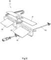
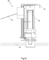
- Figs. 12 and 13 show a perspective and a side view, respectively, of a lowering mechanism of the third exemplary embodiment of a vending machine according to the present invention shown in Figs. 10 and 11 .
- Certain packaged products 40 can be damaged if they fall from the stack of gravity lowered packaged products 40 from a certain height. This depends on the heigh from the lowermost packaged product 40 of the stack and on the type of product stored therein. However, there are other reasons to avoid a fall from a certain height of a dispensed packaged product 40, as for example, a reduction of the noise produced by the impact. In conclusion, there are a number of reasons to avoid a fall of the dispensed product 40 from a certain height.
- embodiments of the vending machine according to the present invention can comprise a lowering mechanism 70 for receiving the dispensed packaged product 40 and lowering it to a transport element for conveying said packaged product 40 to the collection 7, or directly to the collection zone 7 (see, for example, Fig. 1 ).
- the lower mechanism 70 shown in Figs. 12 and 13 comprises a movable platform 71 that is configured to be raised to a receiving position, in which it receives the dispensed packaged product 40, and to be lowered to a discharging position, in which the dispensed packaged product 40 is discharged to the transport element or directly to the collection zone 7.
- the movable platform 71 is depicted in its receiving position, whereas in Fig. 13 said movable platform 71 is depicted in its discharging position.
- the lowering mechanism 70 comprises a driving unit 72 that, in the exemplary embodiment shown, can slide along a guide 73.
- the optional discharging ramps 74 depicted in Figs. 12 and 13 aid in dampening the fall of the packaged product 40 (not shown) from the movable platform to the transport element or to the collection zone 7. Moreover, said discharging ramps 74 also guide the fall of the packaged product 40 from the movable platform 71 to the transport element or to the collection zone 7.
- the lowering mechanism 70 comprises two discharging ramps 74, in other embodiments the lowering mechanism can comprise a different number of discharging ramps 74, for example, one, three, etc. Said discharging ramp 74 is optional and other embodiments may lack such element.
- the driving unit 72 moves along the guide 73 until it reaches a stop that interferes with the packaged product 40 located on the movable platform 71, so that the packaged product 40 is pushed out of the movable platform 71 and falls to the collection zone 7 or the transport element guided by the discharge ramps 74.
- the movable platform can be configured to tilt, so that by tilting the movable platform the packaged product 40 falls from it.
- Other arrangements for discharging the packaged product 40 from the movable platform are also possible within the scope of the present invention.
- the dispensing actuator 32 in the exemplary embodiments shown above is a magnetic linear actuator which is able to impart a quick movement to the movable element 31.
- Examples of useful magnetic linear actuators are a bistable linear moving magnet and a spring return actuator comprising, for example, an electromagnet arranged to perform the movement of the movable element from the retaining position to the dispensing position in cooperation with a spring arranged to return the movable element back to the retaining position.
- the present invention provides a method for dispensing a packaged product 40 from a vending machine comprising the essential features of the vending machine described above.
- the method comprises the following steps:
- the method then comprises resting the opposed edge holding portions 41 of the following lowermost packaged product 40 of the stack on the movable elements 31 of the retention units 11 which are back in the retention position.
- Also envisaged with the method is the optional step of conveying the dispensed packaged product 40 either with a dispensing chute or with a conveyor belt 10 to a collection zone 7 or to an intermediate location.
- the method optionally comprises the step of sensing the presence of the dispensed packaged product 40 on the dispensing chute or on the conveyor belt 10 and open an insulated door 4 of an insulated chamber 16 which houses therein the store structure 15, and a further step of closing said insulated door 4 once the dispensed packaged product 40 is no longer sensed on the dispensing chute or on the conveyor belt 10.
- the method further comprises the step of opening an access door 6 closing an access opening 52 through which the collection zone 7 is accessible from the outside once a packaged product 40 is sensed in the collection zone 7.
- vending machines for dispensing packaged products as well as the methods for dispensing a packaged product, previously described are specially envisaged for dispensing packaged food products, but any other suitable packaged product could also be dispensed.
- the vending machines and the method object of the present invention can also dispense non packaged products by previously placing said non packaged product in a package 40 having opposed edge holding portions 41 as the ones shown in Fig. 7 , for example.
Landscapes
- Physics & Mathematics (AREA)
- General Physics & Mathematics (AREA)
- Vending Machines For Individual Products (AREA)
Claims (15)
- Verkaufsautomat zum Ausgeben von verpackten Produkten, wobei jedes der verpackten Produkte (40) gegenüberliegende Kantenhalteabschnitte (41) aufweist, wobei der Verkaufsautomat ein Gehäuse (50) aufweist, das Folgendes umfasst:- eine Sammelzone (7) für ein ausgegebenes verpacktes Produkt (40);- eine Speicherstruktur (15) zum Speichern mindestens eines vertikalen Stapels von durch Schwerkraft abgesenkten verpackten Produkten (40), wobei jeder vertikale Stapel von durch Schwerkraft abgesenkten verpackten Produkten (40) eine Längsachse definiert;- einen Ausgabemechanismus (22) zum Tragen eines entsprechenden Stapels von durch Schwerkraft abgesenkten verpackten Produkten (40) und zum Ausgeben des untersten verpackten Produkts (40) des Stapels;wobei der Ausgabemechanismus (22) mindestens zwei Rückhalteeinheiten (11) umfasst, die an gegenüberliegenden Seiten des vertikalen Stapels angeordnet sind, wobei jede Rückhalteeinheit (11) eine Rückhalteposition zum Eingreifen in einen Kantenhalteabschnitt (41) des untersten verpackten Produkts (40) des Stapels und eine Ausgabeposition zum Freigeben des Kantenhalteabschnitts (41) des untersten verpackten Produkts (40) aufweist;wobei der Verkaufsautomat ferner eine Steuereinheit umfasst, die dazu konfiguriert ist, die Rückhalteeinheiten (11) aus der Rückhalteposition in die Ausgabeposition zu fahren und die Rückhalteeinheiten (11) aus der Ausgabeposition in die Rückhalteposition zurückzuführen, sobald mindestens das unterste verpackte Produkt (40) des Stapels durch Schwerkraft gefallen ist;wobei jede Rückhalteeinheit (11) einen Tragkörper (30), ein bewegliches Element (31) und ein Ausgabestellglied (32) umfasst, um das bewegliche Element (31) von einer Rückhalteposition in eine Ausgabeposition und umgekehrt zu bewegen;dadurch gekennzeichnet, dass jedes bewegliche Element (31) dazu konfiguriert ist, sich von der Rückhalteposition in die Ausgabeposition im Zuge einer Rückwärtsbewegung entlang eines linearen Pfades zu bewegen, und sich von der Ausgabeposition in die Rückhalteposition im Zuge einer Vorschubbewegung entlang des linearen Pfades zu bewegen.
- Verkaufsautomat nach Anspruch 1, dadurch gekennzeichnet, dass der lineare Pfad senkrecht zu der Längsachse verläuft, die durch den entsprechenden Stapel von durch Schwerkraft abgesenkten verpackten Produkten (40) definiert ist.
- Verkaufsautomat nach Anspruch 1 oder 2, dadurch gekennzeichnet, dass der Tragkörper (30) eine Stirnwand (35) zum Führen des mindestens einen Kantenhalteabschnitts (41) des verpackten Produkts (40) umfasst.
- Verkaufsautomat nach Anspruch 3, dadurch gekennzeichnet, dass die Stirnwand (35) mindestens eine Öffnung (60) für den Durchgang von mindestens einem Teil des beweglichen Elements (31) umfasst.
- Verkaufsautomat nach Anspruch 4, dadurch gekennzeichnet, dass die Stirnwand (35) zwei oder mehr Öffnungen (60A, 60B, 60C, 60D) für den Durchgang von zwei oder mehr Teilen (31A, 31B, 31C) des entsprechenden beweglichen Elements (31) umfasst.
- Verkaufsautomat nach Anspruch 5, dadurch gekennzeichnet, dass benachbarte Öffnungen (60A, 60B, 60C, 60D) durch einen Zwischenbereich (61) getrennt sind, wobei jeder Zwischenbereich (61) in die Vorschubbewegung des beweglichen Elements (31) eingreift, um dessen Rückhalteposition zu definieren.
- Verkaufsautomat nach Anspruch 6, dadurch gekennzeichnet, dass das bewegliche Element (31) eine Aussparung (39) für jeden Zwischenbereich (61) umfasst, wobei jede Aussparung eine distale Oberfläche (390) zum Eingreifen in den entsprechenden Zwischenbereich (61) aufweist, die als ein Anschlag des beweglichen Elements (31) wirkt und dessen Rückhalteposition definiert.
- Verkaufsautomat nach Anspruch 7, dadurch gekennzeichnet, dass die Aussparung (39) zwei Seitenoberflächen (391) aufweist, die sich konvergierend in Richtung der distalen Oberfläche (390) erstrecken.
- Verkaufsautomat nach einem der Ansprüche 6 bis 8, dadurch gekennzeichnet, dass der Zwischenbereich (61) Teil der Stirnwand (35) ist.
- Verkaufsautomat nach einem der vorhergehenden Ansprüche, dadurch gekennzeichnet, dass das bewegliche Element (31) an seinen gegenüberliegenden Längsenden einen Vorsprung (38) umfasst, um das bewegliche Element (31) durch die entsprechende Öffnung (60, 60A, 60B, 60C, 60D) zu führen.
- Verkaufsautomat nach einem der vorhergehenden Ansprüche, dadurch gekennzeichnet, dass er ferner einen Absenkmechanismus (70) zum Aufnehmen des ausgegebenen verpackten Produkts (40) und zum Absenken desselben auf ein Transportelement, um das ausgegebene verpackte Produkt (40) zur Sammelzone (7) zu befördern, oder zur Sammelzone (7) umfasst.
- Verkaufsautomat nach Anspruch 11, dadurch gekennzeichnet, dass der Absenkmechanismus (70) eine bewegliche Plattform (71) umfasst, die dazu konfiguriert ist, sich in eine Aufnahmeposition zu heben, in der sie das ausgegebene verpackte Produkt (40) aufnimmt, und sich in eine Abgabeposition abzusenken, in der das ausgegebene verpackte Produkt (40) auf das Transportelement oder in die Sammelzone (7) abgegeben wird.
- Verfahren zum Ausgeben eines verpackten Produkts (40) aus einem Verkaufsautomaten, umfassend die folgenden Schritte:- Bereitstellen eines Verkaufsautomaten nach einem der Ansprüche 1 bis 12;- Laden mindestens eines verpackten Produkts (40), das gegenüberliegende Kantenhalteabschnitte (41) aufweist, auf eine Speicherstruktur (15) zum Speichern mindestens eines Stapels von durch Schwerkraft abgesenkten verpackten Produkten (40), so dass die gegenüberliegenden Kantenhalteabschnitte (41) des verpackten Produkts (40) auf entsprechenden beweglichen Elementen (31) von Rückhalteeinheiten (11) aufliegen, die in einer Rückhalteposition angeordnet sind;- Bewegen der beweglichen Elemente (31) der Rückhalteeinheiten (11) aus der Rückhalteposition in eine Ausgabeposition, in der die gegenüberliegenden Kantenhalteabschnitte (41) des verpackten Produkts (40) nicht mehr auf den Rückhalteeinheiten (11) aufliegen, im Zuge einer Rückwärtsbewegung entlang eines linearen Pfades;- Zulassen, dass mindestens das unterste verpackte Produkt (40) durch die Schwerkraft an den beweglichen Elementen (31) der Rückhalteeinheiten (11) vorbeifällt;- Bewegen der beweglichen Elemente (31) der Rückhalteeinheiten (11) von der Ausgabeposition in die Rückhalteposition im Zuge einer Vorschubbewegung entlang des linearen Pfades;- gegebenenfalls Auflegen der gegenüberliegenden Kantenhalteabschnitte (41) des folgenden untersten verpackten Produkts (40) des Stapels auf die Rückhalteeinheiten (11) in der Rückhalteposition.
- Verfahren nach Anspruch 13, ferner umfassend den Schritt des Aufnehmens des ausgegebenen verpackten Produkts (40) mit einem Absenkmechanismus (70) und des Absenkens desselben auf ein Transportelement, um das ausgegebene verpackte Produkt (40) zur Sammelzone (7) zu befördern, oder zu einer Sammelzone (7).
- Verfahren nach Anspruch 14, wobei der Schritt des Aufnehmens des ausgegebenen verpackten Produkts (40) und des Absenkens desselben auf das Transportelement oder zur Sammelzone (7) die folgenden Schritte umfasst:- Anheben einer beweglichen Plattform (71) in eine Aufnahmeposition;- Aufnehmen des ausgegebenen verpackten Produkts (40) auf der beweglichen Plattform (71);- Absenken der beweglichen Plattform (71) mit dem ausgegebenen verpackten Produkt (40) in eine Abgabeposition; und- Abgeben des ausgegebenen verpackten Produkts (40) an das Transportelement oder an die Sammelzone (7).
Applications Claiming Priority (1)
| Application Number | Priority Date | Filing Date | Title |
|---|---|---|---|
| EP22382468.1A EP4280183A1 (de) | 2022-05-16 | 2022-05-16 | Verkaufsautomat zur ausgabe von verpackten produkten und verfahren zur ausgabe eines verpackten produkts aus einem verkaufsautomat |
Publications (3)
| Publication Number | Publication Date |
|---|---|
| EP4280184A1 EP4280184A1 (de) | 2023-11-22 |
| EP4280184B1 true EP4280184B1 (de) | 2024-10-30 |
| EP4280184C0 EP4280184C0 (de) | 2024-10-30 |
Family
ID=81941089
Family Applications (2)
| Application Number | Title | Priority Date | Filing Date |
|---|---|---|---|
| EP22382468.1A Withdrawn EP4280183A1 (de) | 2022-05-16 | 2022-05-16 | Verkaufsautomat zur ausgabe von verpackten produkten und verfahren zur ausgabe eines verpackten produkts aus einem verkaufsautomat |
| EP23173604.2A Active EP4280184B1 (de) | 2022-05-16 | 2023-05-16 | Verkaufsautomat zur ausgabe von verpackten produkten und verfahren zur ausgabe eines verpackten produkts aus einem verkaufsautomaten |
Family Applications Before (1)
| Application Number | Title | Priority Date | Filing Date |
|---|---|---|---|
| EP22382468.1A Withdrawn EP4280183A1 (de) | 2022-05-16 | 2022-05-16 | Verkaufsautomat zur ausgabe von verpackten produkten und verfahren zur ausgabe eines verpackten produkts aus einem verkaufsautomat |
Country Status (2)
| Country | Link |
|---|---|
| EP (2) | EP4280183A1 (de) |
| ES (1) | ES3007989T3 (de) |
Family Cites Families (7)
| Publication number | Priority date | Publication date | Assignee | Title |
|---|---|---|---|---|
| US3000538A (en) | 1956-08-06 | 1961-09-19 | Haller Jacob | Food-vending machine |
| US3137410A (en) | 1962-07-26 | 1964-06-16 | Rank Precision Ind Ltd | Coin-operated vending machines |
| US3651752A (en) | 1970-01-26 | 1972-03-28 | Nat Electro Cook Corp | Method and apparatus for heating and dispensing individually packaged food products |
| GB8515235D0 (en) * | 1985-06-15 | 1985-07-17 | Sankey Vending Ltd | Article release apparatus |
| US5147068A (en) * | 1991-01-16 | 1992-09-15 | Wright Food Systems, Inc. | Automated food vending system |
| US5503300A (en) | 1994-04-21 | 1996-04-02 | Krh Thermal Systems | Vending machine including refrigeration and oven compartments |
| IT1287420B1 (it) * | 1996-04-12 | 1998-08-06 | Giuseppe Biffarella | Distributore automatico di cibi caldi in vaschetta |
-
2022
- 2022-05-16 EP EP22382468.1A patent/EP4280183A1/de not_active Withdrawn
-
2023
- 2023-05-16 EP EP23173604.2A patent/EP4280184B1/de active Active
- 2023-05-16 ES ES23173604T patent/ES3007989T3/es active Active
Also Published As
| Publication number | Publication date |
|---|---|
| EP4280184A1 (de) | 2023-11-22 |
| EP4280183A1 (de) | 2023-11-22 |
| EP4280184C0 (de) | 2024-10-30 |
| ES3007989T3 (en) | 2025-03-21 |
Similar Documents
| Publication | Publication Date | Title |
|---|---|---|
| US4542834A (en) | Dispensing mechanism for vending machines | |
| EP1886283B1 (de) | Abgabelade für einen verkaufsautomaten | |
| US4574980A (en) | Vending machine dispensing mechanism | |
| EP0256882A2 (de) | Verkaufsbehälter | |
| KR101364037B1 (ko) | 개선된 상품 디스펜서 및 이를 구비한 자동 상품 공급기 | |
| EP1551737A1 (de) | Artikelspeichermagazin für eine artikelhandhabungsvorrichtung | |
| EP2070062A1 (de) | Lebensmittelautomat und verfahren zur automatischen zuführung und erwärmung von lebensmittelpackungen | |
| US4565300A (en) | Dispensing mechanism for vending machines or the like | |
| WO1998015926A1 (en) | Vending machine | |
| KR20160055070A (ko) | 자동 판매기의 상품 반출 장치 | |
| US6431398B1 (en) | Dispensing mean for vending machine | |
| WO1991006076A1 (en) | Automatic vending machine | |
| EP4280184B1 (de) | Verkaufsautomat zur ausgabe von verpackten produkten und verfahren zur ausgabe eines verpackten produkts aus einem verkaufsautomaten | |
| JPH0394398A (ja) | 自動販売機 | |
| EP0875043B1 (de) | Münzausgabegerät | |
| US20220327884A1 (en) | First dispenser module, vending kit comprising said first dispenser module and method | |
| JP7252848B2 (ja) | 自動販売機、商品収容棚及び商品搬出装置 | |
| JP2559566B2 (ja) | 自動販売機の商品払出装置 | |
| US20030146238A1 (en) | Vending machine for dispensing cans & bottles with elevator assembly | |
| JP2566743B2 (ja) | 自動販売機の商品払出装置 | |
| JPH1055485A (ja) | ケースパック商品自動販売機 | |
| JP3489959B2 (ja) | 自動販売機の商品払出装置のばね取付構造 | |
| JP2662012B2 (ja) | 自動販売機の商品棚 | |
| JPH11175838A (ja) | 自動販売機 | |
| JPH08161625A (ja) | 自動販売機の商品収納室 |
Legal Events
| Date | Code | Title | Description |
|---|---|---|---|
| PUAI | Public reference made under article 153(3) epc to a published international application that has entered the european phase |
Free format text: ORIGINAL CODE: 0009012 |
|
| STAA | Information on the status of an ep patent application or granted ep patent |
Free format text: STATUS: THE APPLICATION HAS BEEN PUBLISHED |
|
| AK | Designated contracting states |
Kind code of ref document: A1 Designated state(s): AL AT BE BG CH CY CZ DE DK EE ES FI FR GB GR HR HU IE IS IT LI LT LU LV MC ME MK MT NL NO PL PT RO RS SE SI SK SM TR |
|
| STAA | Information on the status of an ep patent application or granted ep patent |
Free format text: STATUS: REQUEST FOR EXAMINATION WAS MADE |
|
| 17P | Request for examination filed |
Effective date: 20240426 |
|
| GRAP | Despatch of communication of intention to grant a patent |
Free format text: ORIGINAL CODE: EPIDOSNIGR1 |
|
| RBV | Designated contracting states (corrected) |
Designated state(s): AL AT BE BG CH CY CZ DE DK EE ES FI FR GB GR HR HU IE IS IT LI LT LU LV MC ME MK MT NL NO PL PT RO RS SE SI SK SM TR |
|
| STAA | Information on the status of an ep patent application or granted ep patent |
Free format text: STATUS: GRANT OF PATENT IS INTENDED |
|
| INTG | Intention to grant announced |
Effective date: 20240606 |
|
| GRAS | Grant fee paid |
Free format text: ORIGINAL CODE: EPIDOSNIGR3 |
|
| GRAA | (expected) grant |
Free format text: ORIGINAL CODE: 0009210 |
|
| STAA | Information on the status of an ep patent application or granted ep patent |
Free format text: STATUS: THE PATENT HAS BEEN GRANTED |
|
| AK | Designated contracting states |
Kind code of ref document: B1 Designated state(s): AL AT BE BG CH CY CZ DE DK EE ES FI FR GB GR HR HU IE IS IT LI LT LU LV MC ME MK MT NL NO PL PT RO RS SE SI SK SM TR |
|
| REG | Reference to a national code |
Ref country code: GB Ref legal event code: FG4D |
|
| REG | Reference to a national code |
Ref country code: CH Ref legal event code: EP |
|
| REG | Reference to a national code |
Ref country code: IE Ref legal event code: FG4D |
|
| REG | Reference to a national code |
Ref country code: DE Ref legal event code: R096 Ref document number: 602023000864 Country of ref document: DE |
|
| U01 | Request for unitary effect filed |
Effective date: 20241120 |
|
| U07 | Unitary effect registered |
Designated state(s): AT BE BG DE DK EE FI FR IT LT LU LV MT NL PT RO SE SI Effective date: 20241127 |
|
| REG | Reference to a national code |
Ref country code: ES Ref legal event code: FG2A Ref document number: 3007989 Country of ref document: ES Kind code of ref document: T3 Effective date: 20250321 |
|
| PG25 | Lapsed in a contracting state [announced via postgrant information from national office to epo] |
Ref country code: IS Free format text: LAPSE BECAUSE OF FAILURE TO SUBMIT A TRANSLATION OF THE DESCRIPTION OR TO PAY THE FEE WITHIN THE PRESCRIBED TIME-LIMIT Effective date: 20250228 Ref country code: HR Free format text: LAPSE BECAUSE OF FAILURE TO SUBMIT A TRANSLATION OF THE DESCRIPTION OR TO PAY THE FEE WITHIN THE PRESCRIBED TIME-LIMIT Effective date: 20241030 |
|
| PG25 | Lapsed in a contracting state [announced via postgrant information from national office to epo] |
Ref country code: NO Free format text: LAPSE BECAUSE OF FAILURE TO SUBMIT A TRANSLATION OF THE DESCRIPTION OR TO PAY THE FEE WITHIN THE PRESCRIBED TIME-LIMIT Effective date: 20250130 |
|
| PG25 | Lapsed in a contracting state [announced via postgrant information from national office to epo] |
Ref country code: GR Free format text: LAPSE BECAUSE OF FAILURE TO SUBMIT A TRANSLATION OF THE DESCRIPTION OR TO PAY THE FEE WITHIN THE PRESCRIBED TIME-LIMIT Effective date: 20250131 |
|
| PG25 | Lapsed in a contracting state [announced via postgrant information from national office to epo] |
Ref country code: PL Free format text: LAPSE BECAUSE OF FAILURE TO SUBMIT A TRANSLATION OF THE DESCRIPTION OR TO PAY THE FEE WITHIN THE PRESCRIBED TIME-LIMIT Effective date: 20241030 |
|
| PG25 | Lapsed in a contracting state [announced via postgrant information from national office to epo] |
Ref country code: RS Free format text: LAPSE BECAUSE OF FAILURE TO SUBMIT A TRANSLATION OF THE DESCRIPTION OR TO PAY THE FEE WITHIN THE PRESCRIBED TIME-LIMIT Effective date: 20250130 |
|
| U20 | Renewal fee for the european patent with unitary effect paid |
Year of fee payment: 3 Effective date: 20250529 |
|
| PG25 | Lapsed in a contracting state [announced via postgrant information from national office to epo] |
Ref country code: SM Free format text: LAPSE BECAUSE OF FAILURE TO SUBMIT A TRANSLATION OF THE DESCRIPTION OR TO PAY THE FEE WITHIN THE PRESCRIBED TIME-LIMIT Effective date: 20241030 |
|
| PGFP | Annual fee paid to national office [announced via postgrant information from national office to epo] |
Ref country code: ES Payment date: 20250612 Year of fee payment: 3 |
|
| PG25 | Lapsed in a contracting state [announced via postgrant information from national office to epo] |
Ref country code: SK Free format text: LAPSE BECAUSE OF FAILURE TO SUBMIT A TRANSLATION OF THE DESCRIPTION OR TO PAY THE FEE WITHIN THE PRESCRIBED TIME-LIMIT Effective date: 20241030 |
|
| PG25 | Lapsed in a contracting state [announced via postgrant information from national office to epo] |
Ref country code: CZ Free format text: LAPSE BECAUSE OF FAILURE TO SUBMIT A TRANSLATION OF THE DESCRIPTION OR TO PAY THE FEE WITHIN THE PRESCRIBED TIME-LIMIT Effective date: 20241030 |
|
| PLBE | No opposition filed within time limit |
Free format text: ORIGINAL CODE: 0009261 |
|
| STAA | Information on the status of an ep patent application or granted ep patent |
Free format text: STATUS: NO OPPOSITION FILED WITHIN TIME LIMIT |
|
| 26N | No opposition filed |
Effective date: 20250731 |
|
| PG25 | Lapsed in a contracting state [announced via postgrant information from national office to epo] |
Ref country code: MC Free format text: LAPSE BECAUSE OF FAILURE TO SUBMIT A TRANSLATION OF THE DESCRIPTION OR TO PAY THE FEE WITHIN THE PRESCRIBED TIME-LIMIT Effective date: 20241030 |