EP4280128A1 - Vorrichtung für informationssammlungs- und überwachungssystem - Google Patents
Vorrichtung für informationssammlungs- und überwachungssystem Download PDFInfo
- Publication number
- EP4280128A1 EP4280128A1 EP23173442.7A EP23173442A EP4280128A1 EP 4280128 A1 EP4280128 A1 EP 4280128A1 EP 23173442 A EP23173442 A EP 23173442A EP 4280128 A1 EP4280128 A1 EP 4280128A1
- Authority
- EP
- European Patent Office
- Prior art keywords
- information
- adjusting mechanism
- connecting hole
- mounting member
- truck
- Prior art date
- Legal status (The legal status is an assumption and is not a legal conclusion. Google has not performed a legal analysis and makes no representation as to the accuracy of the status listed.)
- Granted
Links
Images




Classifications
-
- G—PHYSICS
- G01—MEASURING; TESTING
- G01S—RADIO DIRECTION-FINDING; RADIO NAVIGATION; DETERMINING DISTANCE OR VELOCITY BY USE OF RADIO WAVES; LOCATING OR PRESENCE-DETECTING BY USE OF THE REFLECTION OR RERADIATION OF RADIO WAVES; ANALOGOUS ARRANGEMENTS USING OTHER WAVES
- G01S7/00—Details of systems according to groups G01S13/00, G01S15/00, G01S17/00
- G01S7/48—Details of systems according to groups G01S13/00, G01S15/00, G01S17/00 of systems according to group G01S17/00
- G01S7/481—Constructional features, e.g. arrangements of optical elements
-
- B—PERFORMING OPERATIONS; TRANSPORTING
- B66—HOISTING; LIFTING; HAULING
- B66F—HOISTING, LIFTING, HAULING OR PUSHING, NOT OTHERWISE PROVIDED FOR, e.g. DEVICES WHICH APPLY A LIFTING OR PUSHING FORCE DIRECTLY TO THE SURFACE OF A LOAD
- B66F9/00—Devices for lifting or lowering bulky or heavy goods for loading or unloading purposes
- B66F9/06—Devices for lifting or lowering bulky or heavy goods for loading or unloading purposes movable, with their loads, on wheels or the like, e.g. fork-lift trucks
- B66F9/063—Automatically guided
-
- G—PHYSICS
- G06—COMPUTING OR CALCULATING; COUNTING
- G06Q—INFORMATION AND COMMUNICATION TECHNOLOGY [ICT] SPECIALLY ADAPTED FOR ADMINISTRATIVE, COMMERCIAL, FINANCIAL, MANAGERIAL OR SUPERVISORY PURPOSES; SYSTEMS OR METHODS SPECIALLY ADAPTED FOR ADMINISTRATIVE, COMMERCIAL, FINANCIAL, MANAGERIAL OR SUPERVISORY PURPOSES, NOT OTHERWISE PROVIDED FOR
- G06Q10/00—Administration; Management
- G06Q10/02—Reservations, e.g. for tickets, services or events
-
- B—PERFORMING OPERATIONS; TRANSPORTING
- B66—HOISTING; LIFTING; HAULING
- B66F—HOISTING, LIFTING, HAULING OR PUSHING, NOT OTHERWISE PROVIDED FOR, e.g. DEVICES WHICH APPLY A LIFTING OR PUSHING FORCE DIRECTLY TO THE SURFACE OF A LOAD
- B66F9/00—Devices for lifting or lowering bulky or heavy goods for loading or unloading purposes
- B66F9/06—Devices for lifting or lowering bulky or heavy goods for loading or unloading purposes movable, with their loads, on wheels or the like, e.g. fork-lift trucks
- B66F9/075—Constructional features or details
- B66F9/0755—Position control; Position detectors
-
- G—PHYSICS
- G01—MEASURING; TESTING
- G01S—RADIO DIRECTION-FINDING; RADIO NAVIGATION; DETERMINING DISTANCE OR VELOCITY BY USE OF RADIO WAVES; LOCATING OR PRESENCE-DETECTING BY USE OF THE REFLECTION OR RERADIATION OF RADIO WAVES; ANALOGOUS ARRANGEMENTS USING OTHER WAVES
- G01S17/00—Systems using the reflection or reradiation of electromagnetic waves other than radio waves, e.g. lidar systems
- G01S17/86—Combinations of lidar systems with systems other than lidar, radar or sonar, e.g. with direction finders
-
- G—PHYSICS
- G01—MEASURING; TESTING
- G01S—RADIO DIRECTION-FINDING; RADIO NAVIGATION; DETERMINING DISTANCE OR VELOCITY BY USE OF RADIO WAVES; LOCATING OR PRESENCE-DETECTING BY USE OF THE REFLECTION OR RERADIATION OF RADIO WAVES; ANALOGOUS ARRANGEMENTS USING OTHER WAVES
- G01S17/00—Systems using the reflection or reradiation of electromagnetic waves other than radio waves, e.g. lidar systems
- G01S17/88—Lidar systems specially adapted for specific applications
-
- G—PHYSICS
- G06—COMPUTING OR CALCULATING; COUNTING
- G06Q—INFORMATION AND COMMUNICATION TECHNOLOGY [ICT] SPECIALLY ADAPTED FOR ADMINISTRATIVE, COMMERCIAL, FINANCIAL, MANAGERIAL OR SUPERVISORY PURPOSES; SYSTEMS OR METHODS SPECIALLY ADAPTED FOR ADMINISTRATIVE, COMMERCIAL, FINANCIAL, MANAGERIAL OR SUPERVISORY PURPOSES, NOT OTHERWISE PROVIDED FOR
- G06Q10/00—Administration; Management
- G06Q10/08—Logistics, e.g. warehousing, loading or distribution; Inventory or stock management
-
- H—ELECTRICITY
- H04—ELECTRIC COMMUNICATION TECHNIQUE
- H04N—PICTORIAL COMMUNICATION, e.g. TELEVISION
- H04N23/00—Cameras or camera modules comprising electronic image sensors; Control thereof
- H04N23/50—Constructional details
-
- H—ELECTRICITY
- H04—ELECTRIC COMMUNICATION TECHNIQUE
- H04N—PICTORIAL COMMUNICATION, e.g. TELEVISION
- H04N23/00—Cameras or camera modules comprising electronic image sensors; Control thereof
- H04N23/50—Constructional details
- H04N23/51—Housings
-
- H—ELECTRICITY
- H04—ELECTRIC COMMUNICATION TECHNIQUE
- H04N—PICTORIAL COMMUNICATION, e.g. TELEVISION
- H04N23/00—Cameras or camera modules comprising electronic image sensors; Control thereof
- H04N23/60—Control of cameras or camera modules
- H04N23/695—Control of camera direction for changing a field of view, e.g. pan, tilt or based on tracking of objects
-
- G—PHYSICS
- G06—COMPUTING OR CALCULATING; COUNTING
- G06N—COMPUTING ARRANGEMENTS BASED ON SPECIFIC COMPUTATIONAL MODELS
- G06N5/00—Computing arrangements using knowledge-based models
- G06N5/02—Knowledge representation; Symbolic representation
-
- G—PHYSICS
- G06—COMPUTING OR CALCULATING; COUNTING
- G06Q—INFORMATION AND COMMUNICATION TECHNOLOGY [ICT] SPECIALLY ADAPTED FOR ADMINISTRATIVE, COMMERCIAL, FINANCIAL, MANAGERIAL OR SUPERVISORY PURPOSES; SYSTEMS OR METHODS SPECIALLY ADAPTED FOR ADMINISTRATIVE, COMMERCIAL, FINANCIAL, MANAGERIAL OR SUPERVISORY PURPOSES, NOT OTHERWISE PROVIDED FOR
- G06Q2240/00—Transportation facility access, e.g. fares, tolls or parking
Definitions
- This disclosure relates to the field of cargo handling technology, and in particular to an apparatus for information collection and a monitoring system.
- the truck unloading is usually carried out by a manual forklift.
- uncontrollability of environment is increased due to human participation, such that awareness of the unmanned forklift to the environment and control of the manual equipment over the unmanned forklift are difficult to meet use requirements.
- unloading requirements of unmanned forklifts are reduced by restricting parking position of the truck and fixing a placement pose and a placement order of the cargo.
- inconvenience will be caused to an unloading process and an overall unloading efficiency will be affected.
- an apparatus for information collection includes an information collecting body and a first adjusting mechanism.
- the information collecting body is configured to collect information of a cargo and/or a truck.
- the information collecting body is mounted at the first adjusting mechanism.
- the first adjusting mechanism is configured to drive the information collecting body to rotate around an axis.
- a monitoring system is provided in embodiments of the present disclosure.
- the monitoring system includes the above apparatus for information collection.
- the information collecting body and the first adjusting mechanism are at least included.
- the information collecting body By disposing the information collecting body, the information of the cargo and/or the truck can be collected.
- the first adjusting mechanism By disposing the first adjusting mechanism, an angle of the information collecting body can be adjusted. Therefore, the apparatus for information collection can collect information of parking poses of the truck and poses of the cargo from multiple angles, such that the information collected by the apparatus for information collection is richer, and an unloading or loading mode of the unmanned forklift can be adjusted according to the information collected, thereby improving an unloading or loading efficiency.
- apparatus 10 for information collection information collecting body 100, camera 110, laser sensor 120, bracket 130, first adjusting mechanism 200, first mounting member 210, mounting groove 2101, first connecting hole 211, third projection 2111, third connecting hole 212, first projection 2121, bottom wall 210a, first side wall 210b, first end 213, second end 214, second mounting member 220, accommodating space 2201, second connecting hole 221, fourth projection 2211, fourth connecting hole 222, second projection 2221, second side wall 220a, third side wall 220b, first connecting member 230, second connecting member 240, second adjusting mechanism 300, third mounting member 310, guiding member 320, housing 400, first opening 401, second opening 402, accommodating cavity 403, connector 500, mounting seat 600, mounting baseplate 610, support member 620, mounting space 601, axis a , first direction z , second direction y , third direction x , reference plane R , intersection J of axis a and reference plane R , truck parking area P .
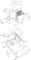
- FIG. 1 is a schematic structural diagram of an apparatus 10 for information collection in an implementation of the present disclosure
- FIG. 2 is a local exploded schematic structural diagram of an apparatus 10 for information collection in an implementation of the present disclosure
- FIG. 3 is a partial schematic structural diagram of an apparatus 10 for information collection in an implementation of the present disclosure.
- a housing 400 illustrated later is removed from FIG. 3 .
- an apparatus 10 for information collection is provided in embodiments of the present disclosure.
- the apparatus 10 for information collection includes an information collecting body 100 and a first adjusting mechanism 200.
- the information collecting body 100 is configured to collect information of a cargo and/or a truck, to realize identification and positioning of the cargo and/or the truck.
- the information collecting body 100 is mounted at the first adjusting mechanism 200.
- the first adjusting mechanism 200 is configured to drive the information collecting body 100 to rotate around an axis a .
- the apparatus 10 for information collection by disposing the information collecting body 100, the information of the cargo and/or the truck can be collected. By disposing the first adjusting mechanism 200, an angle of the information collecting body 100 can be adjusted. Therefore, the apparatus 10 for information collection can collect information of parking poses of the truck and poses of the cargo from multiple angles, such that the information collected by the apparatus 10 for information collection is richer, and an unloading or loading mode of the unmanned forklift can be adjusted according to the information collected, thereby improving an unloading or loading efficiency. In the embodiments, the apparatus 10 for information collection only has a function of rotating and adjusting an angle, but does not have a function of lifting and adjusting a height.
- the apparatus 10 for information collection in the embodiments of the present disclosure not only meets collection requirements for the information of the parking poses of the truck and the poses of the cargo, but also facilitates mounting and reduces usage costs.
- An apparatus 10 for information collection is provided in embodiments of the present disclosure, and the apparatus 10 for information collection is used in a process of cargo transfer.
- the process of cargo transfer includes unloading and loading of cargos.
- the apparatus 10 for information collection includes an information collecting body 100, a first adjusting mechanism 200, and a second adjusting mechanism 300.
- the information collecting body 100 is configured to collect information of a cargo and/or a truck to identify and locate the cargo and/or the truck.
- the information collecting body 100 is mounted at the first adjusting mechanism 200.
- the first adjusting mechanism 200 is configured to drive the information collecting body 100 to rotate around axis a .
- the first adjusting mechanism 200 is mounted at the second adjusting mechanism 300.
- the second adjusting mechanism 300 is configured to drive the first adjusting mechanism 200 to move back and forth in first direction z.
- Axis a (with reference to a left-right direction illustrated in FIG. 4 and FIG. 5 later) is perpendicular to first direction z (i.e., an up-down direction illustrated in FIG. 1 to FIG. 3 ).
- the second adjusting mechanism 300 is configured to drive the information collecting body 100 to move up and down in first direction z.
- the information collecting body 100 by disposing the information collecting body 100, the information of the cargo and/or the truck can be collected.
- the first adjusting mechanism 200 an angle of the information collecting body 100 can be adjusted.
- the second adjusting mechanism 300 By disposing the second adjusting mechanism 300, a position of the information collecting body 100 in the first direction can be adjusted. Therefore, by comprehensively adjusting the angle of the information collecting body 100 and the position of the information collecting body 100 in the first direction, information of different parking poses of the truck and different poses of the cargo can be collected, such that an unmanned forklift can adjust an unloading or loading mode according to the information collected, thereby improving an unloading or loading efficiency.
- the information of the cargo and/or the truck may include information such as appearance of the truck, coordinate information of the truck, appearance of the cargo and coordinate information of the cargo, etc.
- the truck carries the cargo.
- the truck includes a wing opening van, a flatbed truck, etc.
- the cargo includes a storage cage, a pallet and other carriers, and materials carried.
- Other information that needs to be collected, such as information of a truck parking area, can also be obtained according to actual usage requirements, which is not specifically limited in embodiments of the present disclosure.
- FIG. 4 is a schematic structural diagram illustrating a match between an information collecting body 100 and a first adjusting mechanism 200 from one perspective in an implementation of the present disclosure
- FIG. 5 is a schematic structural diagram illustrating a match between an information collecting body 100 and a first adjusting mechanism 200 from another perspective in an implementation of the present disclosure.
- FIG. 4 is a schematic structural diagram illustrating a match between an information collecting body 100 and a first adjusting mechanism 200 from one perspective in an implementation of the present disclosure
- FIG. 5 is a schematic structural diagram illustrating a match between an information collecting body 100 and a first adjusting mechanism 200 from another perspective in an implementation of the present disclosure.
- FIG. 4 is a schematic structural diagram illustrating a match between an information collecting body 100 and a first adjusting mechanism 200 from one perspective in an implementation of the present disclosure
- FIG. 5 is a schematic structural diagram illustrating a match between an information collecting body 100 and a first adjusting mechanism 200 from another perspective in an implementation of the present disclosure.
- FIG. 4 is a schematic structural diagram illustrating
- an angle of the information collecting body 100 can be adjusted.
- the first adjusting mechanism 200 can be driven to move back and forth in first direction z, and the first adjusting mechanism 200 can drive the information collecting body 100 to move back and forth in first direction z. Therefore, by comprehensively adjusting the angle of the information collecting body 100 and the position of the information collecting body 100 in first direction z, information of different parking poses of the truck and different poses of the cargo can be collected, such that an unmanned forklift can adjust a pickup mode according to the information collected, thereby improving an unloading efficiency.
- the pickup mode includes a pickup path, a fork inserting direction for pickup, a pickup order, etc., which can be adjusted according to actual usage situations and not be limited in embodiments of the present disclosure.
- FIG. 6 is a schematic structural diagram of a first adjusting mechanism 200 from one perspective in an implementation of the present disclosure
- FIG. 7 is a schematic structural diagram of a second mounting member 220 in an implementation of the present disclosure
- FIG. 8 is a schematic structural diagram of a first mounting member 210 in an implementation of the present disclosure
- FIG. 9 is a schematic structural diagram of a first adjusting mechanism 200 from another perspective in an implementation of the present disclosure.
- FIG. 6 is a schematic structural diagram of a first adjusting mechanism 200 from one perspective in an implementation of the present disclosure
- FIG. 7 is a schematic structural diagram of a second mounting member 220 in an implementation of the present disclosure
- FIG. 8 is a schematic structural diagram of a first mounting member 210 in an implementation of the present disclosure
- FIG. 9 is a schematic structural diagram of a first adjusting mechanism 200 from another perspective in an implementation of the present disclosure.
- FIG. 9 is a schematic structural diagram of a first adjusting mechanism 200 from another perspective in an implementation of the present disclosure.
- the first adjusting mechanism 200 includes a first mounting member 210 and a second mounting member 220.
- the information collecting body 100 is mounted at the first mounting member 210.
- the second mounting member 220 connects to the second adjusting mechanism 300.
- the first mounting member 210 has a first end 213 and a second end 214 opposite to the first end 213 in second direction y .
- the first end 213 is close to the second adjusting mechanism 300, and the second end 214 is away from the second adjusting mechanism 300.
- the first end 213 of the first mounting member 210 is rotatably connected with the second mounting member 220 around axis a .
- the second end 214 of the first mounting member 210 is detachably fixed to the second mounting member 220.
- Second direction y is perpendicular to axis a.
- first direction z, second direction y , and axis a are perpendicular to each other.
- Axis a is parallel to third direction x illustrated in schematic diagrams.
- the first adjusting mechanism 200 further includes a first connecting member 230.
- the first end 213 of the first mounting member 210 defines a first connecting hole 211
- the second mounting member 220 defines a second connecting hole 221 corresponding to the first connecting hole 211.
- the first connecting member 230 passes through the first connecting hole 211 and the second connecting hole 221.
- the first end 213 of the first mounting member 210 is rotatably connected with the second mounting member 220 through the first connecting member 230.
- the first connecting member 230, the first connecting hole 211, and the second connecting hole 221 form a rotating-shaft structure.
- the first connecting member 230 may have a rod-like structure.
- first connecting member 230 passes through the first connecting hole 211 and the second connecting hole 221, a longitudinal extension direction of the first connecting member 230 is parallel to axis a . Therefore, the first end 213 of the first mounting member 210 can be rotatably connected with the second mounting member 220 around axis a .
- FIG. 10 is a schematic diagram of a first projection 2121, a second projection 2221, a third projection 2111, and a fourth projection 2211 in an implementation of the present disclosure. For convenience of explanation, only parts related to embodiments of the present disclosure are illustrated.
- the first adjusting mechanism 200 further includes a second connecting member 240.
- the second end 214 of the first mounting member 210 defines a third connecting hole 212
- the second mounting member 220 defines a fourth connecting hole 222 corresponding to the third connecting hole 212.
- the second connecting member 240 detachably passes through the third connecting hole 212 and the fourth connecting hole 222.
- the second end 214 of the first mounting member 210 is detachably and fixedly connected with the second mounting member 220 through the second connecting member 240.
- the second connecting member 240 may have a bolt structure or other detachable and fixed structures, which is not specifically limited in embodiments of the present disclosure. As illustrated in FIG.
- an orthographic projection of the third connecting hole 212 on reference plane R is a first projection 2121
- an orthographic projection of the fourth connecting hole 222 on reference plane R is a second projection 2221
- the first projection 2121 partially overlaps the second projection 2221, where reference plane R is a plane perpendicular to axis a .
- the second projection 2221 is circular arc-shaped. More specifically, the first projection 2121 always falls within a range of the second projection 2221. For example, as illustrated in FIG.
- the first projection 2121 is circular
- the second projection 2221 is circular arc-shaped
- the first projection 2121 falls within the second projection 2221
- a center of the second projection 2221 is intersection J of axis a and reference plane R .
- the fourth connecting hole 222 extends in a circular arc shape centered at the center of the second connecting hole 221, which is convenient to match a rotation path of the first mounting member 210, and is convenient to adjust the first mounting member 210.
- the first mounting member 210 defines a mounting groove 2101 for mounting the information collecting body 100, which facilitates mounting of the information collecting body 100.
- the first mounting member 210 has a bottom wall 210a and two first side walls 210b.
- the two first side walls 210b are disposed at two opposite ends of the bottom wall 210a in third direction x.
- the bottom wall 210a and the two first side walls 210b cooperatively define the mounting groove 2101.
- the two first side walls 210b each can define the first connecting hole 211 and the third connecting hole 212.
- each first side wall 210b defines one first connecting hole 211 and one third connecting hole 212.
- the first mounting member 210 defines two first connecting holes 211 and two third connecting holes 212.
- the first mounting member 210 with other structural forms of the mounting groove 2101 may also be provided, which is not specifically limited in embodiments of the present disclosure.
- the second mounting member 220 includes a second side wall 220a and two third side walls 220b.
- the two third side walls 220b are disposed at two opposite ends of the second side wall 220a in third direction x.
- the two third side walls 220b each can be defined the second connecting hole 221 and the fourth connecting hole 222.
- each third side wall 220b defines one second connecting hole 221 and one fourth connecting hole 222.
- the second mounting member 220 defines two second connecting holes 221 and two fourth connecting holes 222.
- the two third side walls 220b of the second mounting member 220 are in one-to-one correspondence with the two first side walls 210b of the first mounting member 210.
- the second side wall 220a is disposed at one side of the mounting groove 2101 close to the second adjusting mechanism 300.
- the second side wall 220a and the two third side walls 220b cooperatively define an accommodating space 2201, and the first mounting member 210 is received in the accommodating space 2201. Therefore, as for the first adjusting mechanism 200, the first mounting member 210 matches the second mounting member 220 through two first connecting members 230 and two second connecting members 240.
- the second mounting member 220 in other structural forms matching the first mounting member 210 may also be disposed, which is not specifically limited in embodiments of the present disclosure.
- an orthographic projection of the third connecting hole 212 on reference plane R is a first projection 2121
- an orthographic projection of the fourth connecting hole 222 on reference plane R is a second projection 2221
- an orthographic projection of the first connecting hole 211 on reference plane R is a third projection 2111
- an orthographic projection of the second connecting hole 221 on reference plane R is a fourth projection 2211.
- Two first projections 2121 of the two third connecting holes 212 completely overlap with each other, and two second projections 2221 of the two fourth connecting holes 222 completely overlap with each other, two third projections 2111 of the two first connecting holes 211 completely overlap with each other, and two fourth projections 2211 of the two second connecting holes 221 completely overlap with each other, where reference plane R is a plane perpendicular to axis a . Therefore, the two first connecting members 230 can be ensured to extend in the same direction, where each of the two first connecting members 230 passes through the first side wall 210b and the third side wall 220b.
- the two second connecting members 240 can be ensured to extend in the same direction, where each of the two second connecting members 240 detachably passes through the first side wall 210b and the third side wall 220b, thereby ensuring that the first mounting member 210 smoothly rotates relative to the second mounting member 220.
- the second adjusting mechanism 300 includes a third mounting member 310 and a guiding member 320.
- the first adjusting mechanism 200 is mount at the third mounting member 310, and the third mounting member 310 is slidably connected with the guiding member 320 in first direction z.
- the third mounting member 310 can be driven to slide along the guiding member 320 in first direction z .
- the third mounting member 310 is stopped, to lock the position of the information collecting body 100 in first direction z .
- the guiding member 320 may be a guide rail or a linear module.
- the guiding member 320 may also be in other structural forms such as a guide groove, which is not specifically limited in embodiments of the present disclosure.
- the second side wall 220a of the second mounting member 220 illustrated in some of the above embodiments can be fixedly connected with the second adjusting mechanism 300.
- the second side wall 220a of the second mounting member 220 can be fixedly connected with the third mounting member 310 of the second adjusting mechanism 300. Therefore, by providing a match structure formed by the third mounting member 310 and the guiding member 320, the position of the information collecting body 100 in first direction z is convenient to be adjusted.
- the information collecting body 100 includes a camera 110 and a laser sensor 120 connected with the camera 110.
- the camera 110 is configured to collect image information of the cargo and/or the truck.
- the camera 110 may be an infrared camera. More specifically, the camera 110 may be a two-dimensional (2D) camera or a three-dimensional (3D) camera.
- the 2D camera is configured to collect 2D image information of the cargo and/or the truck.
- the 3D camera is configured to collect 3D image information of the cargo and/or the truck.
- the laser sensor 120 is configured to collect point-cloud information of the cargo and/or the truck.
- the laser sensor 120 may be a 2D laser sensor or a 3D laser sensor.
- the 2D laser sensor is configured to collect 2D point-cloud information of the cargo and/or the truck.
- the 3D laser sensor is configured to collect 3D point-cloud information of the cargo and/or the truck. Therefore, the camera 110 and the laser sensor 120 are mounted and used in an integrated manner, so as to comprehensively collect the image information and the point-cloud information of the cargo and/or the truck, such that the cargo and/or the truck is identified and located more accurately.
- the camera 110 may be connected with the laser sensor 120 through a bracket 130, such that a certain gap is defined between the camera 110 and the laser sensor 120.
- the camera 110 is disposed above the laser sensor 120.
- the laser sensor 120 may be a laser sensor with a heat dissipation structure.
- the heat dissipation structure may be a fan structure.
- the bottom wall 210a of the first mounting member 210 illustrated in the above embodiments may define an opening corresponding to the fan structure, which facilitates heat dissipation of the information collecting body 100 as a whole.
- FIG. 11 is a schematic structural diagram of a housing 400 in an implementation of the present disclosure. For convenience of explanation, only parts related to embodiments of the present disclosure are illustrated.
- the apparatus 10 for information collection further includes a housing 400.
- the housing 400 is mounted at the second adjusting mechanism 300 and defines an accommodating cavity 403 for accommodating the information collecting body 100. Therefore, the information collecting body 100 can be protected. Specifically, the information collecting body 100 and the first adjusting mechanism 200 are accommodated in the accommodating cavity 403. Specifically, in some embodiments, the housing 400 defines a first opening 401, and the information collecting body 100 collects information of the cargo and/or the truck through the first opening 401.
- the first opening 401 is defined on the housing 400 corresponding to an emitting surface of the laser sensor 120 and an operating surface of the camera 110, such that the camera 110 and the laser sensor 120 can collect information through the first opening 401.
- the third mounting member 310 illustrated in some of the above embodiments is provided with a connector 500
- the housing 400 defines a second opening 402 for arrangement of wires, and the wires can be connected with the connector 500 after passing through the second opening 402. Therefore, operation of the information collecting body 100 is facilitated.
- FIG. 12 is a schematic structural diagram of a mounting seat 600 in an implementation of the present disclosure. For convenience of explanation, only parts related to embodiments of the present disclosure are illustrated.
- the apparatus 10 for information collection further includes a mounting seat 600.
- the second adjusting mechanism 300 is mounted at the mounting seat 600.
- first direction z is an up-down direction
- the guiding member 320 of the second adjusting mechanism 300 is placed vertically, and a bottom end of the guiding member 320 can be inserted into the mounting seat 600 to realize stable placement on a desired flat surface (such as the ground, etc.).
- the mounting seat 600 includes a mounting baseplate 610 and multiple support members 620 disposed on the mounting baseplate 610.
- the multiple support members 620 cooperatively define a mounting space 601, and the second adjusting mechanism 300 is inserted into the mounting space 601. Specifically, the bottom end of the guiding member 320 of the second adjusting mechanism 300 can be inserted into the mounting space 601.
- the multiple support members 620 can be detachably connected with the guiding member 320 and the mounting baseplate 610 respectively.
- FIG. 13 is a schematic diagram illustrating an arrangement of multiple apparatuses 10 for information collection in a monitoring system in an implementation of the present disclosure. For convenience of explanation, only parts related to embodiments of the present disclosure are illustrated.
- a cargo handling method is provided in embodiments of the present disclosure.
- the method includes the following.
- Image information of a target object collecting is collected by a camera 110, and point-cloud information of the target object is collected by a laser sensor 120.
- the image information and the point-cloud information are fused to obtain a fusion result, and pose information of the target object is calculated according to the fusion result.
- the pose information fed back to a central control dispatching system to dispatch an unmanned forklift to unload or load.
- the target object includes a cargo and/or a truck.
- the method includes the following. A pickup priority is calculated according to pose information of the cargo and/or the truck. The pickup priority is fed back to the central control dispatching system to dispatch the unmanned forklift to unload.
- the target object includes a cargo location.
- the method includes the following.
- a truck body of the truck is modelled according to the fusion result, to obtain size parameters of the truck body.
- a region of interest and a loading plane are extracted, to calculate a pose of the cargo location.
- the region of interest may be a region of the truck body that meets loading requirements.
- the method in terms of feeding back the pose information to the central control dispatching system to dispatch the unmanned forklift to unload or load, includes the following.
- Storage location-cargo location matching is performed through a storage-location configuration file, to return a matching result.
- the matching result is fed back to the central control dispatching system to dispatch the unmanned forklift to load.
- the storage-location configuration file may be a data file including storage-location information of a warehouse or a distribution center.
- the storage-location configuration file may be used to record information such as number, size, capacity, type, etc. of the storage location.
- the monitor system includes the apparatus 10 for information collection in the above embodiments.
- multiple apparatuses 10 for information collection are arranged at intervals around truck parking area P (for example, at each of two opposite sides of truck parking area P ).
- a range in which the multiple apparatuses 10 for information collection can collect information can cover truck parking area P .
- At least one apparatus 10 for information collection is arranged around truck parking area P (for example, at each of two opposite sides of truck parking area P , at the top of truck parking area P , etc.).
- FIG. 14 illustrates another arrangement of multiple apparatuses 10 for information collection. Two apparatuses 10 for information collection are arranged around truck parking area P .
- a principle for setting a position of the apparatus 10 for information collection is that collection field of view of the apparatus 10 for information collection cannot be blocked by a truck.
- the truck may be a closed container truck with an openable tail, a wing opening truck with two openable sides, a gooseneck truck with two open sides, etc.
- the apparatus 10 for information collection can be mounted at a side of truck parking area P facing a tail part of the container truck.
- the apparatuses 10 for information collection are preferably mounted at two sides of truck parking area P .
- the collection field of view of the apparatuses 10 for information collection will not be blocked by two wings of the wing opening truck.
- the apparatus 10 for information collection is mounted at the top of truck parking area P , the collection field of view of the apparatus 10 for information collection will be blocked by the two wings of the wing opening truck.
- the apparatuses 10 for information collection may be mounted at the top or two sides of truck parking area P .
- At least one apparatus 10 for information collection may be mounted at the top of truck parking area P when the top of the truck is hollow.
- the monitoring system can better obtain the information of the cargo and/or the truck to determine the pickup mode of the unmanned forklift. Further, the unmanned forklift can be operated according to the pickup mode, which solves problems that the unmanned forklift cannot pick up the cargo in a fixed path, cannot determine a fork inserting direction for pickup and a pickup order, and the like due to changeable parking poses of the truck and poses of the cargo on the truck, thereby improving an operating efficiency.
- the camera 110 and the laser sensor 120 are integrated into the information collecting body 100, such that the information of the cargo and/or the truck can be better collected, so as to locate the truck or the cargo according to the information.
- the angle of the information collecting body 100 can be adjusted. Therefore, the apparatus 10 for information collection can collect the information of parking poses of the truck and poses of the cargo from multiple angles, such that the information collected by the apparatus 10 for information collection is richer, and the unloading or loading mode of the unmanned forklift can be adjusted according to the information collected, thereby improving the unloading or loading efficiency.
- the apparatus 10 for information collection provided in embodiments of the present disclosure basically has no requirements on the parking poses of the truck and the poses of the cargo, so the apparatus 10 for information collection cannot only be applicable to an unloading scene of a general truck, but also applicable to an unloading scene of a truck such as a wing opening truck, a flatbed truck, and the like, thereby improving the operating efficiency as a whole.
Landscapes
- Engineering & Computer Science (AREA)
- Physics & Mathematics (AREA)
- Business, Economics & Management (AREA)
- General Physics & Mathematics (AREA)
- Transportation (AREA)
- Structural Engineering (AREA)
- Radar, Positioning & Navigation (AREA)
- Remote Sensing (AREA)
- Signal Processing (AREA)
- Computer Networks & Wireless Communication (AREA)
- Multimedia (AREA)
- Economics (AREA)
- Tourism & Hospitality (AREA)
- Geology (AREA)
- Mechanical Engineering (AREA)
- Civil Engineering (AREA)
- Life Sciences & Earth Sciences (AREA)
- Electromagnetism (AREA)
- Quality & Reliability (AREA)
- Human Resources & Organizations (AREA)
- Marketing (AREA)
- Operations Research (AREA)
- Entrepreneurship & Innovation (AREA)
- Strategic Management (AREA)
- Development Economics (AREA)
- General Business, Economics & Management (AREA)
- Theoretical Computer Science (AREA)
- Forklifts And Lifting Vehicles (AREA)
- Length Measuring Devices By Optical Means (AREA)
- Accessories Of Cameras (AREA)
- Warehouses Or Storage Devices (AREA)
Applications Claiming Priority (1)
| Application Number | Priority Date | Filing Date | Title |
|---|---|---|---|
| CN202221172655.3U CN217815793U (zh) | 2022-05-16 | 2022-05-16 | 信息采集装置及监控系统 |
Publications (3)
| Publication Number | Publication Date |
|---|---|
| EP4280128A1 true EP4280128A1 (de) | 2023-11-22 |
| EP4280128B1 EP4280128B1 (de) | 2026-03-11 |
| EP4280128C0 EP4280128C0 (de) | 2026-03-11 |
Family
ID=83983651
Family Applications (1)
| Application Number | Title | Priority Date | Filing Date |
|---|---|---|---|
| EP23173442.7A Active EP4280128B1 (de) | 2022-05-16 | 2023-05-15 | Vorrichtung für informationssammlungs- und überwachungssystem |
Country Status (6)
| Country | Link |
|---|---|
| US (1) | US12589977B2 (de) |
| EP (1) | EP4280128B1 (de) |
| JP (1) | JP2023169132A (de) |
| KR (1) | KR20230160197A (de) |
| CN (1) | CN217815793U (de) |
| ES (1) | ES3066378T3 (de) |
Citations (3)
| Publication number | Priority date | Publication date | Assignee | Title |
|---|---|---|---|---|
| CN209023571U (zh) * | 2018-09-07 | 2019-06-25 | 深圳市海柔创新科技有限公司 | 一种搬运机器人 |
| CN111493755A (zh) * | 2020-05-09 | 2020-08-07 | 广州艾可机器人有限公司 | 扫地机器人 |
| WO2020233878A1 (fr) * | 2019-05-17 | 2020-11-26 | A. Raymond Et Cie | Agencement de montage d'un systeme optique sur un element de carrosserie d'un vehicule |
Family Cites Families (22)
| Publication number | Priority date | Publication date | Assignee | Title |
|---|---|---|---|---|
| US5786854A (en) * | 1995-11-21 | 1998-07-28 | Tree Top Systems, Inc. | Portable self-contained telescoping camera tower system for high angelimaging |
| US7028899B2 (en) * | 1999-06-07 | 2006-04-18 | Metrologic Instruments, Inc. | Method of speckle-noise pattern reduction and apparatus therefore based on reducing the temporal-coherence of the planar laser illumination beam before it illuminates the target object by applying temporal phase modulation techniques during the transmission of the plib towards the target |
| US6344872B1 (en) * | 1999-07-28 | 2002-02-05 | The University Of Tennessee Research Corporation | System for transporting and imaging a textile material |
| KR100585857B1 (ko) | 2004-08-27 | 2006-06-08 | 주식회사 휴바이론 | 모듈 범용 감시카메라장치 |
| US8157500B1 (en) * | 2009-08-04 | 2012-04-17 | Husmann Shawn M | Forklift tilt direction indicator |
| KR101488407B1 (ko) * | 2014-09-30 | 2015-02-03 | 한국표준과학연구원 | 높이 변화가 가능한 고속 고분해 팬틸트 장치 |
| CN105035200B (zh) * | 2015-07-02 | 2017-04-05 | 中国矿业大学 | 一种超深立井钢丝绳罐道垂直爬绳巡检机器人 |
| US10859998B2 (en) * | 2015-11-19 | 2020-12-08 | Vis Vires Ip, Llc | System, apparatus, and method for autonomous activation of an optical forklift alignment apparatus using sensors |
| WO2018067354A1 (en) * | 2016-10-04 | 2018-04-12 | Hunter Engineering Company | Vehicle wheel alignment measurement system camera and adas calibration support structure |
| WO2018152508A1 (en) * | 2017-02-20 | 2018-08-23 | Irobot Defense Holdings, Inc. | Mounting a sensor module to an unmanned ground vehicle |
| US20200324700A1 (en) * | 2018-09-07 | 2020-10-15 | Yilma Asfaw | CAMERA System FOR USE ON VEHICLE |
| KR102605035B1 (ko) | 2019-02-22 | 2023-11-24 | 삼성전자주식회사 | 프로젝터를 포함하는 전자 장치 |
| US11536857B2 (en) * | 2019-12-19 | 2022-12-27 | Trimble Inc. | Surface tracking on a survey pole |
| CN212004835U (zh) | 2020-01-19 | 2020-11-24 | 张小鹏 | 一种用于智慧园区的监控设备 |
| CN211821430U (zh) * | 2020-03-07 | 2020-10-30 | 北京巨视科技有限公司 | 一种高速公路系统中的车牌、车型识别相机的安装结构 |
| CN212776388U (zh) | 2020-07-08 | 2021-03-23 | 郑州市鑫成智能设备有限公司 | 一种智慧工厂流程管理设备 |
| CN112257537B (zh) * | 2020-10-15 | 2022-02-15 | 天目爱视(北京)科技有限公司 | 一种智能多点三维信息采集设备 |
| CN115123103B (zh) * | 2021-03-29 | 2026-01-09 | 深圳引望智能技术有限公司 | 一种车载采集设备 |
| US11794664B2 (en) * | 2021-07-28 | 2023-10-24 | Clarion Corporation of America | Underbody camera |
| CN216431144U (zh) | 2021-10-14 | 2022-05-03 | 上海华兴数字科技有限公司 | 摄像头支架、摄像头组件及作业机械 |
| US20230291984A1 (en) * | 2022-03-14 | 2023-09-14 | Johnson Controls Tyco IP Holdings LLP | Methods and apparatuses for installing an automatic mounting assembly |
| AU2023239741A1 (en) * | 2022-03-25 | 2024-10-31 | UAM Tec Pty Ltd | Visual analyser of confined pathways |
-
2022
- 2022-05-16 CN CN202221172655.3U patent/CN217815793U/zh active Active
-
2023
- 2023-05-15 ES ES23173442T patent/ES3066378T3/es active Active
- 2023-05-15 EP EP23173442.7A patent/EP4280128B1/de active Active
- 2023-05-16 JP JP2023080958A patent/JP2023169132A/ja active Pending
- 2023-05-16 US US18/317,975 patent/US12589977B2/en active Active
- 2023-05-16 KR KR1020230063133A patent/KR20230160197A/ko active Pending
Patent Citations (3)
| Publication number | Priority date | Publication date | Assignee | Title |
|---|---|---|---|---|
| CN209023571U (zh) * | 2018-09-07 | 2019-06-25 | 深圳市海柔创新科技有限公司 | 一种搬运机器人 |
| WO2020233878A1 (fr) * | 2019-05-17 | 2020-11-26 | A. Raymond Et Cie | Agencement de montage d'un systeme optique sur un element de carrosserie d'un vehicule |
| CN111493755A (zh) * | 2020-05-09 | 2020-08-07 | 广州艾可机器人有限公司 | 扫地机器人 |
Also Published As
| Publication number | Publication date |
|---|---|
| EP4280128B1 (de) | 2026-03-11 |
| EP4280128C0 (de) | 2026-03-11 |
| US20230365384A1 (en) | 2023-11-16 |
| JP2023169132A (ja) | 2023-11-29 |
| KR20230160197A (ko) | 2023-11-23 |
| CN217815793U (zh) | 2022-11-15 |
| ES3066378T3 (en) | 2026-05-12 |
| US12589977B2 (en) | 2026-03-31 |
Similar Documents
| Publication | Publication Date | Title |
|---|---|---|
| JP2025016442A (ja) | 自律配達車両などの車両で使用するためのカーゴシステム | |
| US12030402B2 (en) | Battery swap system | |
| US9457970B1 (en) | Modular cross-docking system | |
| US10289111B1 (en) | Systems and methods for removing debris from warehouse floors | |
| US20260061621A1 (en) | Adaptive mobile robot behavior based on payload | |
| US9665095B1 (en) | Systems and methods for removing debris from warehouse floors | |
| US20250269992A1 (en) | Base Station for Drone Alignment | |
| BR112014019768B1 (pt) | sistema e método para facilitar a transferência de material agrícola de um veículo de transferência para um veículo de recebimento | |
| US20250091500A1 (en) | Systems, methods, and apparatuses for engaging and transporting objects | |
| ES2992049T3 (es) | Carro sensor y grúa para contenedores correspondiente | |
| US20210023865A1 (en) | Self-driving system with rfid reader and built-in printer | |
| JP7696168B2 (ja) | 識別・位置決め装置及び貨物搬送装置 | |
| CN111422787A (zh) | 移动车 | |
| US20210269140A1 (en) | Cargo loading device and unmanned aerial vehicle employing the same | |
| JP2024514544A (ja) | 配達用ドローン、ドローンポートおよび自動配送システム | |
| JP7839009B2 (ja) | 無人飛行体、無人飛行体の搭載方法、及び無人飛行体の重心調整方法 | |
| JP7493168B2 (ja) | 部品実装方法および部品実装システム | |
| US12589977B2 (en) | Apparatus for information collection, cargo handling method, and monitoring system | |
| CN108557452B (zh) | 货物转移装置及货物的转移方法 | |
| CN113120118A (zh) | 一种车厢可分离的自动驾驶物流车 | |
| JP2023155951A (ja) | 荷受け又は荷渡し装置、及び荷受け又は荷渡し方法 | |
| JP7283343B2 (ja) | 荷物配達システム | |
| CN211055158U (zh) | 搬运车 | |
| CN215475454U (zh) | 一种无人配送车系统 | |
| US12403968B2 (en) | Vehicles including truck assemblies configured to selectively decouple a wheel of the truck assembly |
Legal Events
| Date | Code | Title | Description |
|---|---|---|---|
| PUAI | Public reference made under article 153(3) epc to a published international application that has entered the european phase |
Free format text: ORIGINAL CODE: 0009012 |
|
| STAA | Information on the status of an ep patent application or granted ep patent |
Free format text: STATUS: REQUEST FOR EXAMINATION WAS MADE |
|
| 17P | Request for examination filed |
Effective date: 20230515 |
|
| AK | Designated contracting states |
Kind code of ref document: A1 Designated state(s): AL AT BE BG CH CY CZ DE DK EE ES FI FR GB GR HR HU IE IS IT LI LT LU LV MC ME MK MT NL NO PL PT RO RS SE SI SK SM TR |
|
| RIN1 | Information on inventor provided before grant (corrected) |
Inventor name: YANG, JIANHUI Inventor name: FANG, MU Inventor name: WU, LONGFEI |
|
| STAA | Information on the status of an ep patent application or granted ep patent |
Free format text: STATUS: EXAMINATION IS IN PROGRESS |
|
| 17Q | First examination report despatched |
Effective date: 20250210 |
|
| GRAP | Despatch of communication of intention to grant a patent |
Free format text: ORIGINAL CODE: EPIDOSNIGR1 |
|
| STAA | Information on the status of an ep patent application or granted ep patent |
Free format text: STATUS: GRANT OF PATENT IS INTENDED |
|
| INTG | Intention to grant announced |
Effective date: 20251009 |
|
| RAP3 | Party data changed (applicant data changed or rights of an application transferred) |
Owner name: EFFITO PTE. LTD. |
|
| GRAS | Grant fee paid |
Free format text: ORIGINAL CODE: EPIDOSNIGR3 |
|
| GRAA | (expected) grant |
Free format text: ORIGINAL CODE: 0009210 |
|
| STAA | Information on the status of an ep patent application or granted ep patent |
Free format text: STATUS: THE PATENT HAS BEEN GRANTED |
|
| AK | Designated contracting states |
Kind code of ref document: B1 Designated state(s): AL AT BE BG CH CY CZ DE DK EE ES FI FR GB GR HR HU IE IS IT LI LT LU LV MC ME MK MT NL NO PL PT RO RS SE SI SK SM TR |
|
| REG | Reference to a national code |
Ref country code: CH Ref legal event code: F10 Free format text: ST27 STATUS EVENT CODE: U-0-0-F10-F00 (AS PROVIDED BY THE NATIONAL OFFICE) Effective date: 20260311 Ref country code: GB Ref legal event code: FG4D |
|
| REG | Reference to a national code |
Ref country code: DE Ref legal event code: R096 Ref document number: 602023013226 Country of ref document: DE |
|
| REG | Reference to a national code |
Ref country code: IE Ref legal event code: FG4D |
|
| U01 | Request for unitary effect filed |
Effective date: 20260319 |
|
| U07 | Unitary effect registered |
Designated state(s): AT BE BG DE DK EE FI FR IT LT LU LV MT NL PT RO SE SI Effective date: 20260326 |
|
| REG | Reference to a national code |
Ref country code: ES Ref legal event code: FG2A Ref document number: 3066378 Country of ref document: ES Kind code of ref document: T3 Effective date: 20260512 |