EP4279902A1 - Messzelle zur untersuchung von proben mittels elektromagnetischer strahlung - Google Patents
Messzelle zur untersuchung von proben mittels elektromagnetischer strahlung Download PDFInfo
- Publication number
- EP4279902A1 EP4279902A1 EP22174700.9A EP22174700A EP4279902A1 EP 4279902 A1 EP4279902 A1 EP 4279902A1 EP 22174700 A EP22174700 A EP 22174700A EP 4279902 A1 EP4279902 A1 EP 4279902A1
- Authority
- EP
- European Patent Office
- Prior art keywords
- measuring cell
- chamber
- spectroscopy
- sample
- gas
- Prior art date
- Legal status (The legal status is an assumption and is not a legal conclusion. Google has not performed a legal analysis and makes no representation as to the accuracy of the status listed.)
- Granted
Links
Images




Classifications
-
- G—PHYSICS
- G01—MEASURING; TESTING
- G01N—INVESTIGATING OR ANALYSING MATERIALS BY DETERMINING THEIR CHEMICAL OR PHYSICAL PROPERTIES
- G01N21/00—Investigating or analysing materials by the use of optical means, i.e. using sub-millimetre waves, infrared, visible or ultraviolet light
- G01N21/17—Systems in which incident light is modified in accordance with the properties of the material investigated
- G01N21/25—Colour; Spectral properties, i.e. comparison of effect of material on the light at two or more different wavelengths or wavelength bands
- G01N21/31—Investigating relative effect of material at wavelengths characteristic of specific elements or molecules, e.g. atomic absorption spectrometry
- G01N21/35—Investigating relative effect of material at wavelengths characteristic of specific elements or molecules, e.g. atomic absorption spectrometry using infrared light
- G01N21/3504—Investigating relative effect of material at wavelengths characteristic of specific elements or molecules, e.g. atomic absorption spectrometry using infrared light for analysing gases, e.g. multi-gas analysis
-
- G—PHYSICS
- G01—MEASURING; TESTING
- G01N—INVESTIGATING OR ANALYSING MATERIALS BY DETERMINING THEIR CHEMICAL OR PHYSICAL PROPERTIES
- G01N21/00—Investigating or analysing materials by the use of optical means, i.e. using sub-millimetre waves, infrared, visible or ultraviolet light
- G01N21/01—Arrangements or apparatus for facilitating the optical investigation
- G01N21/03—Cuvette constructions
- G01N21/09—Cuvette constructions adapted to resist hostile environments or corrosive or abrasive materials
-
- G—PHYSICS
- G01—MEASURING; TESTING
- G01N—INVESTIGATING OR ANALYSING MATERIALS BY DETERMINING THEIR CHEMICAL OR PHYSICAL PROPERTIES
- G01N21/00—Investigating or analysing materials by the use of optical means, i.e. using sub-millimetre waves, infrared, visible or ultraviolet light
- G01N21/17—Systems in which incident light is modified in accordance with the properties of the material investigated
- G01N21/25—Colour; Spectral properties, i.e. comparison of effect of material on the light at two or more different wavelengths or wavelength bands
- G01N21/31—Investigating relative effect of material at wavelengths characteristic of specific elements or molecules, e.g. atomic absorption spectrometry
-
- G—PHYSICS
- G01—MEASURING; TESTING
- G01N—INVESTIGATING OR ANALYSING MATERIALS BY DETERMINING THEIR CHEMICAL OR PHYSICAL PROPERTIES
- G01N21/00—Investigating or analysing materials by the use of optical means, i.e. using sub-millimetre waves, infrared, visible or ultraviolet light
- G01N21/75—Systems in which material is subjected to a chemical reaction, the progress or the result of the reaction being investigated
-
- G—PHYSICS
- G01—MEASURING; TESTING
- G01N—INVESTIGATING OR ANALYSING MATERIALS BY DETERMINING THEIR CHEMICAL OR PHYSICAL PROPERTIES
- G01N21/00—Investigating or analysing materials by the use of optical means, i.e. using sub-millimetre waves, infrared, visible or ultraviolet light
- G01N21/01—Arrangements or apparatus for facilitating the optical investigation
- G01N21/03—Cuvette constructions
- G01N2021/0325—Cells for testing reactions, e.g. containing reagents
-
- G—PHYSICS
- G01—MEASURING; TESTING
- G01N—INVESTIGATING OR ANALYSING MATERIALS BY DETERMINING THEIR CHEMICAL OR PHYSICAL PROPERTIES
- G01N21/00—Investigating or analysing materials by the use of optical means, i.e. using sub-millimetre waves, infrared, visible or ultraviolet light
- G01N21/01—Arrangements or apparatus for facilitating the optical investigation
- G01N21/15—Preventing contamination of the components of the optical system or obstruction of the light path
- G01N2021/158—Eliminating condensation
-
- G—PHYSICS
- G01—MEASURING; TESTING
- G01N—INVESTIGATING OR ANALYSING MATERIALS BY DETERMINING THEIR CHEMICAL OR PHYSICAL PROPERTIES
- G01N21/00—Investigating or analysing materials by the use of optical means, i.e. using sub-millimetre waves, infrared, visible or ultraviolet light
- G01N21/17—Systems in which incident light is modified in accordance with the properties of the material investigated
- G01N21/25—Colour; Spectral properties, i.e. comparison of effect of material on the light at two or more different wavelengths or wavelength bands
- G01N21/31—Investigating relative effect of material at wavelengths characteristic of specific elements or molecules, e.g. atomic absorption spectrometry
- G01N21/35—Investigating relative effect of material at wavelengths characteristic of specific elements or molecules, e.g. atomic absorption spectrometry using infrared light
- G01N2021/3595—Investigating relative effect of material at wavelengths characteristic of specific elements or molecules, e.g. atomic absorption spectrometry using infrared light using FTIR
-
- G—PHYSICS
- G01—MEASURING; TESTING
- G01N—INVESTIGATING OR ANALYSING MATERIALS BY DETERMINING THEIR CHEMICAL OR PHYSICAL PROPERTIES
- G01N2201/00—Features of devices classified in G01N21/00
- G01N2201/06—Illumination; Optics
- G01N2201/063—Illuminating optical parts
- G01N2201/0636—Reflectors
Definitions
- the present invention relates to a measuring cell for examining samples using electromagnetic radiation, in particular a measuring cell for isopotential spectroscopy, and more preferably a measuring cell for DRIFT spectroscopy in the context of isopotential spectroscopy.
- the WO 2021/078817 describes the use of isopotential spectroscopy in operando studies of catalytic reactions and a device suitable for this purpose, which is characterized in that it has a reactor for actually carrying out the desired reaction on a larger or industrial scale, which is equipped with a sampling device for gases or liquids from the Reactor room is equipped. Liquid or gaseous samples can be taken along the catalyst bed while simultaneously determining the temperature at the sampling point. These samples are transferred via a connecting line to an external measuring cell, which contains the same catalyst as the production reactor and has the same temperature in the measuring room. This means that the same chemical environment or the same chemical reaction potential exists in the measuring cell as in the actual reactor and it is assumed that the same reaction processes then occur in the reactor and measuring cell. Since the heterogeneously catalyzed reactions take place or are catalyzed on the catalyst surface, determining the surface coverage of the catalyst is of crucial importance in order to understand, influence and thus improve the reaction process.
- DRIFTS diffuse reflection infrared Fourier transform spectroscopy
- Measuring cells for DRIFT spectroscopy and Fourier transform IR spectrometers (FTIR spectrometers) in general form as well as measuring accessories for DRIFT spectroscopy have been known for a long time and are commercially available.
- Such measuring accessories or measuring cells include, in particular, optics with which, on the one hand, incident infrared light can be bundled onto a sample located in its focus and, on the other hand, infrared light diffusely scattered by this sample can be collected in the largest possible solid angle range and bundled onto a detector or returned to the spectrometer beam path .
- This optic is usually designed as a mirror system.
- DRIFT spectroscopy is primarily used for qualitative studies. However, if you want to obtain quantitative results, you have to transform the spectrum of the diffuse reflection using the Kubelka-Munk equation.
- these commercially available measuring cells have various disadvantages and in particular are not specifically suitable and equipped for the isopotential spectroscopy described.
- only the sample crucible of such a measuring cell is heated, so that the various substances in the measuring cell (both educts and products) can condense on the spectral windows and make measurement significantly more difficult.
- Some of the cells have a very large dead volume, which promotes the development of undesirable bypass flows.
- the educts can come into contact with hot metal parts (such as the heating cartridges used), as a result of which the recorded spectra have high background contributions, which make evaluation significantly more difficult or make evaluation in combination with profile measurement impossible because the same chemical potential is no longer present given is.
- a particular disadvantage is the fact that usually only one or a maximum of 2 sample crucibles can be measured under the same process conditions, which means that a complete analysis of the recorded spectra using the Kubelka-Munk method is not possible (subtraction of various recorded spectra in order to arrive at the desired spectrum without to access background contributions.
- the quantification of IR spectra in diffuse reflection is carried out using the Kubelka-Munk equation and is based on a comparison of the detected radiation intensity with that of a reference substance.
- This is necessary because the band intensity and also the background spectrum are influenced, among other things, by the measurement conditions such as the composition of the sample room atmosphere (content of carbon dioxide and water) and the sample preparation.
- the position of the baseline depends on the temperature and pressure (due to changed scattering coefficients) ( Appl. Spectrosc. Rev. 2002, 37, 347-364, doi:10.1081/ASR-120016081 ) dependent. It is therefore necessary to record the sample and reference spectrum under exactly identical conditions, i.e. immediately one after the other. This significantly limits the performance of kinetic studies in cells with only one sample container and their evaluation ( ACS Publications, 1993, pp. 351-375 ).
- the object of the present invention was therefore to provide a measuring cell which has been improved in various respects for the examination of samples using spectroscopic methods or using electromagnetic radiation.
- an improved measuring cell should be provided for the investigation of samples of heterogeneously catalyzed reactions using DRIFT spectroscopy. Their usability for in operando studies in the context of isopotential spectroscopy should also be guaranteed if possible.
- the housing of the measuring cell ( Fig. 1 and 2 ) is preferably made of anodized aluminum and can be placed directly in the beam path of the IR spectrometer. It represents a self-contained sample room. Purge gas connections for inert gas (1a-c) ensure that the atmosphere within the room can be kept constant throughout the entire measurement period and therefore there are no fluctuations in temperature and water vapor and carbon dioxide concentrations outside the housing Influence the resulting IR spectra.
- the housing On the left and right flanks, contains a feedthrough with a telescopic arm (2) so that it can be connected to a standard FTIR spectrometer.
- the lid also contains windows, preferably made of acrylic glass (3), which are used to observe the sample space, as well as a connection for heated gas lines (4).
- a lock (6) in the housing including a servo motor (7), which is used to align and fix the sample plate (8) in a horizontal position .
- the sample plate ( Fig. 3 ) is preferably made of aluminum, is also installed in the housing on a rotary/stroke actuator (9) and acts as a holder for three identical spectroscopy chambers (10).
- Such a spectroscopy chamber ( FIG. 4 and 5 ) consists of three components: a base (11), a sample crucible (12) and a dome-shaped lid (13).
- the substructure is placed in a recess (16) in the sample plate and then the clamping plate is positioned on the sample plate using a dowel pin (17).
- the sample crucible is inserted into the substructure through the clamping plate and pressed against the substructure using the lid, which presses on the edges of the crucible when assembled.
- Each of the three components has an annular cavity (18a-c) in which there is an O-ring. When assembled, these allow the interior of the cell to become gas-tight from the environment (18b, c) or seal the individual components from one another (18a) by screwing the clamps into the sample plate (19).
- the cylindrical sample crucible preferably consists of a thermally conductive ceramic, through the vertical of which there is a hole (20), which serves to guide the reaction gas through the sample material from the spectroscopy chamber.
- the hole widens upwards to approx. 6 mm so that it serves as a sample container (21).
- the use of a grid or inert cotton (22) ensures that the material to be examined is retained in the sample container and that the gas can still flow through the sample.
- inserts such as custom-made glass frits and other diameters is also conceivable.
- the base is made of stainless steel and contains a recess at the top into which the sample crucible can be inserted. Laterally below the end position of the A commercially available metal-sealed gas connection (23) is welded onto the sample crucible. This serves to direct the gases with reaction products out of the spectroscopy chamber after they have flowed through the sample. It is connected to the interior of the spectroscopy chamber via the sample crucible via a hole (24), which is divided into three paths and extends in one direction to the upper end of the substructure. The other end of the hole leads to a metal-sealed connection, which is also welded on, through which a thermocouple (25) can be inserted into the sample bed, sealed and fixed. This is controlled by a heating cartridge (26) placed in the substructure, so that temperature measurement and control of the reaction temperature is possible directly in the sample material. A thermocouple (27) placed in the substructure serves for further monitoring.
- the lid (13, Fig. 7 and 8th ) is also preferably made of stainless steel and has two cones (28), each of which has two holes with internal threads (29). Round infrared-permeable windows (30) are screwed into these holes, each of which is sealed to the interior of the spectroscopy chamber via a window holder (31), PTFE sealing disk and O-ring (32). Up to two measuring windows can be installed per side, between which a small air gap serves as an insulator at higher temperatures. Suitable window materials are, for example, KBr, ZnSe and CaF 2 .
- the lid is positioned on the sample plate using a groove (33) so that the IR radiation shines onto the sample through the measuring windows on one side and the diffusely reflected radiation can leave the chamber on the other side.
- a channel (34) is incorporated into the cover, at the end of which a commercially available metal-sealed gas connection (35a) is welded. This serves to inlet the reaction gases into the spectroscopy chamber. It is positioned so that the gas flows in below the measuring window (35b) and is passed through the sample material over short dwell paths. Large dead volumes are avoided in this way.
- the lid can be actively heated using heating wires.
- the lid itself is preferably cast in a high-temperature silicone hood for insulation purposes. When using reaction gases that can react with stainless steel, the lid can be previously coated with a chemically inert material.
- grooves are incorporated into the sample plate for improved heat dissipation. Further reductions on the plate, especially between the spectroscopy chambers (37) and near the motor mount (38), support heat dissipation and reduce the weight to be moved.
- reaction temperatures above 300 °C it is necessary to actively cool the sealing surfaces. This can be done using a two-part sample plate with narrow channels underneath the sealing surfaces Cover and above the surface of the substructure are incorporated, through which a cooling medium, for example water or, at higher temperatures, silicone oil is flushed.
- the cooling medium can be guided through the sample plate via hose connections that are routed through the housing.
- the material of the clamping plate can be selected from a poorly thermally conductive material such as ceramic or quartz glass.
- the spectroscopy chambers ( Fig. 6 ) can be brought into the beam path alternately without having to open the sample chamber, these three are attached to a sample plate.
- This is connected to the rotary and lifting motor (9) by means of a receptacle (39).
- the rotary motor is used to move the chambers horizontally in a semicircle so that the spectroscopy chamber whose sample is to be measured can be aligned under the mirror optics.
- a lifting movement is also necessary before and after the rotation movement in order to avoid the chamber hitting the mirror optics, which are very narrow in the measuring position.
- a rotational movement can only take place as soon as the spectroscopy chambers are clearly below the mirror optics.
- the motors are precise stepper motors with very high resolutions, so that positioning in the ⁇ m range is possible and can be carried out reproducibly.
- a supply station (not shown) is used to supply gas to the spectroscopy chambers, from which, in addition to educts that are gaseous at room temperature, liquid or solid educts can also be first transferred into the gas phase and then fed to the measuring cell.
- gaseous samples can also be transferred from a reaction system to the spectroscopy chambers via heated transfer lines.
- the reaction gases were transferred from the gas supply or from the reaction system into the spectroscopy chambers using a specially made heating hose. This contains six individual lines that are bundled from the heated gas supply station to the housing of the measuring cell and attached to it (4). Within the sample chamber or the housing, the heating hose is divided into six separate lines, each heated to the desired temperature. For each spectroscopy chamber, one line leads to the reaction gas inlet on the lid (42) and one to the reaction (product) gas outlet on the base of the chamber (43).
- recording the pure gas phase spectrum of the reaction gases flowing into the reaction cell is also of interest. This can be subtracted from the in situ sample spectrum of the catalyst to obtain a result spectrum that only surface species shows. This is particularly important when bands of the gas phase molecules overlap with those of the adsorbates.
- the measuring cell according to the invention which is particularly suitable for DRIFT spectroscopy
- measurements can now be carried out in the measuring cell using 4 sample measurements, two of which are used to record background spectra and 2 are used to record reactant spectra, so that an evaluation can be carried out based on the Kubelka-Munk function is made possible.
- the spectra are recorded under exactly the same conditions as those in the reactor. This means that both gas phase spectra and surface species on the catalyst surface and thus the reaction events in the reactor can be reliably determined without high background contributions.
- the measuring windows for the entry and exit of the used or generated radiation consist of an infrared-permeable material, for example calcium fluoride (CaF2).
- the measuring cell consists of three spectroscopy chambers, one of which is filled with an inert material (white standard, e.g. CaF2 powder) and two of which are filled with the catalyst sample diluted in the white standard.
- the spectroscopy chamber filled with the reference substance is used to record the gas phase spectrum.
- a temperature and pressure-dependent spectrum is recorded with an IR-inactive gas (e.g. H2) in this chamber.
- a gas sample taken from the reactor is then transferred to this spectroscopy chamber via a connecting line and another spectrum is recorded. Subsequent subtraction of the reference spectrum CaF2/H2 from the latter spectrum leads to the spectrum of the gas sample taken.
- a second spectroscopy chamber is used to record the reference spectra of the catalyst diluted in the white standard at a specified temperature and pressure and is permanently flushed with IR-inactive gas.
- a recording is made immediately before the measurement in spectroscopy chamber 3.
- a gas sample taken from the reactor is passed into the third spectroscopy chamber, which is also filled with diluted catalyst, and a spectrum is recorded. The gas sample taken corresponds to the sample that is passed into the first spectroscopy chamber over the pure white standard.
- the 3 spectroscopy chambers can be moved alternately into the IR beam under completely identical measurement conditions (IR source, detector, sample chamber/housing), the spectrum ultimately obtained is largely free from the evaluation of disturbing background contributions.
- both the pure gas phase and the surface species can be represented independently of each other.
- Cover of the measuring cell/dome with gas inlet directly below the measuring window leads to a small dead volume, no bypass flows; 2 measuring windows per side, window heated by heating wire means no condensation of educts or products on the measuring windows and the dome, low contact between reactants and metal parts, temperature control in the catalyst bed (sample bed), equipment and adaptation for isopotential spectroscopy.
Landscapes
- Physics & Mathematics (AREA)
- Chemical & Material Sciences (AREA)
- Biochemistry (AREA)
- Life Sciences & Earth Sciences (AREA)
- Health & Medical Sciences (AREA)
- Analytical Chemistry (AREA)
- General Health & Medical Sciences (AREA)
- General Physics & Mathematics (AREA)
- Immunology (AREA)
- Pathology (AREA)
- Spectroscopy & Molecular Physics (AREA)
- Engineering & Computer Science (AREA)
- Chemical Kinetics & Catalysis (AREA)
- Plasma & Fusion (AREA)
- Investigating Or Analysing Materials By Optical Means (AREA)
Abstract

Description
- Die vorliegende Erfindung betrifft eine Messzelle zur Untersuchung von Proben mittels elektromagnetischer Strahlung, insbesondere eine Messzelle für die Isopotenzial-Spektroskopie, und weiter bevorzugt eine Messzelle für die DRIFT-Spektroskopie im Rahmen der Isopotenzial-Spektroskopie.
- Die Untersuchung von heterogen katalysierten Reaktionen ist wissenschaftlich und wirtschaftlich von großer Bedeutung. Allerdings handelt es sich bei Feststoffkatalysatoren um dynamische Systeme, welche ihre Struktur und Reaktivität in Wechselwirkung mit ihrer chemischen Umgebung verändern. Um Struktur-Wirkungsbeziehungen für solche Systeme zu erstellen, hat sich das Gebiet der operando Untersuchung katalytischer Reaktionen in jüngster Zeit stetig weiterentwickelt. Ziel ist stets die spektroskopische Bestimmung katalytischer Aktivitäten und Zustände unter tatsächlich in der Praxis auftretenden Reaktionsbedingungen. Jedoch besteht hier ein Zielkonflikt, da spektroskopische Methoden wie UV, EPR, IR, NMR, XRD etc. eine spezielle operando Messzelle erfordern, die z.B. für die angewandte elektromagnetische Strahlung durchlässig ist. Demgegenüber bestehen die in der industriellen Produktion für z.B. heterogen katalysierte Reaktionen eingesetzten Reaktoren in der Regel aus Stahl, der für solche Strahlung nicht durchlässig ist.
- Um dieses Problem zu lösen, wurde die sog. Isopotenzial-Spektroskopie entwickelt bzw. weiterentwickelt, deren prinzipieller Ansatz darin besteht, die in einem industriellen Reaktor ablaufenden Reaktionen und herrschenden chemisch-physikalischen Reaktionsbedingungen in einer speziellen Messzelle außerhalb des Reaktors nachzustellen, wobei diese Messzelle für die Durchführung der gewünschten Untersuchungsmethode geeignet ist.
- In Bezug auf den in diesem Zusammenhang relevanten Stand der Technik wird insbesondere auf die
WO 2021/078817 A1 und den dort aufgeführten Stand der Technik sowie auf dieDE 199 10 291 A1 verwiesen. - Die
WO 2021/078817 beschreibt den Einsatz der Isopotenzial-Spektroskopie bei operando Untersuchungen katalytischer Reaktionen und eine dafür geeignete Vorrichtung, die dadurch gekennzeichnet ist, dass sie einen Reaktor zur eigentlichen Durchführung der gewünschten Reaktion in größerem oder industriellem Maßstab aufweist, der mit einer Probeentnahmevorrichtung für Gase oder Flüssigkeiten aus dem Reaktorraum ausgestattet ist. Entlang des Katalysatorbetts können flüssige oder gasförmige Proben bei gleichzeitiger Temperaturbestimmung am Entnahmeort entnommen werden. Diese Proben werden über eine Verbindungsleitung in eine externe Messzelle überführt, welche den gleichen Katalysator wie der Produktionsreaktor enthält und die gleiche Temperatur im Messraum aufweist. Somit herrscht in der Messzelle die gleiche chemische Umgebung oder das gleiche chemische Reaktionspotenzial wie in dem eigentlichen Reaktor und es wird davon ausgegangen, dass dann in Reaktor und Messzelle die gleichen Reaktionsabläufe vorliegen. Da die heterogen katalysierten Reaktionen auf der Katalysatoroberfläche ablaufen bzw. katalysiert werden, ist die Bestimmung der Oberflächenbelegung des Katalysators von entscheidender Bedeutung, um das Reaktionsgeschehen zu verstehen, zu beeinflussen und damit auch zu verbessern. - Mit der erfindungsgemäßen Messzelle können verschiedene spektroskopische Untersuchungen, wie z.B. IR-Spektroskopie oder DRIFTS, zur Untersuchung solcher heterogen katalysierten Reaktionen durchgeführt werden. Als besonders geeignet und erfindungsgemäß bevorzugt hat sich hierbei die sog. DRIFTS-Methode (Diffuse Reflexions-Infrarot-Fourier-Transformations-Spektroskopie) erwiesen. Für eine grundsätzliche Einführung in diese Methodik siehe E.H. Korte in Analytiker-Taschenbuch, Springer-Verlag, Berlin 1990, Band 9, S.91-123.
- Messzellen für die DRIFT-Spektroskopie und Fourier-Transformations-IR-Spektrometer (FTIR-Spektrometer) in allgemeiner Form sowie Messzusätze für die DRIFT-Spektroskopie sind seit längerem bekannt und kommerziell erhältlich. Solche Messzusätze bzw. Messzellen umfassen insbesondere eine Optik, mit der einerseits einfallendes Infrarotlicht auf eine in ihrem Fokus befindliche Probe gebündelt werden kann und andererseits von dieser diffus gestreutes Infrarotlicht in einem möglichst großen Raumwinkelbereich aufgefangen und auf einen Detektor gebündelt oder in den Spektrometerstrahlengang zurückgeführt werden kann. Diese Optik ist meist als ein Spiegelsystem ausgebildet. Die DRIFT-Spektroskopie wird in erster Linie für qualitative Untersuchungen eingesetzt. Will man dagegen quantitative Ergebnisse erhalten, muss man eine Transformation des Spektrums der diffusen Reflexion mit Hilfe der Kubelka- Munk-Gleichung vornehmen.
- Diese kommerziell erhältlichen Messzellen weisen allerdings verschiedene Nachteile auf und sind insbesondere nicht speziell für die beschriebene Isopotenzial-Spektroskopie geeignet und ausgerüstet. So ist z.B. nur der Probentiegel einer solchen Messzelle beheizt, sodass die verschiedenen in der Messzelle befindlichen Substanzen (sowohl Edukte als auch Produkte) an den Spektralfenstern kondensieren und eine Messung deutlich erschweren können. Die Zellen weisen zum Teil ein sehr großes Totvolumen auf, das die Entstehung von unerwünschten Bypass-Strömungen begünstigt. Die Edukte können in Kontakt mit heißen Metallteilen (wie z.B. mit den eingesetzten Heizpatronen) geraten, wodurch die aufgenommenen Spektren hohe Hintergrundbeiträge aufweisen, welche eine Auswertung deutlich erschweren bzw. eine Auswertung in Kombination mit der Profilmessung unmöglich machen, weil das gleiche chemische Potenzial nicht mehr gegeben ist. Besonders nachteilig ist der Umstand, dass meist nur ein oder maximal 2 Probentiegel unter den gleichen Prozessbedingungen gemessen werden können, wodurch keine vollständige Analyse der aufgenommenen Spektren nach der Kubelka-Munk-Methodik möglich ist (Subtraktion verschiedener aufgenommener Spektren, um zu dem gewünschten Spektrum ohne Hintergrundbeiträge zu gelangen.
- Die Quantifizierung von IR-Spektren in diffuser Reflexion erfolgt mittels der Kubelka-Munk-Gleichung und basiert auf einem Abgleich der detektierten Strahlungsintensität mit der einer Referenzsubstanz. Dies ist notwendig, da die Bandenintensität und auch das Untergrundspektrum unter anderem von den Messbedingungen wie beispielsweise der Zusammensetzung der Probenraumatmosphäre (Gehalt an Kohlenstoffdioxid und Wasser) und der Probenvorbereitung beeinflusst wird. Darüber hinaus ist die Lage der Basislinie von der Temperatur und dem Druck (durch veränderte Streuungskoeffizienten) (Appl. Spectrosc. Rev. 2002, 37, 347-364, doi:10.1081/ASR-120016081) abhängig. Daher ist es notwendig Proben- und Referenzspektrum unter exakt identischen Bedingungen aufzuzeichnen d.h. unmittelbar nacheinander. Dies schränkt die Durchführung von kinetischen Studien in Zellen mit nur einem Probenbehälter und deren Auswertung erheblich ein (ACS Publications, 1993, pp. 351-375).
- Aufgabe der vorliegenden Erfindung war somit die Bereitstellung einer in verschiedener Hinsicht verbesserten Messzelle für die Untersuchung von Proben mit spektroskopischen Methoden bzw. mit elektromagnetischer Strahlung. Insbesondere sollte eine verbesserte Messzelle für die Untersuchung von Proben heterogen katalysierter Reaktionen mit der DRIFT-Spektroskopie bereitgestellt werden. Deren Verwendbarkeit für in operando Studien im Rahmen der Isopotenzial-Spektroskopie sollte ebenfalls nach Möglichkeit gewährleistet sein.
- Gelöst wird diese Aufgabe durch eine Messzelle gemäß Anspruch 1 und deren besonderen Ausgestaltungen gemäß den entsprechenden Unteransprüchen.
- Nachfolgend wird die Erfindung anhand der
Figuren 1 - 8 und deren Beschreibung näher erläutert, ohne darauf beschränkt zu sein. Diese Beschreibung bezieht sich insbesondere auf bevorzugte Ausführungsformen und der Fachmann wird unschwer hierzu bekannte und geeignete äquivalente Merkmale und Ausführungsformen erkennen, die ebenso für den erfindungsgemäßen Zweck geeignet sind. Ebenso müssen nicht alle beschriebenen Merkmale gleichzeitig bei einer erfindungsgemäßen Messzelle verwirklicht sein, vielmehr sind auch alle Unterkombinationen von der vorliegenden Erfindung umfasst, die den erfindungsgemäßen Zweck in geeigneter Weise befördern. -
Fig. 1 zeigt eine erfindungsgemäße Messzelle 100 für die Isopotenzial-DRIFT-Spektroskopie. -
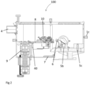
Fig. 2 zeigt einen Längsschnitt durch die Messzelle 100. -
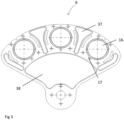
Fig. 3 zeigt einen Probenteller 8 der Messzelle 100. -
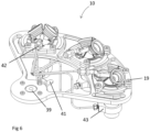
Fig. 4 ,5 und6 zeigen verschiedene Ansichten und Merkmale der Spektroskopiekammern 10 der Messzelle 100. -
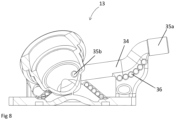
Fig. 7 und8 zeigen den Deckel 13 der Spektroskopiekammer 10. - Das Gehäuse der Messzelle (
Fig. 1 und2 ) besteht bevorzugt aus eloxiertem Aluminium und kann direkt in den Strahlengang des IR-Spektrometers platziert werden. Es stellt einen in sich abgeschlossenen Probenraum dar. Durch Spülgasanschlüsse für Inertgas (1a-c) ist sichergestellt, dass die Atmosphäre innerhalb des Raumes während der gesamten Messzeit konstant gehalten werden kann und somit Schwankungen in Temperatur und Wasserdampf-, sowie Kohlenstoffdioxidkonzentrationen außerhalb des Gehäuses keinen Einfluss auf resultierende IR-Spektren nehmen. An der linken und rechten Flanke enthält das Gehäuse eine Durchführung mit Teleskoparm (2), sodass es an ein handelsübliches FTIR Spektrometer angeschlossen werden kann. Der Deckel enthält außerdem Fenster bevorzugt aus Acrylglas (3), welche zur Beobachtung des Probenraumes dienen, sowie einen Anschluss für beheizte Gasleitungen (4). - Im Gehäuse platziert ist, neben Bohrungen für ein handelsübliches, optisches Spiegelsystem zur Aufnahme von DRIFTS Spektren (5a-c), eine Arretierung (6) inkl. Servomotor (7), die zum Ausrichten und Fixieren des Probentellers (8) in horizontaler Position dient. Der Probenteller (
Fig. 3 ) besteht bevorzugt aus Aluminium, ist auf einem Dreh-/Hub-Aktor (9) ebenfalls in dem Gehäuse verbaut und fungiert als Halter für drei untereinander identische Spektroskopiekammern (10). - Eine solche Spektroskopiekammer (
Fig. 4 und5 ) besteht aus drei Bauteilen: einem Unterbau (11), einem Probentiegel (12) und einem kuppelförmigen Deckel (13). Alle Teile sind während der Messung über eine Klemmplatte (14) und zwei Klemmen (15) sowohl miteinander, als auch mit dem Probenteller fest verbunden. Dazu wird der Unterbau in eine Vertiefung (16) in den Probenteller gelegt und anschließend die Klemmplatte mittels eines Passstifts (17) auf dem Probenteller positioniert. Der Probentiegel wird durch die Klemmplatte in den Unterbau eingeführt und mittels Deckel, der im zusammengebauten Zustand auf die Ränder des Tiegels drückt, an den Unterbau angepresst. Jedes der drei Bauteile verfügt über einen ringförmigen Hohlraum (18a-c), in dem sich jeweils ein O-Ring befindet. Diese lassen im zusammengebauten Zustand das Innere der Zelle gegenüber der Umgebung (18b, c) gasdicht werden oder dichten die einzelnen Bauteile gegeneinander ab (18a), in dem die Klemmen in den Probenteller geschraubt werden (19). - Der zylindrische Probentiegel besteht bevorzugt aus einer wärmeleitfähigen Keramik, durch dessen Vertikale eine Bohrung geht (20), die dazu dient das Reaktionsgas durch das Probenmaterial aus der Spektroskopiekammer zu leiten. Die Bohrung weitet sich nach oben hin auf ca. 6 mm auf, sodass sie dort als Probenbehälter (21) dient. Durch die Verwendung eines Gitters oder einer inerten Watte (22) wird gewährleistet, dass das zu untersuchende Material im Probenbehälter zurückgehalten wird und dass das Gas dennoch durch die Probe hindurch strömen kann. Die Verwendung von Einsetzen wie beispielsweise maßangefertigte Glasfritten und anderen Durchmessern ist ebenfalls denkbar.
- Der Unterbau ist aus Edelstahl gefertigt und enthält am oberen Ende eine Aussparung, in die der Probentiegel eingeführt werden kann. Seitlich unterhalb der Endposition des Probentiegels ist ein handelsüblicher metallgedichteter Gasanschluss (23) angeschweißt. Dieser dient dazu die Gase mit Reaktionsprodukten aus der Spektroskopiekammer zu leiten, nachdem sie die Probe durchströmt haben. Er ist über eine Bohrung (24), die sich in drei Wege aufteilt und in eine Richtung bis an das obere Ende des Unterbaus reicht, über den Probentiegel mit dem Inneren der Spektroskopiekammer verbunden. Das andere Ende der Bohrung führt zu einem ebenfalls angeschweißten metallgedichteten Anschluss, durch den ein Thermoelement (25) bis in die Probenschüttung eingeführt, abgedichtet und fixiert werden kann. Dieses regelt eine in den Unterbau platzierte Heizpatrone (26), sodass eine Temperaturmessung, sowie -regelung auf Reaktionstemperatur direkt in dem Probenmaterial ermöglicht wird. Zur weiteren Überwachung dient ein in dem Unterbau platziertes Thermoelement (27).
- Der Deckel (13,
Fig. 7 und8 ) besteht ebenfalls bevorzugt aus Edelstahl und weist zwei Kegel auf (28), in die jeweils zwei Bohrungen mit Innengewinden (29) eingearbeitet sind. In diese Bohrungen werden runde infrarotdurchlässige Fenster (30) eingeschraubt, die jeweils über einen Fensterhalter (31), PTFE-Dichtscheibe und O-Ring (32) zum Inneren der Spektroskopiekammer abgedichtet werden. Pro Seite können bis zu zwei Messfenster eingebaut werden, zwischen denen ein kleiner Luftspalt bei höheren Temperaturen als Isolator dient. Geeignete Fenstermaterialien sind beispielsweise KBr, ZnSe und CaF2. Der Deckel wird mittels Nut (33) so auf dem Probenteller positioniert, dass die IR-Strahlung durch die Messfenster der einen Seite auf die Probe einstrahlt und auf der anderen Seite die diffus-reflektierte Strahlung die Kammer verlassen kann. In den Deckel ist ein Kanal (34) eingearbeitet, an dessen Ende ein handelsüblicher metallgedichteter Gasanschluss (35a) angeschweißt ist. Dieser dient dem Einlass der Reaktionsgase in die Spektroskopiekammer. Er ist so positioniert, dass das Gas unterhalb der Messfenster einströmt (35b) und über kurze Verweilwege durch das Probenmaterial geleitet wird. Große Totvolumina werden auf diesem Wege vermieden. Zur Vermeidung von Kondensation bzw. Ablagerung von kondensierbaren Reaktionsgasen und/oder -produkten sowohl im Deckel als auch an den Messfenstern, kann der Deckel mittels Heizdrähten aktiv beheizt werden. Diese sind in der Abbildung nicht dargestellt, können aber mittels sich an der Außenseite des Deckels befindenden Ösen (36) gleichmäßig um den Deckel und den Kegel gewickelt werden. Eine Temperaturregelung erfolgt dabei über ein zwischen die Kegel platziertes Thermoelement. Der Deckel selbst wird zu Isolationszwecken bevorzugt in eine Hochtemperatursilikonhaube gegossen. Bei der Verwendung von Reaktionsgasen, die an Edelstahl reagieren können, kann der Deckel zuvor mit einem chemisch inerten Material beschichtet werden. - Um ein Überhitzen des Motors zu vermeiden, sind am Probenteller zur verbesserten Wärmeabfuhr Rillen eingearbeitet. Weitere Abnahmen auf dem Teller, insbesondere zwischen den Spektroskopiekammern (37) und nahe der Motoraufnahme (38) unterstützen die Wärmeabfuhr und reduzieren das zu bewegende Gewicht. Bei Reaktionstemperaturen über 300 °C ist es notwendig, die Dichtflächen aktiv zu kühlen. Dies kann durch einen zweigeteilten Probenteller erfolgen, in den schmale Kanäle unterhalb der Dichtflächen von Deckel und oberhalb der Fläche des Unterbaus eingearbeitet sind, durch die ein Kühlmedium beispielsweise Wasser oder bei höheren Temperaturen Silikonöl gespült wird. Über Schlauchanschlüsse, die durch das Gehäuse geführt werden, kann das Kühlmedium durch den Probenteller geführt werden. Darüber hinaus kann zusätzlich bei sehr hohen Reaktionstemperaturen das Material der Klemmplatte aus einem schlecht wärmeleitfähigen Material wie beispielsweise Keramik oder Quarzglas gewählt werden.
- Damit die Spektroskopiekammern (
Fig. 6 ) abwechselnd in den Strahlengang gebracht werden können, ohne den Probenraum öffnen zu müssen, sind diese drei auf einem Probenteller befestigt. Dieser wird mittels einer Aufnahme (39) mit dem Dreh- und Hubmotor (9) verbunden. Der Drehmotor wird dazu genutzt die Kammern im Halbkreis horizontal zu bewegen, sodass diejenige Spektroskopiekammer unter der Spiegeloptik ausgerichtet werden kann, dessen Probe vermessen werden soll. Eine Hubbewegung ist zusätzlich vor und nach der Drehbewegung notwendig, um ein Anschlagen der Kammer gegen die in Messposition sehr eng umfassende Spiegeloptik zu vermeiden. Eine Drehbewegung kann also nur erfolgen, sobald sich die Spektroskopiekammern deutlich unterhalb der Spiegeloptik befinden. Bei den Motoren handelt es sich um präzise Steppermotoren mit sehr hohen Auflösungen, sodass eine Positionierung im µm Bereich ermöglicht wird und reproduzierbar durchgeführt werden kann. Im Gehäuse sind zwei Endschalter (40) platziert, die zur exakten Positionierung als Referenzwert genutzt werden. Dabei kann es sich um mechanische Schalter wie hier dargestellt (41), oder auch optische Schalter wie beispielsweise Lichtschranken handeln. - Zur Gasversorgung der Spektroskopiekammern dient eine nicht dargestellte Versorgungsstation, aus der neben bei Raumtemperatur gasförmigen Edukte auch flüssige oder feste Edukte zunächst in die Gasphase überführt und anschließend der Messzelle zugeführt werden können. Darüber hinaus können über beheizte Transferleitungen auch gasförmige Proben aus einer Reaktionsanlage in die Spektroskopiekammern überführt werden. Der Transfer der Reaktionsgase von der Gasversorgung bzw. von der Reaktionsanlage in die Spektroskopiekammern erfolgte dabei mittels eines speziell angefertigten Heizschlauches. Dieser beinhaltet sechs Einzelleitungen, die von der beheizten Gasversorgungsstation gebündelt zum Gehäuse der Messzelle geleitet und an dieser befestigt werden (4). Innerhalb der Probenraumes bzw. des Gehäuses teilt sich der Heizschlauch auf sechs separate und jeweils aus Solltemperatur beheizte Leitungen auf. Dabei führt pro Spektroskopiekammer jeweils eine Leitung zum Reaktionsgaseinlass am Deckel (42) und eine zum Reaktions-(Produkt)gasauslass am Unterbau der Kammer (43).
- Neben der Aufnahme von DRIFTS-Spektren unter Verwendung einer Katalysatorprobe, ist auch die Aufnahme des reinen Gasphasenspektrums der in die Reaktionszelle einströmenden Reaktionsgase von Interesse. Dieses kann vom in situ Probenspektrum des Katalysators abgezogen werden, um ein Resultatspektrum zu erhalten, das lediglich Oberflächenspezies zeigt. Dies ist insbesondere dann von Bedeutung, wenn Banden der Gasphasenmoleküle sich mit denen der Adsorbate überlappen.
- Durch den Einsatz der erfindungsgemäßen Messzelle, die insbesondere für die DRIFT-Spektroskopie geeignet ist, können nun anhand von 4 Probenmessungen, von denen jeweils zwei der Aufnahme von Hintergrundspektren und 2 der Aufnahme von Reaktandenspektren dienen, in der Messzelle durchgeführt werden, sodass eine Auswertung anhand der Kubelka-Munk-Funktion ermöglicht wird. Die Aufnahme der Spektren erfolgt dabei unter den exakt gleichen, wie die mit denen im Reaktor herrschenden Bedingungen. Dadurch können sowohl Gasphasenspektren, als auch Oberflächenspezies auf der Katalysatoroberfläche und damit das Reaktionsgeschehen im Reaktor ohne hohe Hintergrundbeiträge sicher bestimmt werden.
- Die prinzipielle Vorgehensweise wird nachfolgend erläutert. Die Messfenster für den Ein- und Austritt der verwendeten bzw. der entstandenen Strahlung bestehen aus einem infrarot durchlässigen Material z.B. aus Calciumfluorid (CaF2).
- Die Messzelle besteht aus drei Spektroskopiekammern, von denen eine mit einem inerten Material (Weißstandard, z.B. CaF2-Pulver), und zwei mit der im Weißstandard verdünnten Katalysatorprobe befüllt sind. Die mit der Referenzsubstanz gefüllte Spektroskopiekammer dient der Aufnahme des Gasphasenspektrums. Dazu wird vor jeder Gasphasenmessung in dieser Kammer ein temperatur- und druckabhängiges Spektrum mit einem IR-inaktivem Gas (z.B. H2) aufgenommen. Anschließend wird eine aus dem Reaktor entnommene Gasprobe über eine Verbindungsleitung in diese Spektroskopiekammer überführt und ein weiteres Spektrum aufgenommen. Anschließende Subtraktion des Referenzspektrums CaF2/H2 vom letztgenannten Spektrum führt zum Spektrum der entnommenen Gasprobe.
- Eine zweite Spektroskopiekammer dient der Aufnahme der Referenzspektren des im Weißstandard verdünnten Katalysators bei vorgegebener Temperatur und Druck und wird dauerhaft mit IR-inaktivem Gas gespült. Eine Aufnahme erfolgt dabei unmittelbar vor Messung in Spektroskopiekammer 3. In die dritte Spektroskopiekammer, welche ebenfalls mit verdünntem Katalysator gefüllt ist, wird eine aus dem Reaktor entnommene Gasprobe geleitet und ein Spektrum aufgenommen. Dabei entspricht die entnommene Gasprobe der Probe, die in die erste Spektroskopiekammer über den reinen Weißstandard geleitet wird.
- Durch Subtraktion des Referenzspektrums des Katalysators aus Spektroskopiekammer zwei vom Spektrum aus Kammer drei wird ein Spektrum erhalten, das sowohl Gasphasenmoleküle, als auch Katalysatoroberflächenspezies enthält. Wird von diesem Spektrum das im ersten Schritt erhaltene Spektrum der Gasprobe (Spektroskopiekammer 1) subtrahiert, gelangt man schließlich zu dem Spektrum der Spezies auf der Katalysatoroberfläche, das für das Verständnis der heterogen katalysierten Reaktion wesentlich ist.
- Da die 3 Spektroskopiekammern abwechselnd in den IR-Strahl bei völlig identischen Messbedingungen (IR-Quelle, Detektor Probenraum/Gehäuse) bewegt werden können, ist das letztlich erhaltene Spektrum weitgehend frei von der Auswertung störender Hintergrundbeiträge. Darüber hinaus ist sowohl die Darstellung der reinen Gasphase, als auch der Oberflächenspezies voneinander unabhängig möglich.
- Zusammenfassend können die wesentlichen Merkmale und Vorteile der erfindungsgemäßen Messzelle wie folgt dargestellt werden:
Referenz und Katalysator werden unter identischen, den Bedingungen im eigentlichen Reaktor entsprechend, gemessen; 3 Spektroskopiekammern gewährleisten Identität von Strahlungsquelle, Detektor und Probenraum bei jeder Messung, - Deckel der Messzelle/Dome mit Gaseinlass direkt unterhalb der Messfenster führt zu kleinem Totvolumen, keine Bypassströmungen; 2 Messfenster pro Seite, Fenster beheizt durch Heizdraht bedeutet keine Kondensation von Edukten oder Produkten an den Messfenstern und dem Dome,
geringer Kontakt zwischen Reaktanten und Metallteilen, Temperaturkontrolle in der Katalysatorschüttung (Probenschüttung), Ausstattung und Anpassung für Isopotenzialspektroskopie. -
- 100
- Messzelle (DRIFTS-Messzelle)
- 1a-c
- Spülgasanschlüsse für Inertgas
- 2
- Teleskoparm
- 3
- Fenster
- 4
- beheizte Gasleitungen
- 5a-c
- optisches Spiegelsystem zur Aufnahme von DRIFT-Spektren
- 6
- Arretierung
- 7
- Servomotor
- 8
- Probenteller
- 9
- Dreh-/Hub-Aktor
- 10
- Spektroskopiekammer
- 11
- Unterbau
- 12
- Probentiegel
- 13
- Deckel
- 14
- Klemmplatte
- 15
- Klemmen
- 16
- Vertiefung
- 17
- Passstift
- 18a-c
- Hohlraum
- 19
- Verschraubung
- 20
- Bohrung
- 21
- Probenbehälter
- 22
- Inerte Watte/Gitter
- 23
- Gasanschluss
- 24
- Bohrung
- 25
- Thermoelement
- 26
- Heizpatrone
- 27
- Thermoelement
- 28
- Kegel
- 20
- Bohrung mit Innengewinde
- 30
- IR durchlässiges Fenster
- 31
- Fensterhalter
- 32
- PTFE Dichtscheibe und O-Ring
- 33
- Nut
- 34
- Kanal
- 35a
- Gasanschluss
- 35b
- Einströmstelle
- 36
- Ösen
- 37
- Spektroskopiekammer
- 38
- Motoraufnahme
- 39
- Aufnahme
- 40
- Endschalter
- 41
- mechanischer Schalter
- 42
- Reaktionsgaseinlass am Deckel
- 43
- Reaktionsgasauslass
Claims (12)
- Messzelle (100) zur Untersuchung von Proben mittels elektromagnetischer Strahlung, bevorzugt mit der DRIFT-Spektroskopie, welche Strahlenein- und -austrittsfenster (30), ein optisches Spiegelsystem (5a-c) und einen Probenteller (8) aufweist, dadurch gekennzeichnet, dass die Messzelle (100) umfasst Spülgasanschlüsse (1a-c), ein Spiegelsystem zur Aufnahme von DRIFT-Spektren (5a-c), einen Probenteller (8) mit mindestens 3 Spektroskopiekammern (10), die auf dem Probenteller befestigt sind, der über eine Aufnahme (39) mit einem Dreh- und Hubmotor (9) verbunden ist, wodurch die Kammern (10) horizontal bewegt und in den Strahlengang gedreht und unter der Spiegeloptik (5a-c) ausgerichtet werden können, und wobei jede der Kammern (10) einen Unterbau (11), einen Probentiegel (12) und einen Deckel (13) aufweist, wobei diese 3 Bauteile durch Mittel (14, 15, 19) gasdicht miteinander verbunden und gegenüber der Umgebung abgeschlossen sind, der Probentiegel (12) mit einer Bohrung (20) versehen ist, durch die Reaktionsgas aus einem externen, mit der Messzelle verbundenen Reaktor durch das Probenmaterial und aus der Kammer (10) geleitet wird, und jede Kammer (10) einen Deckel (13) mit zwei Kegeln (28) aufweist, in die für elektromagnetische Strahlung, insbesondere für IR-Strahlung, durchlässige Fenster (30) eingesetzt und so angeordnet sind, dass eingestrahlte und die Messzelle verlassende Strahlung durch diese Fenster (30) hindurchtreten können, wobei der Deckel (13) einen Kanal (34) mit einem Gasanschluss (35a) zur Einleitung von Reaktionsgasen aus einem externen Reaktor (42) in die Kammer (10) aufweist, und wobei die Kammer (10) einen Reaktionsgasauslass (43) im Unterbau (11) der Kammer (10) aufweist.
- Messzelle (100) nach Anspruch 1, dadurch gekennzeichnet, dass diese zur Probenaufnahme über gasdichte Leitungen mit einem externen Reaktor verbunden ist.
- Messzelle (100) nach Anspruch 1 oder 2, dadurch gekennzeichnet, dass der Gasanschluss (35a) und die Einströmstelle (35b) so angeordnet sind, dass das aus dem externen Reaktor zugeführte Gas direkt unterhalb der Messfenster (30) in die Spektroskopiekammer (10) einströmt.
- Messzelle (100) nach einem der Ansprüche 1 bis 3, dadurch gekennzeichnet, dass der Deckel (13) der Kammern (10) Heizdrähte zur aktiven Beheizung des Deckels und/oder der Fenster (30) aufweist.
- Messzelle (100) nach einem der Ansprüche 1 bis 4, dadurch gekennzeichnet, dass jede Spektroskopiekammer (10) ein Thermoelement (25) aufweist, das bis in die Probenschüttung eingeführt, abgedichtet und fixiert werden kann.
- Messzelle (100) nach einem der Ansprüche 1 bis 5, dadurch gekennzeichnet, dass sich in dem Unterbau (11) der Kammer (10) eine Heizpatrone befindet, die über das Thermoelement (25) geregelt wird.
- Messzelle (100) nach einem der Ansprüche 1 bis 6, dadurch gekennzeichnet, dass diese im Unterbau (11) der Spektroskopiekammer (10) ein Thermoelement (27) aufweist.
- Verwendung einer Messzelle (100) zur DRIFT-Spektroskopie von heterogen katalysierten Reaktionen.
- Verwendung nach Anspruch 8, dadurch gekennzeichnet, das die Messzelle (100) als Vorrichtung in der Isopotenzial-Spektroskopie verwendet wird.
- Verwendung nach Anspruch 8 oder 9, dadurch gekennzeichnet, dass die Messzelle (100) mit einem externen Reaktor über gasdichte Leitungen verbunden ist.
- Verfahren zur Untersuchung heterogen katalysierter Reaktionen mittels der DRIFT-Spektroskopie, dadurch gekennzeichnet, dass eine Messzelle (100) nach einem der Ansprüche 1 bis 7 verwendet wird.
- Verfahren nach Anspruch 11, dadurch gekennzeichnet, dass die Untersuchung mittels Isopotenzial-Spektroskopie erfolgt.
Priority Applications (2)
| Application Number | Priority Date | Filing Date | Title |
|---|---|---|---|
| EP22174700.9A EP4279902B1 (de) | 2022-05-20 | 2022-05-20 | Messzelle zur untersuchung von proben mittels elektromagnetischer strahlung |
| US18/199,253 US20230375479A1 (en) | 2022-05-20 | 2023-05-18 | Measuring cell for the examination of samples by means of electromagnetic radiation |
Applications Claiming Priority (1)
| Application Number | Priority Date | Filing Date | Title |
|---|---|---|---|
| EP22174700.9A EP4279902B1 (de) | 2022-05-20 | 2022-05-20 | Messzelle zur untersuchung von proben mittels elektromagnetischer strahlung |
Publications (3)
| Publication Number | Publication Date |
|---|---|
| EP4279902A1 true EP4279902A1 (de) | 2023-11-22 |
| EP4279902B1 EP4279902B1 (de) | 2025-11-05 |
| EP4279902C0 EP4279902C0 (de) | 2025-11-05 |
Family
ID=81750724
Family Applications (1)
| Application Number | Title | Priority Date | Filing Date |
|---|---|---|---|
| EP22174700.9A Active EP4279902B1 (de) | 2022-05-20 | 2022-05-20 | Messzelle zur untersuchung von proben mittels elektromagnetischer strahlung |
Country Status (2)
| Country | Link |
|---|---|
| US (1) | US20230375479A1 (de) |
| EP (1) | EP4279902B1 (de) |
Cited By (2)
| Publication number | Priority date | Publication date | Assignee | Title |
|---|---|---|---|---|
| CN119290537A (zh) * | 2024-12-13 | 2025-01-10 | 苏州华承食品有限公司 | 一种药残留检测装置及药残留检测方法 |
| EP4617640A1 (de) * | 2024-03-12 | 2025-09-17 | Reacnostics GmbH | Optische anordnung zum exakten und reproduzierbaren austausch zweier messkammern zur drift-spektroskopie |
Citations (2)
| Publication number | Priority date | Publication date | Assignee | Title |
|---|---|---|---|---|
| DE19910291A1 (de) | 1999-03-09 | 2000-09-14 | Basf Ag | Meßzelle, Spektrometer sowie Spektroskopieverfahren zur Untersuchung von Proben mittels elektromagnetischer Strahlung |
| WO2021078817A1 (en) | 2019-10-21 | 2021-04-29 | REACNOSTICS GmbH | Device and method for determination of a catalyst state in a chemical reactor |
-
2022
- 2022-05-20 EP EP22174700.9A patent/EP4279902B1/de active Active
-
2023
- 2023-05-18 US US18/199,253 patent/US20230375479A1/en active Pending
Patent Citations (2)
| Publication number | Priority date | Publication date | Assignee | Title |
|---|---|---|---|---|
| DE19910291A1 (de) | 1999-03-09 | 2000-09-14 | Basf Ag | Meßzelle, Spektrometer sowie Spektroskopieverfahren zur Untersuchung von Proben mittels elektromagnetischer Strahlung |
| WO2021078817A1 (en) | 2019-10-21 | 2021-04-29 | REACNOSTICS GmbH | Device and method for determination of a catalyst state in a chemical reactor |
Non-Patent Citations (6)
| Title |
|---|
| APPL. SPECTROSC. REV., vol. 37, 2002, pages 347 - 364 |
| BRAVO-SUAREZ J J ET AL: "Design characteristics of in situ and operando ultraviolet-visible and vibrational spectroscopic reaction cells for heterogeneous catalysis", CATALYSIS REVIEWS - SCIENCE AND ENGINEERING USA, vol. 59, no. 4, 2 October 2017 (2017-10-02), pages 295 - 445, XP009539694, ISSN: 0161-4940, DOI: 10.1080/01614940.2017.1360071 * |
| DANIEL C ET AL: "Spatially resolved catalysis in microstructured reactors by IR spectroscopy: CO oxidation over mono- and bifunctional Pt catalysts", JOURNAL OF CATALYSIS, ACADEMIC PRESS, DULUTH, MN, US, vol. 272, no. 1, 25 May 2010 (2010-05-25), pages 55 - 64, XP027051446, ISSN: 0021-9517, [retrieved on 20100514] * |
| DROCHNER A ET AL: "A New DRIFTS Cell for the In-Situ Investigation of Heterogeneously Catalyzed Reactions", CHEMICAL ENGINEERING & TECHNOLOGY, J. WILEY, HOBOKEN, USA, vol. 23, no. 4, 4 April 2000 (2000-04-04), pages 319 - 322, XP071788486, ISSN: 0930-7516, DOI: 10.1002/(SICI)1521-4125(200004)23:4<319::AID-CEAT319>3.0.CO;2-4 * |
| E.H. KORTE: "Analytiker-Taschenbuch", 1990, SPRINGER-VERLAG, pages: 91 - 123 |
| ZELLEN: "Probenbehälter und deren Auswertung erheblich ein", 1993, ACS PUBLICATIONS, pages: 351 - 375 |
Cited By (2)
| Publication number | Priority date | Publication date | Assignee | Title |
|---|---|---|---|---|
| EP4617640A1 (de) * | 2024-03-12 | 2025-09-17 | Reacnostics GmbH | Optische anordnung zum exakten und reproduzierbaren austausch zweier messkammern zur drift-spektroskopie |
| CN119290537A (zh) * | 2024-12-13 | 2025-01-10 | 苏州华承食品有限公司 | 一种药残留检测装置及药残留检测方法 |
Also Published As
| Publication number | Publication date |
|---|---|
| US20230375479A1 (en) | 2023-11-23 |
| EP4279902B1 (de) | 2025-11-05 |
| EP4279902C0 (de) | 2025-11-05 |
Similar Documents
| Publication | Publication Date | Title |
|---|---|---|
| EP1012598B1 (de) | Verfahren und vorrichtung zum untersuchen von chemischen reaktionen in parallel geschalteten, miniaturisierten reaktoren | |
| EP4279902B1 (de) | Messzelle zur untersuchung von proben mittels elektromagnetischer strahlung | |
| DE2363775C3 (de) | Gerät zur Untersuchung mikroskopischer Objekte durch Pyrolyse | |
| DE102010022017A1 (de) | Verfahren zur Probenvorbereitung bei chromatographischen Trennmethoden und Vorrichtungen zur Durchführung einer Probenvorbereitung | |
| DE102010038329B4 (de) | IR-Spektrometer mit berührungsloser Temperaturmessung | |
| DE102012105101B3 (de) | Thermoanalysevorrichtung | |
| EP2003441A1 (de) | ATR-Sensor | |
| EP0578798B1 (de) | Gerät zur analyse einer medizinischen probe | |
| Blanco et al. | Determination of polymorphic purity by near infrared spectrometry | |
| EP0591758B1 (de) | Mehrkomponenten-Analysengerät | |
| DE102010022016A1 (de) | Vorrichtung zur Durchführung einer Probenvorbereitung | |
| DE19918956A1 (de) | Verfahren zur automatisierten Untersuchung katalytischer und spektroskopischer Eigenschaften der Komponenten kombinatorischer Bibliotheken | |
| EP3866963B1 (de) | Vorrichtung und verfahren zur untersuchung von reaktionen | |
| DE10132252B4 (de) | Vorrichtung zur Durchführung von katalytischen Tests | |
| DE102015214414A1 (de) | Verfahren und System zur Ermittlung biologischer Eigenschaften von Proben | |
| DE102011016059B4 (de) | Verfahren zur Korrektur von Raman-spektroskopischen Daten in einem Mehrphasensystem | |
| DE102014014414B4 (de) | Verfahren und Anordnung zur Wasserstoff- Sensorik | |
| AT513661B1 (de) | Rheometerkammer | |
| DE19910291A1 (de) | Meßzelle, Spektrometer sowie Spektroskopieverfahren zur Untersuchung von Proben mittels elektromagnetischer Strahlung | |
| DE10125126A1 (de) | Integriertes miniaturisiertes chemisches Labor mit bildverarbeitender Erfassung einer Detektorfläche | |
| EP1398078A2 (de) | Verfahren und Vorrichtung zur parallelisierten Prüfung von Feststoffen | |
| DE202005001438U1 (de) | Vorrichtung zur Erfassung von Kenngrößen organischer Substanzen | |
| DE10336086A1 (de) | Vorrichtung zur Durchführung von katalytischen Tests | |
| DE19908387A1 (de) | Verfahren zum Trocknen und/oder zum Aufschluß einer zu analysierenden Probe sowie Ofen zur Durchführung des Verfahrens | |
| DE102025119686A1 (de) | Durchflusssonde, Vorrichtung und Verfahren für die instrumentelle Prozessbadanalytik |
Legal Events
| Date | Code | Title | Description |
|---|---|---|---|
| PUAI | Public reference made under article 153(3) epc to a published international application that has entered the european phase |
Free format text: ORIGINAL CODE: 0009012 |
|
| STAA | Information on the status of an ep patent application or granted ep patent |
Free format text: STATUS: THE APPLICATION HAS BEEN PUBLISHED |
|
| AK | Designated contracting states |
Kind code of ref document: A1 Designated state(s): AL AT BE BG CH CY CZ DE DK EE ES FI FR GB GR HR HU IE IS IT LI LT LU LV MC MK MT NL NO PL PT RO RS SE SI SK SM TR |
|
| STAA | Information on the status of an ep patent application or granted ep patent |
Free format text: STATUS: REQUEST FOR EXAMINATION WAS MADE |
|
| 17P | Request for examination filed |
Effective date: 20240522 |
|
| RBV | Designated contracting states (corrected) |
Designated state(s): AL AT BE BG CH CY CZ DE DK EE ES FI FR GB GR HR HU IE IS IT LI LT LU LV MC MK MT NL NO PL PT RO RS SE SI SK SM TR |
|
| GRAP | Despatch of communication of intention to grant a patent |
Free format text: ORIGINAL CODE: EPIDOSNIGR1 |
|
| STAA | Information on the status of an ep patent application or granted ep patent |
Free format text: STATUS: GRANT OF PATENT IS INTENDED |
|
| RIC1 | Information provided on ipc code assigned before grant |
Ipc: G01N 21/35 20140101ALN20250520BHEP Ipc: G01N 21/15 20060101ALN20250520BHEP Ipc: G01N 21/03 20060101ALN20250520BHEP Ipc: G01N 21/75 20060101ALI20250520BHEP Ipc: G01N 21/3504 20140101ALI20250520BHEP Ipc: G01N 21/09 20060101AFI20250520BHEP |
|
| INTG | Intention to grant announced |
Effective date: 20250603 |
|
| GRAS | Grant fee paid |
Free format text: ORIGINAL CODE: EPIDOSNIGR3 |
|
| GRAA | (expected) grant |
Free format text: ORIGINAL CODE: 0009210 |
|
| STAA | Information on the status of an ep patent application or granted ep patent |
Free format text: STATUS: THE PATENT HAS BEEN GRANTED |
|
| AK | Designated contracting states |
Kind code of ref document: B1 Designated state(s): AL AT BE BG CH CY CZ DE DK EE ES FI FR GB GR HR HU IE IS IT LI LT LU LV MC MK MT NL NO PL PT RO RS SE SI SK SM TR |
|
| REG | Reference to a national code |
Ref country code: CH Ref legal event code: F10 Free format text: ST27 STATUS EVENT CODE: U-0-0-F10-F00 (AS PROVIDED BY THE NATIONAL OFFICE) Effective date: 20251105 Ref country code: GB Ref legal event code: FG4D Free format text: NOT ENGLISH |
|
| REG | Reference to a national code |
Ref country code: DE Ref legal event code: R096 Ref document number: 502022006001 Country of ref document: DE |
|
| REG | Reference to a national code |
Ref country code: IE Ref legal event code: FG4D Free format text: LANGUAGE OF EP DOCUMENT: GERMAN |
|
| U01 | Request for unitary effect filed |
Effective date: 20251124 |
|
| U07 | Unitary effect registered |
Designated state(s): AT BE BG DE DK EE FI FR IT LT LU LV MT NL PT RO SE SI Effective date: 20251128 |
|
| PGFP | Annual fee paid to national office [announced via postgrant information from national office to epo] |
Ref country code: GB Payment date: 20260324 Year of fee payment: 5 |
|
| PG25 | Lapsed in a contracting state [announced via postgrant information from national office to epo] |
Ref country code: ES Free format text: LAPSE BECAUSE OF FAILURE TO SUBMIT A TRANSLATION OF THE DESCRIPTION OR TO PAY THE FEE WITHIN THE PRESCRIBED TIME-LIMIT Effective date: 20251105 |
|
| PG25 | Lapsed in a contracting state [announced via postgrant information from national office to epo] |
Ref country code: NO Free format text: LAPSE BECAUSE OF FAILURE TO SUBMIT A TRANSLATION OF THE DESCRIPTION OR TO PAY THE FEE WITHIN THE PRESCRIBED TIME-LIMIT Effective date: 20260205 |
|
| PG25 | Lapsed in a contracting state [announced via postgrant information from national office to epo] |
Ref country code: HR Free format text: LAPSE BECAUSE OF FAILURE TO SUBMIT A TRANSLATION OF THE DESCRIPTION OR TO PAY THE FEE WITHIN THE PRESCRIBED TIME-LIMIT Effective date: 20251105 |
|
| PG25 | Lapsed in a contracting state [announced via postgrant information from national office to epo] |
Ref country code: RS Free format text: LAPSE BECAUSE OF FAILURE TO SUBMIT A TRANSLATION OF THE DESCRIPTION OR TO PAY THE FEE WITHIN THE PRESCRIBED TIME-LIMIT Effective date: 20260205 |
|
| PG25 | Lapsed in a contracting state [announced via postgrant information from national office to epo] |
Ref country code: IS Free format text: LAPSE BECAUSE OF FAILURE TO SUBMIT A TRANSLATION OF THE DESCRIPTION OR TO PAY THE FEE WITHIN THE PRESCRIBED TIME-LIMIT Effective date: 20260305 |
|
| U20 | Renewal fee for the european patent with unitary effect paid |
Year of fee payment: 5 Effective date: 20260316 |
|
| PG25 | Lapsed in a contracting state [announced via postgrant information from national office to epo] |
Ref country code: PL Free format text: LAPSE BECAUSE OF FAILURE TO SUBMIT A TRANSLATION OF THE DESCRIPTION OR TO PAY THE FEE WITHIN THE PRESCRIBED TIME-LIMIT Effective date: 20251105 |