EP4279848B1 - Procédé et appareil de refroidissement d'un débit riche en co2 - Google Patents
Procédé et appareil de refroidissement d'un débit riche en co2 Download PDFInfo
- Publication number
- EP4279848B1 EP4279848B1 EP23163363.7A EP23163363A EP4279848B1 EP 4279848 B1 EP4279848 B1 EP 4279848B1 EP 23163363 A EP23163363 A EP 23163363A EP 4279848 B1 EP4279848 B1 EP 4279848B1
- Authority
- EP
- European Patent Office
- Prior art keywords
- flow
- heat exchanger
- intermediate fluid
- pressure
- fluid
- Prior art date
- Legal status (The legal status is an assumption and is not a legal conclusion. Google has not performed a legal analysis and makes no representation as to the accuracy of the status listed.)
- Active
Links
Images



Classifications
-
- F—MECHANICAL ENGINEERING; LIGHTING; HEATING; WEAPONS; BLASTING
- F25—REFRIGERATION OR COOLING; COMBINED HEATING AND REFRIGERATION SYSTEMS; HEAT PUMP SYSTEMS; MANUFACTURE OR STORAGE OF ICE; LIQUEFACTION SOLIDIFICATION OF GASES
- F25J—LIQUEFACTION, SOLIDIFICATION OR SEPARATION OF GASES OR GASEOUS OR LIQUEFIED GASEOUS MIXTURES BY PRESSURE AND COLD TREATMENT OR BY BRINGING THEM INTO THE SUPERCRITICAL STATE
- F25J3/00—Processes or apparatus for separating the constituents of gaseous or liquefied gaseous mixtures involving the use of liquefaction or solidification
- F25J3/06—Processes or apparatus for separating the constituents of gaseous or liquefied gaseous mixtures involving the use of liquefaction or solidification by partial condensation
- F25J3/063—Processes or apparatus for separating the constituents of gaseous or liquefied gaseous mixtures involving the use of liquefaction or solidification by partial condensation characterised by the separated product stream
- F25J3/067—Processes or apparatus for separating the constituents of gaseous or liquefied gaseous mixtures involving the use of liquefaction or solidification by partial condensation characterised by the separated product stream separation of carbon dioxide
-
- F—MECHANICAL ENGINEERING; LIGHTING; HEATING; WEAPONS; BLASTING
- F25—REFRIGERATION OR COOLING; COMBINED HEATING AND REFRIGERATION SYSTEMS; HEAT PUMP SYSTEMS; MANUFACTURE OR STORAGE OF ICE; LIQUEFACTION SOLIDIFICATION OF GASES
- F25J—LIQUEFACTION, SOLIDIFICATION OR SEPARATION OF GASES OR GASEOUS OR LIQUEFIED GASEOUS MIXTURES BY PRESSURE AND COLD TREATMENT OR BY BRINGING THEM INTO THE SUPERCRITICAL STATE
- F25J3/00—Processes or apparatus for separating the constituents of gaseous or liquefied gaseous mixtures involving the use of liquefaction or solidification
- F25J3/02—Processes or apparatus for separating the constituents of gaseous or liquefied gaseous mixtures involving the use of liquefaction or solidification by rectification, i.e. by continuous interchange of heat and material between a vapour stream and a liquid stream
- F25J3/0228—Processes or apparatus for separating the constituents of gaseous or liquefied gaseous mixtures involving the use of liquefaction or solidification by rectification, i.e. by continuous interchange of heat and material between a vapour stream and a liquid stream characterised by the separated product stream
- F25J3/0266—Processes or apparatus for separating the constituents of gaseous or liquefied gaseous mixtures involving the use of liquefaction or solidification by rectification, i.e. by continuous interchange of heat and material between a vapour stream and a liquid stream characterised by the separated product stream separation of carbon dioxide
-
- F—MECHANICAL ENGINEERING; LIGHTING; HEATING; WEAPONS; BLASTING
- F25—REFRIGERATION OR COOLING; COMBINED HEATING AND REFRIGERATION SYSTEMS; HEAT PUMP SYSTEMS; MANUFACTURE OR STORAGE OF ICE; LIQUEFACTION SOLIDIFICATION OF GASES
- F25J—LIQUEFACTION, SOLIDIFICATION OR SEPARATION OF GASES OR GASEOUS OR LIQUEFIED GASEOUS MIXTURES BY PRESSURE AND COLD TREATMENT OR BY BRINGING THEM INTO THE SUPERCRITICAL STATE
- F25J1/00—Processes or apparatus for liquefying or solidifying gases or gaseous mixtures
- F25J1/02—Processes or apparatus for liquefying or solidifying gases or gaseous mixtures requiring the use of refrigeration, e.g. of helium or hydrogen ; Details and kind of the refrigeration system used; Integration with other units or processes; Controlling aspects of the process
- F25J1/0228—Coupling of the liquefaction unit to other units or processes, so-called integrated processes
- F25J1/0235—Heat exchange integration
-
- F—MECHANICAL ENGINEERING; LIGHTING; HEATING; WEAPONS; BLASTING
- F25—REFRIGERATION OR COOLING; COMBINED HEATING AND REFRIGERATION SYSTEMS; HEAT PUMP SYSTEMS; MANUFACTURE OR STORAGE OF ICE; LIQUEFACTION SOLIDIFICATION OF GASES
- F25J—LIQUEFACTION, SOLIDIFICATION OR SEPARATION OF GASES OR GASEOUS OR LIQUEFIED GASEOUS MIXTURES BY PRESSURE AND COLD TREATMENT OR BY BRINGING THEM INTO THE SUPERCRITICAL STATE
- F25J1/00—Processes or apparatus for liquefying or solidifying gases or gaseous mixtures
- F25J1/0002—Processes or apparatus for liquefying or solidifying gases or gaseous mixtures characterised by the fluid to be liquefied
- F25J1/0027—Oxides of carbon, e.g. CO2
-
- F—MECHANICAL ENGINEERING; LIGHTING; HEATING; WEAPONS; BLASTING
- F25—REFRIGERATION OR COOLING; COMBINED HEATING AND REFRIGERATION SYSTEMS; HEAT PUMP SYSTEMS; MANUFACTURE OR STORAGE OF ICE; LIQUEFACTION SOLIDIFICATION OF GASES
- F25J—LIQUEFACTION, SOLIDIFICATION OR SEPARATION OF GASES OR GASEOUS OR LIQUEFIED GASEOUS MIXTURES BY PRESSURE AND COLD TREATMENT OR BY BRINGING THEM INTO THE SUPERCRITICAL STATE
- F25J1/00—Processes or apparatus for liquefying or solidifying gases or gaseous mixtures
- F25J1/003—Processes or apparatus for liquefying or solidifying gases or gaseous mixtures characterised by the kind of cold generation within the liquefaction unit for compensating heat leaks and liquid production
- F25J1/0047—Processes or apparatus for liquefying or solidifying gases or gaseous mixtures characterised by the kind of cold generation within the liquefaction unit for compensating heat leaks and liquid production using an "external" refrigerant stream in a closed vapor compression cycle
- F25J1/0052—Processes or apparatus for liquefying or solidifying gases or gaseous mixtures characterised by the kind of cold generation within the liquefaction unit for compensating heat leaks and liquid production using an "external" refrigerant stream in a closed vapor compression cycle by vaporising a liquid refrigerant stream
-
- F—MECHANICAL ENGINEERING; LIGHTING; HEATING; WEAPONS; BLASTING
- F25—REFRIGERATION OR COOLING; COMBINED HEATING AND REFRIGERATION SYSTEMS; HEAT PUMP SYSTEMS; MANUFACTURE OR STORAGE OF ICE; LIQUEFACTION SOLIDIFICATION OF GASES
- F25J—LIQUEFACTION, SOLIDIFICATION OR SEPARATION OF GASES OR GASEOUS OR LIQUEFIED GASEOUS MIXTURES BY PRESSURE AND COLD TREATMENT OR BY BRINGING THEM INTO THE SUPERCRITICAL STATE
- F25J1/00—Processes or apparatus for liquefying or solidifying gases or gaseous mixtures
- F25J1/006—Processes or apparatus for liquefying or solidifying gases or gaseous mixtures characterised by the refrigerant fluid used
- F25J1/008—Hydrocarbons
- F25J1/0085—Ethane; Ethylene
-
- F—MECHANICAL ENGINEERING; LIGHTING; HEATING; WEAPONS; BLASTING
- F25—REFRIGERATION OR COOLING; COMBINED HEATING AND REFRIGERATION SYSTEMS; HEAT PUMP SYSTEMS; MANUFACTURE OR STORAGE OF ICE; LIQUEFACTION SOLIDIFICATION OF GASES
- F25J—LIQUEFACTION, SOLIDIFICATION OR SEPARATION OF GASES OR GASEOUS OR LIQUEFIED GASEOUS MIXTURES BY PRESSURE AND COLD TREATMENT OR BY BRINGING THEM INTO THE SUPERCRITICAL STATE
- F25J1/00—Processes or apparatus for liquefying or solidifying gases or gaseous mixtures
- F25J1/006—Processes or apparatus for liquefying or solidifying gases or gaseous mixtures characterised by the refrigerant fluid used
- F25J1/008—Hydrocarbons
- F25J1/009—Hydrocarbons with four or more carbon atoms
-
- F—MECHANICAL ENGINEERING; LIGHTING; HEATING; WEAPONS; BLASTING
- F25—REFRIGERATION OR COOLING; COMBINED HEATING AND REFRIGERATION SYSTEMS; HEAT PUMP SYSTEMS; MANUFACTURE OR STORAGE OF ICE; LIQUEFACTION SOLIDIFICATION OF GASES
- F25J—LIQUEFACTION, SOLIDIFICATION OR SEPARATION OF GASES OR GASEOUS OR LIQUEFIED GASEOUS MIXTURES BY PRESSURE AND COLD TREATMENT OR BY BRINGING THEM INTO THE SUPERCRITICAL STATE
- F25J1/00—Processes or apparatus for liquefying or solidifying gases or gaseous mixtures
- F25J1/02—Processes or apparatus for liquefying or solidifying gases or gaseous mixtures requiring the use of refrigeration, e.g. of helium or hydrogen ; Details and kind of the refrigeration system used; Integration with other units or processes; Controlling aspects of the process
- F25J1/0203—Processes or apparatus for liquefying or solidifying gases or gaseous mixtures requiring the use of refrigeration, e.g. of helium or hydrogen ; Details and kind of the refrigeration system used; Integration with other units or processes; Controlling aspects of the process using a single-component refrigerant [SCR] fluid in a closed vapor compression cycle
- F25J1/0204—Processes or apparatus for liquefying or solidifying gases or gaseous mixtures requiring the use of refrigeration, e.g. of helium or hydrogen ; Details and kind of the refrigeration system used; Integration with other units or processes; Controlling aspects of the process using a single-component refrigerant [SCR] fluid in a closed vapor compression cycle as a single flow SCR cycle
-
- F—MECHANICAL ENGINEERING; LIGHTING; HEATING; WEAPONS; BLASTING
- F25—REFRIGERATION OR COOLING; COMBINED HEATING AND REFRIGERATION SYSTEMS; HEAT PUMP SYSTEMS; MANUFACTURE OR STORAGE OF ICE; LIQUEFACTION SOLIDIFICATION OF GASES
- F25J—LIQUEFACTION, SOLIDIFICATION OR SEPARATION OF GASES OR GASEOUS OR LIQUEFIED GASEOUS MIXTURES BY PRESSURE AND COLD TREATMENT OR BY BRINGING THEM INTO THE SUPERCRITICAL STATE
- F25J1/00—Processes or apparatus for liquefying or solidifying gases or gaseous mixtures
- F25J1/02—Processes or apparatus for liquefying or solidifying gases or gaseous mixtures requiring the use of refrigeration, e.g. of helium or hydrogen ; Details and kind of the refrigeration system used; Integration with other units or processes; Controlling aspects of the process
- F25J1/0211—Processes or apparatus for liquefying or solidifying gases or gaseous mixtures requiring the use of refrigeration, e.g. of helium or hydrogen ; Details and kind of the refrigeration system used; Integration with other units or processes; Controlling aspects of the process using a multi-component refrigerant [MCR] fluid in a closed vapor compression cycle
- F25J1/0212—Processes or apparatus for liquefying or solidifying gases or gaseous mixtures requiring the use of refrigeration, e.g. of helium or hydrogen ; Details and kind of the refrigeration system used; Integration with other units or processes; Controlling aspects of the process using a multi-component refrigerant [MCR] fluid in a closed vapor compression cycle as a single flow MCR cycle
-
- F—MECHANICAL ENGINEERING; LIGHTING; HEATING; WEAPONS; BLASTING
- F25—REFRIGERATION OR COOLING; COMBINED HEATING AND REFRIGERATION SYSTEMS; HEAT PUMP SYSTEMS; MANUFACTURE OR STORAGE OF ICE; LIQUEFACTION SOLIDIFICATION OF GASES
- F25J—LIQUEFACTION, SOLIDIFICATION OR SEPARATION OF GASES OR GASEOUS OR LIQUEFIED GASEOUS MIXTURES BY PRESSURE AND COLD TREATMENT OR BY BRINGING THEM INTO THE SUPERCRITICAL STATE
- F25J1/00—Processes or apparatus for liquefying or solidifying gases or gaseous mixtures
- F25J1/02—Processes or apparatus for liquefying or solidifying gases or gaseous mixtures requiring the use of refrigeration, e.g. of helium or hydrogen ; Details and kind of the refrigeration system used; Integration with other units or processes; Controlling aspects of the process
- F25J1/0221—Processes or apparatus for liquefying or solidifying gases or gaseous mixtures requiring the use of refrigeration, e.g. of helium or hydrogen ; Details and kind of the refrigeration system used; Integration with other units or processes; Controlling aspects of the process using the cold stored in an external cryogenic component in an open refrigeration loop
- F25J1/0222—Processes or apparatus for liquefying or solidifying gases or gaseous mixtures requiring the use of refrigeration, e.g. of helium or hydrogen ; Details and kind of the refrigeration system used; Integration with other units or processes; Controlling aspects of the process using the cold stored in an external cryogenic component in an open refrigeration loop in combination with an intermediate heat exchange fluid between the cryogenic component and the fluid to be liquefied
-
- F—MECHANICAL ENGINEERING; LIGHTING; HEATING; WEAPONS; BLASTING
- F25—REFRIGERATION OR COOLING; COMBINED HEATING AND REFRIGERATION SYSTEMS; HEAT PUMP SYSTEMS; MANUFACTURE OR STORAGE OF ICE; LIQUEFACTION SOLIDIFICATION OF GASES
- F25J—LIQUEFACTION, SOLIDIFICATION OR SEPARATION OF GASES OR GASEOUS OR LIQUEFIED GASEOUS MIXTURES BY PRESSURE AND COLD TREATMENT OR BY BRINGING THEM INTO THE SUPERCRITICAL STATE
- F25J1/00—Processes or apparatus for liquefying or solidifying gases or gaseous mixtures
- F25J1/02—Processes or apparatus for liquefying or solidifying gases or gaseous mixtures requiring the use of refrigeration, e.g. of helium or hydrogen ; Details and kind of the refrigeration system used; Integration with other units or processes; Controlling aspects of the process
- F25J1/0228—Coupling of the liquefaction unit to other units or processes, so-called integrated processes
- F25J1/0235—Heat exchange integration
- F25J1/0242—Waste heat recovery, e.g. from heat of compression
-
- F—MECHANICAL ENGINEERING; LIGHTING; HEATING; WEAPONS; BLASTING
- F25—REFRIGERATION OR COOLING; COMBINED HEATING AND REFRIGERATION SYSTEMS; HEAT PUMP SYSTEMS; MANUFACTURE OR STORAGE OF ICE; LIQUEFACTION SOLIDIFICATION OF GASES
- F25J—LIQUEFACTION, SOLIDIFICATION OR SEPARATION OF GASES OR GASEOUS OR LIQUEFIED GASEOUS MIXTURES BY PRESSURE AND COLD TREATMENT OR BY BRINGING THEM INTO THE SUPERCRITICAL STATE
- F25J1/00—Processes or apparatus for liquefying or solidifying gases or gaseous mixtures
- F25J1/02—Processes or apparatus for liquefying or solidifying gases or gaseous mixtures requiring the use of refrigeration, e.g. of helium or hydrogen ; Details and kind of the refrigeration system used; Integration with other units or processes; Controlling aspects of the process
- F25J1/0243—Start-up or control of the process; Details of the apparatus used; Details of the refrigerant compression system used
- F25J1/0257—Construction and layout of liquefaction equipments, e.g. valves, machines
-
- F—MECHANICAL ENGINEERING; LIGHTING; HEATING; WEAPONS; BLASTING
- F25—REFRIGERATION OR COOLING; COMBINED HEATING AND REFRIGERATION SYSTEMS; HEAT PUMP SYSTEMS; MANUFACTURE OR STORAGE OF ICE; LIQUEFACTION SOLIDIFICATION OF GASES
- F25J—LIQUEFACTION, SOLIDIFICATION OR SEPARATION OF GASES OR GASEOUS OR LIQUEFIED GASEOUS MIXTURES BY PRESSURE AND COLD TREATMENT OR BY BRINGING THEM INTO THE SUPERCRITICAL STATE
- F25J1/00—Processes or apparatus for liquefying or solidifying gases or gaseous mixtures
- F25J1/02—Processes or apparatus for liquefying or solidifying gases or gaseous mixtures requiring the use of refrigeration, e.g. of helium or hydrogen ; Details and kind of the refrigeration system used; Integration with other units or processes; Controlling aspects of the process
- F25J1/0243—Start-up or control of the process; Details of the apparatus used; Details of the refrigerant compression system used
- F25J1/0257—Construction and layout of liquefaction equipments, e.g. valves, machines
- F25J1/0262—Details of the cold heat exchange system
- F25J1/0264—Arrangement of heat exchanger cores in parallel with different functions, e.g. different cooling streams
- F25J1/0265—Arrangement of heat exchanger cores in parallel with different functions, e.g. different cooling streams comprising cores associated exclusively with the cooling of a refrigerant stream, e.g. for auto-refrigeration or economizer
- F25J1/0268—Arrangement of heat exchanger cores in parallel with different functions, e.g. different cooling streams comprising cores associated exclusively with the cooling of a refrigerant stream, e.g. for auto-refrigeration or economizer using a dedicated refrigeration means
-
- F—MECHANICAL ENGINEERING; LIGHTING; HEATING; WEAPONS; BLASTING
- F25—REFRIGERATION OR COOLING; COMBINED HEATING AND REFRIGERATION SYSTEMS; HEAT PUMP SYSTEMS; MANUFACTURE OR STORAGE OF ICE; LIQUEFACTION SOLIDIFICATION OF GASES
- F25J—LIQUEFACTION, SOLIDIFICATION OR SEPARATION OF GASES OR GASEOUS OR LIQUEFIED GASEOUS MIXTURES BY PRESSURE AND COLD TREATMENT OR BY BRINGING THEM INTO THE SUPERCRITICAL STATE
- F25J1/00—Processes or apparatus for liquefying or solidifying gases or gaseous mixtures
- F25J1/02—Processes or apparatus for liquefying or solidifying gases or gaseous mixtures requiring the use of refrigeration, e.g. of helium or hydrogen ; Details and kind of the refrigeration system used; Integration with other units or processes; Controlling aspects of the process
- F25J1/0243—Start-up or control of the process; Details of the apparatus used; Details of the refrigerant compression system used
- F25J1/0279—Compression of refrigerant or internal recycle fluid, e.g. kind of compressor, accumulator, suction drum etc.
- F25J1/0285—Combination of different types of drivers mechanically coupled to the same refrigerant compressor, possibly split on multiple compressor casings
- F25J1/0288—Combination of different types of drivers mechanically coupled to the same refrigerant compressor, possibly split on multiple compressor casings using work extraction by mechanical coupling of compression and expansion of the refrigerant, so-called companders
-
- F—MECHANICAL ENGINEERING; LIGHTING; HEATING; WEAPONS; BLASTING
- F25—REFRIGERATION OR COOLING; COMBINED HEATING AND REFRIGERATION SYSTEMS; HEAT PUMP SYSTEMS; MANUFACTURE OR STORAGE OF ICE; LIQUEFACTION SOLIDIFICATION OF GASES
- F25J—LIQUEFACTION, SOLIDIFICATION OR SEPARATION OF GASES OR GASEOUS OR LIQUEFIED GASEOUS MIXTURES BY PRESSURE AND COLD TREATMENT OR BY BRINGING THEM INTO THE SUPERCRITICAL STATE
- F25J3/00—Processes or apparatus for separating the constituents of gaseous or liquefied gaseous mixtures involving the use of liquefaction or solidification
- F25J3/02—Processes or apparatus for separating the constituents of gaseous or liquefied gaseous mixtures involving the use of liquefaction or solidification by rectification, i.e. by continuous interchange of heat and material between a vapour stream and a liquid stream
- F25J3/0204—Processes or apparatus for separating the constituents of gaseous or liquefied gaseous mixtures involving the use of liquefaction or solidification by rectification, i.e. by continuous interchange of heat and material between a vapour stream and a liquid stream characterised by the feed stream
- F25J3/0223—H2/CO mixtures, i.e. synthesis gas; Water gas or shifted synthesis gas
-
- F—MECHANICAL ENGINEERING; LIGHTING; HEATING; WEAPONS; BLASTING
- F25—REFRIGERATION OR COOLING; COMBINED HEATING AND REFRIGERATION SYSTEMS; HEAT PUMP SYSTEMS; MANUFACTURE OR STORAGE OF ICE; LIQUEFACTION SOLIDIFICATION OF GASES
- F25J—LIQUEFACTION, SOLIDIFICATION OR SEPARATION OF GASES OR GASEOUS OR LIQUEFIED GASEOUS MIXTURES BY PRESSURE AND COLD TREATMENT OR BY BRINGING THEM INTO THE SUPERCRITICAL STATE
- F25J3/00—Processes or apparatus for separating the constituents of gaseous or liquefied gaseous mixtures involving the use of liquefaction or solidification
- F25J3/02—Processes or apparatus for separating the constituents of gaseous or liquefied gaseous mixtures involving the use of liquefaction or solidification by rectification, i.e. by continuous interchange of heat and material between a vapour stream and a liquid stream
- F25J3/0228—Processes or apparatus for separating the constituents of gaseous or liquefied gaseous mixtures involving the use of liquefaction or solidification by rectification, i.e. by continuous interchange of heat and material between a vapour stream and a liquid stream characterised by the separated product stream
- F25J3/0252—Processes or apparatus for separating the constituents of gaseous or liquefied gaseous mixtures involving the use of liquefaction or solidification by rectification, i.e. by continuous interchange of heat and material between a vapour stream and a liquid stream characterised by the separated product stream separation of hydrogen
-
- F—MECHANICAL ENGINEERING; LIGHTING; HEATING; WEAPONS; BLASTING
- F25—REFRIGERATION OR COOLING; COMBINED HEATING AND REFRIGERATION SYSTEMS; HEAT PUMP SYSTEMS; MANUFACTURE OR STORAGE OF ICE; LIQUEFACTION SOLIDIFICATION OF GASES
- F25J—LIQUEFACTION, SOLIDIFICATION OR SEPARATION OF GASES OR GASEOUS OR LIQUEFIED GASEOUS MIXTURES BY PRESSURE AND COLD TREATMENT OR BY BRINGING THEM INTO THE SUPERCRITICAL STATE
- F25J3/00—Processes or apparatus for separating the constituents of gaseous or liquefied gaseous mixtures involving the use of liquefaction or solidification
- F25J3/02—Processes or apparatus for separating the constituents of gaseous or liquefied gaseous mixtures involving the use of liquefaction or solidification by rectification, i.e. by continuous interchange of heat and material between a vapour stream and a liquid stream
- F25J3/0228—Processes or apparatus for separating the constituents of gaseous or liquefied gaseous mixtures involving the use of liquefaction or solidification by rectification, i.e. by continuous interchange of heat and material between a vapour stream and a liquid stream characterised by the separated product stream
- F25J3/0257—Processes or apparatus for separating the constituents of gaseous or liquefied gaseous mixtures involving the use of liquefaction or solidification by rectification, i.e. by continuous interchange of heat and material between a vapour stream and a liquid stream characterised by the separated product stream separation of nitrogen
-
- F—MECHANICAL ENGINEERING; LIGHTING; HEATING; WEAPONS; BLASTING
- F25—REFRIGERATION OR COOLING; COMBINED HEATING AND REFRIGERATION SYSTEMS; HEAT PUMP SYSTEMS; MANUFACTURE OR STORAGE OF ICE; LIQUEFACTION SOLIDIFICATION OF GASES
- F25J—LIQUEFACTION, SOLIDIFICATION OR SEPARATION OF GASES OR GASEOUS OR LIQUEFIED GASEOUS MIXTURES BY PRESSURE AND COLD TREATMENT OR BY BRINGING THEM INTO THE SUPERCRITICAL STATE
- F25J3/00—Processes or apparatus for separating the constituents of gaseous or liquefied gaseous mixtures involving the use of liquefaction or solidification
- F25J3/06—Processes or apparatus for separating the constituents of gaseous or liquefied gaseous mixtures involving the use of liquefaction or solidification by partial condensation
- F25J3/0605—Processes or apparatus for separating the constituents of gaseous or liquefied gaseous mixtures involving the use of liquefaction or solidification by partial condensation characterised by the feed stream
- F25J3/061—Natural gas or substitute natural gas
-
- F—MECHANICAL ENGINEERING; LIGHTING; HEATING; WEAPONS; BLASTING
- F25—REFRIGERATION OR COOLING; COMBINED HEATING AND REFRIGERATION SYSTEMS; HEAT PUMP SYSTEMS; MANUFACTURE OR STORAGE OF ICE; LIQUEFACTION SOLIDIFICATION OF GASES
- F25J—LIQUEFACTION, SOLIDIFICATION OR SEPARATION OF GASES OR GASEOUS OR LIQUEFIED GASEOUS MIXTURES BY PRESSURE AND COLD TREATMENT OR BY BRINGING THEM INTO THE SUPERCRITICAL STATE
- F25J3/00—Processes or apparatus for separating the constituents of gaseous or liquefied gaseous mixtures involving the use of liquefaction or solidification
- F25J3/06—Processes or apparatus for separating the constituents of gaseous or liquefied gaseous mixtures involving the use of liquefaction or solidification by partial condensation
- F25J3/063—Processes or apparatus for separating the constituents of gaseous or liquefied gaseous mixtures involving the use of liquefaction or solidification by partial condensation characterised by the separated product stream
- F25J3/0635—Processes or apparatus for separating the constituents of gaseous or liquefied gaseous mixtures involving the use of liquefaction or solidification by partial condensation characterised by the separated product stream separation of CnHm with 1 carbon atom or more
-
- F—MECHANICAL ENGINEERING; LIGHTING; HEATING; WEAPONS; BLASTING
- F25—REFRIGERATION OR COOLING; COMBINED HEATING AND REFRIGERATION SYSTEMS; HEAT PUMP SYSTEMS; MANUFACTURE OR STORAGE OF ICE; LIQUEFACTION SOLIDIFICATION OF GASES
- F25J—LIQUEFACTION, SOLIDIFICATION OR SEPARATION OF GASES OR GASEOUS OR LIQUEFIED GASEOUS MIXTURES BY PRESSURE AND COLD TREATMENT OR BY BRINGING THEM INTO THE SUPERCRITICAL STATE
- F25J3/00—Processes or apparatus for separating the constituents of gaseous or liquefied gaseous mixtures involving the use of liquefaction or solidification
- F25J3/08—Separating gaseous impurities from gases or gaseous mixtures or from liquefied gases or liquefied gaseous mixtures
-
- F—MECHANICAL ENGINEERING; LIGHTING; HEATING; WEAPONS; BLASTING
- F25—REFRIGERATION OR COOLING; COMBINED HEATING AND REFRIGERATION SYSTEMS; HEAT PUMP SYSTEMS; MANUFACTURE OR STORAGE OF ICE; LIQUEFACTION SOLIDIFICATION OF GASES
- F25J—LIQUEFACTION, SOLIDIFICATION OR SEPARATION OF GASES OR GASEOUS OR LIQUEFIED GASEOUS MIXTURES BY PRESSURE AND COLD TREATMENT OR BY BRINGING THEM INTO THE SUPERCRITICAL STATE
- F25J2200/00—Processes or apparatus using separation by rectification
- F25J2200/02—Processes or apparatus using separation by rectification in a single pressure main column system
-
- F—MECHANICAL ENGINEERING; LIGHTING; HEATING; WEAPONS; BLASTING
- F25—REFRIGERATION OR COOLING; COMBINED HEATING AND REFRIGERATION SYSTEMS; HEAT PUMP SYSTEMS; MANUFACTURE OR STORAGE OF ICE; LIQUEFACTION SOLIDIFICATION OF GASES
- F25J—LIQUEFACTION, SOLIDIFICATION OR SEPARATION OF GASES OR GASEOUS OR LIQUEFIED GASEOUS MIXTURES BY PRESSURE AND COLD TREATMENT OR BY BRINGING THEM INTO THE SUPERCRITICAL STATE
- F25J2200/00—Processes or apparatus using separation by rectification
- F25J2200/70—Refluxing the column with a condensed part of the feed stream, i.e. fractionator top is stripped or self-rectified
-
- F—MECHANICAL ENGINEERING; LIGHTING; HEATING; WEAPONS; BLASTING
- F25—REFRIGERATION OR COOLING; COMBINED HEATING AND REFRIGERATION SYSTEMS; HEAT PUMP SYSTEMS; MANUFACTURE OR STORAGE OF ICE; LIQUEFACTION SOLIDIFICATION OF GASES
- F25J—LIQUEFACTION, SOLIDIFICATION OR SEPARATION OF GASES OR GASEOUS OR LIQUEFIED GASEOUS MIXTURES BY PRESSURE AND COLD TREATMENT OR BY BRINGING THEM INTO THE SUPERCRITICAL STATE
- F25J2210/00—Processes characterised by the type or other details of the feed stream
- F25J2210/06—Splitting of the feed stream, e.g. for treating or cooling in different ways
-
- F—MECHANICAL ENGINEERING; LIGHTING; HEATING; WEAPONS; BLASTING
- F25—REFRIGERATION OR COOLING; COMBINED HEATING AND REFRIGERATION SYSTEMS; HEAT PUMP SYSTEMS; MANUFACTURE OR STORAGE OF ICE; LIQUEFACTION SOLIDIFICATION OF GASES
- F25J—LIQUEFACTION, SOLIDIFICATION OR SEPARATION OF GASES OR GASEOUS OR LIQUEFIED GASEOUS MIXTURES BY PRESSURE AND COLD TREATMENT OR BY BRINGING THEM INTO THE SUPERCRITICAL STATE
- F25J2210/00—Processes characterised by the type or other details of the feed stream
- F25J2210/62—Liquefied natural gas [LNG]; Natural gas liquids [NGL]; Liquefied petroleum gas [LPG]
-
- F—MECHANICAL ENGINEERING; LIGHTING; HEATING; WEAPONS; BLASTING
- F25—REFRIGERATION OR COOLING; COMBINED HEATING AND REFRIGERATION SYSTEMS; HEAT PUMP SYSTEMS; MANUFACTURE OR STORAGE OF ICE; LIQUEFACTION SOLIDIFICATION OF GASES
- F25J—LIQUEFACTION, SOLIDIFICATION OR SEPARATION OF GASES OR GASEOUS OR LIQUEFIED GASEOUS MIXTURES BY PRESSURE AND COLD TREATMENT OR BY BRINGING THEM INTO THE SUPERCRITICAL STATE
- F25J2215/00—Processes characterised by the type or other details of the product stream
- F25J2215/04—Recovery of liquid products
-
- F—MECHANICAL ENGINEERING; LIGHTING; HEATING; WEAPONS; BLASTING
- F25—REFRIGERATION OR COOLING; COMBINED HEATING AND REFRIGERATION SYSTEMS; HEAT PUMP SYSTEMS; MANUFACTURE OR STORAGE OF ICE; LIQUEFACTION SOLIDIFICATION OF GASES
- F25J—LIQUEFACTION, SOLIDIFICATION OR SEPARATION OF GASES OR GASEOUS OR LIQUEFIED GASEOUS MIXTURES BY PRESSURE AND COLD TREATMENT OR BY BRINGING THEM INTO THE SUPERCRITICAL STATE
- F25J2220/00—Processes or apparatus involving steps for the removal of impurities
- F25J2220/02—Separating impurities in general from the feed stream
-
- F—MECHANICAL ENGINEERING; LIGHTING; HEATING; WEAPONS; BLASTING
- F25—REFRIGERATION OR COOLING; COMBINED HEATING AND REFRIGERATION SYSTEMS; HEAT PUMP SYSTEMS; MANUFACTURE OR STORAGE OF ICE; LIQUEFACTION SOLIDIFICATION OF GASES
- F25J—LIQUEFACTION, SOLIDIFICATION OR SEPARATION OF GASES OR GASEOUS OR LIQUEFIED GASEOUS MIXTURES BY PRESSURE AND COLD TREATMENT OR BY BRINGING THEM INTO THE SUPERCRITICAL STATE
- F25J2220/00—Processes or apparatus involving steps for the removal of impurities
- F25J2220/40—Separating high boiling, i.e. less volatile components from air, e.g. CO2, hydrocarbons
-
- F—MECHANICAL ENGINEERING; LIGHTING; HEATING; WEAPONS; BLASTING
- F25—REFRIGERATION OR COOLING; COMBINED HEATING AND REFRIGERATION SYSTEMS; HEAT PUMP SYSTEMS; MANUFACTURE OR STORAGE OF ICE; LIQUEFACTION SOLIDIFICATION OF GASES
- F25J—LIQUEFACTION, SOLIDIFICATION OR SEPARATION OF GASES OR GASEOUS OR LIQUEFIED GASEOUS MIXTURES BY PRESSURE AND COLD TREATMENT OR BY BRINGING THEM INTO THE SUPERCRITICAL STATE
- F25J2220/00—Processes or apparatus involving steps for the removal of impurities
- F25J2220/80—Separating impurities from carbon dioxide, e.g. H2O or water-soluble contaminants
- F25J2220/82—Separating low boiling, i.e. more volatile components, e.g. He, H2, CO, Air gases, CH4
-
- F—MECHANICAL ENGINEERING; LIGHTING; HEATING; WEAPONS; BLASTING
- F25—REFRIGERATION OR COOLING; COMBINED HEATING AND REFRIGERATION SYSTEMS; HEAT PUMP SYSTEMS; MANUFACTURE OR STORAGE OF ICE; LIQUEFACTION SOLIDIFICATION OF GASES
- F25J—LIQUEFACTION, SOLIDIFICATION OR SEPARATION OF GASES OR GASEOUS OR LIQUEFIED GASEOUS MIXTURES BY PRESSURE AND COLD TREATMENT OR BY BRINGING THEM INTO THE SUPERCRITICAL STATE
- F25J2235/00—Processes or apparatus involving steps for increasing the pressure or for conveying of liquid process streams
- F25J2235/60—Processes or apparatus involving steps for increasing the pressure or for conveying of liquid process streams the fluid being (a mixture of) hydrocarbons
-
- F—MECHANICAL ENGINEERING; LIGHTING; HEATING; WEAPONS; BLASTING
- F25—REFRIGERATION OR COOLING; COMBINED HEATING AND REFRIGERATION SYSTEMS; HEAT PUMP SYSTEMS; MANUFACTURE OR STORAGE OF ICE; LIQUEFACTION SOLIDIFICATION OF GASES
- F25J—LIQUEFACTION, SOLIDIFICATION OR SEPARATION OF GASES OR GASEOUS OR LIQUEFIED GASEOUS MIXTURES BY PRESSURE AND COLD TREATMENT OR BY BRINGING THEM INTO THE SUPERCRITICAL STATE
- F25J2270/00—Refrigeration techniques used
- F25J2270/12—External refrigeration with liquid vaporising loop
-
- F—MECHANICAL ENGINEERING; LIGHTING; HEATING; WEAPONS; BLASTING
- F25—REFRIGERATION OR COOLING; COMBINED HEATING AND REFRIGERATION SYSTEMS; HEAT PUMP SYSTEMS; MANUFACTURE OR STORAGE OF ICE; LIQUEFACTION SOLIDIFICATION OF GASES
- F25J—LIQUEFACTION, SOLIDIFICATION OR SEPARATION OF GASES OR GASEOUS OR LIQUEFIED GASEOUS MIXTURES BY PRESSURE AND COLD TREATMENT OR BY BRINGING THEM INTO THE SUPERCRITICAL STATE
- F25J2270/00—Refrigeration techniques used
- F25J2270/14—External refrigeration with work-producing gas expansion loop
-
- F—MECHANICAL ENGINEERING; LIGHTING; HEATING; WEAPONS; BLASTING
- F25—REFRIGERATION OR COOLING; COMBINED HEATING AND REFRIGERATION SYSTEMS; HEAT PUMP SYSTEMS; MANUFACTURE OR STORAGE OF ICE; LIQUEFACTION SOLIDIFICATION OF GASES
- F25J—LIQUEFACTION, SOLIDIFICATION OR SEPARATION OF GASES OR GASEOUS OR LIQUEFIED GASEOUS MIXTURES BY PRESSURE AND COLD TREATMENT OR BY BRINGING THEM INTO THE SUPERCRITICAL STATE
- F25J2270/00—Refrigeration techniques used
- F25J2270/60—Closed external refrigeration cycle with single component refrigerant [SCR], e.g. C1-, C2- or C3-hydrocarbons
-
- F—MECHANICAL ENGINEERING; LIGHTING; HEATING; WEAPONS; BLASTING
- F25—REFRIGERATION OR COOLING; COMBINED HEATING AND REFRIGERATION SYSTEMS; HEAT PUMP SYSTEMS; MANUFACTURE OR STORAGE OF ICE; LIQUEFACTION SOLIDIFICATION OF GASES
- F25J—LIQUEFACTION, SOLIDIFICATION OR SEPARATION OF GASES OR GASEOUS OR LIQUEFIED GASEOUS MIXTURES BY PRESSURE AND COLD TREATMENT OR BY BRINGING THEM INTO THE SUPERCRITICAL STATE
- F25J2270/00—Refrigeration techniques used
- F25J2270/90—External refrigeration, e.g. conventional closed-loop mechanical refrigeration unit using Freon or NH3, unspecified external refrigeration
- F25J2270/902—Details about the refrigeration cycle used, e.g. composition of refrigerant, arrangement of compressors or cascade, make up sources, use of reflux exchangers etc.
-
- F—MECHANICAL ENGINEERING; LIGHTING; HEATING; WEAPONS; BLASTING
- F25—REFRIGERATION OR COOLING; COMBINED HEATING AND REFRIGERATION SYSTEMS; HEAT PUMP SYSTEMS; MANUFACTURE OR STORAGE OF ICE; LIQUEFACTION SOLIDIFICATION OF GASES
- F25J—LIQUEFACTION, SOLIDIFICATION OR SEPARATION OF GASES OR GASEOUS OR LIQUEFIED GASEOUS MIXTURES BY PRESSURE AND COLD TREATMENT OR BY BRINGING THEM INTO THE SUPERCRITICAL STATE
- F25J2270/00—Refrigeration techniques used
- F25J2270/90—External refrigeration, e.g. conventional closed-loop mechanical refrigeration unit using Freon or NH3, unspecified external refrigeration
- F25J2270/904—External refrigeration, e.g. conventional closed-loop mechanical refrigeration unit using Freon or NH3, unspecified external refrigeration by liquid or gaseous cryogen in an open loop
-
- F—MECHANICAL ENGINEERING; LIGHTING; HEATING; WEAPONS; BLASTING
- F25—REFRIGERATION OR COOLING; COMBINED HEATING AND REFRIGERATION SYSTEMS; HEAT PUMP SYSTEMS; MANUFACTURE OR STORAGE OF ICE; LIQUEFACTION SOLIDIFICATION OF GASES
- F25J—LIQUEFACTION, SOLIDIFICATION OR SEPARATION OF GASES OR GASEOUS OR LIQUEFIED GASEOUS MIXTURES BY PRESSURE AND COLD TREATMENT OR BY BRINGING THEM INTO THE SUPERCRITICAL STATE
- F25J2290/00—Other details not covered by groups F25J2200/00 - F25J2280/00
- F25J2290/34—Details about subcooling of liquids
-
- Y—GENERAL TAGGING OF NEW TECHNOLOGICAL DEVELOPMENTS; GENERAL TAGGING OF CROSS-SECTIONAL TECHNOLOGIES SPANNING OVER SEVERAL SECTIONS OF THE IPC; TECHNICAL SUBJECTS COVERED BY FORMER USPC CROSS-REFERENCE ART COLLECTIONS [XRACs] AND DIGESTS
- Y02—TECHNOLOGIES OR APPLICATIONS FOR MITIGATION OR ADAPTATION AGAINST CLIMATE CHANGE
- Y02C—CAPTURE, STORAGE, SEQUESTRATION OR DISPOSAL OF GREENHOUSE GASES [GHG]
- Y02C20/00—Capture or disposal of greenhouse gases
- Y02C20/40—Capture or disposal of greenhouse gases of CO2
Definitions
- the present invention relates to a method and apparatus for cooling a CO2-rich flow. At least part of the frigories required for cooling, or even liquefaction, are provided by heating a methane-rich fluid, for example vaporizing a methane-rich liquid, for example containing at least 80 mol% methane or pseudo-vaporizing a methane-rich fluid in the dense phase.
- a methane-rich fluid for example vaporizing a methane-rich liquid, for example containing at least 80 mol% methane or pseudo-vaporizing a methane-rich fluid in the dense phase.
- An example of such a liquid is liquefied natural gas (LNG).
- LNG liquefied natural gas
- the transfer of frigories is achieved by using an intermediate fluid rich in ethane or ethylene to transfer the frigories from the liquefied gas, for example from the liquefied natural gas to the liquefaction of the CO2-rich flow.
- a CO2-rich stream comprises at least 70 mol% carbon dioxide, preferably at least 90 mol% carbon dioxide, or even at least 95% carbon dioxide.
- Liquefying a carbon dioxide-rich stream typically consumes electricity to provide the required refrigeration.
- Liquefied natural gas is often vaporized against seawater or another calorigen.
- the two systems have complementary requirements, as vaporizing LNG requires heat and liquefying carbon dioxide requires a source of cooling. It is therefore interesting to investigate the possibility of integrating the two systems.
- the disadvantage of option a) is the incompatibility between the enthalpy-temperature profiles of the condensing CO2 and the intermediate fluid in the heat exchanger (most of the heat is produced by the CO2 at constant temperature while the temperature of the intermediate fluid increases at a constant rate, depending on its flow rate and specific heat).
- This obstacle can be avoided, for example, by increasing the flow rate of the intermediate fluid and/or by increasing the pressure of the CO2 to approach or even exceed the critical pressure. Both solutions require increasing energy and therefore these solutions are less attractive.
- JPH04-131688 describes a closed intermediate fluid cycle that transfers cold from an LNG flow to a CO2 flow to be liquefied, the cycle including a pump to pressurize the intermediate fluid.
- the fluid used is Freon ® .
- FR2869404 describes a closed intermediate fluid cycle that transfers cold from an LNG flow to a CO2 flow to be liquefied, the intermediate fluid being ethane which vaporizes against the CO2 and liquefies against the LNG.
- the pressure of the intermediate fluid is constant.
- the present invention aims to improve known methods by reducing the risk of freezing carbon dioxide in the cooling process, or even liquefaction of carbon dioxide.
- This fluid uses an intermediate fluid to recover the cold from the LNG composed mainly of ethane and/or ethylene, which may also include methane.
- This fluid will be designated as C2 fluid.
- This fluid preferably contains at least 90 mol% of ethane or ethylene.
- This intermediate fluid preferably allows cold to be recovered down to temperatures below -60°C.
- a dedicated heat exchanger (called “LNG exchanger”) is used to exchange heat between the intermediate fluid and the methane-rich liquid, for example liquefied natural gas LNG in liquid or dense phase form.
- the LNG is heated or vaporized (depending on its pressure) against the C2 fluid which condenses and is cooled to a temperature below -50°C in a single pass or in multiple parallel passes operating at different pressures (Pc1, Pc2, PcN, where N is typically between 2 and 4), in order to limit the temperature differences between the exchanger fluids.
- the LNG exchanger will typically be a brazed aluminum or stainless steel plate and fin exchanger, a shell and tube exchanger or a printed circuit exchanger.
- the C2 fluid flows are preferably subcooled to a temperature between 2-10 K above the LNG inlet temperature in the exchanger.
- all subcooled C2 fluids are mixed at a pressure P1, possibly using at least one pump and reheated in another passage of the same exchanger to a temperature between 2 and 5 K below the bubble temperature of the mixed flows at pressure P1.
- Subcooling the C2 fluid to around -60 °C is only a means of limiting the temperature differences in the exchanger.
- the resulting flow of C2 fluid at pressure P1 is then reheated and vaporized against the condensing CO2, the CO2 ideally being at a single pressure between 10-16 bara in another multi-fluid heat exchanger, the C2 fluid passing through this exchanger either at a single pressure or in parallel at two pressures P1 and P2 ⁇ P1.
- P2 would typically correspond to the bubble pressure of the C2 fluid at about -55°C.
- the flow rate of the C2 fluid vaporized at P1 would be much smaller (e.g. 25 to 35 times smaller) than the flow rate of the C2 fluid vaporized at P2, the latter providing most of the refrigeration associated with the CO2 condensation and the former providing most of the refrigeration associated with the CO2 subcooling and reflux production for the CO2 distillation column.
- the vaporized fluid C2 to P1 (or the vaporized fluids at P1 and P2) obtained at the hot end of the heat exchanger where the CO2 condenses must be designed to produce the required flow rates at the chosen condensation pressures Pc1, Pc2, PcN for the LNG reheat exchanger.
- N streams From two available streams at two different pressures, N streams must be formed, at pressure values Pc1, Pc2, PcN and with specified flow rates. This involves compressing at least one stream and/or expanding at least one stream. It is important to enhance the pressure of the original streams (i.e., by minimizing the compression, especially if it cannot be driven by the expansion of another stream in a turbine).
- only one of the condensation pressures Pc1, Pc2, PcN is higher than P1.
- a part of the gaseous fluid C2 at P1 is compressed by a centrifugal compressor to the highest of the condensation pressures.
- the fluid C2 at the other condensation pressures is obtained by expanding the remaining fluid C2 in at least one JT valve and a centrifugal turbine.
- the number of C2 fluid flows at different pressures passing through the LNG reheat exchanger is chosen according to the composition of the C2 fluid and the type of exchanger used. In general terms, the higher the number of flows, the smaller the temperature differences between the fluids, so that the reheating can for example be achieved in a brazed aluminum plate and fin exchanger.
- JP H04 121573A describe a method and apparatus in accordance with the preambles of claims 1 and 21 respectively.
- An aim of the present invention is to limit the temperature differences at the cold end of one of the exchangers, in order to increase the efficiency of the process.
- an apparatus for recovering frigories from a methane-rich fluid, for example liquefied natural gas, for cooling and possibly liquefying, or even separating a flow rich in carbon dioxide comprising a first heat exchanger, a second heat exchanger, means for sending the carbon dioxide-rich flow to cool and possibly condense at least partially in a first heat exchanger, a closed intermediate fluid cycle comprising means for sending the intermediate fluid containing at least 80 mol% of ethane or ethylene to vaporize in the first exchanger at at least one pressure level, preferably at a single pressure level, means for sending the vaporized fluid to condense in the second heat exchanger at at least one pressure in at least one flow, preferably at a single pressure in a single flow, by heat exchange with the methane-rich fluid to form at least one flow of condensed intermediate fluid, a pump for pressurizing the at least one flow of intermediate fluid condensed, characterized in that it comprises means for sending the flow from the pump to
- FIG.1 represents a process for condensing CO2 by heat exchange with a methane-rich liquid, for example LNG, using a cycle whose fluid is 100% ethane with two fluid flows condensing in the exchanger at two different condensation pressures.
- a flow of liquefied natural gas (LNG) 1 is sent to the cold end of a heat exchanger E2 which can be a plate and fin exchanger or a printed circuit exchanger.
- the liquefied natural gas vaporizes and heats up in the exchanger E2 to produce natural gas 3 exiting the hot end preferably at a temperature above 0°C, for example room temperature.
- the fluid 1 can be a gas or a liquid.
- the heat exchanger E2 In the heat exchanger E2, two flows C2, here of ethane, 19, 21 are cooled, the flow 21 being at a lower pressure than the flow 19.
- the flow 21 passes through the heat exchanger E1 from the hot end to the cold end, condensing completely.
- the condensed flow is sent to a tank S.
- the liquid 23 of the tank S is pressurized by a pump P and mixed with the flow 19 which has condensed and which is expanded in a valve.
- the flow formed 11 is de-subcooled and therefore heated in the heat exchanger E1 to an intermediate temperature thereof, i.e. a temperature between that of the cold end and the hot end of the exchanger.
- Flow 11 is sent to the CO2 liquefier either in a thermally insulated pipe or by passing through a thermally insulated cold box common to exchanger E2 and to the CO2 liquefier.
- Flow 11 is divided into two and the two parts 13, 15 are expanded in respective valves and reheated in a heat exchanger E1 passing from the cold end to the hot end. After reheating, flow 15 is divided into two to form flows 19, 17.
- Flow 19 is compressed in a compressor C, cooled in a cooler (not shown) and sent at the outlet pressure thereof to exchanger E2.
- Flow 17 is expanded from pressure P1 in a turbine T which drives compressor C and is mixed with flow 13 to form flow 21 which enters exchanger E2.
- the flow 5 rich in carbon dioxide at between 10-16 bara is divided into two parts 51, 53.
- the flow 53 passes entirely through the exchanger E1 and is sent as reflux at the top of a distillation column K1, having condensed in the exchanger E1.
- the other part 51 cools in the exchanger E1 to the same pressure as part 53 but leaves the exchanger E1 at a temperature intermediate between those of the hot end and the cold end. Part 51 is then sent to the column K1.
- the reboiling of column K1 is provided by taking a portion 57 of the bottom liquid 55 of column K1 enriched in carbon dioxide.
- the bottom liquid 55 is sent to an intermediate level of exchanger E1 warmer than the outlet point of flow 51.
- the portion 57 is vaporized and reheated and returned to the bottom of column K1 as gas.
- the remainder 7 of the liquid 55 is subcooled in heat exchanger E1 by heat exchange with the intermediate fluid 11 and forms liquid carbon dioxide which is the product of the process.
- the overhead gas 9 of column K1 is reheated in exchanger E1 from the cold end to the hot end and leaves the system. This gas 9 is enriched in light impurities such as nitrogen, hydrogen, carbon monoxide, etc.
- the condensation pressure of the flow rate 19 of intermediate fluid in the second heat exchanger E2 is higher, preferably by at least 2 bars, than the highest of the vaporization pressures of the intermediate fluid in the first heat exchanger E1.
- FIG.2 represents a process of condensation of CO2 by heat exchange with a liquid rich in methane, for example LNG, using a cycle whose fluid C2 is 100% ethylene.
- the details of the CO2 liquefier are not given but a process identical or similar to that of the [ FIG.1 ] can be used for liquefaction.
- the fluid C2 vaporizes at two different pressures in the exchanger E2 to condense the gas rich in carbon dioxide.
- the gas 15 taken at the hot end of the exchanger E1 is divided into two.
- a part 45 is compressed in the compressor, cooled in a heat exchanger E3 and then condensed in the heat exchanger E2 against the LNG.
- the remainder 25 of the gas 15 is divided into three, a part 29 being mixed with the gas 13 to form a gas 43 which is expanded in the turbine driving the compressor and then is sent to the exchanger E2 to condense completely forming the liquid flow 47 sent to the tank S.
- Another portion 27 of the gas 25 is expanded and then sent to the heat exchanger E2 where it is condensed and subcooled, then mixed with the subcooled liquid 47.
- Another portion 41 of the gas 25 is expanded and then sent to the heat exchanger E2 where it is condensed and subcooled and then mixed with the liquid 47.
- the E2 exchanger can be a plate and fin exchanger, for example in brazed aluminum since there is a cooler downstream of the compression of the flow 45.
- the turbine is supplied by the flow of fluid C2 here ethylene at the pressure P2.
- the E3 exchanger is cooled by means of a flow 1A of vaporized LNG taken at the hot outlet of the E2 exchanger.
- the condensation pressure of the intermediate fluid flow rate 45 in the second heat exchanger is higher, preferably by at least 2 bars, than the highest of the vaporization pressures of the intermediate fluid in the first heat exchanger.
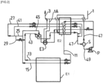
- FIG.3 represents a process of condensation of CO2 by heat exchange with LNG, using a cycle whose C2 fluid is 93.5% mol ethane and 6.5% mol methane.
- the details of the CO2 liquefier are not given but a process identical or similar to that of the [ FIG.1 ] can be used for liquefaction.
- the fluid C2 vaporizes at two different pressures in the exchanger E1 to condense the gas rich in carbon dioxide.
- the gas 15 taken at the hot end of the exchanger E1 is divided into two. A part 33 is compressed in the compressor C, cooled in a heat exchanger E3 and then condensed in the heat exchanger E2 against the LNG.
- the remainder 25 of the gas 15 is divided into two, a part 29 being mixed with the gas 13 to form a gas 43 which is expanded in the turbine T driving the compressor C and then is sent to the exchanger E2 to condense completely forming the liquid flow 35 sent to the tank S.
- the other part 27 of the gas 25 is expanded in a valve then sent to the heat exchanger E2 where it is condensed, then it is mixed with the subcooled flow 35 upstream of the tank S.
- Exchanger E3 is cooled by means of a flow 1A of vaporized LNG taken from the hot outlet of exchanger E2.
- the E2 exchanger can be a plate and fin exchanger, for example in brazed aluminum since there is a cooler E3 downstream of the compression of flow 33.
- the turbine is supplied by the fluid flow C2 at pressure P2.
- the condensation pressure of the intermediate fluid flow 33 in the second heat exchanger is higher, preferably by at least 2 bars, than the highest of the vaporization pressures of the intermediate fluid in the first heat exchanger.
- FIG.4 represents a process for condensing CO2 by heat exchange with a methane-rich liquid, for example LNG, using a cycle whose fluid is 93 mol% ethylene and 7 mol% methane with a single fluid flow condensing in the exchanger E2.
- a flow of liquefied natural gas (LNG) 1 is sent to the cold end of a heat exchanger E2 which may be a plate and fin exchanger or a printed circuit exchanger.
- the liquefied natural gas vaporizes and heats up in the exchanger E2 to produce natural gas 3 exiting the hot end preferably at a temperature above 0°C, for example room temperature.
- a flow C2, 21 is cooled.
- the flow 21 passes through the heat exchanger E1 from the hot end to the cold end, condensing completely and subcooling.
- the subcooled flow is separated in a tank S.
- the gas 25 from the tank S joins the flow 21 at the inlet of the exchanger E2.
- the liquid 23 from the tank S is pressurized by a pump P.
- the pumped flow 11 is de-cooled and therefore heated in the heat exchanger E2 to an intermediate temperature thereof.
- Flow 11 is sent to the CO2 liquefier either in an insulated pipe or by passing through an insulated cold box common to the exchanger E2 and the CO2 liquefier.
- Flow 11 becomes flow 13 and is reheated in a heat exchanger E1 by passing from the cold end to the hot end. After reheating, flow 13 is reheated again, for example to 60°C, and sent at the outlet pressure of the heater R to the exchanger E2. The flow enters the exchanger E2.
- a flow rate of 12 bypasses exchanger E1 to allow the intermediate fluid to be heated by a heater.
- the flow 5 rich in carbon dioxide at between 10-16 bara is divided into two parts 51, 53.
- the flow 53 passes entirely through the exchanger E1 and is sent as reflux at the top of a distillation column K1, having condensed in the exchanger E1.
- the other part 51 cools in the exchanger E1 to the same pressure as part 53 but leaves the exchanger E1 at a temperature intermediate between those of the hot end and the cold end. Part 51 is then sent to the column K1.
- the reboiling of column K1 is provided by taking a portion 57 of the bottom liquid 55 of column K1 enriched in carbon dioxide.
- the bottom liquid 55 is sent to an intermediate level of the exchanger E21 warmer than the outlet point of the flow 51.
- the portion 57 is vaporized and reheated and returned to the bottom of column K1 as gas.
- the remainder 7 of the liquid 55 is subcooled in the heat exchanger E1 by heat exchange with the intermediate fluid 11 and forms liquid carbon dioxide which is the product of the process.
- the overhead gas 9 of column K1 is reheated in the exchanger E1 from the cold end to the hot end and leaves the system. This gas 9 is enriched in light impurities such as nitrogen, hydrogen, carbon monoxide, etc.
- the condensation pressure of the intermediate fluid flow 19 in the second heat exchanger differs from the highest of the intermediate fluid vaporization pressures in the first heat exchanger only by the pressure losses.
- the intermediate fluid cycle does not include any compression (apart from the pump pressurization) or expansion in a turbine. Pump P is only used to compensate for pressure losses.
- THE [ FIG. 1 ], [ FIG. 2 ], [ FIG. 3 ] And [ FIG.4 ] respectively may comprise a conduit for bringing produced gas into the tank S upstream of the exchanger E2. This gas results from the heat inputs into the tank S, which vaporize a small part of the liquid it contains. The gas formed 25 is sent from the tank S and joins the gas 21.
Landscapes
- Engineering & Computer Science (AREA)
- Physics & Mathematics (AREA)
- Mechanical Engineering (AREA)
- Thermal Sciences (AREA)
- General Engineering & Computer Science (AREA)
- Chemical & Material Sciences (AREA)
- Chemical Kinetics & Catalysis (AREA)
- General Chemical & Material Sciences (AREA)
- Oil, Petroleum & Natural Gas (AREA)
- Separation By Low-Temperature Treatments (AREA)
- Carbon And Carbon Compounds (AREA)
Applications Claiming Priority (1)
| Application Number | Priority Date | Filing Date | Title |
|---|---|---|---|
| FR2204833A FR3128011B1 (fr) | 2022-05-20 | 2022-05-20 | Procédé et appareil de refroidissement d’un débit riche en CO2 |
Publications (2)
| Publication Number | Publication Date |
|---|---|
| EP4279848A1 EP4279848A1 (fr) | 2023-11-22 |
| EP4279848B1 true EP4279848B1 (fr) | 2024-11-13 |
Family
ID=82483255
Family Applications (1)
| Application Number | Title | Priority Date | Filing Date |
|---|---|---|---|
| EP23163363.7A Active EP4279848B1 (fr) | 2022-05-20 | 2023-03-22 | Procédé et appareil de refroidissement d'un débit riche en co2 |
Country Status (6)
| Country | Link |
|---|---|
| US (1) | US20230375266A1 (https=) |
| EP (1) | EP4279848B1 (https=) |
| JP (1) | JP2023171261A (https=) |
| KR (1) | KR20230162547A (https=) |
| CN (1) | CN117091352A (https=) |
| FR (1) | FR3128011B1 (https=) |
Families Citing this family (1)
| Publication number | Priority date | Publication date | Assignee | Title |
|---|---|---|---|---|
| JP2025177084A (ja) * | 2024-05-22 | 2025-12-05 | 株式会社神戸製鋼所 | 熱交換器及び熱交換システム |
Family Cites Families (16)
| Publication number | Priority date | Publication date | Assignee | Title |
|---|---|---|---|---|
| JPS5520206A (en) * | 1978-07-24 | 1980-02-13 | Showa Tansan Kk | Manufacture of saturated liquefied carbon dioxide |
| JP2566337B2 (ja) * | 1990-09-11 | 1996-12-25 | 三菱重工業株式会社 | Co▲下2▼ガスの液化方法 |
| JP3720415B2 (ja) * | 1995-05-18 | 2005-11-30 | 大阪瓦斯株式会社 | 液化炭酸製造用冷媒および液化炭酸製造設備の運転方法ならびに熱交換器 |
| JP2004069215A (ja) | 2002-08-08 | 2004-03-04 | Nippon Sanso Corp | 熱交換装置及びその制御方法並びに液化天然ガスの冷熱を利用した炭酸ガスの液化方法 |
| FR2869404A1 (fr) | 2004-04-27 | 2005-10-28 | Inst Francais Du Petrole | Procede de liquefaction du dioxyde de carbone gazeux. |
| FR2894838B1 (fr) * | 2005-12-21 | 2008-03-14 | Gaz De France Sa | Procede et systeme de capture du dioxyde de carbone present dans des fumees |
| EP2641043A2 (fr) * | 2010-11-16 | 2013-09-25 | L'Air Liquide Société Anonyme pour l'Etude et l'Exploitation des Procédés Georges Claude | Procede et appareil de purification d'un debit riche en dioxyde de carbone |
| US9410736B2 (en) * | 2011-10-22 | 2016-08-09 | Sustainable Energy Solutions, Llc | Systems and methods for integrated energy storage and cryogenic carbon capture |
| US20130283851A1 (en) * | 2012-04-26 | 2013-10-31 | Air Products And Chemicals, Inc. | Purification of Carbon Dioxide |
| CN105545390A (zh) * | 2016-01-25 | 2016-05-04 | 辽宁石油化工大学 | 一种lng冷能梯级利用方法 |
| CN109813054B (zh) * | 2017-11-22 | 2021-03-30 | 斗山重工业建设有限公司 | 利用液化天然气的冷能的二氧化碳捕集装置及发电系统 |
| FR3099234B1 (fr) * | 2019-07-26 | 2021-07-30 | Air Liquide | Procédé de récupération d’énergie frigorifique avec production d’électricité ou liquéfaction d’un courant gazeux |
| CN110864498B (zh) * | 2019-10-17 | 2021-08-27 | 深圳市燃气集团股份有限公司 | 一种lng冷能梯级利用装置和方法 |
| JP7605714B2 (ja) * | 2021-07-30 | 2024-12-24 | 株式会社吉野工業所 | 瓶口用キャップ |
| EP4191177A1 (en) * | 2021-12-01 | 2023-06-07 | Nederlandse Organisatie Voor Toegepast- Natuurwetenschappelijk Onderzoek Tno | Lng exergy optimization for sbcc |
| JP2023122693A (ja) * | 2022-02-24 | 2023-09-05 | 地方独立行政法人青森県産業技術センター | 細胞サイズリポソーム、プロシアニジン濃度推定方法、およびプロシアニジン濃度測定方法 |
-
2022
- 2022-05-20 FR FR2204833A patent/FR3128011B1/fr not_active Expired - Fee Related
-
2023
- 2023-03-22 EP EP23163363.7A patent/EP4279848B1/fr active Active
- 2023-04-06 JP JP2023061808A patent/JP2023171261A/ja active Pending
- 2023-05-17 KR KR1020230063608A patent/KR20230162547A/ko active Pending
- 2023-05-18 US US18/199,357 patent/US20230375266A1/en active Pending
- 2023-05-19 CN CN202310568477.9A patent/CN117091352A/zh active Pending
Also Published As
| Publication number | Publication date |
|---|---|
| KR20230162547A (ko) | 2023-11-28 |
| US20230375266A1 (en) | 2023-11-23 |
| FR3128011B1 (fr) | 2024-06-28 |
| FR3128011A1 (fr) | 2023-04-14 |
| EP4279848A1 (fr) | 2023-11-22 |
| JP2023171261A (ja) | 2023-12-01 |
| CN117091352A (zh) | 2023-11-21 |
Similar Documents
| Publication | Publication Date | Title |
|---|---|---|
| CN105043014B (zh) | 使用专用再喷射回路的液化天然气生产中的集成的除氮 | |
| JP6144714B2 (ja) | 中間供給ガス分離を使用した液化された天然ガスの生産における統合された窒素除去 | |
| US20140083132A1 (en) | Process for liquefaction of natural gas | |
| EP1118827B1 (fr) | Procédé de liquéfaction partielle d'un fluide contenant des hydrocarbures tel que du gaz naturel | |
| CN105004139A (zh) | 在生产液化天然气时使用制冷热泵一体地移除氮 | |
| US20150300734A1 (en) | Method for Separating a Carbon Dioxide-rich Gas by Partial Condensation and Permeation | |
| KR20210116269A (ko) | 질소 제거에 의한 lng 생산 | |
| FR2723183A1 (fr) | Procede et installation de liquefaction d'hydrogene | |
| EP4325150B1 (fr) | Procédé et appareil de refroidissement d'hydrogène | |
| EP4279848B1 (fr) | Procédé et appareil de refroidissement d'un débit riche en co2 | |
| EP2938414B1 (fr) | Procédé et appareil de séparation d'un gaz riche en dioxyde de carbone | |
| US9746233B2 (en) | Process for the separation of a gas rich in carbon dioxide | |
| EP4375602B1 (fr) | Procédé et appareil de liquéfaction et éventuellement de séparation de co2 par distillation | |
| EP4493871B1 (fr) | Procédé et appareil de refroidissement d'hydrogène | |
| EP4285061B1 (fr) | Procédé et appareil de séparation d'un débit riche en dioxyde de carbone par distillation pour produire du dioxyde de carbone liquide | |
| EP3058296B1 (fr) | Procede de deazotation du gaz naturel avec ou sans recuperation d'helium | |
| WO2025011874A2 (fr) | Procédé de liquéfaction et/ou de solidification d'un gaz riche en dioxyde de carbone | |
| EP4417915A1 (fr) | Procédé et appareil de liquéfaction d'un gaz riche en dioxyde de carbone | |
| WO2023148045A1 (fr) | Procédé et appareil de refroidissement de dioxyde de carbone et d'hydrogène | |
| FR3033397A1 (fr) | Procede de compression et de refroidissement d’un melange gazeux | |
| WO2013114020A2 (fr) | Procédé et appareil de condensation ou de pseudocondensation d'un gaz |
Legal Events
| Date | Code | Title | Description |
|---|---|---|---|
| PUAI | Public reference made under article 153(3) epc to a published international application that has entered the european phase |
Free format text: ORIGINAL CODE: 0009012 |
|
| STAA | Information on the status of an ep patent application or granted ep patent |
Free format text: STATUS: THE APPLICATION HAS BEEN PUBLISHED |
|
| AK | Designated contracting states |
Kind code of ref document: A1 Designated state(s): AL AT BE BG CH CY CZ DE DK EE ES FI FR GB GR HR HU IE IS IT LI LT LU LV MC ME MK MT NL NO PL PT RO RS SE SI SK SM TR |
|
| STAA | Information on the status of an ep patent application or granted ep patent |
Free format text: STATUS: REQUEST FOR EXAMINATION WAS MADE |
|
| 17P | Request for examination filed |
Effective date: 20240522 |
|
| RBV | Designated contracting states (corrected) |
Designated state(s): AL AT BE BG CH CY CZ DE DK EE ES FI FR GB GR HR HU IE IS IT LI LT LU LV MC ME MK MT NL NO PL PT RO RS SE SI SK SM TR |
|
| GRAP | Despatch of communication of intention to grant a patent |
Free format text: ORIGINAL CODE: EPIDOSNIGR1 |
|
| STAA | Information on the status of an ep patent application or granted ep patent |
Free format text: STATUS: GRANT OF PATENT IS INTENDED |
|
| RIC1 | Information provided on ipc code assigned before grant |
Ipc: F25J 1/02 20060101ALI20240724BHEP Ipc: F25J 1/00 20060101ALI20240724BHEP Ipc: F25J 3/02 20060101AFI20240724BHEP |
|
| INTG | Intention to grant announced |
Effective date: 20240816 |
|
| RIN1 | Information on inventor provided before grant (corrected) |
Inventor name: RAVENTOS, MARTIN Inventor name: MOREL, THOMAS Inventor name: LECLERC, MATHIEU Inventor name: DUBETTIER-GRENIER, RICHARD |
|
| GRAS | Grant fee paid |
Free format text: ORIGINAL CODE: EPIDOSNIGR3 |
|
| GRAA | (expected) grant |
Free format text: ORIGINAL CODE: 0009210 |
|
| STAA | Information on the status of an ep patent application or granted ep patent |
Free format text: STATUS: THE PATENT HAS BEEN GRANTED |
|
| AK | Designated contracting states |
Kind code of ref document: B1 Designated state(s): AL AT BE BG CH CY CZ DE DK EE ES FI FR GB GR HR HU IE IS IT LI LT LU LV MC ME MK MT NL NO PL PT RO RS SE SI SK SM TR |
|
| REG | Reference to a national code |
Ref country code: GB Ref legal event code: FG4D Free format text: NOT ENGLISH |
|
| REG | Reference to a national code |
Ref country code: CH Ref legal event code: EP |
|
| REG | Reference to a national code |
Ref country code: IE Ref legal event code: FG4D Free format text: LANGUAGE OF EP DOCUMENT: FRENCH |
|
| REG | Reference to a national code |
Ref country code: DE Ref legal event code: R096 Ref document number: 602023000985 Country of ref document: DE |
|
| REG | Reference to a national code |
Ref country code: NL Ref legal event code: FP |
|
| REG | Reference to a national code |
Ref country code: LT Ref legal event code: MG9D |
|
| PG25 | Lapsed in a contracting state [announced via postgrant information from national office to epo] |
Ref country code: HR Free format text: LAPSE BECAUSE OF FAILURE TO SUBMIT A TRANSLATION OF THE DESCRIPTION OR TO PAY THE FEE WITHIN THE PRESCRIBED TIME-LIMIT Effective date: 20241113 Ref country code: IS Free format text: LAPSE BECAUSE OF FAILURE TO SUBMIT A TRANSLATION OF THE DESCRIPTION OR TO PAY THE FEE WITHIN THE PRESCRIBED TIME-LIMIT Effective date: 20250313 Ref country code: PT Free format text: LAPSE BECAUSE OF FAILURE TO SUBMIT A TRANSLATION OF THE DESCRIPTION OR TO PAY THE FEE WITHIN THE PRESCRIBED TIME-LIMIT Effective date: 20250313 |
|
| PG25 | Lapsed in a contracting state [announced via postgrant information from national office to epo] |
Ref country code: FI Free format text: LAPSE BECAUSE OF FAILURE TO SUBMIT A TRANSLATION OF THE DESCRIPTION OR TO PAY THE FEE WITHIN THE PRESCRIBED TIME-LIMIT Effective date: 20241113 |
|
| REG | Reference to a national code |
Ref country code: AT Ref legal event code: MK05 Ref document number: 1741958 Country of ref document: AT Kind code of ref document: T Effective date: 20241113 |
|
| PG25 | Lapsed in a contracting state [announced via postgrant information from national office to epo] |
Ref country code: BG Free format text: LAPSE BECAUSE OF FAILURE TO SUBMIT A TRANSLATION OF THE DESCRIPTION OR TO PAY THE FEE WITHIN THE PRESCRIBED TIME-LIMIT Effective date: 20241113 |
|
| PG25 | Lapsed in a contracting state [announced via postgrant information from national office to epo] |
Ref country code: ES Free format text: LAPSE BECAUSE OF FAILURE TO SUBMIT A TRANSLATION OF THE DESCRIPTION OR TO PAY THE FEE WITHIN THE PRESCRIBED TIME-LIMIT Effective date: 20241113 |
|
| PG25 | Lapsed in a contracting state [announced via postgrant information from national office to epo] |
Ref country code: NO Free format text: LAPSE BECAUSE OF FAILURE TO SUBMIT A TRANSLATION OF THE DESCRIPTION OR TO PAY THE FEE WITHIN THE PRESCRIBED TIME-LIMIT Effective date: 20250213 |
|
| PG25 | Lapsed in a contracting state [announced via postgrant information from national office to epo] |
Ref country code: GR Free format text: LAPSE BECAUSE OF FAILURE TO SUBMIT A TRANSLATION OF THE DESCRIPTION OR TO PAY THE FEE WITHIN THE PRESCRIBED TIME-LIMIT Effective date: 20250214 Ref country code: LV Free format text: LAPSE BECAUSE OF FAILURE TO SUBMIT A TRANSLATION OF THE DESCRIPTION OR TO PAY THE FEE WITHIN THE PRESCRIBED TIME-LIMIT Effective date: 20241113 Ref country code: AT Free format text: LAPSE BECAUSE OF FAILURE TO SUBMIT A TRANSLATION OF THE DESCRIPTION OR TO PAY THE FEE WITHIN THE PRESCRIBED TIME-LIMIT Effective date: 20241113 |
|
| PG25 | Lapsed in a contracting state [announced via postgrant information from national office to epo] |
Ref country code: PL Free format text: LAPSE BECAUSE OF FAILURE TO SUBMIT A TRANSLATION OF THE DESCRIPTION OR TO PAY THE FEE WITHIN THE PRESCRIBED TIME-LIMIT Effective date: 20241113 |
|
| PG25 | Lapsed in a contracting state [announced via postgrant information from national office to epo] |
Ref country code: RS Free format text: LAPSE BECAUSE OF FAILURE TO SUBMIT A TRANSLATION OF THE DESCRIPTION OR TO PAY THE FEE WITHIN THE PRESCRIBED TIME-LIMIT Effective date: 20250213 |
|
| PG25 | Lapsed in a contracting state [announced via postgrant information from national office to epo] |
Ref country code: SM Free format text: LAPSE BECAUSE OF FAILURE TO SUBMIT A TRANSLATION OF THE DESCRIPTION OR TO PAY THE FEE WITHIN THE PRESCRIBED TIME-LIMIT Effective date: 20241113 |
|
| PG25 | Lapsed in a contracting state [announced via postgrant information from national office to epo] |
Ref country code: DK Free format text: LAPSE BECAUSE OF FAILURE TO SUBMIT A TRANSLATION OF THE DESCRIPTION OR TO PAY THE FEE WITHIN THE PRESCRIBED TIME-LIMIT Effective date: 20241113 |
|
| PG25 | Lapsed in a contracting state [announced via postgrant information from national office to epo] |
Ref country code: EE Free format text: LAPSE BECAUSE OF FAILURE TO SUBMIT A TRANSLATION OF THE DESCRIPTION OR TO PAY THE FEE WITHIN THE PRESCRIBED TIME-LIMIT Effective date: 20241113 |
|
| PG25 | Lapsed in a contracting state [announced via postgrant information from national office to epo] |
Ref country code: RO Free format text: LAPSE BECAUSE OF FAILURE TO SUBMIT A TRANSLATION OF THE DESCRIPTION OR TO PAY THE FEE WITHIN THE PRESCRIBED TIME-LIMIT Effective date: 20241113 |
|
| PG25 | Lapsed in a contracting state [announced via postgrant information from national office to epo] |
Ref country code: SK Free format text: LAPSE BECAUSE OF FAILURE TO SUBMIT A TRANSLATION OF THE DESCRIPTION OR TO PAY THE FEE WITHIN THE PRESCRIBED TIME-LIMIT Effective date: 20241113 |
|
| PG25 | Lapsed in a contracting state [announced via postgrant information from national office to epo] |
Ref country code: CZ Free format text: LAPSE BECAUSE OF FAILURE TO SUBMIT A TRANSLATION OF THE DESCRIPTION OR TO PAY THE FEE WITHIN THE PRESCRIBED TIME-LIMIT Effective date: 20241113 |
|
| PG25 | Lapsed in a contracting state [announced via postgrant information from national office to epo] |
Ref country code: IT Free format text: LAPSE BECAUSE OF FAILURE TO SUBMIT A TRANSLATION OF THE DESCRIPTION OR TO PAY THE FEE WITHIN THE PRESCRIBED TIME-LIMIT Effective date: 20241113 |
|
| REG | Reference to a national code |
Ref country code: DE Ref legal event code: R097 Ref document number: 602023000985 Country of ref document: DE |
|
| PG25 | Lapsed in a contracting state [announced via postgrant information from national office to epo] |
Ref country code: SE Free format text: LAPSE BECAUSE OF FAILURE TO SUBMIT A TRANSLATION OF THE DESCRIPTION OR TO PAY THE FEE WITHIN THE PRESCRIBED TIME-LIMIT Effective date: 20241113 |
|
| PLBE | No opposition filed within time limit |
Free format text: ORIGINAL CODE: 0009261 |
|
| STAA | Information on the status of an ep patent application or granted ep patent |
Free format text: STATUS: NO OPPOSITION FILED WITHIN TIME LIMIT |
|
| PG25 | Lapsed in a contracting state [announced via postgrant information from national office to epo] |
Ref country code: MC Free format text: LAPSE BECAUSE OF FAILURE TO SUBMIT A TRANSLATION OF THE DESCRIPTION OR TO PAY THE FEE WITHIN THE PRESCRIBED TIME-LIMIT Effective date: 20241113 |
|
| 26N | No opposition filed |
Effective date: 20250814 |
|
| PG25 | Lapsed in a contracting state [announced via postgrant information from national office to epo] |
Ref country code: LU Free format text: LAPSE BECAUSE OF NON-PAYMENT OF DUE FEES Effective date: 20250322 |
|
| PG25 | Lapsed in a contracting state [announced via postgrant information from national office to epo] |
Ref country code: IE Free format text: LAPSE BECAUSE OF NON-PAYMENT OF DUE FEES Effective date: 20250322 |
|
| PGFP | Annual fee paid to national office [announced via postgrant information from national office to epo] |
Ref country code: DE Payment date: 20260319 Year of fee payment: 4 |
|
| PGFP | Annual fee paid to national office [announced via postgrant information from national office to epo] |
Ref country code: BE Payment date: 20260319 Year of fee payment: 4 |
|
| PGFP | Annual fee paid to national office [announced via postgrant information from national office to epo] |
Ref country code: NL Payment date: 20260319 Year of fee payment: 4 |
|
| PGFP | Annual fee paid to national office [announced via postgrant information from national office to epo] |
Ref country code: FR Payment date: 20260323 Year of fee payment: 4 |