EP4276369A1 - Verbindungssystem zum verbinden einer vorrichtung zum kühlen und/oder erwärmen eines mediums mit einem fundament - Google Patents
Verbindungssystem zum verbinden einer vorrichtung zum kühlen und/oder erwärmen eines mediums mit einem fundament Download PDFInfo
- Publication number
- EP4276369A1 EP4276369A1 EP23171254.8A EP23171254A EP4276369A1 EP 4276369 A1 EP4276369 A1 EP 4276369A1 EP 23171254 A EP23171254 A EP 23171254A EP 4276369 A1 EP4276369 A1 EP 4276369A1
- Authority
- EP
- European Patent Office
- Prior art keywords
- foundation
- connection system
- guide
- connecting element
- support
- Prior art date
- Legal status (The legal status is an assumption and is not a legal conclusion. Google has not performed a legal analysis and makes no representation as to the accuracy of the status listed.)
- Granted
Links
Images


Classifications
-
- F—MECHANICAL ENGINEERING; LIGHTING; HEATING; WEAPONS; BLASTING
- F24—HEATING; RANGES; VENTILATING
- F24F—AIR-CONDITIONING; AIR-HUMIDIFICATION; VENTILATION; USE OF AIR CURRENTS FOR SCREENING
- F24F1/00—Room units for air-conditioning, e.g. separate or self-contained units or units receiving primary air from a central station
- F24F1/06—Separate outdoor units, e.g. outdoor unit to be linked to a separate room comprising a compressor and a heat exchanger
- F24F1/60—Arrangement or mounting of the outdoor unit
-
- E—FIXED CONSTRUCTIONS
- E04—BUILDING
- E04D—ROOF COVERINGS; SKY-LIGHTS; GUTTERS; ROOF-WORKING TOOLS
- E04D13/00—Special arrangements or devices in connection with roof coverings; Protection against birds; Roof drainage ; Sky-lights
- E04D13/14—Junctions of roof sheathings to chimneys or other parts extending above the roof
- E04D13/147—Junctions of roof sheathings to chimneys or other parts extending above the roof specially adapted for inclined roofs
- E04D13/1473—Junctions of roof sheathings to chimneys or other parts extending above the roof specially adapted for inclined roofs specially adapted to the cross-section of the parts extending above the roof
- E04D13/1475—Junctions of roof sheathings to chimneys or other parts extending above the roof specially adapted for inclined roofs specially adapted to the cross-section of the parts extending above the roof wherein the parts extending above the roof have a generally rectangular cross-section
-
- F—MECHANICAL ENGINEERING; LIGHTING; HEATING; WEAPONS; BLASTING
- F24—HEATING; RANGES; VENTILATING
- F24F—AIR-CONDITIONING; AIR-HUMIDIFICATION; VENTILATION; USE OF AIR CURRENTS FOR SCREENING
- F24F13/00—Details common to, or for air-conditioning, air-humidification, ventilation or use of air currents for screening
- F24F13/32—Supports for air-conditioning, air-humidification or ventilation units
Definitions
- the invention is based on a connection system for connecting a device for cooling and/or heating a medium to a foundation, in particular a foundation that is inclined relative to a horizontal, such as a roof surface.
- connection system has at least one support element connected or connectable to the device for arrangement on a foundation surface and at least one connection element for connecting the support element to the foundation.
- a connection system is to be understood in particular as a system for - in particular releasably - arranging and/or connecting and/or fixing at least two components to one another or to each other or to one another, in particular for permanently remaining in the connection.
- the components to be connected should in particular be a device and a foundation.
- the components touch each other at a contact point or in a contact plane, whereby the contact plane can be thought of as being spanned by three or more contact points.
- One or more connection systems can be used to connect the device to the foundation.
- the connection system is in particular connected and/or connectable to the device.
- a device is to be understood in particular as a heating device, a cooling device, a heat pump or an air heat exchange device or a component thereof assigned to the area of heating, air conditioning and ventilation technology.
- the device can be an outdoor unit of an air heat pump that can be set up in an outdoor environment or a monoblock heat pump.
- the device can be set up in an external environment of a building, in particular on a roof of the building. Alternatively, the device can be set up essentially at ground level.
- the device uses air from the outside environment as a heat source and/or heat sink.
- a medium is to be understood here in particular as a liquid and/or gaseous heat transfer medium or a, in particular evaporable/condensable, refrigerant.
- a foundation should be understood here in particular as a permanently load-bearing substructure of the device.
- this can be a wooden, concrete or plastic substructure in beam, plank or panel construction.
- a foundation that is inclined relative to a horizontal is to be understood here in particular as a foundation whose points of contact or contact plane with the device do not lie in a horizontal plane.
- a roof or a roof surface can represent such an inclined foundation.
- a foundation surface is to be understood here in particular as the surface of the foundation facing the device, in which, for example, the contact points or the contact plane also lie.
- the foundation surface is designed to absorb, in particular, pressure and/or shear forces from the connection.
- the foundation surface is not designed to be as resilient as the foundation core.
- a foundation core is to be understood here in particular as a foundation section that can be used to introduce connecting forces, in particular compressive, tensile, shear and/or torsional forces.
- a support element is to be understood here in particular as an element designed to be integrated with the device, in particular with a housing or a support structure of the device. Alternatively, the support element can also be an element designed separately from the device.
- the support element can be designed in the form of a flange, a frame, a supporting structure or a base plate. The support element can in particular form the contact point or the contact plane of the device relative to the foundation.
- a connecting element is to be understood here in particular as an element that establishes and/or secures the connection and/or fixation between the device and the foundation and is particularly suitable for transmitting compressive, tensile, shear and/or torsional forces.
- a guide element is to be understood here in particular as an element that at least partially accommodates and/or guides and/or supports the connecting element, in particular so that a translational forward/backward movement along a guide axis and a rotational movement about the guide axis are possible. Other translational degrees of freedom (transverse to the guide axis) and rotational degrees of freedom (tilt about other axes that are transverse to the guide axis) of the connecting element are restricted, in particular blocked.
- a guide axis is to be understood here in particular as a spatial axis that is defined by the intended interaction of the guide element and the connecting element.
- connection system By means of the connection system according to the invention, a permanently secure, easy-to-assemble connection can be created between the device and the Foundation to be made.
- the connection system is advantageously suitable for reliably absorbing forces and introducing them safely into the foundation.
- forces are a weight of the device, operating forces due to start/stop and vibrations of a machine of the device, as well as disruptive forces from wind and vibrations in the installation environment of the device, each in particular with pressure, tension, shear and/or torsion components.
- strong wind forces can act on the device and the connection to the foundation.
- connection system and/or the guide element ensures that when the device is mounted on the foundation, the connecting element can be safely placed at a desired connection point in/on the foundation, since the connecting element is pushed towards the desired connection point in a target direction along the guide axis can be fixed there.
- the guide element is rigidly connected to the support element.
- the guide element can be manufactured separately from the support element and then connected to the support element in a non-positive manner (for example screwed), in a form-fitting manner (for example riveted) or in a material connection (for example welded, soldered, glued).
- the guide element can be formed in one piece with the support element, for example milled, cast or injection molded. The rigid connection ensures in particular that the possible translational and rotational movement of the connecting element is geometrically fixed relative to the support element.
- the guide element is designed like a sleeve and has a longitudinal extent, this longitudinal extent defining a longitudinal axis which runs essentially along the guide axis.
- sleeve-like is to be understood in particular in the form of a hollow cylinder and/or tube.
- the guide element has a cavity is designed in particular to receive and guide the connecting element.
- the longitudinal axis or the guide axis coincide in particular with the cylinder longitudinal axis (extrusion axis) of the hollow cylinder.
- a cylinder is to be understood here in particular as a general cylinder, advantageously a circular cylinder.
- the guide element comprises a tube section and has a through opening running longitudinally through the tube section, the through opening being designed to receive and guide the connecting element.
- a pipe section is to be understood here in particular as a section of a pipe with a cylindrical longitudinal bore.
- the pipe section in particular has a cutting surface essentially perpendicular to its longitudinal axis or cutting the longitudinal axis at an angle W in the range 20° to 80°, preferably 40° to 60°, particularly preferably 60°.
- the longitudinal axis of the guide element forms an angle W with a support surface of the support element, the angle W assuming a value in the range 20° to 80°, preferably 40° to 60°, particularly preferably 60°.
- a support surface of the support element is to be understood here in particular as the contact plane of the support element and/or the device relative to the foundation.
- the connecting element is connected to the foundation at an angle W.
- the various possible forces that can occur during the connection and during the period of operation can be reliably and safely introduced into the foundation.
- shear forces acting between the support surface and the foundation surface can be converted into compressive forces on the foundation surface and tensile forces in the connecting element become. This also ensures that the device is set up in a permanently stable and safe manner.
- the connecting element is, in particular, essentially bolt-shaped, in particular as a screw or threaded rod.
- Bolt-shaped is to be understood here in particular as cylindrical.
- the bolt-shaped connecting element can be easily and safely accommodated in the guide element in a longitudinally displaceable manner along a guide axis and rotatably about the guide axis.
- the mutually assigned dimensions, in particular transverse dimensions, of the connecting element (in particular an outer diameter) and the guide element (in particular an inner diameter of the through opening) are selected in the manner of a clearance fit with little play, so that the connecting element only moves along the guide axis and rotatably about the guide axis . In the other directions, only the smallest translational and/or rotational movements are possible.
- a further preferred embodiment has a further connecting element, in particular a nut thread and/or a screw nut, as a counterpart to the connecting element, in particular for arrangement in or on the foundation.
- the further connecting element can be formed in one piece with the foundation, in particular the foundation core.
- the connecting element can be designed so that it generates the associated further connecting element itself when the connection is assembled.
- the connecting element designed as a self-tapping screw can cut the nut thread into the foundation during assembly.
- the further connecting element can be designed as a separate component, but arranged in/on the foundation, in particular foundation core, and fixed there, in particular translationally and/or rotationally.
- connection system in particular the connecting element, is designed to produce a connection of the device to a foundation core arranged at a distance from the foundation surface.
- a stable anchored element of the foundation such as a beam of a foundation structure (for example a roof structure) or an auxiliary structure in/on the foundation structure, can serve as the foundation core.
- a auxiliary structure in particular made of wooden beams, can be anchored in/on the foundation structure, which is adapted to the dimensions of the connection system and/or the device.
- the invention also relates to a device for cooling and/or heating a medium that is connected or connectable to a foundation, in particular a foundation that is inclined relative to a horizontal, such as a roof surface, and has a connection system according to one of the above descriptions.
- a device for cooling and/or heating a medium that is connected or connectable to a foundation, in particular a foundation that is inclined relative to a horizontal, such as a roof surface, and has a connection system according to one of the above descriptions.
- a device can perform its function reliably and safely over the long term because it is stably connected to the foundation.
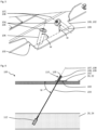
- Figure 1 shows a perspective view of an externally installed device 10 for cooling and/or heating a medium, connected to a foundation 20 inclined relative to the horizontal 1, here an inclined roof surface.
- the connection system 100 for connecting the device 10 to the foundation 20 is covered under a cover 12 (see for details Figures 2 to 6 ).
- Figure 2 shows a perspective view of parts of a connection system 100, in particular the support element 102 connected or connectable to the device 10, for connecting the device 10 to the foundation 20, which are visible above/outside a foundation surface 22.
- the device 10, not shown, would be as in Figure 1 above the connection system 100, connected or connectable to it.
- connection system 100 is used to connect the device 10 to a foundation surface 22 that is inclined relative to the horizontal 1, shown here using the example of a roof surface.
- the connection system 100 includes a support element 102 that can be connected to the device 10 and is arranged on the roof surface 22.
- a connecting element 104 for connecting the support element 102 to the foundation 20 is in the Figures 3 and 6 shown. You can see six guide elements 106 connected to the support element 102 for receiving and guiding the connecting elements 104.
- Figure 3 shows a section through a connection system 100 and the associated foundation 20.
- the foundation 20 can be seen with a foundation surface 22 and a foundation core 24. Above the foundation surface 22, the support element 102 of the connection system 100 is arranged. The foundation surface 22 is spaced apart from the foundation core 24. A thermal insulation layer 2, for example for thermally insulating a roof space, is arranged in a space between the foundation surface 22 and the foundation core 24.
- the connection system 100 that can be connected to the device 10 overcomes this distance. The weight, operating and disruptive forces on the part of the device 10 are introduced into the foundation core 24 for a permanently reliable and secure connection.
- the connection system 100 has four connecting elements 104 visible here, for example in the form of screws 104.
- the two middle connecting elements 104 show an oblique angle W with respect to the foundation surface 22. But the two outer connecting elements 104 also have an oblique angle W with respect to the foundation surface 22, but this inclination runs in a plane perpendicular to the viewing plane and is therefore not in this view recognizable.
- a length of the connecting element 104 is based on the distance between the foundation surface 22 and the foundation core 24 and on the angle W between the connecting element 104 and the foundation surface 22.
- the connecting elements 104 are each in a guide element (106, see details Figures 4 to 6 ) guided. The angle W of the connecting element 104 results from the angle of the guide element 106.
- the connecting element 104 comes during assembly from the support element 102 through the guide element 106 to the foundation core 24 without or with only with the slightest angular deviation and hits the target connection point precisely. This becomes particularly important if the foundation core 24 is a narrow supporting beam that should be connected as precisely as possible in the middle of the beam.
- the angle W between the connecting element 104 or guide element 106 on the one hand and the foundation surface 22 on the other hand corresponds to the angle W between the guide element 106 and the support surface 103 of the support element 102.
- connection system 100 can have a further connecting element 112, which is arranged or can be arranged in or on the foundation 20, in particular the foundation core 24, in particular a nut thread and/or a screw nut, as a counterpart to the connecting element 104.
- FIG 4 shows an enlarged view of detail IV of the connection system 100 in Figure 2 .
- the section of the support element 102 of the connection system 100 shown has the support surface 103 on its underside, which is hidden here, for resting on the foundation surface 22.
- the connection system 100 comprises a guide element 106 - in particular rigidly connected to the support element 102 - for receiving and guiding the connecting element 104, the guide element 106 only allowing a translational movement of the connecting element 104 in the direction of a guide axis 107 and/or a rotational movement about the guide axis 107.
- a head 105 in particular a screw head 105, can be seen here.
- the guide element 106 is designed like a sleeve and has a longitudinal extent, this longitudinal extent defining a longitudinal axis 108 which includes an angle W with a support surface 103 of the support element 102, the angle W assuming a value of 60 °.
- FIG. 5 shows a perspective view of detail V of the connection system 100 in Figure 2 .
- the section of the support element 102 of the connection system 100 shown has the support surface 103 on its underside, which is hidden here, for resting on the foundation surface 22.
- the Connection system 100 comprises two guide elements 106 - in particular rigidly connected to the support element 102 - for receiving and guiding one connecting element 104, wherein the guide element 106 only allows a translational movement of the connecting element 104 in the direction of a guide axis 107 and / or a rotational movement about the guide axis 107.
- the connecting elements 104 only one head 105, in particular a screw head 105, can be seen here.
- the guide element 106 is designed like a sleeve and has a longitudinal extent, this longitudinal extent defining a longitudinal axis 108 which includes an angle W with a support surface 103 of the support element 102, the angle W assuming a value of 60 °.
- Figure 6 shows a longitudinal section through a connection system 100 that is connected or can be connected to a device 10 (not shown here).
- the connection system 100 comprises a support element 102 arranged on a foundation surface 22 and a connecting element 104 for connecting the support element 102 to the foundation 20.
- the connection system 100 is designed to connect the device 10 (not shown here, see Figure 1 ) with the foundation core 24 arranged at a distance from the foundation surface 22.
- the connection system 100 includes a guide element 106 for receiving and guiding the connection element 104, wherein the guide element 106 only allows a translational movement of the connection element 104 in the direction of a guide axis 107 and/or a rotational movement about the guide axis 107.
- the guide element 106 is rigidly connected to the support element 102, so that there is no unwanted angular adjustment of the guide element 106 in relation to the support element 102 during production, assembly and / or operation of the connection system 100.
- the guide element 106 is designed like a sleeve and has a longitudinal extent, this longitudinal extent defining a longitudinal axis 108 which runs essentially along the guide axis 107.
- the guide element 106 comprises a tube section 109 and has a through opening 110 running longitudinally through the tube section 109, wherein the Through opening 110 is designed to receive and guide the connecting element 104.
- the guide element 106 is placed obliquely on the support element 102, and the pipe section 109 has an oblique end face.
- the longitudinal axis 108 of the guide element 106 forms an angle W with the support surface 103 of the support element 102, the angle W having a value of 60°.
- the connecting element 104 is bolt-shaped, for example as a screw 104 with a screw head 105.
- the connection system 100 comprises a further connection element 112, here a screw nut 112, as a counterpart to the connection element 104, arranged in the foundation core 24.
Landscapes
- Engineering & Computer Science (AREA)
- Chemical & Material Sciences (AREA)
- Combustion & Propulsion (AREA)
- Mechanical Engineering (AREA)
- General Engineering & Computer Science (AREA)
- Architecture (AREA)
- Civil Engineering (AREA)
- Structural Engineering (AREA)
- Joining Of Building Structures In Genera (AREA)
- Roof Covering Using Slabs Or Stiff Sheets (AREA)
- Connection Of Plates (AREA)
Abstract
Description
- The activity leading to this application has received funding from the European Institute of Innovation and Technology (EIT) under grant agreement No EIT/EIT InnoEnergy/SGA2018. This European body receives support from the European Union's the Horizon 2020 research and innovation programme.
- Aus der
EP 0 653 227 B1 ist eine Vorrichtung zum lösbaren Befestigen eines Tores auf einem Sportfeld bekannt. - Es ist Aufgabe der Erfindung, ein verbessertes Verbindungssystem zum Verbinden einer Vorrichtung zum Kühlen und/oder Erwärmen eines Mediums mit einem Fundament bereitzustellen.
- Die Erfindung geht aus von einem Verbindungssystem zum Verbinden einer Vorrichtung zum Kühlen und/oder Erwärmen eines Mediums mit einem Fundament, insbesondere einem gegenüber einer Horizontalen geneigten Fundament wie eine Dachfläche.
- Das Verbindungssystem weist zumindest ein mit der Vorrichtung verbundenes oder verbindbares Auflageelement zum Anordnen an einer Fundamentoberfläche und zumindest ein Verbindungselement zum Verbinden des Auflageelements mit dem Fundament auf.
- Es wird vorgeschlagen, zumindest ein Führungselement zum Aufnehmen und Führen des Verbindungselements vorzusehen, wobei das Führungselement nur eine Translationsbewegung des Verbindungselements in Richtung einer Führungsachse und/oder eine Rotationsbewegung um die Führungsachse zulässt.
- Unter einem Verbindungssystem soll in diesem Zusammenhang insbesondere ein System zum - insbesondere lösbaren - Anordnen und/oder Verbinden und/oder Fixieren zumindest zweier Bauteile zueinander beziehungsweise miteinander oder aneinander verstanden werden, insbesondere zum dauerhaften Verbleib in der Verbindung. Bei den zu verbindenden Bauteilen soll es sich hier insbesondere um eine Vorrichtung und ein Fundament handeln. Insbesondere berühren sich die Bauteile dabei an einem Berührpunkt oder in einer Berührebene, wobei die Berührebene von drei oder mehr Berührpunkten aufgespannt gedacht werden kann. Zum Verbinden der Vorrichtung mit dem Fundament können ein oder mehrere Verbindungssysteme verwendet werden. Das Verbindungssystem ist insbesondere mit der Vorrichtung verbunden und/oder verbindbar. Unter einer Vorrichtung soll in diesem Zusammenhang insbesondere ein dem Bereich Heizungsbau, Klima- und Lüftungstechnik zugeordnetes Heizgerät, ein Kühlgerät, eine Wärmepumpe oder eine Luftwärmetauschvorrichtung oder eine Komponente davon verstanden werden. Insbesondere kann die Vorrichtung eine in einer Außenumgebung aufstellbare Außeneinheit einer Luftwärmepumpe oder eine Monoblock-Wärmepumpe sein. Die Vorrichtung kann in einer Außenumgebung eines Gebäudes, insbesondere auf einem Dach des Gebäudes, aufgestellt sein. Alternativ kann die Vorrichtung im Wesentlichen ebenerdig aufgestellt sein. Die Vorrichtung nutzt Luft aus der Außenumgebung als Wärmequelle und/oder Wärmesenke. Unter einem Medium soll hier insbesondere ein flüssiges und/oder gasförmiges Wärmeträgermedium oder ein, insbesondere verdampfbares/kondensierbares, Kältemittel verstanden werden. Unter einem Fundament soll hier insbesondere eine dauerhaft tragfähige Unterkonstruktion der Vorrichtung verstanden werden. Beispielsweise kann es sich dabei um eine Holz-, Beton- oder Kunststoff-Unterkonstruktion in Balken-, Bohlen- oder Plattenbauweise handeln. Unter einem gegenüber einer Horizontalen geneigten Fundament soll hier insbesondere ein Fundament verstanden werden, dessen Berührpunkte oder Berührebene mit der Vorrichtung nicht in einer horizontalen Ebene liegen. Beispielsweise kann ein Dach oder eine Dachfläche eine solch geneigtes Fundament darstellen. Unter einer Fundamentoberfläche soll hier insbesondere die der Vorrichtung zugewandte Oberfläche des Fundaments verstanden werden, in der beispielsweise auch die Berührpunkte oder die Berührebene liegt. Die Fundamentoberfläche ist dazu ausgebildet, insbesondere Druck- und/oder Scherkräfte aus der Verbindung aufzunehmen. Die Fundamentoberfläche ist insbesondere nicht so belastbar ausgebildet wie der Fundamentkern. Unter einem Fundamentkern soll hier insbesondere ein zur Einleitung von Verbindungskräften, insbesondere Druck-, Zug-, Scher- und/oder Torsionskräften, belastbarer Fundamentabschnitt verstanden werden. Unter einem Auflageelement soll hier insbesondere ein mit der Vorrichtung, insbesondere ein mit einem Gehäuse oder einer Stützstruktur der Vorrichtung, integriert ausgebildetes Element verstanden werden. Alternativ kann das Auflageelement auch ein separat von der Vorrichtung ausgebildetes Element sein. Das Auflageelement kann nach Art eines Flansches, eines Rahmens, eines Tragwerks oder einer Fußplatte ausgebildet sein. Das Auflageelement kann insbesondere den Berührpunkt oder die Berührebene der Vorrichtung gegenüber dem Fundament ausbilden. Unter einem Verbindungselement soll hier insbesondere ein die Verbindung und/oder Fixierung zwischen Vorrichtung und Fundament begründendes und/oder sicherndes Element verstanden werden, das insbesondere zur Übertragung von Druck-, Zug-, Scher- und/oder Torsionskräften geeignet ist. Unter einem Führungselement soll hier insbesondere ein Element verstanden werden, das das Verbindungselement zumindest teilweise aufnimmt und/oder führt und/oder abstützt, insbesondere so dass eine translatorische Vor/zurück-Bewegung entlang einer Führungsachse sowie eine Drehbewegung um die Führungsachse möglich sind. Andere translatorische Freiheitsgrade (quer zur Führungsachse) und rotatorische Freiheitsgrade (kippen um andere, quer zur Führungsachse stehende, Achsen) des Verbindungselements sind eingeschränkt, insbesondere blockiert. Unter einer Führungsachse soll hier insbesondere eine Raumachse verstanden werden, die durch ein bestimmungsgemäßes Zusammenwirken von Führungselement und Verbindungselement definiert wird.
- Mittels des erfindungsgemäßen Verbindungssystems kann eine dauerhaft sichere, leicht zu montierende Verbindung zwischen der Vorrichtung und dem Fundament hergestellt werden. Das Verbindungssystem ist vorteilhafterweise dazu geeignet, Kräfte zuverlässig aufzunehmen und sicher in das Fundament einzuleiten. Beispielsweise sind das eine Gewichtskraft der Vorrichtung, Betriebskräfte durch Start/Stopp und Vibrationen einer Maschine der Vorrichtung, sowie Störkräfte aus Wind und Erschütterungen in der Aufstellumgebung der Vorrichtung, jeweils insbesondere mit Druck-, Zug-, Scher- und/oder Torsionskomponenten. Insbesondere bei Außenaufstellung der Vorrichtung auf einem Dach eines Gebäudes können starke Windkräfte auf die Vorrichtung und die Verbindung mit dem Fundament einwirken. Weiter gewährleistet das Verbindungssystem und/oder das Führungselement, dass bei der Montage der Vorrichtung am Fundament das Verbindungselement sicher an einer Soll-Verbindungsstelle im/am Fundament platziert werden kann, da das Verbindungselement in einer Zielrichtung entlang der Führungsachse auf die Soll-Verbindungsstelle zugeschoben und dort fixiert werden kann.
- Bei einer bevorzugten Ausgestaltung ist das Führungselement starr mit dem Auflageelement verbunden.
- Insbesondere kann das Führungselement separat vom Auflageelement gefertigt und anschließend kraftschlüssig (beispielsweise verschraubt), formschlüssig (beispielsweise vernietet) oder stoffschlüssig (beispielsweise verschweißt, verlötet, verklebt) mit dem Auflageelement verbunden sein. Alternativ kann das Führungselement einteilig mit dem Auflageelement geformt, beispielsweise gefräst, gegossen oder spritzgegossen, sein. Die starre Verbindung gewährleistet insbesondere, dass die mögliche Translations- und Rotationsbewegung des Verbindungselements relativ zum Auflageelement geometrisch festgelegt ist.
- Bei einer weiteren bevorzugten Ausgestaltung ist das Führungselement hülsenartig ausgebildet und weist eine Längserstreckung auf, wobei diese Längserstreckung eine Längsachse definiert, die im Wesentlichen entlang der Führungsachse verläuft.
- Unter hülsenartig soll hier insbesondere in Form eines Hohlzylinders und/oder Rohrs verstanden werden. Das Führungselement weist eine Höhlung auf, die insbesondere dazu ausgebildet ist, das Verbindungselement aufzunehmen und zu führen. Die Längsachse beziehungsweise die Führungsachse fallen insbesondere mit der Zylinderlängsachse (Extrusionsachse) des Hohlzylinders zusammen.
- Unter einem Zylinder soll hier insbesondere ein allgemeiner Zylinder, vorteilhafterweise ein Kreiszylinder, verstanden werden.
- Bei einer weiteren bevorzugten Ausgestaltung umfasst das Führungselement einen Rohrabschnitt und weist eine längs durch den Rohrabschnitt verlaufende Durchgangsöffnung auf, wobei die Durchgangsöffnung dazu ausgebildet ist, das Verbindungselement aufzunehmen und zu führen.
- Unter einem Rohrabschnitt soll hier insbesondere ein Abschnitt von einem Rohr mit zylindrischer Längsbohrung verstanden werden. Der Rohrabschnitt weist insbesondere eine Schnittfläche im Wesentlichen senkrecht zu seiner Längsachse oder die Längsachse unter einem Winkel W im Bereich 20° bis 80°, bevorzugt 40° bis 60°, besonders bevorzugt 60°, schneidend auf.
- Bei einer weiteren bevorzugten Ausgestaltung schließt die Längsachse des Führungselements einen Winkel W mit einer Auflagefläche des Auflageelements ein, wobei der Winkel W einen Wert im Bereich 20° bis 80°, bevorzugt 40° bis 60°, besonders bevorzugt 60°, annimmt.
- Unter einer Auflagefläche des Auflageelements soll hier insbesondere die Berührebene des Auflageelements und/oder der Vorrichtung gegenüber dem Fundament verstanden werden.
- Bei dieser Ausgestaltung des Verbindungssystems wird das Verbindungselement unter einem Winkel W mit dem Fundament verbunden. So können die verschiedenen möglichen Kräfte, die bei der Verbindung und während der Betriebsdauer auftreten können, zuverlässig und sicher in das Fundament eingeleitet werden. Insbesondere können zwischen der Auflagefläche und der Fundamentoberfläche wirkende Scherkräfte in Druckkräfte auf die Fundamentoberfläche und Zugkräfte im Verbindungselement umgewandelt werden. Dies sorgt zusätzlich für eine dauerhaft stabile und sichere Aufstellung der Vorrichtung.
- Bei einer weiteren bevorzugten Ausgestaltung ist das Verbindungselement, insbesondere im Wesentlichen, bolzenförmig, insbesondere als Schraube oder Gewindestange, ausgebildet.
- Unter bolzenförmig soll hier insbesondere zylindrisch verstanden werden. Das bolzenförmige Verbindungselement kann leicht und sicher längsverschieblich entlang einer Führungsachse sowie rotierbar um die Führungsachse in dem Führungselement aufgenommen werden.
- Die einander zugeordneten Abmessungen, insbesondere Querabmessungen, des Verbindungselements (insbesondere ein Außendurchmesser) und des Führungselements (insbesondere ein Innendurchmesser der Durchgangsöffnung) sind nach Art einer Spielpassung mit geringem Spiel gewählt, so dass sich das Verbindungselement nur entlang der Führungsachse sowie rotierbar um die Führungsachse bewegt. In den anderen Richtungen sind nur kleinste Translations- und/oder Rotationsbewegungen möglich.
- Eine weitere bevorzugte Ausgestaltung weist ein weiteres Verbindungselement, insbesondere ein Muttergewinde und/oder eine Schraubenmutter, als Gegenstück zum Verbindungselement, insbesondere zur Anordnung im oder am Fundament, auf.
- Das weitere Verbindungselement kann einteilig mit dem Fundament, insbesondere Fundamentkern, ausgebildet sein.
- Das Verbindungselement kann so ausgebildet sein, dass es bei Montage der Verbindung das zugeordnete weitere Verbindungselement selbst erzeugt. Beispielsweise kann das als selbstschneidende Schraube ausgebildete Verbindungselement bei Montage das Muttergewinde in das Fundament schneiden.
- Alternativ kann das weitere Verbindungselement als separates Bauteil ausgebildet, jedoch im/am Fundament, insbesondere Fundamentkern, angeordnet und dort, insbesondere translatorisch und/oder rotatorisch, fixiert sein.
- Bei einer weiteren bevorzugten Ausgestaltung ist das Verbindungssystem, insbesondere das Verbindungselement, ausgebildet, eine Verbindung der Vorrichtung mit einem beabstandet zu der Fundamentoberfläche angeordneten Fundamentkern herzustellen.
- Als Fundamentkern kann insbesondere ein stabil verankertes Element des Fundaments wie beispielsweise ein Balken eines Fundamenttragwerks (beispielsweise ein Dachtragwerk) oder eine Hilfskonstruktion im/am Fundamenttragwerk dienen. Beispielsweise kann im/am Fundamenttragwerk eine Hilfskonstruktion, insbesondere aus Holzbalken, verankert sein, die an die Abmessungen des Verbindungssystems und/oder der Vorrichtung angepasst ist.
- Die Erfindung betrifft auch eine mit einem Fundament, insbesondere einem gegenüber einer Horizontalen geneigten Fundament wie eine Dachfläche, verbundene oder verbindbare Vorrichtung zum Kühlen und/oder Erwärmen eines Mediums, aufweisend ein Verbindungssystem nach einer der vorstehenden Beschreibungen. Eine solche Vorrichtung kann dauerhaft zuverlässig und sicher ihre Funktion erfüllen, da sie stabil mit dem Fundament verbunden ist.
- Weitere Ausgestaltungen und Vorteile ergeben sich aus der folgenden Zeichnungsbeschreibung. In der Zeichnung sind Ausführungsbeispiele der Erfindung dargestellt. Die Zeichnung, die Beschreibung und die Ansprüche enthalten zahlreiche Merkmale in Kombination. Der Fachmann wird die Merkmale zweckmäßigerweise auch einzeln betrachten und zu sinnvollen weiteren Kombinationen zusammenfassen. Es zeigen:
- Figur 1
- eine perspektivische Ansicht einer Vorrichtung zum Kühlen und/oder Erwärmen eines Mediums auf einem gegenüber einer Horizontalen geneigten Fundament
- Figur 2
- eine perspektivische Ansicht eines Verbindungssystems zum Verbinden einer Vorrichtung mit einem Fundament
- Figur 3
- einen Schnitt durch ein Verbindungssystem zum Verbinden einer Vorrichtung mit einem Fundament
- Figur 4
- eine perspektivische Ansicht eines Details eines Verbindungssystems
- Figur 5
- eine perspektivische Ansicht eines Details eines Verbindungssystems
- Figur 6
- einen Schnitt durch ein Verbindungssystem.
-
Figur 1 zeigt eine perspektivische Ansicht einer außenaufgestellten Vorrichtung 10 zum Kühlen und/oder Erwärmen eines Mediums, verbunden mit einem gegenüber der Horizontalen 1 geneigten Fundament 20, hier einer geneigten Dachfläche. Das Verbindungssystem 100 zum Verbinden der Vorrichtung 10 mit dem Fundament 20 ist unter einer Blende 12 verdeckt (Details sieheFiguren 2 bis 6 ). -
Figur 2 zeigt eine perspektivische Ansicht von Teilen eines Verbindungssystems 100, insbesondere das mit der Vorrichtung 10 verbundene oder verbindbare Auflageelement 102, zum Verbinden der Vorrichtung 10 mit dem Fundament 20, die oberhalb/außerhalb einer Fundamentoberfläche 22 sichtbar sind. Die nicht dargestellte Vorrichtung 10 würde sich wie inFigur 1 oberhalb des Verbindungssystems 100, mit diesem verbunden oder verbindbar, anschließen. - Das Verbindungssystem 100 dient zum Verbinden der Vorrichtung 10 mit einer gegenüber der Horizontalen 1 geneigten Fundamentoberfläche 22, hier am Beispiel einer Dachfläche dargestellt. Das Verbindungssystem 100 umfasst ein mit der Vorrichtung 10 verbindbares Auflageelement 102, welches an der Dachoberfläche 22 angeordnet ist. Ein Verbindungselement 104 zum Verbinden des Auflageelements 102 mit dem Fundament 20 ist in den
Figuren 3 und6 dargestellt. Zu erkennen sind sechs mit dem Auflageelement 102 verbundene Führungselemente 106 zum Aufnehmen und Führen der Verbindungselemente 104. -
Figur 3 zeigt einen Schnitt durch ein Verbindungssystem 100 und das damit verbundene Fundament 20. - Zu erkennen sind das Fundament 20 mit einer Fundamentoberfläche 22 und einem Fundamentkern 24. Oberhalb der Fundamentoberfläche 22 ist das Auflageelement 102 des Verbindungssystems 100 angeordnet. Die Fundamentoberfläche 22 ist von dem Fundamentkern 24 beabstandet. In einem Zwischenraum zwischen Fundamentoberfläche 22 und Fundamentkern 24 ist eine Wärmedämmschicht 2, beispielsweise zum Wärmedämmen eines Dachraums, angeordnet. Zur Verbindung einer hier nicht dargestellten Vorrichtung (10, siehe aber
Figur 1 ) mit dem Fundament 20 überwindet das mit der Vorrichtung 10 verbindbare Verbindungssystem 100 diesen Abstand. Die Gewichts-, Betriebs- und Störkräfte seitens der Vorrichtung 10 werden für eine dauerhaft zuverlässige und sichere Verbindung in den Fundamentkern 24 eingeleitet. Dazu weist das Verbindungssystem 100 vier hier sichtbare Verbindungselemente 104, beispielsweise in Form von Schrauben 104, auf. Die beiden mittleren Verbindungselemente 104 zeigen einen schrägen Winkel W gegenüber der Fundamentoberfläche 22. Aber auch die beiden äußeren Verbindungselemente 104 weisen einen schrägen Winkel W gegenüber der Fundamentoberfläche 22 auf, diese Schräge verläuft allerdings in einer Ebene senkrecht zur Betrachtungsebene und ist daher in dieser Ansicht nicht erkennbar. Eine Länge des Verbindungselements 104 orientiert sich an dem Abstand zwischen Fundamentoberfläche 22 und Fundamentkern 24 sowie an dem Winkel W zwischen Verbindungselement 104 und Fundamentoberfläche 22. Die Verbindungselemente 104 sind jeweils in einem Führungselement (106, Details sieheFiguren 4 bis 6 ) geführt. Der Winkel W des Verbindungselements 104 ergibt sich aus dem Winkel des Führungselements 106. Wegen der eng tolerierten Führung des Verbindungselements 104 im Führungselement 106 wird das Verbindungselement 104 bei der Montage von dem Auflageelement 102 kommend durch das Führungselement 106 bis zum Fundamentkern 24 ohne oder mit nur geringster Winkelabweichung geführt und trifft dort zielgenau auf die Soll-Verbindungsstelle. Das wird besonders wichtig, wenn der Fundamentkern 24 ein schmaler Tragwerkbalken ist, der möglichst genau in Balkenmitte verbunden werden soll. - Da die Auflagefläche 103 des Auflageelements 102 auf der Fundamentoberfläche 22 zu liegen kommt, stimmt der Winkel W zwischen Verbindungselement 104 beziehungsweise Führungselement 106 einerseits und Fundamentoberfläche 22 andererseits mit dem Winkel W zwischen Führungselement 106 und Auflagefläche 103 des Auflageelements 102 überein.
- Das Verbindungssystem 100 kann ein weiteres, im oder am Fundament 20, insbesondere Fundamentkern 24, angeordnetes beziehungsweise anordenbares Verbindungselement 112 aufweisen, insbesondere ein Muttergewinde und/oder eine Schraubenmutter, als Gegenstück zum Verbindungselement 104. Damit kann das Verbindungselement 104 besonders einfach und sicher in das Fundament 20 eingebracht werden.
-
Figur 4 zeigt eine vergrößerte Ansicht des Details IV des Verbindungssystems 100 inFigur 2 . Der gezeigte Ausschnitt des Auflageelements 102 des Verbindungssystems 100 weist an seiner hier verdeckten Unterseite die Auflagefläche 103 zur Auflage auf der Fundamentoberfläche 22 auf. Das Verbindungssystem 100 umfasst ein - insbesondere starr mit dem Auflageelement 102 verbundenes - Führungselement 106 zum Aufnehmen und Führen des Verbindungselements 104, wobei das Führungselement 106 nur eine Translationsbewegung des Verbindungselements 104 in Richtung einer Führungsachse 107 und/oder eine Rotationsbewegung um die Führungsachse 107 zulässt. Von dem Verbindungselement 104 ist hier lediglich ein Kopf 105, insbesondere ein Schraubenkopf 105, zu sehen. - Das Führungselement 106 ist hülsenartig ausgebildet und weist eine Längserstreckung auf, wobei diese Längserstreckung eine Längsachse 108 definiert, die einen Winkel W mit einer Auflagefläche 103 des Auflageelements 102 einschließt, wobei der Winkel W einen Wert von 60° annimmt.
-
Figur 5 zeigt eine perspektivische Ansicht des Details V des Verbindungssystems 100 inFigur 2 . Der gezeigte Ausschnitt des Auflageelements 102 des Verbindungssystems 100 weist an seiner hier verdeckten Unterseite die Auflagefläche 103 zur Auflage auf der Fundamentoberfläche 22 auf. Das Verbindungssystem 100 umfasst zwei - insbesondere starr mit dem Auflageelement 102 verbundene - Führungselemente 106 zum Aufnehmen und Führen jeweils eines Verbindungselements 104, wobei das Führungselement 106 nur eine Translationsbewegung des Verbindungselements 104 in Richtung einer Führungsachse 107 und/oder eine Rotationsbewegung um die Führungsachse 107 zulässt. Von den Verbindungselementen 104 ist hier lediglich ein Kopf 105, insbesondere ein Schraubenkopf 105, zu sehen. - Das Führungselement 106 ist hülsenartig ausgebildet und weist eine Längserstreckung auf, wobei diese Längserstreckung eine Längsachse 108 definiert, die einen Winkel W mit einer Auflagefläche 103 des Auflageelements 102 einschließt, wobei der Winkel W einen Wert von 60° annimmt.
-
Figur 6 zeigt einen Längsschnitt durch ein mit einer hier nicht dargestellten Vorrichtung 10 verbundenes oder verbindbares Verbindungssystem 100. - Das Verbindungssystem 100 umfasst ein an einer Fundamentoberfläche 22 angeordnetes Auflageelement 102 sowie ein Verbindungselement 104 zum Verbinden des Auflageelements 102 mit dem Fundament 20. Das Verbindungssystem 100 ist ausgebildet, eine Verbindung der Vorrichtung 10 (hier nicht dargestellt, siehe
Figur 1 ) mit dem beabstandet zu der Fundamentoberfläche 22 angeordneten Fundamentkern 24 herzustellen. Das Verbindungssystem 100 umfasst ein Führungselement 106 zum Aufnehmen und Führen des Verbindungselements 104, wobei das Führungselement 106 nur eine Translationsbewegung des Verbindungselements 104 in Richtung einer Führungsachse 107 und/oder eine Rotationsbewegung um die Führungsachse 107 zulässt. Das Führungselement 106 ist starr mit dem Auflageelement 102 verbunden, so dass es bei Fertigung, Montage und/oder Betrieb des Verbindungssystems 100 nicht zu einer ungewollten Winkelverstellung des Führungselements 106 in Bezug zum Auflageelement 102 kommt. Das Führungselement 106 ist hülsenartig ausgebildet und weist eine Längserstreckung auf, wobei diese Längserstreckung eine Längsachse 108 definiert, die im Wesentlichen entlang der Führungsachse 107 verläuft. Das Führungselement 106 umfasst einen Rohrabschnitt 109 und weist eine längs durch den Rohrabschnitt 109 verlaufende Durchgangsöffnung 110 auf, wobei die Durchgangsöffnung 110 dazu ausgebildet ist, das Verbindungselement 104 aufzunehmen und zu führen. Das Führungselement 106 ist schräg auf dem Auflageelement 102 aufgesetzt, dazu weist der Rohrabschnitt 109 eine schräge Stirnfläche auf. Die Längsachse 108 des Führungselements 106 schließt einen Winkel W mit der Auflagefläche 103 des Auflageelements 102 ein, wobei der Winkel W einen Wert von 60° hat. Das Verbindungselement 104 ist bolzenförmig, beispielsweise als Schraube 104 mit Schraubenkopf 105, ausgebildet. Das Verbindungssystem 100 umfasst ein weiteres Verbindungselement 112, hier eine Schraubenmutter 112, als Gegenstück zum Verbindungselement 104, angeordnet im Fundamentkern 24.
Claims (9)
- Verbindungssystem (100) zum Verbinden einer Vorrichtung (10) zum Kühlen und/oder Erwärmen eines Mediums mit einem Fundament (20), insbesondere einem gegenüber einer Horizontalen (1) geneigten Fundament (20) wie eine Dachfläche, aufweisend zumindest ein mit der Vorrichtung (10) verbundenes oder verbindbares Auflageelement (102) zum Anordnen an einer Fundamentoberfläche (22) und zumindest ein Verbindungselement (104) zum Verbinden des Auflageelements (102) mit dem Fundament (20), gekennzeichnet durch zumindest ein Führungselement (106) zum Aufnehmen und Führen des Verbindungselements (104), wobei das Führungselement (106) nur eine Translationsbewegung des Verbindungselements (104) in Richtung einer Führungsachse (107) und/oder eine Rotationsbewegung um die Führungsachse (107) zulässt.
- Verbindungssystem (100) nach Anspruch 1,
dadurch gekennzeichnet, dass das Führungselement (106) starr mit dem Auflageelement (102) verbunden ist. - Verbindungssystem (100) nach Anspruch 1 oder 2,
dadurch gekennzeichnet, dass das Führungselement (106) hülsenartig ausgebildet ist und eine Längserstreckung aufweist, wobei diese Längserstreckung eine Längsachse (108) definiert, die im Wesentlichen entlang der Führungsachse (107) verläuft. - Verbindungssystem (100) nach einem der vorstehenden Ansprüche,
dadurch gekennzeichnet, dass das Führungselement (106) einen Rohrabschnitt (109) umfasst und eine längs durch den Rohrabschnitt (109) verlaufende Durchgangsöffnung (110) aufweist, wobei die Durchgangsöffnung (110) dazu ausgebildet ist, das Verbindungselement (104) aufzunehmen und zu führen. - Verbindungssystem (100) nach einem der vorstehenden Ansprüche,
dadurch gekennzeichnet, dass das Führungselement (106) hülsenartig ausgebildet ist und eine Längserstreckung aufweist, wobei diese Längserstreckung eine Längsachse (108) definiert, die einen Winkel W mit einer Auflagefläche (103) des Auflageelements (102) einschließt, wobei der Winkel W einen Wert im Bereich 20° bis 80°, bevorzugt 40° bis 60°, besonders bevorzugt 60°, annimmt. - Verbindungssystem (100) nach einem der vorstehenden Ansprüche,
dadurch gekennzeichnet, dass das Verbindungselement (104) bolzenförmig, insbesondere als Schraube oder Gewindestange, ausgebildet ist. - Verbindungssystem (100) nach einem der vorstehenden Ansprüche,
gekennzeichnet durch ein weiteres Verbindungselement (112), insbesondere ein Muttergewinde und/oder eine Schraubenmutter, als Gegenstück zum Verbindungselement (104), insbesondere zur Anordnung im oder am Fundament (20). - Verbindungssystem (100) nach einem der vorstehenden Ansprüche,
dadurch gekennzeichnet, dass das Verbindungssystem (100), insbesondere mittels des Verbindungselements (104), ausgebildet ist, eine Verbindung der Vorrichtung (10) mit einem beabstandet zu der Fundamentoberfläche (22) angeordneten Fundamentkern (24) herzustellen. - Mit einem Fundament (20), insbesondere einem gegenüber einer Horizontalen (1) geneigten Fundament (20), verbundene oder verbindbare Vorrichtung (10) zum Kühlen und/oder Erwärmen eines Mediums, aufweisend ein Verbindungssystem (100) nach einem der vorstehenden Ansprüche.
Applications Claiming Priority (1)
| Application Number | Priority Date | Filing Date | Title |
|---|---|---|---|
| DE102022204681.1A DE102022204681A1 (de) | 2022-05-13 | 2022-05-13 | Verbindungssystem zum Verbinden einer Vorrichtung zum Kühlen und/oder Erwärmen eines Mediums mit einem Fundament |
Publications (2)
| Publication Number | Publication Date |
|---|---|
| EP4276369A1 true EP4276369A1 (de) | 2023-11-15 |
| EP4276369B1 EP4276369B1 (de) | 2025-07-09 |
Family
ID=86328926
Family Applications (1)
| Application Number | Title | Priority Date | Filing Date |
|---|---|---|---|
| EP23171254.8A Active EP4276369B1 (de) | 2022-05-13 | 2023-05-03 | Verbindungssystem zum verbinden einer vorrichtung zum kühlen und/oder erwärmen eines mediums mit einem fundament |
Country Status (2)
| Country | Link |
|---|---|
| EP (1) | EP4276369B1 (de) |
| DE (1) | DE102022204681A1 (de) |
Citations (5)
| Publication number | Priority date | Publication date | Assignee | Title |
|---|---|---|---|---|
| EP0653227B1 (de) | 1993-11-08 | 1997-05-21 | Pierre Boutier | Vorrichtung zur lösbaren Befestigung eines Tores auf einem Sportfeld |
| JP2013177789A (ja) * | 2012-02-29 | 2013-09-09 | Sekisui House Ltd | 屋上設備機器設置用架台の取付装置及び取付方法 |
| EP3092350B1 (de) * | 2013-12-13 | 2019-04-17 | Jobdog, LLC | Schienenloses dachmontagesystem |
| US10840850B1 (en) * | 2016-08-16 | 2020-11-17 | Moti Atia | Mounting apparatus to secure solar panel rails to asphalt shingle roofs |
| EP3940301A1 (de) * | 2020-07-16 | 2022-01-19 | Robert Bosch GmbH | Montagevorrichtung für eine gebäudeversorgungsvorrichtung |
-
2022
- 2022-05-13 DE DE102022204681.1A patent/DE102022204681A1/de active Pending
-
2023
- 2023-05-03 EP EP23171254.8A patent/EP4276369B1/de active Active
Patent Citations (5)
| Publication number | Priority date | Publication date | Assignee | Title |
|---|---|---|---|---|
| EP0653227B1 (de) | 1993-11-08 | 1997-05-21 | Pierre Boutier | Vorrichtung zur lösbaren Befestigung eines Tores auf einem Sportfeld |
| JP2013177789A (ja) * | 2012-02-29 | 2013-09-09 | Sekisui House Ltd | 屋上設備機器設置用架台の取付装置及び取付方法 |
| EP3092350B1 (de) * | 2013-12-13 | 2019-04-17 | Jobdog, LLC | Schienenloses dachmontagesystem |
| US10840850B1 (en) * | 2016-08-16 | 2020-11-17 | Moti Atia | Mounting apparatus to secure solar panel rails to asphalt shingle roofs |
| EP3940301A1 (de) * | 2020-07-16 | 2022-01-19 | Robert Bosch GmbH | Montagevorrichtung für eine gebäudeversorgungsvorrichtung |
Also Published As
| Publication number | Publication date |
|---|---|
| DE102022204681A1 (de) | 2023-11-16 |
| EP4276369B1 (de) | 2025-07-09 |
Similar Documents
| Publication | Publication Date | Title |
|---|---|---|
| EP2614002B1 (de) | Befestigungseinrichtung | |
| EP0874176B1 (de) | Energieabsorberelement | |
| EP1978177B1 (de) | Abstandshalter zur Befestigung eines Halteelementes in einer Wandung | |
| DE3420696C1 (de) | Klemmbeschlag für die Befestigung und/oder Verbindung von Glasscheiben, insbesondere für Fassadenplatten aus Einscheibensicherheitsglas | |
| DE102010061139B4 (de) | Wärmebrückenfreier Adapter mit einer Anschlusseinheit zur Befestigung von Gegenständen an Wänden sowie ein Verfahren zur Befestigung von Gegenständen mit einem wärmebrückenfreien Adapter an Wänden | |
| EP2060699B1 (de) | Halterung für Verkleidungselemente bzw. eine Unterkonstruktion für Verkleidungselemente | |
| DE102013101422B3 (de) | Montagesystem zum Abstützen, Befestigen und Positionieren von Bauelementen | |
| EP4276369A1 (de) | Verbindungssystem zum verbinden einer vorrichtung zum kühlen und/oder erwärmen eines mediums mit einem fundament | |
| EP2236693B1 (de) | Wärmegedämmte Halterung für Verkleidungselemente | |
| EP0067970B1 (de) | Befestigungsvorrichtung für Fassadenelemente an einer Gebäudeaussenwand | |
| DE102018103565A1 (de) | Vorrichtung zur Sicherung von Personen gegen Absturz | |
| DE2109812B2 (de) | Halter zum elastischen Befestigen von Vorsatzplatten an Wänden oder Fußböden in Räumen | |
| EP3315679B1 (de) | Verbindungssystem | |
| DE102010020278B4 (de) | Vorrichtung zur Bereitstellung eines Befestigungspunktes an einem Profilelement | |
| EP3144448A1 (de) | Montageplatte zur befestigung eines bauteils an einer wand | |
| DE4011066A1 (de) | Anzugsbolzen fuer einbau von blockholzwandkonstruktionen | |
| EP2594718B1 (de) | Vorrichtung zum Fixieren eines Baukörpers in einer Gebäudeöffnung | |
| EP1659229B1 (de) | Montagefuss und Sanitärelement | |
| DE19725381A1 (de) | Beschlag zum Befestigen an Platten oder dergleichen, insbesondere Glasscheiben | |
| EP3348723B1 (de) | Überbrückungselement zur verbindung von bauelementen | |
| DE202020103389U1 (de) | Anschlussvorrichtung zum Befestigen an einem Hohlprofil sowie Stabilisierungsset und Stabilisierungsanordnung | |
| EP3196527B1 (de) | Stützanordnung | |
| AT511097A4 (de) | Isolierte befestigungsvorrichtung | |
| DE19854162A1 (de) | Schwingungsdämpfende Hülse mit körperschallschluckenden Eigenschaften | |
| EP2369089A1 (de) | Verbindungseinrichtung zur Verbindung einer Wand mit einem Fassadenelement oder mit einem Fassadenelementhalter |
Legal Events
| Date | Code | Title | Description |
|---|---|---|---|
| PUAI | Public reference made under article 153(3) epc to a published international application that has entered the european phase |
Free format text: ORIGINAL CODE: 0009012 |
|
| STAA | Information on the status of an ep patent application or granted ep patent |
Free format text: STATUS: THE APPLICATION HAS BEEN PUBLISHED |
|
| AK | Designated contracting states |
Kind code of ref document: A1 Designated state(s): AL AT BE BG CH CY CZ DE DK EE ES FI FR GB GR HR HU IE IS IT LI LT LU LV MC ME MK MT NL NO PL PT RO RS SE SI SK SM TR |
|
| STAA | Information on the status of an ep patent application or granted ep patent |
Free format text: STATUS: REQUEST FOR EXAMINATION WAS MADE |
|
| 17P | Request for examination filed |
Effective date: 20240515 |
|
| RBV | Designated contracting states (corrected) |
Designated state(s): AL AT BE BG CH CY CZ DE DK EE ES FI FR GB GR HR HU IE IS IT LI LT LU LV MC ME MK MT NL NO PL PT RO RS SE SI SK SM TR |
|
| GRAP | Despatch of communication of intention to grant a patent |
Free format text: ORIGINAL CODE: EPIDOSNIGR1 |
|
| STAA | Information on the status of an ep patent application or granted ep patent |
Free format text: STATUS: GRANT OF PATENT IS INTENDED |
|
| RIC1 | Information provided on ipc code assigned before grant |
Ipc: E04D 13/147 20060101ALI20250203BHEP Ipc: E04D 13/14 20060101ALI20250203BHEP Ipc: E04B 7/18 20060101ALI20250203BHEP Ipc: F24F 13/32 20060101ALI20250203BHEP Ipc: F24F 1/60 20110101AFI20250203BHEP |
|
| GRAS | Grant fee paid |
Free format text: ORIGINAL CODE: EPIDOSNIGR3 |
|
| INTG | Intention to grant announced |
Effective date: 20250219 |
|
| GRAA | (expected) grant |
Free format text: ORIGINAL CODE: 0009210 |
|
| STAA | Information on the status of an ep patent application or granted ep patent |
Free format text: STATUS: THE PATENT HAS BEEN GRANTED |
|
| AK | Designated contracting states |
Kind code of ref document: B1 Designated state(s): AL AT BE BG CH CY CZ DE DK EE ES FI FR GB GR HR HU IE IS IT LI LT LU LV MC ME MK MT NL NO PL PT RO RS SE SI SK SM TR |
|
| REG | Reference to a national code |
Ref country code: GB Ref legal event code: FG4D Free format text: NOT ENGLISH |
|
| REG | Reference to a national code |
Ref country code: CH Ref legal event code: EP |
|
| REG | Reference to a national code |
Ref country code: IE Ref legal event code: FG4D Free format text: LANGUAGE OF EP DOCUMENT: GERMAN |
|
| REG | Reference to a national code |
Ref country code: DE Ref legal event code: R096 Ref document number: 502023001297 Country of ref document: DE |
|
| REG | Reference to a national code |
Ref country code: NL Ref legal event code: FP |
|
| PG25 | Lapsed in a contracting state [announced via postgrant information from national office to epo] |
Ref country code: PT Free format text: LAPSE BECAUSE OF FAILURE TO SUBMIT A TRANSLATION OF THE DESCRIPTION OR TO PAY THE FEE WITHIN THE PRESCRIBED TIME-LIMIT Effective date: 20251110 |
|
| PG25 | Lapsed in a contracting state [announced via postgrant information from national office to epo] |
Ref country code: IS Free format text: LAPSE BECAUSE OF FAILURE TO SUBMIT A TRANSLATION OF THE DESCRIPTION OR TO PAY THE FEE WITHIN THE PRESCRIBED TIME-LIMIT Effective date: 20251109 |
|
| PG25 | Lapsed in a contracting state [announced via postgrant information from national office to epo] |
Ref country code: NO Free format text: LAPSE BECAUSE OF FAILURE TO SUBMIT A TRANSLATION OF THE DESCRIPTION OR TO PAY THE FEE WITHIN THE PRESCRIBED TIME-LIMIT Effective date: 20251009 |
|
| REG | Reference to a national code |
Ref country code: LT Ref legal event code: MG9D |
|
| PG25 | Lapsed in a contracting state [announced via postgrant information from national office to epo] |
Ref country code: FI Free format text: LAPSE BECAUSE OF FAILURE TO SUBMIT A TRANSLATION OF THE DESCRIPTION OR TO PAY THE FEE WITHIN THE PRESCRIBED TIME-LIMIT Effective date: 20250709 |
|
| PG25 | Lapsed in a contracting state [announced via postgrant information from national office to epo] |
Ref country code: HR Free format text: LAPSE BECAUSE OF FAILURE TO SUBMIT A TRANSLATION OF THE DESCRIPTION OR TO PAY THE FEE WITHIN THE PRESCRIBED TIME-LIMIT Effective date: 20250709 |
|
| PG25 | Lapsed in a contracting state [announced via postgrant information from national office to epo] |
Ref country code: GR Free format text: LAPSE BECAUSE OF FAILURE TO SUBMIT A TRANSLATION OF THE DESCRIPTION OR TO PAY THE FEE WITHIN THE PRESCRIBED TIME-LIMIT Effective date: 20251010 |
|
| PG25 | Lapsed in a contracting state [announced via postgrant information from national office to epo] |
Ref country code: SE Free format text: LAPSE BECAUSE OF FAILURE TO SUBMIT A TRANSLATION OF THE DESCRIPTION OR TO PAY THE FEE WITHIN THE PRESCRIBED TIME-LIMIT Effective date: 20250709 |
|
| PG25 | Lapsed in a contracting state [announced via postgrant information from national office to epo] |
Ref country code: LV Free format text: LAPSE BECAUSE OF FAILURE TO SUBMIT A TRANSLATION OF THE DESCRIPTION OR TO PAY THE FEE WITHIN THE PRESCRIBED TIME-LIMIT Effective date: 20250709 |
|
| PG25 | Lapsed in a contracting state [announced via postgrant information from national office to epo] |
Ref country code: PL Free format text: LAPSE BECAUSE OF FAILURE TO SUBMIT A TRANSLATION OF THE DESCRIPTION OR TO PAY THE FEE WITHIN THE PRESCRIBED TIME-LIMIT Effective date: 20250709 Ref country code: BG Free format text: LAPSE BECAUSE OF FAILURE TO SUBMIT A TRANSLATION OF THE DESCRIPTION OR TO PAY THE FEE WITHIN THE PRESCRIBED TIME-LIMIT Effective date: 20250709 |
|
| PG25 | Lapsed in a contracting state [announced via postgrant information from national office to epo] |
Ref country code: RS Free format text: LAPSE BECAUSE OF FAILURE TO SUBMIT A TRANSLATION OF THE DESCRIPTION OR TO PAY THE FEE WITHIN THE PRESCRIBED TIME-LIMIT Effective date: 20251009 |
|
| PG25 | Lapsed in a contracting state [announced via postgrant information from national office to epo] |
Ref country code: ES Free format text: LAPSE BECAUSE OF FAILURE TO SUBMIT A TRANSLATION OF THE DESCRIPTION OR TO PAY THE FEE WITHIN THE PRESCRIBED TIME-LIMIT Effective date: 20250709 |
|
| PG25 | Lapsed in a contracting state [announced via postgrant information from national office to epo] |
Ref country code: SM Free format text: LAPSE BECAUSE OF FAILURE TO SUBMIT A TRANSLATION OF THE DESCRIPTION OR TO PAY THE FEE WITHIN THE PRESCRIBED TIME-LIMIT Effective date: 20250709 |
|
| PG25 | Lapsed in a contracting state [announced via postgrant information from national office to epo] |
Ref country code: DK Free format text: LAPSE BECAUSE OF FAILURE TO SUBMIT A TRANSLATION OF THE DESCRIPTION OR TO PAY THE FEE WITHIN THE PRESCRIBED TIME-LIMIT Effective date: 20250709 |
|
| PG25 | Lapsed in a contracting state [announced via postgrant information from national office to epo] |
Ref country code: IT Free format text: LAPSE BECAUSE OF FAILURE TO SUBMIT A TRANSLATION OF THE DESCRIPTION OR TO PAY THE FEE WITHIN THE PRESCRIBED TIME-LIMIT Effective date: 20250709 |
|
| PG25 | Lapsed in a contracting state [announced via postgrant information from national office to epo] |
Ref country code: CZ Free format text: LAPSE BECAUSE OF FAILURE TO SUBMIT A TRANSLATION OF THE DESCRIPTION OR TO PAY THE FEE WITHIN THE PRESCRIBED TIME-LIMIT Effective date: 20250709 |
|
| PG25 | Lapsed in a contracting state [announced via postgrant information from national office to epo] |
Ref country code: SK Free format text: LAPSE BECAUSE OF FAILURE TO SUBMIT A TRANSLATION OF THE DESCRIPTION OR TO PAY THE FEE WITHIN THE PRESCRIBED TIME-LIMIT Effective date: 20250709 Ref country code: EE Free format text: LAPSE BECAUSE OF FAILURE TO SUBMIT A TRANSLATION OF THE DESCRIPTION OR TO PAY THE FEE WITHIN THE PRESCRIBED TIME-LIMIT Effective date: 20250709 |