EP4275507B1 - System zum aufhängen von geflügel - Google Patents
System zum aufhängen von geflügel Download PDFInfo
- Publication number
- EP4275507B1 EP4275507B1 EP23165278.5A EP23165278A EP4275507B1 EP 4275507 B1 EP4275507 B1 EP 4275507B1 EP 23165278 A EP23165278 A EP 23165278A EP 4275507 B1 EP4275507 B1 EP 4275507B1
- Authority
- EP
- European Patent Office
- Prior art keywords
- legs
- shackle
- poultry
- movable
- unit
- Prior art date
- Legal status (The legal status is an assumption and is not a legal conclusion. Google has not performed a legal analysis and makes no representation as to the accuracy of the status listed.)
- Active
Links
Images
Classifications
-
- A—HUMAN NECESSITIES
- A22—BUTCHERING; MEAT TREATMENT; PROCESSING POULTRY OR FISH
- A22C—PROCESSING MEAT, POULTRY, OR FISH
- A22C21/00—Processing poultry
-
- A—HUMAN NECESSITIES
- A22—BUTCHERING; MEAT TREATMENT; PROCESSING POULTRY OR FISH
- A22C—PROCESSING MEAT, POULTRY, OR FISH
- A22C15/00—Apparatus for hanging-up meat or sausages
-
- A—HUMAN NECESSITIES
- A22—BUTCHERING; MEAT TREATMENT; PROCESSING POULTRY OR FISH
- A22C—PROCESSING MEAT, POULTRY, OR FISH
- A22C21/00—Processing poultry
- A22C21/0007—Poultry shackles
-
- A—HUMAN NECESSITIES
- A22—BUTCHERING; MEAT TREATMENT; PROCESSING POULTRY OR FISH
- A22C—PROCESSING MEAT, POULTRY, OR FISH
- A22C21/00—Processing poultry
- A22C21/0038—Trussing poultry
-
- A—HUMAN NECESSITIES
- A22—BUTCHERING; MEAT TREATMENT; PROCESSING POULTRY OR FISH
- A22C—PROCESSING MEAT, POULTRY, OR FISH
- A22C21/00—Processing poultry
- A22C21/0046—Support devices
-
- A—HUMAN NECESSITIES
- A22—BUTCHERING; MEAT TREATMENT; PROCESSING POULTRY OR FISH
- A22C—PROCESSING MEAT, POULTRY, OR FISH
- A22C21/00—Processing poultry
- A22C21/0053—Transferring or conveying devices for poultry
Definitions
- the invention relates to a system for rehanging poultry which is suspended by the head in a first shackle of a first shackle conveyor to a second shackle of a second shackle conveyor in which the poultry is or will be suspended by the legs.
- WO2014/026695 discloses a method and system for suspending a bird by the legs from a shackle, wherein the following sequence of steps are executed: 1) bending at least one leg at the ankle joint so that the foot comes nearer to the breast of the bird, 2) inserting the leg in a shackle, 3) at least partially releasing the leg.
- the bending of the leg may be achieved by arranging an engagement member at the breast side of the leg to hinder a movement of the ankle joint towards the breast of the bird and using a carrier for forcing the foot towards the breast.
- the bending at the ankle joint results in a pull on tendons and muscles in the legs, which in turn causes the digits to come closer together and the foot to clench.
- WO00/41568 discloses in accordance with the preamble of claim 1 a system for rehanging poultry which is suspended by the head in a first shackle of a first shackle conveyor to a second shackle of a second shackle conveyor in which the poultry is or will be suspended by the legs, wherein the system comprises a leg positioning unit arranged to support the poultry at the legs while the poultry is maintained suspended by the head in the first shackle of the first shackle conveyor, and wherein the system comprises a movable takeover unit which is movable towards the second shackle of the second shackle conveyor for moving the legs of the poultry into the second shackle of the second shackle conveyor, wherein the movable takeover unit is arranged to be operational at least when the leg positioning unit supports the poultry at the legs.
- the system of WO2014/026695 does not provide this capability.
- the system of WO00/41568 lacks flexibility and is unsuited for high processing rates.
- the movable takeover unit is independently and separate from the leg positioning unit movable towards the second shackle of the second shackle conveyor and is arranged to act directly on the legs of the poultry to move the legs of the poultry into the second shackle of the second shackle conveyor.
- the system of the invention enables a complete automated method of rehanging wherein the poultry is first suspended by the head and is converted into being suspended by the legs, and wherein first a step of supporting the poultry at the legs is carried out while the poultry is maintained suspended by the head in the first shackle of the first shackle conveyor, then a further step of engaging the legs of the poultry is carried out with the movable takeover unit acting directly on the legs when the poultry is supported at the legs, and a step of moving the movable takeover unit that are directly acting on the legs towards the second shackle of the second shackle conveyor to move the legs of the poultry into the second shackle of the second shackle conveyor
- the leg positioning unit comprises a hook arranged to engage the legs of the poultry while suspended by the head.
- a hook is a well-known device in the poultry industry and is a robust instrument to perform the leg positioning operation.
- the hook of the leg positioning unit is arranged to follow an essentially circular path in approaching the legs to eventually engage the legs of the poultry, which circular path terminates at a position where the legs of the poultry extend obliquely or sideways away from where the poultry is suspended by the head.
- the legs of the poultry extend obliquely or sideways away they are in an appropriate position to be further engaged by the movable takeover unit, as detailed hereinafter.
- the movable takeover unit is arranged to engage the legs of the poultry in an upward movement of the takeover unit ending adjacent to where the leg positioning unit engages the legs of the poultry. Accordingly the takeover unit engages the legs of the poultry in a well-defined position, which is desirable in an automated operation as envisaged by the invention.
- leg positioning unit and/or the movable take-over unit engage the legs at or near the ankle at the ankle's front side, preferably above the ankle at a drum side of the legs. Accordingly a certain bending of the legs is caused which is helpful in correctly orienting the legs when the legs are later in the rehanging method moved by the takeover unit to the shackle from which the poultry will be suspended.
- the movable takeover unit is engaging the legs at a position which is more distant from the first shackle where the poultry is suspended by the head, than the distance of the leg positioning unit to the first shackle while said leg positioning unit is engaging the legs of the poultry.
- the movable takeover unit is provided with first slits for receiving therein the legs of the poultry.
- the movable takeover unit is provided with restricting elements for preventing removal of the legs from the first slits of the movable takeover unit. This secures that the poultry legs are not lost once the suspension of the poultry by the head is released, which causes the poultry to flip to a headdown orientation.
- the system is arranged to release the head from the first shackle after the movable takeover unit has engaged the legs of the poultry, and more preferably that the system is arranged to release the head from the first shackle after the restricting elements of the movable takeover unit are actuated to prevent removal of the legs from the first slits in which the legs of the poultry are received.
- the movable takeover unit is arranged to move the legs of the poultry towards the second shackle of the second shackle conveyor in an essentially horizontal motion. Mechanization of the motion is then easily accomplished.
- the system comprises the second conveyor which is provided with a series of second shackles.
- each second shackle is provided with essentially vertical slits for receiving and retaining the legs of the poultry, wherein the movable takeover unit is arranged to move downwards after the movable takeover unit with the legs of the poultry has been moved towards the second shackle of the second shackle conveyor, so as to move the legs for their retainment down into said essentially vertical slits of the second shackle.
- the movable take-over unit is arranged to move the feet extending from the legs above and beyond the upper horizontal rod, and then to move the legs downwards so that the feet engage the upper horizontal rod and the toes of the feet are moved into the second shackle prior to movement of the legs into said essentially vertical second slits of the second shackle.
- the movable takeover unit is arranged to move the legs in the downward movement into the second slits once the toes are securely arranged within said second shackle.
- the movable takeover unit is moved downwards after said movable takeover unit has moved the legs of the poultry above the second shackle of the second shackle conveyor such that the feet extending from the legs of the poultry project beyond the upper horizontal rod of said second shackle, so as to assume a proper starting position for subsequently moving the legs for their retainment down into the second shackle.
- the feet are first engaging the upper horizontal rod of the second shackle and by the continued downward movement of the takeover unit the toes of the feet are arranged to enter into the second shackle. In this way, the risk that the legs will eventually not move into the essentially vertical slits of the second shackle is reduced.
- a conventional second shackle can be used for suspending the poultry by the legs.
- Such a conventional shackle comprises a central vertical bar, wherein on a lower end of said central vertical bar and connected to said central vertical bar, two first rods diverge away from each other and connect to a lower horizontal rod distant from the central bar, wherein on opposite ends of the lower horizontal rod, said horizontal rod bends into two upwardly extending second rods that eventually connect to the central vertical bar, and wherein the two first rods and the two second rods delimit and define slits between the two first rods and the two second rods for receiving and retaining the legs of poultry suspended by the legs from the second shackle.
- a shackle wherein the two upwardly extending second rods merge into an upper horizontal rod distant from the lower horizontal rod, which upper horizontal rod is fixed in position at a predetermined distance from the central vertical bar. Accordingly it is easier to move the legs of the poultry into the second shackle when the movable takeover unit moves downwards following its motion towards the second shackle, during which downward movement the legs of the poultry are moved for their retainment down into the essentially vertical slits of the second shackle.
- the upper horizontal rod of the shackle is connected to the central vertical bar with an intermediate connection piece.
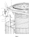
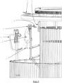
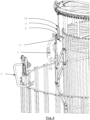
- Figure 1 shows poultry 1 suspended by the head 2 in a first shackle 3 of a first shackle conveyor.
- the system of the invention is designed to rehang this poultry 1 into a position in which it will eventually be suspended by the legs from a second shackle 4 of a second shackle conveyor.
- Figure 1 shows that the system comprises a leg positioning unit 5 in a not yet operational position.
- Figure 1 clearly shows that the leg positioning unit 5 comprises a hook 5' arranged to engage the legs 6 of the poultry 1 while suspended by the head 2.
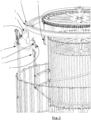
- leg positioning unit 5 is shown after it has become operational and has engaged the legs 6 of the poultry 1.
- Figure 2 shows that the leg positioning unit 5 is arranged to support the poultry 1 at the legs 6 while the poultry 1 is maintained suspended by the head 2 in the first shackle 3 of the first shackle conveyor.
- Figure 1 and figure 2 show that the leg positioning unit 5 is mounted on a hinge 8 which arranges that the hook 5' of the leg positioning unit 5 follows an essentially circular path in approaching the legs 6 of the poultry 1 wherein it eventually engages the legs 6 of the poultry 1. Said circular path terminates at a position where the legs 6 of the poultry 1 extend obliquely or sideways away from where the poultry 6 is suspended by the head 2. This last aspect is also shown in figure 2 .
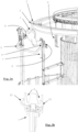
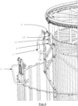
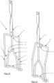
- a movable takeover unit 7 which is designed to operate directly on the legs 6 of the poultry 1 as is shown in figures 3A and 3B , is arranged to become operational after the leg positioning unit 5 supports the poultry 1 at the legs 6, as is shown in figure 2 . Further, as will be explained hereinafter with reference to figures 6 - 9 , at least this movable takeover unit 7 of the system is movable independent from the leg positioning unit 5 towards a second shackle 4 of the second shackle conveyor in order to move the legs 6 of the poultry 1 into such second shackle 4 of the second shackle conveyor.
- the movable takeover unit 7 is arranged to engage the legs 6 of the poultry 1 in an upward movement of the takeover unit 7 ending adjacent to where the leg positioning unit 5 engages the legs 6 of the poultry 1.
- the leg positioning unit 5 and/or the movable take-over unit 7 engage the legs 6 at or near the ankle at the ankle's front side, preferably above the ankle at a drum side of the legs 6, which is most clearly shown in figure 3A .
- the movable takeover unit 7 is engaging the legs 6 at a position which is more distant from the first shackle 3 where the poultry 1 is suspended by the head 2, than the distance of the leg positioning unit 5 to the first shackle 3 when said leg positioning unit 5 is engaging the legs 6 of the poultry 1.
- the movable takeover unit 7 is provided with slits 9 for receiving the legs 6 of the poultry 1.
- Figure 3B further shows that the movable takeover unit 7 is provided with restricting elements 10 for preventing removal of the legs 6 from the first slits 9 after the movable takeover unit 7 has engaged the legs 6 of the poultry 1 and received the legs 6 in the slits 9.
- These restricting elements 10 are activated to prevent removal of the legs 6 from the first slits 9 before the moment that the first shackle 3 from which the poultry 1 is suspended by the head 2 releases the head 2, causing the poultry 1 to flip over and become suspended by the legs 6 only from the movable take-over unit 7. This is depicted in figure 5 .
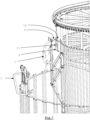
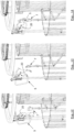
- the movable takeover unit 7 is arranged to move the legs 6 of the poultry 1 towards the second shackle 4 of the second shackle conveyor in a preferably essentially horizontal motion, which is illustrated by comparing the sequence of figures 5 - 7 .
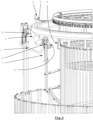
- Figure 6 depicts that the movable takeover unit 7 has approached the second shackle 4, wherein in the situation of figure 6 the feet of the legs 6 have reached a point lying above the second shackle 4.
- the second shackle 4 is provided with essentially vertical slits 11 for receiving and retaining the legs 6 of the poultry 1; this will hereinafter be further illustrated with reference to figures 10 and 11 .
- the movable takeover unit 7 is arranged to move downwards after the feet of the legs 6 have reached a point lying above the second shackle 4, as depicted in figure 6 wherein the movable takeover unit 7 has moved the legs 6 of the poultry 1 closely near to and above the second shackle 4 of the second shackle conveyor. With the subsequent downward movement of the movable takeover unit 7, the legs 6 of the poultry 1 are moved down such that the feet with the toes engage an upper bar 18 of the second shackle 4, prior to moving the toes to get into said second shackle 4 as depicted in figure 7 .
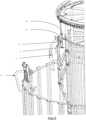
- FIG. 9 finally illustrates the movable takeover unit 7 immediately prior to the removal of the movable takeover unit 7, after which the poultry 1 will be entirely suspended by the legs 6 from the second shackle 4 of the second shackle conveyor.
- Such a conventional shackle 4 comprises a central vertical bar 12, wherein on a lower end 12' of said central vertical bar 12 and connected to said central vertical bar 12, two first rods 13, 14 diverge away from each other and connect to a lower horizontal rod 15 distant from the central bar 12, wherein on opposite ends of the lower horizontal rod 15, said horizontal rod 15 bends into two upwardly extending second rods 16, 17 that eventually connect to the central vertical bar 12, and wherein the two first rods 13, 14 and the two second rods 16, 17 delimit and define slits 11 between the two first rods 13, 14 and the two second rods 16, 17 for receiving and retaining the legs 6 of poultry 1 suspended by the legs 6 from this second shackle 4.
- a shackle according to the design as shown in figure 11 is used.
- the shackle according to figure 11 has the same features as the conventional shackle 4 which is shown in figure 10 , but has the additional and differentiating feature that the two upwardly extending second rods 16, 17 merge into an upper horizontal rod 18 distant from the lower horizontal rod 15, which upper horizontal rod 18 is fixed in position at a predetermined distance from the central vertical bar 12.
- the upper horizontal rod 18 is connected to the central vertical bar 12 with an intermediate connection piece 19.
- Embodiments of the present invention can include every combination of features that are disclosed herein independently from each other.
- the invention has been discussed in the foregoing with reference to an exemplary embodiment of the system of the invention, the invention is not restricted to this particular embodiment which can be varied in many ways without departing from the invention.
- the discussed exemplary embodiment shall therefore not be used to construe the appended claims strictly in accordance therewith.
- the embodiment is merely intended to explain the wording of the appended claims without intent to limit the claims to this exemplary embodiment.
- the scope of protection of the invention shall therefore be construed in accordance with the appended claims only, wherein a possible ambiguity in the wording of the claims shall be resolved using this exemplary embodiment.
- FIG. 12 - 14 shows several subsequent stages of movement of the leg positioning unit 5 and the movable takeover unit 7, wherein also the breast support 20 assumes different positions to assist in supporting the poultry 1 during the rehanging operation.
Landscapes
- Life Sciences & Earth Sciences (AREA)
- Engineering & Computer Science (AREA)
- Wood Science & Technology (AREA)
- Zoology (AREA)
- Food Science & Technology (AREA)
- Processing Of Meat And Fish (AREA)
- Catching Or Destruction (AREA)
Claims (16)
- System zum Umhängen von Geflügel (1), das am Kopf (2) in einem ersten Bügel (3) einer ersten Bügel-Fördereinrichtung aufgehängt ist, auf einen zweiten Bügel (4) einer zweiten Bügel-Fördereinrichtung, in der das Geflügel (1) an den Beinen (6) aufgehängt ist bzw. wird, wobei das System eine Beinpositioniereinheit (5) umfasst, die eingerichtet ist, um das Geflügel (1) an den Beinen (6) zu tragen, während das Geflügel (1) am Kopf (2) in dem ersten Bügel (3) der ersten Bügel-Fördereinrichtung aufgehängt bleibt, und wobei das System eine bewegliche Übernahmeeinheit (7) umfasst, die in Richtung des zweiten Bügels (4) der zweiten Bügel-Fördereinrichtung bewegbar ist, um die Beine (6) des Geflügels (1) in den zweiten Bügel (4) der zweiten Bügel-Fördereinrichtung zu bewegen, wobei die bewegliche Übernahmeeinheit (7) eingerichtet ist, um zumindest dann betreibbar zu sein, wenn die Beinpositioniereinheit (5) das Geflügel (1) an den Beinen (6) trägt, dadurch gekennzeichnet, dass die bewegliche Übernahmeeinheit (7) unabhängig und getrennt von der Beinpositioniereinheit (5) in Richtung des zweiten Bügels (4) der zweiten Bügel-Fördereinrichtung bewegbar ist und eingerichtet ist, um direkt auf die Beine (6) des Geflügels (1) zu wirken, um die Beine (6) des Geflügels (1) in den zweiten Bügel (4) der zweiten Bügel-Fördereinrichtung zu bewegen.
- System nach Anspruch 1, dadurch gekennzeichnet, dass die Beinpositioniereinheit (5) einen Haken (5') umfasst, der eingerichtet ist, um mit den Beinen (6) des Geflügels (1) in Eingriff zu kommen, während es am Kopf (2) aufgehängt ist.
- System nach Anspruch 2, dadurch gekennzeichnet, dass der Haken (5') der Beinpositioniereinheit (5) eingerichtet ist, um einer im Wesentlichen kreisförmigen Bahn zu folgen, wenn er sich den Beinen (6) nähert, um schließlich mit den Beinen (6) des Geflügels (1) in Eingriff zu kommen, wobei die kreisförmige Bahn an einer Position endet, an der sich die Beine (6) des Geflügels (1) schräg oder seitlich von der Stelle weg erstrecken, an der das Geflügel (1) am Kopf (2) aufgehängt ist.
- System nach einem der Ansprüche 1 - 3, dadurch gekennzeichnet, dass die bewegliche Übernahmeeinheit (7) eingerichtet ist, um mit den Beinen (6) des Geflügels (1) in einer Aufwärtsbewegung der Übernahmeeinheit (7) in Eingriff zu kommen, die benachbart zu der Stelle endet, an der die Beinpositioniereinheit (5) mit den Beinen (6) des Geflügels (1) in Eingriff kommt.
- System nach einem der Ansprüche 1 - 4, dadurch gekennzeichnet, dass die Beinpositioniereinheit (5) und/oder die bewegliche Übernahmeeinheit (7) mit den Beinen (6) des Geflügels (1) an oder nahe dem Knöchel an der Vorderseite des Knöchels in Eingriff kommen.
- System nach Anspruch 4 oder 5, dadurch gekennzeichnet, dass die bewegliche Übernahmeeinheit (7) mit den Beinen (6) an einer Position in Eingriff kommt, die weiter von dem ersten Bügel (3) entfernt ist, an dem das Geflügel (1) am Kopf (2) aufgehängt ist, als die Entfernung der Beinpositioniereinheit (5) zu dem ersten Bügel (3), wenn die Beinpositioniereinheit (5) mit den Beinen (6) des Geflügels (1) in Eingriff kommt.
- System nach einem der Ansprüche 1 - 6, dadurch gekennzeichnet, dass die bewegliche Übernahmeeinheit (7) mit ersten Schlitzen (9) zum Aufnehmen der Beine (6) des Geflügels (1) versehen ist.
- System nach Anspruch 7, dadurch gekennzeichnet, dass die bewegliche Übernahmeeinheit (7) mit Begrenzungselementen (10) versehen ist, um ein Entfernen der Beine (6) aus den ersten Schlitzen (9) zu verhindern.
- System nach einem der Ansprüche 1 - 8, dadurch gekennzeichnet, dass das System eingerichtet ist, um den Kopf (2) von dem ersten Bügel (3) zu lösen, nachdem die bewegliche Übernahmeeinheit (7) mit den Beinen (6) des Geflügels (1) in Eingriff gekommen ist.
- System nach Anspruch 8 und Anspruch 9, dadurch gekennzeichnet, dass das System eingerichtet ist, um den Kopf (2) von dem ersten Bügel (3) zu lösen, nachdem die Begrenzungselemente (10) der beweglichen Übernahmeeinheit (7) betätigt wurden, um ein Entfernen der Beine (6) aus den ersten Schlitzen (9) zu verhindern, in denen die Beine (6) des Geflügels (1) aufgenommen sind.
- System nach einem der Ansprüche 1 - 10, dadurch gekennzeichnet, dass die bewegliche Übernahmeeinheit (7) eingerichtet ist, um die Beine (6) des Geflügels (1) in einer im Wesentlichen horizontalen Bewegung in Richtung des zweiten Bügels (4) der zweiten Bügel-Fördereinrichtung zu bewegen.
- System nach einem der Ansprüche 1 - 11, ferner umfassend die zweite Bügel-Fördereinrichtung mit dem zweiten Bügel (4), in dem das Geflügel (1) an den Beinen (6) aufgehängt ist bzw. wird, dadurch gekennzeichnet, dass der zweite Bügel (4) mit im Wesentlichen vertikalen zweiten Schlitzen (11) zum Aufnehmen und Halten der Beine (6) des Geflügels (1) versehen ist, wobei die bewegliche Übernahmeeinheit (7) eingerichtet ist, um sich nach unten zu bewegen, nachdem die bewegliche Übernahmeeinheit (7) mit den Beinen (6) des Geflügels (1) in Richtung des zweiten Bügels (4) der zweiten Bügel-Fördereinrichtung bewegt wurde, um die Beine (6), um sie zu halten, nach unten in die im Wesentlichen vertikalen zweiten Schlitze (11) des zweiten Bügels (4) zu bewegen.
- System nach Anspruch 11 oder 12, wobei der zweite Bügel (4) eine obere horizontale Stange (18) umfasst, die von den zweiten Schlitzen (11) entfernt und über diesen angeordnet ist, dadurch gekennzeichnet, dass die bewegliche Übernahmeeinheit (7) eingerichtet ist, um die Füße, die sich von den Beinen (6) erstrecken, über die obere horizontale Stange (18) und darüber hinaus zu bewegen und dann die Beine (6) nach unten zu bewegen, so dass die Füße mit der oberen horizontalen Stange (18) in Eingriff kommen und die Zehen der Füße in den zweiten Bügel (4) bewegt werden, bevor die Beine (6) in die im Wesentlichen vertikalen zweiten Schlitze (11) des zweiten Bügels (4) bewegt werden.
- System nach Anspruch 13, dadurch gekennzeichnet, dass die bewegliche Übernahmeeinheit (7) eingerichtet ist, um die Beine (6) in der Abwärtsbewegung in die zweiten Schlitze (11) zu bewegen, sobald die Zehen in dem zweiten Bügel (4) angeordnet sind.
- System nach einem der Ansprüche 13 - 14, dadurch gekennzeichnet, dass der zweite Bügel (4) einen zentralen vertikalen Stab (12) umfasst, wobei an einem unteren Ende (12') des zentralen vertikalen Stabs (12) und mit dem zentralen vertikalen Stab (12) verbunden zwei erste Stangen (13, 14) voneinander weg auseinanderlaufen und mit einer unteren horizontalen Stange (15) verbunden sind, die von dem zentralen Stab (12) entfernt ist, wobei sich die horizontale Stange (15) an gegenüberliegenden Enden der unteren horizontalen Stange (15) in zwei sich nach oben erstreckende zweite Stangen (16, 17) biegt, die schließlich mit der zentralen vertikalen Stange (12) verbunden sind, und wobei die zwei ersten Stangen (13, 14) und die zwei zweiten Stangen (16, 17) Schlitze (11) zwischen den zwei ersten Stangen (13, 14) und den zwei zweiten Stangen (16, 17) begrenzen und definieren zum Aufnehmen und Halten der Beine (6) von Geflügel (1), das an den Beinen an dem zweiten Bügel (4) aufgehängt ist, wobei die zwei sich nach oben erstreckenden zweiten Stangen (16, 17) in die obere horizontale Stange (18) übergehen, die von der unteren horizontalen Stange (15) entfernt ist, wobei die obere horizontale Stange (18) in einer vorbestimmten Entfernung von der zentralen vertikalen Stange (12) in ihrer Position fixiert ist.
- System nach einem der Ansprüche 1 - 15, dadurch gekennzeichnet, dass das System einen Brustträger (20) zum Tragen des Geflügels (1) umfasst, bevor die Beinpositioniereinheit (5) das Geflügel (1) an den Beinen (6) trägt.
Applications Claiming Priority (1)
| Application Number | Priority Date | Filing Date | Title |
|---|---|---|---|
| NL2031855A NL2031855B1 (en) | 2022-05-13 | 2022-05-13 | A method and system for rehanging poultry, and a shackle for suspending the poultry |
Publications (2)
| Publication Number | Publication Date |
|---|---|
| EP4275507A1 EP4275507A1 (de) | 2023-11-15 |
| EP4275507B1 true EP4275507B1 (de) | 2025-01-29 |
Family
ID=82100483
Family Applications (1)
| Application Number | Title | Priority Date | Filing Date |
|---|---|---|---|
| EP23165278.5A Active EP4275507B1 (de) | 2022-05-13 | 2023-03-30 | System zum aufhängen von geflügel |
Country Status (9)
| Country | Link |
|---|---|
| US (1) | US12185730B2 (de) |
| EP (1) | EP4275507B1 (de) |
| JP (1) | JP7511050B2 (de) |
| CN (1) | CN117044765B (de) |
| BR (1) | BR102023009095A2 (de) |
| CA (1) | CA3199060A1 (de) |
| DK (1) | DK4275507T3 (de) |
| NL (1) | NL2031855B1 (de) |
| PL (1) | PL4275507T3 (de) |
Families Citing this family (1)
| Publication number | Priority date | Publication date | Assignee | Title |
|---|---|---|---|---|
| NL2037258B1 (en) | 2024-03-15 | 2025-09-26 | Meyn Food Processing Tech Bv | A system for hanging poultry |
Citations (7)
| Publication number | Priority date | Publication date | Assignee | Title |
|---|---|---|---|---|
| US3243840A (en) | 1964-03-24 | 1966-04-05 | Altenpohl W F | Leg and neck retaining poultry shackle |
| US5108345A (en) | 1991-03-25 | 1992-04-28 | Grover S. Harben, III | Apparatus and method for loading live fowl onto a conveyor |
| WO1994019957A1 (en) | 1993-03-01 | 1994-09-15 | Poutech A/S | A method for suspending live poultry by the legs and apparatus, catching means and shackle for carrying out the method |
| WO2000041568A2 (en) | 1999-01-15 | 2000-07-20 | Stork Pmt B.V. | Method and device for processing a slaughter animal |
| WO2011116774A1 (en) | 2010-03-26 | 2011-09-29 | Linco Food Systems A/S | Method and apparatus for suspending poultry to be slaughtered |
| WO2014026695A1 (en) | 2012-08-17 | 2014-02-20 | Linco Food Systems A/S | A method of suspending a bird from a shackle and an apparatus for suspending birds |
| JP2022087536A (ja) | 2020-12-01 | 2022-06-13 | 株式会社前川製作所 | 自動懸吊装置 |
Family Cites Families (10)
| Publication number | Priority date | Publication date | Assignee | Title |
|---|---|---|---|---|
| US3643293A (en) * | 1970-10-13 | 1972-02-22 | Pillsbury Co | Poultry transfer apparatus and method |
| US4283813A (en) * | 1979-12-03 | 1981-08-18 | Stork Gamco, Inc. | Poultry inspection apparatus and method |
| US4354296A (en) * | 1981-02-20 | 1982-10-19 | Robinson Ronald D | Method and apparatus for killing poultry |
| NL8400447A (nl) * | 1984-02-10 | 1985-09-02 | Stork Pmt | Inrichting voor het overbrengen van geslacht gevogelte. |
| US4964194A (en) * | 1989-04-24 | 1990-10-23 | L. J. Kessler | Apparatus and method for disjointing the thighbones of poultry carcasses |
| NL9200342A (nl) * | 1992-02-26 | 1993-09-16 | Meyn Maschf | Inrichting voor het aan de poten ophangen van gevogelte. |
| NL9201361A (nl) * | 1992-07-28 | 1994-02-16 | Meyn Maschf | Inrichting voor het uit de draaghaken van een hangtransporteur verwijderen van vogels. |
| US8641487B1 (en) * | 2012-12-12 | 2014-02-04 | WRH Holdings, LLC | Poultry wing segmenting system and method of use |
| NL2013532B1 (nl) * | 2014-09-26 | 2016-09-29 | Marel Stork Poultry Proc Bv | Inrichting en werkwijze voor het verwerken van slachtdieren en/of delen daarvan. |
| NL2021431B1 (en) * | 2018-08-06 | 2020-02-17 | Meyn Food Processing Tech Bv | Conveying assembly |
-
2022
- 2022-05-13 NL NL2031855A patent/NL2031855B1/en active
-
2023
- 2023-03-30 EP EP23165278.5A patent/EP4275507B1/de active Active
- 2023-03-30 DK DK23165278.5T patent/DK4275507T3/da active
- 2023-03-30 PL PL23165278.5T patent/PL4275507T3/pl unknown
- 2023-05-08 CA CA3199060A patent/CA3199060A1/en active Pending
- 2023-05-11 BR BR102023009095-8A patent/BR102023009095A2/pt unknown
- 2023-05-11 CN CN202310531493.0A patent/CN117044765B/zh active Active
- 2023-05-12 US US18/196,848 patent/US12185730B2/en active Active
- 2023-05-12 JP JP2023079070A patent/JP7511050B2/ja active Active
Patent Citations (7)
| Publication number | Priority date | Publication date | Assignee | Title |
|---|---|---|---|---|
| US3243840A (en) | 1964-03-24 | 1966-04-05 | Altenpohl W F | Leg and neck retaining poultry shackle |
| US5108345A (en) | 1991-03-25 | 1992-04-28 | Grover S. Harben, III | Apparatus and method for loading live fowl onto a conveyor |
| WO1994019957A1 (en) | 1993-03-01 | 1994-09-15 | Poutech A/S | A method for suspending live poultry by the legs and apparatus, catching means and shackle for carrying out the method |
| WO2000041568A2 (en) | 1999-01-15 | 2000-07-20 | Stork Pmt B.V. | Method and device for processing a slaughter animal |
| WO2011116774A1 (en) | 2010-03-26 | 2011-09-29 | Linco Food Systems A/S | Method and apparatus for suspending poultry to be slaughtered |
| WO2014026695A1 (en) | 2012-08-17 | 2014-02-20 | Linco Food Systems A/S | A method of suspending a bird from a shackle and an apparatus for suspending birds |
| JP2022087536A (ja) | 2020-12-01 | 2022-06-13 | 株式会社前川製作所 | 自動懸吊装置 |
Also Published As
| Publication number | Publication date |
|---|---|
| NL2031855B1 (en) | 2023-11-20 |
| BR102023009095A2 (pt) | 2023-11-28 |
| KR20230159303A (ko) | 2023-11-21 |
| US12185730B2 (en) | 2025-01-07 |
| EP4275507A1 (de) | 2023-11-15 |
| DK4275507T3 (da) | 2025-02-17 |
| CN117044765A (zh) | 2023-11-14 |
| CA3199060A1 (en) | 2023-11-13 |
| JP7511050B2 (ja) | 2024-07-04 |
| US20230363401A1 (en) | 2023-11-16 |
| PL4275507T3 (pl) | 2025-05-05 |
| JP2023168311A (ja) | 2023-11-24 |
| CN117044765B (zh) | 2025-08-19 |
Similar Documents
| Publication | Publication Date | Title |
|---|---|---|
| EP4275507B1 (de) | System zum aufhängen von geflügel | |
| EP0094724B1 (de) | Vorrichtung zum Ausnehmen von Schlachtgeflügel | |
| US5299976A (en) | Apparatus for retaining poultry | |
| US5643074A (en) | Method and apparatus for filleting the breast piece of slaughtered poultry | |
| DK1917859T3 (da) | Fremgangsmåde og indretning til behandling af en del af en slagtekrop af slagtet fjerkræ | |
| US6375560B1 (en) | Hanger for poultry | |
| KR20140120301A (ko) | 가금류를 처리하기 위한 방법 및 설비 | |
| CN112690317B (zh) | 对禽类腿或禽类腿的一部分去皮的去皮装置和方法 | |
| KR102921126B1 (ko) | 가금류를 다시 걸기 위한 방법 및 시스템, 그리고 가금류를 매달기 위한 쇠고리 | |
| US8592696B2 (en) | Game carcass hanger and releasable weighing apparatus | |
| EA044788B1 (ru) | Способ и система для перевешивания домашней птицы и подвеска для подвешивания домашней птицы | |
| EP2884848B1 (de) | Verfahren zum aufhängen von geflügel aus einm förderhacken und vorrichtung zum aufhängen von geflügel. | |
| US3156007A (en) | Poultry shackle | |
| AU699211B2 (en) | An arrangement for automated handling of a carcass and parts separated therefrom at machine-assisted cutting and boning | |
| US3507003A (en) | Poultry shackle | |
| AU2009222532A1 (en) | A method and device for de-gambrelling | |
| US3537127A (en) | Device for holding poultry for slaughtering and/or plucking | |
| CN106455593B (zh) | 一种用于将禽放置在适于被悬挂在钩环上的位置的方法和装置 | |
| US2846717A (en) | Fowl head holding and positioning apparatus | |
| CN116601090A (zh) | 悬垂轨道运输系统 | |
| EP2486801A1 (de) | Maschine zum Einführen oder Entfernen von Lebensmittelprodukten zwischen einem Paar Kompressionsgittern | |
| SU1055709A1 (ru) | Устройство дл навешивани и съема изделий | |
| CS224198B1 (cs) | Způsob automatického svěšování prasat, surových hovězích kůží a jiných podobných břemen | |
| JPS6251087B2 (de) | ||
| IT1267149B1 (it) | Macchina automatica e sistema a filo continuo per la legatura dei polli a mezzo trasportatore a catena con ganasce automatiche per la |
Legal Events
| Date | Code | Title | Description |
|---|---|---|---|
| PUAI | Public reference made under article 153(3) epc to a published international application that has entered the european phase |
Free format text: ORIGINAL CODE: 0009012 |
|
| STAA | Information on the status of an ep patent application or granted ep patent |
Free format text: STATUS: THE APPLICATION HAS BEEN PUBLISHED |
|
| AK | Designated contracting states |
Kind code of ref document: A1 Designated state(s): AL AT BE BG CH CY CZ DE DK EE ES FI FR GB GR HR HU IE IS IT LI LT LU LV MC ME MK MT NL NO PL PT RO RS SE SI SK SM TR |
|
| STAA | Information on the status of an ep patent application or granted ep patent |
Free format text: STATUS: REQUEST FOR EXAMINATION WAS MADE |
|
| 17P | Request for examination filed |
Effective date: 20240515 |
|
| RBV | Designated contracting states (corrected) |
Designated state(s): AL AT BE BG CH CY CZ DE DK EE ES FI FR GB GR HR HU IE IS IT LI LT LU LV MC ME MK MT NL NO PL PT RO RS SE SI SK SM TR |
|
| GRAP | Despatch of communication of intention to grant a patent |
Free format text: ORIGINAL CODE: EPIDOSNIGR1 |
|
| STAA | Information on the status of an ep patent application or granted ep patent |
Free format text: STATUS: GRANT OF PATENT IS INTENDED |
|
| INTG | Intention to grant announced |
Effective date: 20241009 |
|
| GRAS | Grant fee paid |
Free format text: ORIGINAL CODE: EPIDOSNIGR3 |
|
| GRAA | (expected) grant |
Free format text: ORIGINAL CODE: 0009210 |
|
| STAA | Information on the status of an ep patent application or granted ep patent |
Free format text: STATUS: THE PATENT HAS BEEN GRANTED |
|
| AK | Designated contracting states |
Kind code of ref document: B1 Designated state(s): AL AT BE BG CH CY CZ DE DK EE ES FI FR GB GR HR HU IE IS IT LI LT LU LV MC ME MK MT NL NO PL PT RO RS SE SI SK SM TR |
|
| P01 | Opt-out of the competence of the unified patent court (upc) registered |
Free format text: CASE NUMBER: APP_67538/2024 Effective date: 20241220 |
|
| REG | Reference to a national code |
Ref country code: GB Ref legal event code: FG4D |
|
| REG | Reference to a national code |
Ref country code: CH Ref legal event code: EP |
|
| REG | Reference to a national code |
Ref country code: DK Ref legal event code: T3 Effective date: 20250213 |
|
| REG | Reference to a national code |
Ref country code: DE Ref legal event code: R096 Ref document number: 602023001833 Country of ref document: DE |
|
| REG | Reference to a national code |
Ref country code: IE Ref legal event code: FG4D |
|
| REG | Reference to a national code |
Ref country code: NL Ref legal event code: FP |
|
| PGFP | Annual fee paid to national office [announced via postgrant information from national office to epo] |
Ref country code: DE Payment date: 20250327 Year of fee payment: 3 |
|
| PGFP | Annual fee paid to national office [announced via postgrant information from national office to epo] |
Ref country code: DK Payment date: 20250325 Year of fee payment: 3 |
|
| PGFP | Annual fee paid to national office [announced via postgrant information from national office to epo] |
Ref country code: AT Payment date: 20250417 Year of fee payment: 3 |
|
| PGFP | Annual fee paid to national office [announced via postgrant information from national office to epo] |
Ref country code: FR Payment date: 20250325 Year of fee payment: 3 |
|
| PG25 | Lapsed in a contracting state [announced via postgrant information from national office to epo] |
Ref country code: RS Free format text: LAPSE BECAUSE OF FAILURE TO SUBMIT A TRANSLATION OF THE DESCRIPTION OR TO PAY THE FEE WITHIN THE PRESCRIBED TIME-LIMIT Effective date: 20250429 |
|
| PG25 | Lapsed in a contracting state [announced via postgrant information from national office to epo] |
Ref country code: FI Free format text: LAPSE BECAUSE OF FAILURE TO SUBMIT A TRANSLATION OF THE DESCRIPTION OR TO PAY THE FEE WITHIN THE PRESCRIBED TIME-LIMIT Effective date: 20250129 |
|
| PGFP | Annual fee paid to national office [announced via postgrant information from national office to epo] |
Ref country code: PL Payment date: 20250306 Year of fee payment: 3 |
|
| PG25 | Lapsed in a contracting state [announced via postgrant information from national office to epo] |
Ref country code: ES Free format text: LAPSE BECAUSE OF FAILURE TO SUBMIT A TRANSLATION OF THE DESCRIPTION OR TO PAY THE FEE WITHIN THE PRESCRIBED TIME-LIMIT Effective date: 20250129 |
|
| REG | Reference to a national code |
Ref country code: LT Ref legal event code: MG9D |
|
| PG25 | Lapsed in a contracting state [announced via postgrant information from national office to epo] |
Ref country code: NO Free format text: LAPSE BECAUSE OF FAILURE TO SUBMIT A TRANSLATION OF THE DESCRIPTION OR TO PAY THE FEE WITHIN THE PRESCRIBED TIME-LIMIT Effective date: 20250429 Ref country code: IS Free format text: LAPSE BECAUSE OF FAILURE TO SUBMIT A TRANSLATION OF THE DESCRIPTION OR TO PAY THE FEE WITHIN THE PRESCRIBED TIME-LIMIT Effective date: 20250529 |
|
| REG | Reference to a national code |
Ref country code: AT Ref legal event code: MK05 Ref document number: 1762513 Country of ref document: AT Kind code of ref document: T Effective date: 20250129 |
|
| PG25 | Lapsed in a contracting state [announced via postgrant information from national office to epo] |
Ref country code: HR Free format text: LAPSE BECAUSE OF FAILURE TO SUBMIT A TRANSLATION OF THE DESCRIPTION OR TO PAY THE FEE WITHIN THE PRESCRIBED TIME-LIMIT Effective date: 20250129 |
|
| PG25 | Lapsed in a contracting state [announced via postgrant information from national office to epo] |
Ref country code: PT Free format text: LAPSE BECAUSE OF FAILURE TO SUBMIT A TRANSLATION OF THE DESCRIPTION OR TO PAY THE FEE WITHIN THE PRESCRIBED TIME-LIMIT Effective date: 20250529 Ref country code: LV Free format text: LAPSE BECAUSE OF FAILURE TO SUBMIT A TRANSLATION OF THE DESCRIPTION OR TO PAY THE FEE WITHIN THE PRESCRIBED TIME-LIMIT Effective date: 20250129 |
|
| PG25 | Lapsed in a contracting state [announced via postgrant information from national office to epo] |
Ref country code: BG Free format text: LAPSE BECAUSE OF FAILURE TO SUBMIT A TRANSLATION OF THE DESCRIPTION OR TO PAY THE FEE WITHIN THE PRESCRIBED TIME-LIMIT Effective date: 20250129 Ref country code: GR Free format text: LAPSE BECAUSE OF FAILURE TO SUBMIT A TRANSLATION OF THE DESCRIPTION OR TO PAY THE FEE WITHIN THE PRESCRIBED TIME-LIMIT Effective date: 20250430 |
|
| PG25 | Lapsed in a contracting state [announced via postgrant information from national office to epo] |
Ref country code: AT Free format text: LAPSE BECAUSE OF FAILURE TO SUBMIT A TRANSLATION OF THE DESCRIPTION OR TO PAY THE FEE WITHIN THE PRESCRIBED TIME-LIMIT Effective date: 20250129 |
|
| PG25 | Lapsed in a contracting state [announced via postgrant information from national office to epo] |
Ref country code: SE Free format text: LAPSE BECAUSE OF FAILURE TO SUBMIT A TRANSLATION OF THE DESCRIPTION OR TO PAY THE FEE WITHIN THE PRESCRIBED TIME-LIMIT Effective date: 20250129 |
|
| PG25 | Lapsed in a contracting state [announced via postgrant information from national office to epo] |
Ref country code: SM Free format text: LAPSE BECAUSE OF FAILURE TO SUBMIT A TRANSLATION OF THE DESCRIPTION OR TO PAY THE FEE WITHIN THE PRESCRIBED TIME-LIMIT Effective date: 20250129 |
|
| PG25 | Lapsed in a contracting state [announced via postgrant information from national office to epo] |
Ref country code: MC Free format text: LAPSE BECAUSE OF FAILURE TO SUBMIT A TRANSLATION OF THE DESCRIPTION OR TO PAY THE FEE WITHIN THE PRESCRIBED TIME-LIMIT Effective date: 20250129 |
|
| PG25 | Lapsed in a contracting state [announced via postgrant information from national office to epo] |
Ref country code: IT Free format text: LAPSE BECAUSE OF FAILURE TO SUBMIT A TRANSLATION OF THE DESCRIPTION OR TO PAY THE FEE WITHIN THE PRESCRIBED TIME-LIMIT Effective date: 20250129 |
|
| PG25 | Lapsed in a contracting state [announced via postgrant information from national office to epo] |
Ref country code: EE Free format text: LAPSE BECAUSE OF FAILURE TO SUBMIT A TRANSLATION OF THE DESCRIPTION OR TO PAY THE FEE WITHIN THE PRESCRIBED TIME-LIMIT Effective date: 20250129 Ref country code: CZ Free format text: LAPSE BECAUSE OF FAILURE TO SUBMIT A TRANSLATION OF THE DESCRIPTION OR TO PAY THE FEE WITHIN THE PRESCRIBED TIME-LIMIT Effective date: 20250129 |
|
| PG25 | Lapsed in a contracting state [announced via postgrant information from national office to epo] |
Ref country code: RO Free format text: LAPSE BECAUSE OF FAILURE TO SUBMIT A TRANSLATION OF THE DESCRIPTION OR TO PAY THE FEE WITHIN THE PRESCRIBED TIME-LIMIT Effective date: 20250129 |
|
| PG25 | Lapsed in a contracting state [announced via postgrant information from national office to epo] |
Ref country code: SK Free format text: LAPSE BECAUSE OF FAILURE TO SUBMIT A TRANSLATION OF THE DESCRIPTION OR TO PAY THE FEE WITHIN THE PRESCRIBED TIME-LIMIT Effective date: 20250129 |
|
| REG | Reference to a national code |
Ref country code: DE Ref legal event code: R026 Ref document number: 602023001833 Country of ref document: DE |
|
| PLBI | Opposition filed |
Free format text: ORIGINAL CODE: 0009260 |
|
| PLAX | Notice of opposition and request to file observation + time limit sent |
Free format text: ORIGINAL CODE: EPIDOSNOBS2 |
|
| PG25 | Lapsed in a contracting state [announced via postgrant information from national office to epo] |
Ref country code: LU Free format text: LAPSE BECAUSE OF NON-PAYMENT OF DUE FEES Effective date: 20250330 |
|
| 26 | Opposition filed |
Opponent name: MAREL POULTRY B.V. Effective date: 20251029 |
|
| REG | Reference to a national code |
Ref country code: BE Ref legal event code: MM Effective date: 20250331 |
|
| PG25 | Lapsed in a contracting state [announced via postgrant information from national office to epo] |
Ref country code: BE Free format text: LAPSE BECAUSE OF NON-PAYMENT OF DUE FEES Effective date: 20250331 |
|
| PG25 | Lapsed in a contracting state [announced via postgrant information from national office to epo] |
Ref country code: IE Free format text: LAPSE BECAUSE OF NON-PAYMENT OF DUE FEES Effective date: 20250330 |