EP4273464A2 - Mehrspuliger mikrokanalwärmetauscher und klimaanlage - Google Patents
Mehrspuliger mikrokanalwärmetauscher und klimaanlage Download PDFInfo
- Publication number
- EP4273464A2 EP4273464A2 EP22810694.4A EP22810694A EP4273464A2 EP 4273464 A2 EP4273464 A2 EP 4273464A2 EP 22810694 A EP22810694 A EP 22810694A EP 4273464 A2 EP4273464 A2 EP 4273464A2
- Authority
- EP
- European Patent Office
- Prior art keywords
- coil
- heat exchanger
- microchannel heat
- inlet
- outlet
- Prior art date
- Legal status (The legal status is an assumption and is not a legal conclusion. Google has not performed a legal analysis and makes no representation as to the accuracy of the status listed.)
- Granted
Links
Images


Classifications
-
- F—MECHANICAL ENGINEERING; LIGHTING; HEATING; WEAPONS; BLASTING
- F28—HEAT EXCHANGE IN GENERAL
- F28F—DETAILS OF HEAT-EXCHANGE AND HEAT-TRANSFER APPARATUS, OF GENERAL APPLICATION
- F28F9/00—Casings; Header boxes; Auxiliary supports for elements; Auxiliary members within casings
- F28F9/26—Arrangements for connecting different sections of heat-exchange elements, e.g. of radiators
-
- F—MECHANICAL ENGINEERING; LIGHTING; HEATING; WEAPONS; BLASTING
- F28—HEAT EXCHANGE IN GENERAL
- F28D—HEAT-EXCHANGE APPARATUS, NOT PROVIDED FOR IN ANOTHER SUBCLASS, IN WHICH THE HEAT-EXCHANGE MEDIA DO NOT COME INTO DIRECT CONTACT
- F28D1/00—Heat-exchange apparatus having stationary conduit assemblies for one heat-exchange medium only, the media being in contact with different sides of the conduit wall, in which the other heat-exchange medium is a large body of fluid, e.g. domestic or motor car radiators
- F28D1/02—Heat-exchange apparatus having stationary conduit assemblies for one heat-exchange medium only, the media being in contact with different sides of the conduit wall, in which the other heat-exchange medium is a large body of fluid, e.g. domestic or motor car radiators with heat-exchange conduits immersed in the body of fluid
- F28D1/04—Heat-exchange apparatus having stationary conduit assemblies for one heat-exchange medium only, the media being in contact with different sides of the conduit wall, in which the other heat-exchange medium is a large body of fluid, e.g. domestic or motor car radiators with heat-exchange conduits immersed in the body of fluid with tubular conduits
- F28D1/047—Heat-exchange apparatus having stationary conduit assemblies for one heat-exchange medium only, the media being in contact with different sides of the conduit wall, in which the other heat-exchange medium is a large body of fluid, e.g. domestic or motor car radiators with heat-exchange conduits immersed in the body of fluid with tubular conduits the conduits being bent, e.g. in a serpentine or zig-zag
- F28D1/0475—Heat-exchange apparatus having stationary conduit assemblies for one heat-exchange medium only, the media being in contact with different sides of the conduit wall, in which the other heat-exchange medium is a large body of fluid, e.g. domestic or motor car radiators with heat-exchange conduits immersed in the body of fluid with tubular conduits the conduits being bent, e.g. in a serpentine or zig-zag the conduits having a single U-bend
- F28D1/0476—Heat-exchange apparatus having stationary conduit assemblies for one heat-exchange medium only, the media being in contact with different sides of the conduit wall, in which the other heat-exchange medium is a large body of fluid, e.g. domestic or motor car radiators with heat-exchange conduits immersed in the body of fluid with tubular conduits the conduits being bent, e.g. in a serpentine or zig-zag the conduits having a single U-bend the conduits having a non-circular cross-section
-
- F—MECHANICAL ENGINEERING; LIGHTING; HEATING; WEAPONS; BLASTING
- F24—HEATING; RANGES; VENTILATING
- F24F—AIR-CONDITIONING; AIR-HUMIDIFICATION; VENTILATION; USE OF AIR CURRENTS FOR SCREENING
- F24F1/00—Room units for air-conditioning, e.g. separate or self-contained units or units receiving primary air from a central station
- F24F1/06—Separate outdoor units, e.g. outdoor unit to be linked to a separate room comprising a compressor and a heat exchanger
- F24F1/14—Heat exchangers specially adapted for separate outdoor units
-
- F—MECHANICAL ENGINEERING; LIGHTING; HEATING; WEAPONS; BLASTING
- F24—HEATING; RANGES; VENTILATING
- F24F—AIR-CONDITIONING; AIR-HUMIDIFICATION; VENTILATION; USE OF AIR CURRENTS FOR SCREENING
- F24F13/00—Details common to, or for air-conditioning, air-humidification, ventilation or use of air currents for screening
- F24F13/30—Arrangement or mounting of heat-exchangers
-
- F—MECHANICAL ENGINEERING; LIGHTING; HEATING; WEAPONS; BLASTING
- F28—HEAT EXCHANGE IN GENERAL
- F28D—HEAT-EXCHANGE APPARATUS, NOT PROVIDED FOR IN ANOTHER SUBCLASS, IN WHICH THE HEAT-EXCHANGE MEDIA DO NOT COME INTO DIRECT CONTACT
- F28D1/00—Heat-exchange apparatus having stationary conduit assemblies for one heat-exchange medium only, the media being in contact with different sides of the conduit wall, in which the other heat-exchange medium is a large body of fluid, e.g. domestic or motor car radiators
- F28D1/02—Heat-exchange apparatus having stationary conduit assemblies for one heat-exchange medium only, the media being in contact with different sides of the conduit wall, in which the other heat-exchange medium is a large body of fluid, e.g. domestic or motor car radiators with heat-exchange conduits immersed in the body of fluid
- F28D1/04—Heat-exchange apparatus having stationary conduit assemblies for one heat-exchange medium only, the media being in contact with different sides of the conduit wall, in which the other heat-exchange medium is a large body of fluid, e.g. domestic or motor car radiators with heat-exchange conduits immersed in the body of fluid with tubular conduits
- F28D1/0408—Multi-circuit heat exchangers, e.g. integrating different heat exchange sections in the same unit or heat exchangers for more than two fluids
- F28D1/0426—Multi-circuit heat exchangers, e.g. integrating different heat exchange sections in the same unit or heat exchangers for more than two fluids with units having particular arrangement relative to the large body of fluid, e.g. with interleaved units or with adjacent heat exchange units in common air flow or with units extending at an angle to each other or with units arranged around a central element
-
- F—MECHANICAL ENGINEERING; LIGHTING; HEATING; WEAPONS; BLASTING
- F28—HEAT EXCHANGE IN GENERAL
- F28D—HEAT-EXCHANGE APPARATUS, NOT PROVIDED FOR IN ANOTHER SUBCLASS, IN WHICH THE HEAT-EXCHANGE MEDIA DO NOT COME INTO DIRECT CONTACT
- F28D7/00—Heat-exchange apparatus having stationary tubular conduit assemblies for both heat-exchange media, the media being in contact with different sides of a conduit wall
- F28D7/04—Heat-exchange apparatus having stationary tubular conduit assemblies for both heat-exchange media, the media being in contact with different sides of a conduit wall the conduits being spirally coiled
-
- F—MECHANICAL ENGINEERING; LIGHTING; HEATING; WEAPONS; BLASTING
- F28—HEAT EXCHANGE IN GENERAL
- F28F—DETAILS OF HEAT-EXCHANGE AND HEAT-TRANSFER APPARATUS, OF GENERAL APPLICATION
- F28F9/00—Casings; Header boxes; Auxiliary supports for elements; Auxiliary members within casings
- F28F9/02—Header boxes; End plates
-
- F—MECHANICAL ENGINEERING; LIGHTING; HEATING; WEAPONS; BLASTING
- F25—REFRIGERATION OR COOLING; COMBINED HEATING AND REFRIGERATION SYSTEMS; HEAT PUMP SYSTEMS; MANUFACTURE OR STORAGE OF ICE; LIQUEFACTION SOLIDIFICATION OF GASES
- F25B—REFRIGERATION MACHINES, PLANTS OR SYSTEMS; COMBINED HEATING AND REFRIGERATION SYSTEMS; HEAT PUMP SYSTEMS
- F25B39/00—Evaporators; Condensers
- F25B39/04—Condensers
-
- F—MECHANICAL ENGINEERING; LIGHTING; HEATING; WEAPONS; BLASTING
- F25—REFRIGERATION OR COOLING; COMBINED HEATING AND REFRIGERATION SYSTEMS; HEAT PUMP SYSTEMS; MANUFACTURE OR STORAGE OF ICE; LIQUEFACTION SOLIDIFICATION OF GASES
- F25B—REFRIGERATION MACHINES, PLANTS OR SYSTEMS; COMBINED HEATING AND REFRIGERATION SYSTEMS; HEAT PUMP SYSTEMS
- F25B6/00—Compression machines, plants or systems, with several condenser circuits
- F25B6/02—Compression machines, plants or systems, with several condenser circuits arranged in parallel
-
- F—MECHANICAL ENGINEERING; LIGHTING; HEATING; WEAPONS; BLASTING
- F28—HEAT EXCHANGE IN GENERAL
- F28D—HEAT-EXCHANGE APPARATUS, NOT PROVIDED FOR IN ANOTHER SUBCLASS, IN WHICH THE HEAT-EXCHANGE MEDIA DO NOT COME INTO DIRECT CONTACT
- F28D1/00—Heat-exchange apparatus having stationary conduit assemblies for one heat-exchange medium only, the media being in contact with different sides of the conduit wall, in which the other heat-exchange medium is a large body of fluid, e.g. domestic or motor car radiators
- F28D1/02—Heat-exchange apparatus having stationary conduit assemblies for one heat-exchange medium only, the media being in contact with different sides of the conduit wall, in which the other heat-exchange medium is a large body of fluid, e.g. domestic or motor car radiators with heat-exchange conduits immersed in the body of fluid
- F28D1/04—Heat-exchange apparatus having stationary conduit assemblies for one heat-exchange medium only, the media being in contact with different sides of the conduit wall, in which the other heat-exchange medium is a large body of fluid, e.g. domestic or motor car radiators with heat-exchange conduits immersed in the body of fluid with tubular conduits
- F28D1/0408—Multi-circuit heat exchangers, e.g. integrating different heat exchange sections in the same unit or heat exchangers for more than two fluids
- F28D1/0426—Multi-circuit heat exchangers, e.g. integrating different heat exchange sections in the same unit or heat exchangers for more than two fluids with units having particular arrangement relative to the large body of fluid, e.g. with interleaved units or with adjacent heat exchange units in common air flow or with units extending at an angle to each other or with units arranged around a central element
- F28D1/0443—Combination of units extending one beside or one above the other
-
- F—MECHANICAL ENGINEERING; LIGHTING; HEATING; WEAPONS; BLASTING
- F28—HEAT EXCHANGE IN GENERAL
- F28D—HEAT-EXCHANGE APPARATUS, NOT PROVIDED FOR IN ANOTHER SUBCLASS, IN WHICH THE HEAT-EXCHANGE MEDIA DO NOT COME INTO DIRECT CONTACT
- F28D1/00—Heat-exchange apparatus having stationary conduit assemblies for one heat-exchange medium only, the media being in contact with different sides of the conduit wall, in which the other heat-exchange medium is a large body of fluid, e.g. domestic or motor car radiators
- F28D1/02—Heat-exchange apparatus having stationary conduit assemblies for one heat-exchange medium only, the media being in contact with different sides of the conduit wall, in which the other heat-exchange medium is a large body of fluid, e.g. domestic or motor car radiators with heat-exchange conduits immersed in the body of fluid
- F28D1/04—Heat-exchange apparatus having stationary conduit assemblies for one heat-exchange medium only, the media being in contact with different sides of the conduit wall, in which the other heat-exchange medium is a large body of fluid, e.g. domestic or motor car radiators with heat-exchange conduits immersed in the body of fluid with tubular conduits
- F28D1/0408—Multi-circuit heat exchangers, e.g. integrating different heat exchange sections in the same unit or heat exchangers for more than two fluids
- F28D1/0426—Multi-circuit heat exchangers, e.g. integrating different heat exchange sections in the same unit or heat exchangers for more than two fluids with units having particular arrangement relative to the large body of fluid, e.g. with interleaved units or with adjacent heat exchange units in common air flow or with units extending at an angle to each other or with units arranged around a central element
- F28D1/0452—Combination of units extending one behind the other with units extending one beside or one above the other
-
- F—MECHANICAL ENGINEERING; LIGHTING; HEATING; WEAPONS; BLASTING
- F28—HEAT EXCHANGE IN GENERAL
- F28D—HEAT-EXCHANGE APPARATUS, NOT PROVIDED FOR IN ANOTHER SUBCLASS, IN WHICH THE HEAT-EXCHANGE MEDIA DO NOT COME INTO DIRECT CONTACT
- F28D1/00—Heat-exchange apparatus having stationary conduit assemblies for one heat-exchange medium only, the media being in contact with different sides of the conduit wall, in which the other heat-exchange medium is a large body of fluid, e.g. domestic or motor car radiators
- F28D1/02—Heat-exchange apparatus having stationary conduit assemblies for one heat-exchange medium only, the media being in contact with different sides of the conduit wall, in which the other heat-exchange medium is a large body of fluid, e.g. domestic or motor car radiators with heat-exchange conduits immersed in the body of fluid
- F28D1/04—Heat-exchange apparatus having stationary conduit assemblies for one heat-exchange medium only, the media being in contact with different sides of the conduit wall, in which the other heat-exchange medium is a large body of fluid, e.g. domestic or motor car radiators with heat-exchange conduits immersed in the body of fluid with tubular conduits
- F28D1/053—Heat-exchange apparatus having stationary conduit assemblies for one heat-exchange medium only, the media being in contact with different sides of the conduit wall, in which the other heat-exchange medium is a large body of fluid, e.g. domestic or motor car radiators with heat-exchange conduits immersed in the body of fluid with tubular conduits the conduits being straight
- F28D1/0535—Heat-exchange apparatus having stationary conduit assemblies for one heat-exchange medium only, the media being in contact with different sides of the conduit wall, in which the other heat-exchange medium is a large body of fluid, e.g. domestic or motor car radiators with heat-exchange conduits immersed in the body of fluid with tubular conduits the conduits being straight the conduits having a non-circular cross-section
- F28D1/05366—Assemblies of conduits connected to common headers, e.g. core type radiators
- F28D1/05391—Assemblies of conduits connected to common headers, e.g. core type radiators with multiple rows of conduits or with multi-channel conduits combined with a particular flow pattern, e.g. multi-row multi-stage radiators
-
- F—MECHANICAL ENGINEERING; LIGHTING; HEATING; WEAPONS; BLASTING
- F28—HEAT EXCHANGE IN GENERAL
- F28D—HEAT-EXCHANGE APPARATUS, NOT PROVIDED FOR IN ANOTHER SUBCLASS, IN WHICH THE HEAT-EXCHANGE MEDIA DO NOT COME INTO DIRECT CONTACT
- F28D21/00—Heat-exchange apparatus not covered by any of the groups F28D1/00 - F28D20/00
- F28D2021/0019—Other heat exchangers for particular applications; Heat exchange systems not otherwise provided for
- F28D2021/0068—Other heat exchangers for particular applications; Heat exchange systems not otherwise provided for for refrigerant cycles
Definitions
- the present disclosure relates to the technical field of heat exchangers, and in particular, to a multi-coil microchannel heat exchangers and air conditioning units.
- a Microchannel Heat Exchanger typically includes an inlet header, an outlet header, and a plurality of flat tubes connected to and in communication with these headers.
- Each flat tube has microchannels or small paths for refrigerant (gas or liquid) to pass through.
- the refrigerant enters the inlet header through the inlet of the inlet header, and then the refrigerant enters the flat tubes with microchannels, and as the refrigerant flows inside the flat tubes, the refrigerant exchanges heat with the fluid (e.g., air) outside the flat tubes. After heat exchange with the external fluid, the refrigerant leaves the flat tubes, enters the outlet header, and exits the outlet header through the outlet of the outlet header.
- the fluid e.g., air
- microchannel heat exchangers are used in air conditioning units.
- the length of the coil would be very long.
- the length of the coil will be limited by manufacturing production, and the manufacturing furnace of the supplier providing the coil is usually not large enough; and second, the long coil will make the length of the distribution tube of the inlet header correspondingly long, making the distribution very difficult. Therefore, in the design, the microchannel heat exchanger is usually configured in the form of two or more coils, so as to meet the user's demand for capacity.
- US Patent Application US2021/03411889A1 filed by Trane International Inc on April 30, 2020 discloses a multi-slab microchannel heat exchanger.
- the multi-slab microchannel heat exchanger includes a first slab located at a near side, a second slab located at a far side, a first inlet connector, a first outlet connector, a second inlet connector, and a second outlet connector.
- the first slab includes a first inlet header, a first outlet header, and a plurality of first tubes connecting the first inlet header and the first outlet header.
- the second slab includes a second inlet header, a second outlet header, and a plurality of second tubes connecting the second inlet header and the second outlet header.
- the first inlet connector is fluidly connected to the first inlet header
- the first outlet connector is fluidly connected to the first outlet header
- the second inlet connector is fluidly connected to the second inlet header
- the second outlet connector is fluidly connected to second outlet header.
- the first slab and the second slab are sequentially arranged along the length direction of the multi-slab microchannel heat exchanger.
- the multi-slab microchannel heat exchanger has a first side and a second side along the length direction, and the first inlet connector, the first outlet connector, the second inlet connector and the second outlet connector are arranged on the first side.
- the first slab has a first windward surface
- the second slab has a second windward surface.
- the second inlet connector and the second outlet connector of the second slab at the far side must be arranged through the bottom of the first slab at the near side, and the second inlet connector and second outlet connector will occupy a portion of the area of the first slab at the near side. Therefore, when the area of the entire multi-slab microchannel heat exchanger is constant, a windward area of the first slab on the near side will inevitably be smaller than a windward area of the second slab on the far side.
- Embodiments of the present disclosure provide multi-coil microchannel heat exchangers and air conditioning units.
- the multi-coil microchannel heat exchanger includes a first coil, a second coil, a first inlet connector, a first outlet connector, a second inlet connector and a second outlet connector.
- the first coil includes a first inlet header, a first outlet header, and first microchannel tubes, wherein the first inlet header and the first outlet header both extend along a length direction of the multi-coil microchannel heat exchanger, each of the first microchannel tubes includes an inlet and an outlet, the first inlet header is in fluid communication with the inlets of the first microchannel tubes, and the first outlet header is in fluid communication with the outlets of the first microchannel tubes.
- the second coil includes a second inlet header, a second outlet header, and second microchannel tubes, wherein the second inlet header and the second outlet header both extend along the length direction of the multi-coil microchannel heat exchanger, each of the second microchannel tubes includes an inlet and an outlet, the second inlet header is in fluid communication with the inlets of the second microchannel tubes, and the second outlet header is in fluid communication with the outlets of the second microchannel tubes.
- the first inlet connector is fluidly connected to the first inlet header.
- the first outlet connector is fluidly connected to the first outlet header.
- the second inlet connector is fluidly connected to the second inlet header.
- the second outlet connector is fluidly connected to the second outlet header.
- the multi-coil microchannel heat exchanger includes a first side and a second side along the length direction, the first inlet connector, the first outlet connector, the second inlet connector and the second outlet connector are all located at the first side, and the first coil includes a first windward surface, the second coil includes a second windward surface, and the first windward surface and the second windward surface are respectively located on different planes.
- the air conditioning unit includes a multi-coil microchannel heat exchanger as described above.
- the multi-coil microchannel heat exchanger and the air conditioning unit of the embodiments of the present disclosure can increase the windward area of the coil, and can shorten the length of the inlet and outlet pipes at the far side.
- words like "front”, “rear”, “left”, “right”, “far”, “near”, “top”, and/or “bottom” are for convenience of description and are not limited to one position or a spatial orientation. Words like “include” or “comprise” mean that an element or item appearing before “include” or “comprise” covers elements or items listed after “include” or “comprise” and their equivalents, and other elements or objects are not excluded.
- Connect” or “couple” and similar words are not limited to physical or mechanical connections, but may include electrical connections, whether direct or indirect.
- the singular forms “a”, “said”, and “the” are intended to include plural forms as well, unless the context clearly dictates otherwise. It will also be understood that the term “and/or” as used herein refers to and includes any and all possible combinations of one or more of the associated listed items.
- Multi-coil microchannel heat exchangers of the present disclosure are not limited to the structural forms described in the following embodiments. Without departing from the essence of the present application, the multi-coil microchannel heat exchangers of the present disclosure may further include some other structural transformation forms.
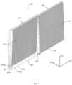
- FIGs. 1 to 3 illustrate diagrams of a multi-coil microchannel heat exchanger 100 according to a first embodiment of the present disclosure, where FIG. 1 illustrates a perspective view of the multi-coil microchannel heat exchanger 100; FIG. 2 illustrates a front view of the multi-coil microchannel heat exchanger 100; and FIG. 3 illustrates a left side view of the multi-coil microchannel heat exchanger 100.
- a length direction D1 For the multi-coil microchannel heat exchanger 100, a length direction D1, a height direction D2 perpendicular to the length direction D1, and a thickness direction D3 perpendicular to the length direction D1 and the height direction D2 are defined to describe the relative positional relationship of each component in the multi-coil microchannel heat exchanger 100 below.
- the multi-coil microchannel heat exchanger 100 includes a first coil 110 located at a near side and a second coil 120 located at a far side.
- the near side refers to a side where maintenance or servicing procedures can be easily performed on the multi-coil microchannel heat exchanger 100.
- the near side may correspond to the left side of the paper, and the far side may correspond to the right side of the paper.
- the first coil 110 includes a first inlet header 150, a first outlet header 160, and a plurality of first microchannel tubes 110A.
- the first inlet header 150 and the first outlet header 160 each have a length L1, and the first inlet header 150 and the first outlet header 160 both extend along the length direction D1 of the multi-coil microchannel heat exchanger 100.
- the plurality of first microchannel tubes 110A are sequentially arranged along the length direction of the first coil 110 (i.e., the length direction D1 of the multi-coil microchannel heat exchanger 100).
- Each of the first microchannel tubes 110A may be a flat multiport tube extending in the height direction of the first coil 110 (i.e., the height direction D2 of the multi-coil microchannel heat exchanger 100 in this embodiment).
- two adjacent first microchannel tubes 110A generally further have fins (not shown) brazed therebetween.
- Each of the first microchannel tubes 110A includes an inlet and an outlet, the inlets of the plurality of first microchannel tubes 110A are in fluid communication with the first inlet header 150, and the outlets of the plurality of first microchannel tubes 110A are in fluid communication with the first outlet header 160.
- the first coil 110 further includes a first bracket 140A.
- the first bracket 140A may be a flat slab made of aluminum or an aluminum alloy extending from the top to the bottom of the first coil 110 in the height direction D2 of the first coil 110.
- the first bracket 140A is fixed to the last first microchannel tube 110A of the first coil 110 (i.e., the first microchannel tube 110A located at the rightmost end of the first coil 110 in the length direction D1 of the first coil 110).
- the first coil 110 further includes a first end support 130A.
- the first end support 130A may be a flat slab extending from the top to the bottom of the first coil 110 in the height direction D2 of the first coil 110.
- the first end support 130A is fixed to the first first microchannel tube 110A of the first coil 110 (i.e., the first microchannel tube 110A located at the leftmost end of the first coil 110 in the length direction D1 of the first coil 110).
- the second coil 120 includes a second inlet header 170, a second outlet header 180, and a plurality of second microchannel tubes 120A.
- the second inlet header 170 and the second outlet header 180 each have a length L2, and both the second inlet header 170 and the second outlet header 180 extend along the length direction D1 of the multi-coil microchannel heat exchanger 100.
- the plurality of second microchannel tubes 120A are sequentially arranged along the length direction D1 of the second coil 120 (i.e., the length direction D1 of the multi-coil microchannel heat exchanger 100).
- Each of the second microchannel tubes 120A may be a flat multiport tube extending in the height direction D2 of the second coil 120.
- two adjacent second microchannel tubes 120A generally further have fins (not shown) brazed therebetween.
- Each second microchannel tube 120A includes an inlet and an outlet, the second inlet header 170 is in fluid communication with the inlets of the plurality of second microchannel tubes 120A, and the second outlet header 180 is in fluid communication with the outlets of the plurality of second microchannel tubes 120A.
- the second coil 120 further includes a second bracket 140B.
- the second bracket 140B may be a flat slab made of aluminum or an aluminum alloy extending from the top to the bottom of the second coil 120 in the height direction D2 of the second coil 120.
- the second bracket 140B is fixed to the first second microchannel tube 120A of the second coil 120 (i.e., the second microchannel tube 120A located at the leftmost end of the second coil 120 in the length direction D1 of the second coil 120).
- the second coil 120 further includes a second end support 130B.
- the second end support 130B may be a flat slab extending from the top to the bottom of the second coil 120 in the height direction of the second coil 120 (in this embodiment, that is, the height direction D2 of the multi-coil microchannel heat exchanger 100).
- the second end support 130B is fixed to the last second microchannel tube 120A of the second coil 120 (i.e., the second microchannel tube 120A located at the rightmost end of the second coil 120 in the length direction D1 of the second coil 120
- the first coil 110 and the second coil 120 are essentially sequentially arranged along the length direction D1 of the multi-coil microchannel heat exchanger 100. By the fitting installation between the first bracket 140A of the first coil 110 and the second bracket 140B of the second coil 120, the first coil 110 and the second coil 120 can be connected together.
- the multi-coil microchannel heat exchanger 100 further includes a first inlet connector 199A, a first outlet connector 199B, a second inlet connector 199C and a second outlet connector 199D.
- the first inlet connector 199A is fluidly connected to the first inlet header 150 and the first outlet connector 199B is fluidly connected to the first outlet header 160.
- the second inlet connector 199C is fluidly connected to the second inlet header 170 and the second outlet connector 199D is fluidly connected to the second outlet header 180.
- the multi-coil microchannel heat exchanger 100 further includes a first inlet conduit 191, a first outlet conduit 192, a second inlet conduit 193 and a second outlet conduit 194.
- the first inlet conduit 191 is connected to the first inlet header 150 through the first inlet connector 199A
- the first outlet conduit 192 is connected to the first outlet header 160 through the first outlet connector 199B.
- the second inlet conduit 193 is connected to the second inlet header 170 through the second inlet connector 199C
- the second outlet conduit 194 is connected to the second outlet header 180 through the second outlet connector 199D.
- the multi-coil microchannel heat exchanger 100 has a first side and a second side along the length direction D1.
- the first inlet connector 199A, the first outlet connector 199B, the second inlet connector 199C, and the second outlet connector 199D are all located at the first side of the multi-coil microchannel heat exchanger 100 (i.e., the left side of the paper shown in FIG. 1 ).
- the inlets and the outlets are at the same side, such that the total length of the inlet and outlet pipes used by the multi-coil microchannel heat exchanger 100 can be relatively reduced.
- the first windward surface S11 of the first coil 110 and the second windward surface S12 of the second coil 120 are respectively located on different planes.
- the first windward surface S11 of the first coil 110 and the second windward surface S12 of the second coil 120 are parallel to each other, and the first windward surface S11 and the second windward surface S12 are parallel to the height direction D2 of the multi-coil microchannel heat exchanger 100.
- the multi-coil microchannel heat exchanger 100 shown in FIGs. 1-3 is a two-pass heat exchanger.
- the first inlet header 150, the first inlet connector 199A, the second inlet header 170, the second inlet connector 199C, the first outlet header 160, the first outlet connector 199B, the second outlet header 180 and the second outlet connector 199D are all located at the bottom of the multi-coil microchannel heat exchanger 100.
- the first inlet header 150 and the first outlet header 160 are located at the bottom of the first coil 110, and the second inlet header 170 and the second outlet header 180 are located at the bottom of the second coil 120. Since the first windward surface S11 of the first coil 110 and the second windward surface S12 of the second coil 120 are located on different planes and are parallel to each other, the first coil 110 and the second coil 120 may be sequentially arranged along the thickness direction D3 of the microchannel heat exchangers 100.
- the second inlet connector 199C and the first inlet header 150 can be arranged along the thickness direction D3 of the multi-coil microchannel heat exchanger 100, and the second outlet connector 199D and the first outlet header 160 may be arranged along the thickness direction D3 of the multi-coil microchannel heat exchanger 100.
- the second inlet connector 199C and the second outlet connector 199D located at a far side can extend through a side of the first coil 110 located at a near side in the thickness direction D3 of the multi-coil microchannel heat exchanger 100, without extending through the bottom of the first coil 110 located at the near side.
- the height of the first coil 110 located in the near side does not need to be reduced, and the second inlet connector 199C and the second outlet connector 199D located at the far side do not occupy the windward area of the first coil 110 located at the near side.
- the first inlet header 150 and the first outlet header 160 of the first coil 110, and the second inlet connector 199C and the second outlet connector 199D may be respectively arranged along the thickness direction D3 of the multi-coil microchannel heat exchanger 100.
- the first coil 110 and the second coil 120 may be the same.
- the refrigerant first flows from the first inlet conduit 191 and the second inlet conduit 193 of the multi-coil microchannel heat exchanger 100, and through the first inlet connector 199A and the second inlet connector 199C, respectively flows into the first inlet header 150 and the second inlet header 170, and then the refrigerant respectively enters the first microchannel tubes 110A of the first coil 110 and the second microchannel tubes 120A of the second coil 120.
- the refrigerant flows from the bottom of the multi-coil microchannel heat exchanger, respectively through the first microchannel tubes 110A of the first coil 110 and the second microchannel tubes 120A of the second coil 120, and to the top of the multi-coil microchannel heat exchanger, and then, flows from the top of the multi-coil microchannel heat exchanger down to the bottom of the multi-coil microchannel heat exchanger in the height direction D2.
- the refrigerant flows within the first microchannel tubes 110A and the second microchannel tubes 120A, the refrigerant respectively exchanges heat with fluid (e.g., air) outside the first microchannel tubes 110A and the second microchannel tubes 120A.
- the refrigerant After heat exchange with the external fluid, the refrigerant respectively leaves the first microchannel tubes 110A and the second microchannel tubes 120A, and then respectively flows into the first outlet header 160 and the second outlet header 180, and finally, flows, through the first outlet connector 199B and the second outlet connector 199D, into the first outlet conduit 192 and the second outlet conduit 194.
- the process of heat exchange is completed.
- the multi-coil microchannel heat exchanger 100 above is described by arranging the inlet and outlet pipes at the bottom as an example.
- the multi-coil microchannel heat exchanger 100 can also be provided with the inlet and outlet pipes at the top, which does not change the essence of the present disclosure, and these equivalent or minor changes are intended to fall within the scope of protection of the appended claims of the present disclosure.
- the multi-coil microchannel heat exchanger 100 of the first embodiment on the basis of shortening the length of the inlet and outlet pipes located at the far side, can make full use of the cross-sectional area of the air conditioning unit and increase the windward areas of the coils.
- the multi-coil microchannel heat exchanger 100 is not limited to a two-pass heat exchanger.
- the multi-coil microchannel heat exchanger 100 of the first embodiment of the present disclosure may also be a single pass heat exchanger.
- FIG. 4 illustrates a schematic structural diagram of a single pass heat exchanger, and only the headers and microchannel tubes of the first coil 110 and the second coil 120 are shown in FIG. 4 . As shown in FIG. 4 , arrows indicate the flow direction of the refrigerant. It will be understood that the single pass heat exchanger shown in FIG. 4 may have the same/similar components as the two-pass heat exchanger shown in FIGs. 1-3 . The difference from the two-pass heat exchanger shown in FIGs. 1 to 3 is that for the single pass heat exchanger shown in FIG.
- the first inlet header 150, the first inlet connector, and the second inlet header 170 and the second inlet connector is located at the bottom of the multi-coil microchannel heat exchanger 100, while the first outlet header 160, the first outlet connector, the second outlet header 180 and the second outlet connector are located at the top of the multi-coil microchannel heat exchanger 100, and vice versa.
- the first inlet header 150 is located at the bottom of the first coil 110, the second inlet header 170 is located at the bottom of the second coil 120; the first outlet header 160 is located at the top of the first coil 110, and the second outlet header 180 is located on the top of the second coil 120.
- the second inlet connector located at the far side and the first inlet header 150 of the first coil 110 located at the near side can be arranged at the bottom of the multi-coil microchannel heat exchanger 100 and along the thickness direction D3 of the multi-coil microchannel heat exchanger 100; and the second outlet connector located at the far side and the first outlet header 160 of the first coil 110 located at the near side can be arranged at the top of the multi-coil microchannel heat exchanger 100 and along the thickness direction D3 of the multi-coil microchannel heat exchanger 100.
- the second inlet connector and the second outlet connector located at the far side do not need to occupy the windward area of the first coil 110 located at the near side, and in this way, the first coil 110 located at the near side may have the same large windward area as the second coil 120 located at the far side.
- the multi-coil microchannel heat exchanger 100 includes two coils.
- the multi-coil microchannel heat exchanger 100 of the present disclosure is not limited to including two coils.
- FIG. 5 illustrates a schematic structural diagram of a two-pass heat exchanger including three coils
- FIG. 6 illustrates a structural schematic diagram of a single-pass heat exchanger including three coils
- the multi-coil microchannel heat exchanger 100 of the present disclosure may further include a third coil 930 in addition to the first coil 110 and the second coil 120.
- the first coil 110 includes a first inlet header 150, a first outlet header 160, and a plurality of first microchannel tubes 110A, where the first inlet header 150 is in fluid communication with the inlets of the plurality of the first microchannel tubes 110A, the first outlet header 160 is in fluid communication with the outlets of the plurality of the first microchannel tubes 110A.
- the second coil 120 includes a second inlet header 170, a second outlet header 180, and a plurality of second microchannel tubes 120A, where the second inlet header 170 is in fluid communication with the inlets of the plurality of the second microchannel tubes 120A, the second outlet header 180 is in fluid communication with the outlets of the plurality of the second microchannel tubes 120A.
- the third coil 930 includes a third inlet header 940, a third outlet header 950, and a plurality of third microchannel tubes 930A, where the third inlet header 940 is in fluid communication with the inlets of the plurality of the third microchannel tubes 930A, and the third outlet header 950 is in fluid communication with the outlets of the plurality of the third microchannel tubes 930A.
- the first coil 110, the second coil 120, and the third coil 930 may have the same structure. Therefore, the structure and manufacturing process of the multi-coil microchannel heat exchanger 100 can be simplified, and the cost can be reduced.
- the multi-coil microchannel heat exchanger 100 of the present disclosure further includes a first inlet connector 199A and a first outlet connector, a second inlet connector 199C and a second outlet connector, and a third inlet connector 199E and a third outlet connector (not shown).
- the first inlet connector 199A is fluidly connected to the first inlet header 150 and the first outlet connector is fluidly connected to the first outlet header 160.
- the second inlet connector 199C is fluidly connected to the second inlet header 170 and the second outlet connector is fluidly connected to the second outlet header 180.
- the third inlet connector 199E is fluidly connected to the third inlet header 940 and the third outlet connector is fluidly connected to the third outlet header 950.
- the first coil 110, the second coil 120, and the third coil 930 may be sequentially arranged along the length direction D1 of the multi-coil microchannel heat exchanger 100, and the first coil 110, the second coil 120 and the third coil 930 are also successively arranged along the thickness direction D3 of the multi-coil microchannel heat exchanger 100, such that the first windward surface S11 of the first coil 110, the second windward surface S12 of the second coil 120, and the third windward surface S93 of the third coil 930 are all located on different planes, so as to facilitate the arrangement of the inlet and outlet pipes of the far side coils, without occupying the windward areas of the near side coils. Therefore, the first coil 110, the second coil 120, and the third coil 930 may have the same windward area.
- the first inlet header 150, the first outlet header 160, the first inlet connector 199A, the first outlet connector, the second inlet header 170, the second outlet header 180, the second inlet connector 199C, the second outlet connector, the third inlet header 940, the third outlet header 950, the third inlet connector 199E and the third outlet connector are all located at the bottom (or top) of the multi-coil microchannel heat exchanger 100.
- the first inlet header 150, the first outlet header 160, the second inlet connector 199C, the second outlet connector, the third inlet connector 199E and the third outlet connector are arranged along the thickness direction D3 of the multi-coil microchannel heat exchanger 100.
- the first inlet header 150, the first inlet connector 199A, the second inlet header 170, the second inlet connector 199C, the third inlet header 940, the third inlet connector 199E are all located at the bottom (or top) of the multi-coil microchannel heat exchanger 100; while the first outlet header 160, the first outlet connector, the second outlet header 180, the second outlet connector, the third outlet header 950 and the third outlet connector are all located at the top (or bottom) of the multi-coil microchannel heat exchanger 100.
- the first inlet header 150, the second inlet connector 199C and the third inlet connector 199E are arranged at the bottom (or top) of the multi-coil microchannel heat exchanger 100 and along the thickness direction D3 of the multi-coil microchannel heat exchanger 100; and the first outlet header 160, the second outlet connector and the third outlet connector are arranged at the top (or bottom) of the multi-coil microchannel heat exchanger 100 and along the thickness direction D3 of the multi-coil microchannel heat exchanger 100.
- the multi-coil microchannel heat exchanger 100 of the present disclosure is not limited to include two or three coils. In other embodiments, the multi-coil microchannel heat exchanger 100 of the present disclosure may further include more coils.
- FIGs. 7 and 8 illustrate schematic diagrams of a multi-coil microchannel heat exchanger 200 according to a second embodiment of the present disclosure, where FIG. 7 illustrates a front view of the multi-coil microchannel heat exchanger 200; FIG. 8 illustrates a left side view of the multi-coil microchannel heat exchanger 200.
- the difference from the multi-coil microchannel heat exchanger 100 of the first embodiment shown in FIGs. 1 to 3 is that in the multi-coil microchannel heat exchanger 100 of the second embodiment shown in FIGs. 7 and 8 , viewed along the length direction D1 of the multi-coil microchannel heat exchanger 200, the first windward surface S21 of the first coil 210 and the second windward surface S22 of the second coil 220 are parallel to each other and inclined to the height direction D2 of the multi-coil microchannel heat exchanger 200. Therefore, when the cross-sectional area of the air conditioning unit is constant, the height of the coils can be higher, and the heat exchange area can be larger.
- the multi-coil microchannel heat exchanger 200 of the second embodiment can have a larger heat exchange area than the multi-coil microchannel heat exchanger 100 of the first embodiment.
- FIGs. 7 and 8 show that the multi-coil microchannel heat exchanger 200 according to the second embodiment of the present disclosure may be a two-pass heat exchanger.
- the first inlet header 250, the first inlet connector 299A, the second inlet header 270, the second inlet connector 299C, the first outlet header 260, the first outlet connector 299B, the second outlet header 280 and the second outlet connector 299D are all located at the bottom (or top) of the multi-coil microchannel heat exchanger 200.
- first inlet header 250 and the first outlet header 260 are located at the bottom (or top) of the first coil 210
- the second inlet header 270 and the second outlet header 280 are located at the bottom (or top) of the second coil 220.
- the first inlet header 250 and the first outlet header 260 of the first coil 210, and the second inlet connector 299C and the second outlet connector 299D may be arranged at the bottom (or top) of the multi-coil microchannel heat exchanger 200 and along the thickness direction D3 of the multi-coil microchannel heat exchanger 200.
- the first inlet header 250, the first inlet connector 299A, the second inlet header 270 and the second inlet connector 299C are located at the bottom (or top) of the multi-coil microchannel heat exchanger 200, while the first outlet header 260, the first outlet connector 299B, the second outlet header 280, and the second outlet connector 299D are located at the top (or bottom) of the multi-coil microchannel heat exchanger 200.
- first inlet header 250 is located at the bottom (or top) of the first coil 210
- second inlet header 270 is located at the bottom (or top) of the second coil 220
- first outlet header 260 is located at the top (or bottom) of the first coil 210
- second outlet header 280 is located at the top (or bottom) of the second coil 220.
- the second inlet connector 299C located at the far side and the first inlet header 250 of the first coil 210 located at the near side may be arranged at the bottom (or top) of the multi-coil microchannel heat exchanger 200 and along the thickness direction D3 of the multi-coil microchannel heat exchanger 200; the second outlet connector 299D located at the far side and the first outlet header 260 of the first coil 210 located at the near side can be arranged at the top (or bottom) of the multi-coil microchannel heat exchanger 200 and along the thickness direction D3 of the multi-coil microchannel heat exchanger 200.
- the multi-coil microchannel heat exchanger 200 of the second embodiment can further increase the windward area of the coil on the basis of shortening the length of the inlet and outlet pipes at the far side.
- FIGs. 9 and 10 illustrate schematic diagrams of a multi-coil microchannel heat exchanger 300 according to a third embodiment of the present disclosure, where FIG. 9 illustrates a perspective view of the multi-coil microchannel heat exchanger 300; FIG. 10 illustrates a left side view of the multi-coil microchannel heat exchanger 300.
- the difference from the multi-coil microchannel heat exchanger 100 of the first embodiment shown in FIGs. 1 to 3 is that in the multi-coil microchannel heat exchanger 300 of the third embodiment shown in FIGs. 9 and 10 , viewed along the length direction D1 of the multi-coil microchannel heat exchanger 300, the first windward surface S31 of the first coil 310 and the second windward surface S32 of the second coil 320 are cross each other, and the first windward surface S31 and the second windward surface S32 are generally arranged in an inverted V shape.
- the first coil 310 includes a first upper end and a first lower end along the height direction D2 of the multi-coil microchannel heat exchanger 300
- the second coil 320 includes a second upper end and a second lower end along the height direction D2 of the multi-coil microchannel heat exchanger 300.
- the first upper end of the first coil 310 and the second upper end of the second coil 320 are aligned in the thickness direction D3 of the multi-coil microchannel heat exchanger 300
- the first lower end of the first coil 310 and the second lower end of the second coil 320 are offset (not overlapped) in the thickness direction D3 of the multi-coil microchannel heat exchanger 300.
- the multi-coil microchannel heat exchanger 300 of the third embodiment of the present application adopts a two-pass heat exchanger shown in FIG. 9 and FIG. 10 .
- the first inlet header 350, the first inlet connector 399A, the second inlet header 370, the second inlet connector 399C, the first outlet header 360, the first outlet connector 399B, the second outlet header 380 and the second outlet connector 399D are all located at the bottom of the multi-coil microchannel heat exchanger 300.
- the first inlet header 350 and the first outlet header 360 are located at the bottom of the first coil 310, and the second inlet header 370 and the second outlet header 380 are located at the bottom of the second coil 320.
- the second inlet connector 399C and the second outlet connector 399D located at the far side may be arranged on one side of the first coil 310 located at the near side along the thickness direction D3 of the multi-coil microchannel heat exchanger 300. Accordingly, the first inlet header 350 and the first outlet header 360 of the first coil 310, and the second inlet connector 399C and the second outlet connector 399D may be respectively arranged along the thickness direction D3 of the multi-coil microchannel heat exchanger 300.
- first upper end of the first coil 310 and the second upper end of the second coil 320 may also be offset in the thickness direction D3 of the multi-coil microchannel heat exchanger 300, and the first lower end of the first coil 310 and the second lower end of the second coil 320 are aligned in the thickness direction D3 of the multi-coil microchannel heat exchanger 300.
- the inlet and outlet pipes of the multi-coil microchannel heat exchanger 300 are arranged at the side with offset arrangement.
- the multi-coil microchannel heat exchanger 300 of the third embodiment can further increase the windward area of the coil on the basis of shortening the length of the far side inlet and outlet pipes.
- FIGs. 11 and 12 illustrate diagrams of a multi-coil microchannel heat exchanger 400 according to a fourth embodiment of the present disclosure, where FIG. 11 illustrates a perspective view of the multi-coil microchannel heat exchanger 400; FIG. 9 illustrates a left side view of the multi-coil microchannel heat exchanger 400.
- the difference from the multi-coil microchannel heat exchanger 300 of the third embodiment shown in FIGs. 9 and 10 is that in the multi-coil microchannel heat exchanger 400 of the fourth embodiment shown in FIGs. 11 and 12 , viewed along the length direction D1 of the multi-coil microchannel heat exchanger 400, the first windward surface S41 of the first coil 410 and the second windward surfaces S42 of the second coil 420 cross each other, and the first windward surface S41 and the second windward surface S42 are generally arranged in an X shape.
- the first coil 410 includes a first upper end and a first lower end along the height direction D2 of the multi-coil microchannel heat exchanger 400
- the second coil 420 includes a second upper end and a second lower end along the height direction D2 of the multi-coil microchannel heat exchanger 400.
- the first upper end of the first coil 410 and the second upper end of the second coil 420 are offset (not overlapped) in the thickness direction D3 of the multi-coil microchannel heat exchanger 400
- the first lower end of the first coil 410 and the second lower end of the second coil 420 are also offset (not overlapped) in the thickness direction D3 of the multi-coil microchannel heat exchanger 400.
- FIGs. 11 and 12 show that the multi-coil microchannel heat exchanger 400 according to the fourth embodiment of the present disclosure may be a two-pass heat exchanger.
- the first inlet header 450, the first inlet connector 499A, the second inlet header 470, the second inlet connector 499C, the first outlet header 460, the first outlet connector 499B, the second outlet header 480 and the second outlet connector 499D are all located at the bottom (or top) of the multi-coil microchannel heat exchanger 400.
- the first inlet header 450 and the first outlet header 460 are located at the bottom (or top) of the first coil 410, and the second inlet header 470 and the second outlet header 480 are located at the bottom (or top) of the second coil 420.
- the first inlet header 450 and first outlet header 460 of the first coil 410, and the second inlet connector 499C and second outlet connector 499D may be arranged at the bottom (or top) of the multi-coil microchannel heat exchanger 400 and along the thickness direction D3 of the multi-coil microchannel heat exchanger 400.
- the first inlet header 450, the first inlet connector 499A, the second inlet header 470 and the second inlet Connector 499C are located at the bottom (or top) of multi-coil microchannel heat exchanger 400, while the first outlet header 460, the first outlet connector 499B, the second outlet header 480 and the second outlet connector 499D are located at the top (or bottom) of the multi-coil microchannel heat exchanger 400.
- first inlet header 450 is located at the bottom (or top) of the first coil 410
- second inlet header 470 is located at the bottom (or top) of the second coil 420
- the second inlet connector 499C located at the far side is located at one side of the first inlet header 450 along the thickness direction D3 of the multi-coil microchannel heat exchanger 400
- the second inlet connector 499C located at the far side and the first inlet header 450 of the first coil 410 located at the near side are arranged at the bottom (or top) of the multi-coil microchannel heat exchanger 400 and along the thickness direction D3 of the multi-coil microchannel heat exchanger 400
- the first outlet header 460 is located at the top (or bottom) of the first coil 410
- the second outlet header 480 is located at the top (or bottom) of the second coil 420
- the second outlet connector 499D is located at another side of the first outlet header 460 along the thickness direction D3 of the multi-coil microchannel heat exchanger 400
- the multi-coil microchannel heat exchanger 400 of the fourth embodiment can further increase the windward area of the coils on the basis of shortening the length of the far side inlet and outlet pipes.
- FIGs. 13 and 14 illustrate diagrams of a multi-coil microchannel heat exchanger 500 according to a fifth embodiment of the present disclosure, where FIG. 13 illustrates a perspective view of the multi-coil microchannel heat exchanger 500; FIG. 14 illustrates a left side view of the multi-coil microchannel heat exchanger 500.
- the multi-coil microchannel heat exchanger 500 includes at least one layer of coils, each layer of coils includes at least two coils, and the at least two coils are successively arranged along the length direction D1 of the multi-coil microchannel heat exchanger 500, and the at least two coils include the first coil 110 and the second coil 120.
- the multi-coil microchannel heat exchanger 500 includes two layers of coils, a first layer of coils 501 and a second layer of coils 502. Each layer of coils has a substantially similar structure to the multi-coil microchannel heat exchanger 100 of the first embodiment shown in FIGs. 1 to 3 .
- the coils of the same layer in the first layer of coils 501 and the second layer of coils 502 are arranged offset from each other in the thickness direction D3 of the multi-coil microchannel heat exchanger 500.
- the difference from the multi-coil microchannel heat exchanger 100 of the first embodiment shown in FIGs. 1 to 3 is that in the multi-coil microchannel heat exchanger 500 of the fifth embodiment shown in FIGs.
- the first layer of coils 501 and the second layer of coils 502 are arranged offset from each other in the height direction D2 of the multi-coil microchannel heat exchanger 500. That is, the first layer of coils 501 and the second layer of coils 502 are located at different heights, and the first layer of coils 501 and the second layer of coils 502 partially overlap in the height direction D2 of the multi-coil microchannel heat exchanger 500.
- the cross-sectional area of the entire air conditioning unit can be fully utilized, and the first layer of coils 501 located at the outer layer has little effect on the windward area of the second layer of coils 502 located in the inner layer. Therefore, the second layer of coils 502 located at the inner side can also have a large windward area, thereby the entire windward area of the multi-coil microchannel heat exchanger 500 can be increased as much as possible.
- the first layer of coils 501 and the second layer of coils 502 may be the same. Therefore, the multi-coil microchannel heat exchanger 500 of the fifth embodiment of the present disclosure can be formed by using same coils, thereby greatly simplifying the structure, simplifying the manufacturing and production processes, and reducing costs.
- the multi-coil microchannel heat exchanger 500 may further include a deflector 503, and the deflector 503 is connected to the upper end of the first layer of coils 501 and the lower end of the second layer of coils 502.
- the deflector 503 is inclined, such that a larger V-shape wind collector can be formed on the windward side of the second layer of coils 502 located at the inner side, so as to increase the flow of external fluid, and further, increase the windward area of the second layer of coils 502 located at the inner side.
- the multi-coil microchannel heat exchanger 500 of the fifth embodiment on the basis of shortening the length of the far side inlet and outlet pipes, can make full use of the cross-sectional area of the air conditioning unit, can further increase the windward area of the coils, can meet larger heat exchange requirements and is suitable for larger tonnage air conditioning units.
- FIGs. 15 and 16 illustrate diagrams of a multi-coil microchannel heat exchanger 600 according to a sixth embodiment of the present disclosure, where FIG. 15 illustrates a front view of the multi-coil microchannel heat exchanger 600; FIG. 16 illustrates a left side view of the multi-coil microchannel heat exchanger 600.
- the multi-coil microchannel heat exchanger 600 includes two layers of coils, a first layer of coils 601 and a second layer of coils 602. Each layer of coils has a substantially similar structure to the multi-coil microchannel heat exchanger 200 of the second embodiment shown in FIGs. 7 and 8 .
- the difference from the multi-coil microchannel heat exchanger 200 of the second embodiment shown in FIGs. 7 and 8 is that, in the multi-coil microchannel heat exchanger 600 of the sixth embodiment shown in FIGs. 15 and 16 , the first layer of coils 601 and the second layer of coils 602 are arranged offset from each other in the height direction D2 of the multi-coil microchannel heat exchanger 600.
- the entire cross-sectional area of the air conditioning unit can be fully utilized, the outer first layer of coils 601 has little effect on the windward area of the inner second layer of coils 602, so the inner second layer of coils 602 can also maintain a larger windward area.
- the entire windward area of the multi-coil microchannel heat exchanger 600 can be increased as much as possible.
- the first layer of coils 601 and the second layer of coils 602 may be same. Therefore, the multi-coil microchannel heat exchanger 600 of the sixth embodiment of the present disclosure can be formed by using same coils, thereby greatly simplifying the structure, simplifying the manufacturing and production processes, and reducing costs.
- the multi-coil microchannel heat exchanger 600 may further include a deflector 603, and the deflector 603 connects the upper end of the first layer of coils 601 and the lower end of the second layer of coils 602.
- the deflector 603 is inclined, such that a larger V-shape wind collector can be formed on the windward side of the inner second layer of coils 602, so as to increase the flow of the external fluid, and further, increase the windward area of the inner second layer of coils 602.
- the multi-coil microchannel heat exchanger 600 of the sixth embodiment on the basis of shortening the length of the far side inlet and outlet pipes, can make full use of the cross-sectional area of the air conditioning unit, can further increase the windward area of the coils, can meet larger heat exchange requirements and is suitable for larger tonnage air conditioning units.
- FIGs. 17 and 18 illustrate diagrams of a multi-coil microchannel heat exchanger 700 according to a seventh embodiment of the present disclosure, where FIG. 17 illustrates a perspective view of the multi-coil microchannel heat exchanger 700; FIG. 18 illustrates a left side view of the multi-coil microchannel heat exchanger 700.
- the multi-coil microchannel heat exchanger 700 includes two layers of coils, a first layer of coils 701 and a second layer of coils 702.
- Each layer of coils has a generally similar structure to the multi-coil microchannel heat exchanger 300 of the third embodiment shown in FIGs. 9 and 10 .
- the difference from the multi-coil microchannel heat exchanger 300 of the third embodiment shown in FIGs. 9 and 10 is that in the multi-coil microchannel heat exchanger 700 of the seventh embodiment shown in FIGs. 17 and 18 , the first layer of coils 701 and the second layer of coils 702 are arranged offset from each other in the height direction D2 of the multi-coil microchannel heat exchanger 700.
- the entire cross-sectional area of the air conditioning unit can be fully utilized, the outer first layer of coils 701 has little effect on the windward area of the inner second layer of coils 702, so the inner second layer of coils 702 can also maintain a larger windward area.
- the entire windward area of the multi-coil microchannel heat exchanger 700 can be increased as much as possible.
- the first layer of coils 701 and the second layer of coils 702 may be same. Therefore, the multi-coil microchannel heat exchanger 700 of the seventh embodiment of the present disclosure can be formed by using same coils, thereby greatly simplifying the structure, simplifying the manufacturing and production processes, and reducing costs.
- the multi-coil microchannel heat exchanger 700 may further include a deflector 703, and the deflector 703 connects the upper end of the first layer of coils 701 and the lower end of the second layer of coils 702.
- the deflector 703 is inclined, such that a larger V-shape wind collector can be formed on the windward side of the inner second layer of coils 702, so as to increase the flow of the external fluid, and further, increase the windward area of the inner second layer of coils 702.
- the multi-coil microchannel heat exchanger 700 of the seventh embodiment on the basis of shortening the length of the far side inlet and outlet pipes, can make full use of the cross-sectional area of the air conditioning unit, can further increase the windward area of the coils, can meet larger heat exchange requirements and is suitable for larger tonnage air conditioning units.
- FIGs. 19 and 20 illustrate diagrams of a multi-coil microchannel heat exchanger 800 according to an eighth embodiment of the present disclosure, where FIG. 19 illustrates a perspective view of the multi-coil microchannel heat exchanger 800; FIG. 17 illustrates a left side view of the multi-coil microchannel heat exchanger 800.
- the multi-coil microchannel heat exchanger 800 includes two layers of coils, a first layer of coils 801 and a second layer of coils 802. Each layer of coils has a generally similar structure to the multi-coil microchannel heat exchanger 400 of the fourth embodiment shown in FIGs. 11 and 12 .
- the difference from the multi-coil microchannel heat exchanger 400 of the fourth embodiment shown in FIGs. 11 and 12 is that in the multi-coil microchannel heat exchanger 800 of the eighth embodiment shown in FIGs. 19 and 20 , the first layer of coils 801 and the second layer of coils 802 are arranged offset from each other in the height direction D2 of the multi-coil microchannel heat exchanger 800.
- the entire cross-sectional area of the air conditioning unit can be fully utilized, the outer first layer of coils 801 has little effect on the windward area of the inner second layer of coils 802, so the inner second layer of coils 802 can also maintain a larger windward area.
- the entire windward area of the multi-coil microchannel heat exchanger 800 can be increased as much as possible.
- the first layer of coils 801 and the second layer of coils 802 may be same. Therefore, the multi-coil microchannel heat exchanger 800 of the eighth embodiment of the present disclosure can be formed by using same coils, thereby greatly simplifying the structure, simplifying the manufacturing and production processes, and reducing costs.
- the multi-coil microchannel heat exchanger 800 may further include a deflector, and the deflector connects the upper end of the first layer of coils 801 and the lower end of the second layer of coils 802.
- the deflector is inclined, such that a larger V-shape wind collector can be formed on the windward side of the inner second layer of coils 802, so as to increase the flow of the external fluid, and further, increase the windward area of the inner second layer of coils 802.
- the multi-coil microchannel heat exchanger 800 of the eighth embodiment on the basis of shortening the length of the far side inlet and outlet pipes, can make full use of the cross-sectional area of the air conditioning unit, can further increase the windward area of the coils, can meet larger heat exchange requirements and is suitable for larger tonnage air conditioning units.
- the multi-coil microchannel heat exchanger of the present disclosure may include one or more layers of coils arranged along the height direction D2 of the multi-coil microchannel heat exchanger.
- Each layer of coils may include essentially two or more coils sequentially arranged along the length direction D1 of the multi-coil microchannel heat exchanger.
- the windward surfaces of all coils in the same layer are located on different planes, such that the far side inlet/outlet connectors do not need to pass through the bottom of the near side coils, but can extend from one side of the near side coil in the thickness direction D3 of the multi-coil microchannel heat exchanger, and the far side inlet/outlet connectors and near side coil inlet/outlet headers can be arranged along the thickness direction D3 of the multi-coil microchannel heat exchanger. Therefore, without reducing the height of the near side coils, the windward areas of the near side coils can be increased.
- the different layers of coils are arranged offset from each other in the height direction D2 of the multi-coil microchannel heat exchanger. That is, the different layers of coils are respectively located at different heights, and adjacent layers of coils partially overlap in the height direction D2 of the multi-coil microchannel heat exchanger.
- the present disclosure further provides an air conditioning unit.
- the air conditioning unit may include at least one of the multi-coil microchannel heat exchangers 100-800 described in the above embodiments.
- the multi-coil microchannel heat exchangers 100-800 and the air conditioning unit with at least one of the multi-coil microchannel heat exchangers 100-800 described in the various embodiments of the present disclosure, on the basis of shortening the length of the far side inlet and outlet pipes, can increase the windward area of the coils.
Landscapes
- Engineering & Computer Science (AREA)
- Mechanical Engineering (AREA)
- General Engineering & Computer Science (AREA)
- Physics & Mathematics (AREA)
- Thermal Sciences (AREA)
- Chemical & Material Sciences (AREA)
- Combustion & Propulsion (AREA)
- Heat-Exchange Devices With Radiators And Conduit Assemblies (AREA)
- Air Filters, Heat-Exchange Apparatuses, And Housings Of Air-Conditioning Units (AREA)
Applications Claiming Priority (2)
| Application Number | Priority Date | Filing Date | Title |
|---|---|---|---|
| CN202211168210.2A CN115751701B (zh) | 2022-09-23 | 2022-09-23 | 多盘管微通道热交换器及空调机组 |
| PCT/CN2022/121566 WO2022247971A2 (zh) | 2022-09-23 | 2022-09-27 | 多盘管微通道热交换器及空调机组 |
Publications (4)
| Publication Number | Publication Date |
|---|---|
| EP4273464A2 true EP4273464A2 (de) | 2023-11-08 |
| EP4273464A4 EP4273464A4 (de) | 2024-09-04 |
| EP4273464B1 EP4273464B1 (de) | 2025-07-23 |
| EP4273464B8 EP4273464B8 (de) | 2025-08-27 |
Family
ID=84230318
Family Applications (1)
| Application Number | Title | Priority Date | Filing Date |
|---|---|---|---|
| EP22810694.4A Active EP4273464B8 (de) | 2022-09-23 | 2022-09-27 | Mehrspuliger mikrokanalwärmetauscher und klimaanlage |
Country Status (4)
| Country | Link |
|---|---|
| US (1) | US12173972B2 (de) |
| EP (1) | EP4273464B8 (de) |
| CN (1) | CN115751701B (de) |
| WO (1) | WO2022247971A2 (de) |
Families Citing this family (2)
| Publication number | Priority date | Publication date | Assignee | Title |
|---|---|---|---|---|
| CN116678039A (zh) * | 2023-06-20 | 2023-09-01 | 特灵空调系统(中国)有限公司 | 换热器及空调 |
| CN118500150B (zh) * | 2024-05-27 | 2024-11-12 | 惠州市华盛源机电有限公司 | 一种盘管弯曲式铜管散热器 |
Family Cites Families (21)
| Publication number | Priority date | Publication date | Assignee | Title |
|---|---|---|---|---|
| WO2008064228A1 (en) * | 2006-11-22 | 2008-05-29 | Johnson Controls Technology Company | Multichannel evaporator with flow mixing microchannel tubes |
| WO2009117159A2 (en) * | 2008-03-20 | 2009-09-24 | Carrier Corporation | A micro-channel heat exchanger suitable for bending |
| US20100006276A1 (en) * | 2008-07-11 | 2010-01-14 | Johnson Controls Technology Company | Multichannel Heat Exchanger |
| WO2011005986A2 (en) * | 2009-07-10 | 2011-01-13 | Johnson Controls Technology Company | Multichannel heat exchanger with differing fin spacing |
| WO2012002698A2 (ko) * | 2010-06-30 | 2012-01-05 | 갑을오토텍(주) | 열교환기 |
| GB2537066B (en) * | 2013-06-24 | 2017-05-17 | Airedale Int Air Conditioning Ltd | Air conditioner having angled heat exchangers |
| CN104596153B (zh) * | 2013-10-31 | 2018-09-28 | 杭州三花微通道换热器有限公司 | 微通道换热器 |
| CN106918166B (zh) * | 2015-12-24 | 2023-03-03 | 丹佛斯微通道换热器(嘉兴)有限公司 | 换热器和空调系统 |
| CN107218822B (zh) * | 2016-03-21 | 2019-04-19 | 丹佛斯微通道换热器(嘉兴)有限公司 | 换热器和空调系统 |
| US10012967B2 (en) | 2016-06-12 | 2018-07-03 | Apple Inc. | Coordinating modifications by multiple users to a shared automated environment |
| CN205919730U (zh) * | 2016-08-25 | 2017-02-01 | 特灵空调系统(中国)有限公司 | 用于微通道换热器的进气/液分配结构及微通道换热器 |
| US10359218B2 (en) * | 2016-10-28 | 2019-07-23 | Lennox Industries Inc. | Manifold design to eliminate fractures on multistage heat exchanger coils |
| JP2018100803A (ja) * | 2016-12-21 | 2018-06-28 | 三星電子株式会社Samsung Electronics Co.,Ltd. | 熱交換装置、空気調和装置の室内機及び空気調和装置の室外機 |
| CN107702382B (zh) * | 2017-05-24 | 2020-07-07 | 杭州三花微通道换热器有限公司 | 微通道蒸发器 |
| CN207975825U (zh) * | 2018-02-08 | 2018-10-16 | 特灵空调系统(中国)有限公司 | 盘管装置及空调系统 |
| JP7004847B2 (ja) * | 2018-12-19 | 2022-01-21 | 三菱電機株式会社 | 熱交換器及び冷凍サイクル装置 |
| JP2020100255A (ja) * | 2018-12-21 | 2020-07-02 | サンデン・オートモーティブクライメイトシステム株式会社 | 凝縮器、車両用空気調和装置 |
| US20220196345A1 (en) * | 2019-07-22 | 2022-06-23 | Mitsubishi Electric Corporation | Heat exchanger, method of manufacturing the same, and air-conditioning apparatus |
| CN112747502A (zh) * | 2019-10-29 | 2021-05-04 | 浙江盾安热工科技有限公司 | 换热器 |
| US11656033B2 (en) | 2020-01-09 | 2023-05-23 | Carrier Corporation | Combined core microchannel heat exchanger |
| US11415346B2 (en) * | 2020-04-30 | 2022-08-16 | Trane International Inc. | System and method for common side connections for oversized multislab microchannel heat exchanger |
-
2022
- 2022-09-23 CN CN202211168210.2A patent/CN115751701B/zh active Active
- 2022-09-27 WO PCT/CN2022/121566 patent/WO2022247971A2/zh not_active Ceased
- 2022-09-27 US US18/013,733 patent/US12173972B2/en active Active
- 2022-09-27 EP EP22810694.4A patent/EP4273464B8/de active Active
Also Published As
| Publication number | Publication date |
|---|---|
| EP4273464B8 (de) | 2025-08-27 |
| WO2022247971A2 (zh) | 2022-12-01 |
| EP4273464A4 (de) | 2024-09-04 |
| CN115751701B (zh) | 2023-08-25 |
| US20240102748A1 (en) | 2024-03-28 |
| US12173972B2 (en) | 2024-12-24 |
| WO2022247971A3 (zh) | 2023-09-21 |
| EP4273464B1 (de) | 2025-07-23 |
| CN115751701A (zh) | 2023-03-07 |
Similar Documents
| Publication | Publication Date | Title |
|---|---|---|
| EP4273464A2 (de) | Mehrspuliger mikrokanalwärmetauscher und klimaanlage | |
| CN101936670B (zh) | 一种微通道、平行流、全铝扁管焊接式结构换热器及应用 | |
| CN104335000B (zh) | 换热器及热交换方法 | |
| CN105651081B (zh) | 双排折弯式换热器及其制造方法 | |
| CN202582275U (zh) | 多流体管壳式换热器 | |
| CN104019583B (zh) | 平行流换热器 | |
| US20110056667A1 (en) | Integrated multi-circuit microchannel heat exchanger | |
| CN103123185A (zh) | 热交换器及其制造方法 | |
| CN106767038A (zh) | 换热器及空调器 | |
| CN217383880U (zh) | 微通道换热器 | |
| CN105277040B (zh) | 换热器 | |
| CN215114092U (zh) | 换热器 | |
| CN104019582A (zh) | 平行流换热器 | |
| US20240384938A1 (en) | Heat Exchanger | |
| CN218523782U (zh) | 微通道换热器及空调器 | |
| US10126065B2 (en) | Heat exchanger assembly having a refrigerant distribution control using selective tube port closures | |
| CN216159687U (zh) | 换热组件 | |
| CN211601198U (zh) | 换热器 | |
| CN201373628Y (zh) | 组合式空调全铝换热器及其模块化组装结构 | |
| CN216159690U (zh) | 换热器 | |
| WO2023208129A1 (zh) | 微通道换热器组及具有其的空调系统 | |
| CN215216776U (zh) | 蒸发器 | |
| CN216159688U (zh) | 换热器 | |
| CN115727689A (zh) | 换热器 | |
| CN213747274U (zh) | 组合式换热器 |
Legal Events
| Date | Code | Title | Description |
|---|---|---|---|
| STAA | Information on the status of an ep patent application or granted ep patent |
Free format text: STATUS: THE INTERNATIONAL PUBLICATION HAS BEEN MADE |
|
| PUAI | Public reference made under article 153(3) epc to a published international application that has entered the european phase |
Free format text: ORIGINAL CODE: 0009012 |
|
| STAA | Information on the status of an ep patent application or granted ep patent |
Free format text: STATUS: REQUEST FOR EXAMINATION WAS MADE |
|
| 17P | Request for examination filed |
Effective date: 20230804 |
|
| AK | Designated contracting states |
Kind code of ref document: A2 Designated state(s): AL AT BE BG CH CY CZ DE DK EE ES FI FR GB GR HR HU IE IS IT LI LT LU LV MC MK MT NL NO PL PT RO RS SE SI SK SM TR |
|
| A4 | Supplementary search report drawn up and despatched |
Effective date: 20240806 |
|
| RIC1 | Information provided on ipc code assigned before grant |
Ipc: F28F 9/26 20060101ALI20240731BHEP Ipc: F28F 9/02 20060101ALI20240731BHEP Ipc: F28D 7/04 20060101ALI20240731BHEP Ipc: F24F 13/30 20060101AFI20240731BHEP |
|
| GRAP | Despatch of communication of intention to grant a patent |
Free format text: ORIGINAL CODE: EPIDOSNIGR1 |
|
| STAA | Information on the status of an ep patent application or granted ep patent |
Free format text: STATUS: GRANT OF PATENT IS INTENDED |
|
| INTG | Intention to grant announced |
Effective date: 20250325 |
|
| GRAS | Grant fee paid |
Free format text: ORIGINAL CODE: EPIDOSNIGR3 |
|
| GRAA | (expected) grant |
Free format text: ORIGINAL CODE: 0009210 |
|
| STAA | Information on the status of an ep patent application or granted ep patent |
Free format text: STATUS: THE PATENT HAS BEEN GRANTED |
|
| GRAT | Correction requested after decision to grant or after decision to maintain patent in amended form |
Free format text: ORIGINAL CODE: EPIDOSNCDEC |
|
| AK | Designated contracting states |
Kind code of ref document: B1 Designated state(s): AL AT BE BG CH CY CZ DE DK EE ES FI FR GB GR HR HU IE IS IT LI LT LU LV MC MK MT NL NO PL PT RO RS SE SI SK SM TR |
|
| DAV | Request for validation of the european patent (deleted) | ||
| DAX | Request for extension of the european patent (deleted) | ||
| RAP3 | Party data changed (applicant data changed or rights of an application transferred) |
Owner name: TRANE AIR CONDITIONING SYSTEMS (CHINA) CO., LTD. |
|
| REG | Reference to a national code |
Ref country code: GB Ref legal event code: FG4D |
|
| REG | Reference to a national code |
Ref country code: CH Ref legal event code: EP Ref country code: CH Ref legal event code: PK Free format text: BERICHTIGUNG B8 |
|
| P01 | Opt-out of the competence of the unified patent court (upc) registered |
Free format text: CASE NUMBER: APP_31334/2025 Effective date: 20250630 |
|
| RAP4 | Party data changed (patent owner data changed or rights of a patent transferred) |
Owner name: TRANE AIR CONDITIONING SYSTEMS (CHINA) CO., LTD. |
|
| REG | Reference to a national code |
Ref country code: IE Ref legal event code: FG4D |
|
| REG | Reference to a national code |
Ref country code: DE Ref legal event code: R096 Ref document number: 602022018188 Country of ref document: DE |
|
| P02 | Opt-out of the competence of the unified patent court (upc) changed |
Free format text: CASE NUMBER: UPC_APP_3468_4273464/2025 Effective date: 20250815 |
|
| PGFP | Annual fee paid to national office [announced via postgrant information from national office to epo] |
Ref country code: DE Payment date: 20250924 Year of fee payment: 4 |
|
| PGFP | Annual fee paid to national office [announced via postgrant information from national office to epo] |
Ref country code: AT Payment date: 20251020 Year of fee payment: 4 Ref country code: FR Payment date: 20250901 Year of fee payment: 4 |
|
| REG | Reference to a national code |
Ref country code: NL Ref legal event code: MP Effective date: 20250723 |
|
| PG25 | Lapsed in a contracting state [announced via postgrant information from national office to epo] |
Ref country code: PT Free format text: LAPSE BECAUSE OF FAILURE TO SUBMIT A TRANSLATION OF THE DESCRIPTION OR TO PAY THE FEE WITHIN THE PRESCRIBED TIME-LIMIT Effective date: 20251124 |
|
| PG25 | Lapsed in a contracting state [announced via postgrant information from national office to epo] |
Ref country code: NL Free format text: LAPSE BECAUSE OF FAILURE TO SUBMIT A TRANSLATION OF THE DESCRIPTION OR TO PAY THE FEE WITHIN THE PRESCRIBED TIME-LIMIT Effective date: 20250723 |
|
| REG | Reference to a national code |
Ref country code: AT Ref legal event code: MK05 Ref document number: 1816782 Country of ref document: AT Kind code of ref document: T Effective date: 20250723 |
|
| PG25 | Lapsed in a contracting state [announced via postgrant information from national office to epo] |
Ref country code: IS Free format text: LAPSE BECAUSE OF FAILURE TO SUBMIT A TRANSLATION OF THE DESCRIPTION OR TO PAY THE FEE WITHIN THE PRESCRIBED TIME-LIMIT Effective date: 20251123 |
|
| PG25 | Lapsed in a contracting state [announced via postgrant information from national office to epo] |
Ref country code: NO Free format text: LAPSE BECAUSE OF FAILURE TO SUBMIT A TRANSLATION OF THE DESCRIPTION OR TO PAY THE FEE WITHIN THE PRESCRIBED TIME-LIMIT Effective date: 20251023 |
|
| REG | Reference to a national code |
Ref country code: LT Ref legal event code: MG9D |
|
| PG25 | Lapsed in a contracting state [announced via postgrant information from national office to epo] |
Ref country code: AT Free format text: LAPSE BECAUSE OF FAILURE TO SUBMIT A TRANSLATION OF THE DESCRIPTION OR TO PAY THE FEE WITHIN THE PRESCRIBED TIME-LIMIT Effective date: 20250723 |
|
| PG25 | Lapsed in a contracting state [announced via postgrant information from national office to epo] |
Ref country code: FI Free format text: LAPSE BECAUSE OF FAILURE TO SUBMIT A TRANSLATION OF THE DESCRIPTION OR TO PAY THE FEE WITHIN THE PRESCRIBED TIME-LIMIT Effective date: 20250723 |
|
| PG25 | Lapsed in a contracting state [announced via postgrant information from national office to epo] |
Ref country code: HR Free format text: LAPSE BECAUSE OF FAILURE TO SUBMIT A TRANSLATION OF THE DESCRIPTION OR TO PAY THE FEE WITHIN THE PRESCRIBED TIME-LIMIT Effective date: 20250723 |
|
| PG25 | Lapsed in a contracting state [announced via postgrant information from national office to epo] |
Ref country code: GR Free format text: LAPSE BECAUSE OF FAILURE TO SUBMIT A TRANSLATION OF THE DESCRIPTION OR TO PAY THE FEE WITHIN THE PRESCRIBED TIME-LIMIT Effective date: 20251024 |
|
| PG25 | Lapsed in a contracting state [announced via postgrant information from national office to epo] |
Ref country code: SE Free format text: LAPSE BECAUSE OF FAILURE TO SUBMIT A TRANSLATION OF THE DESCRIPTION OR TO PAY THE FEE WITHIN THE PRESCRIBED TIME-LIMIT Effective date: 20250723 |
|
| PG25 | Lapsed in a contracting state [announced via postgrant information from national office to epo] |
Ref country code: LV Free format text: LAPSE BECAUSE OF FAILURE TO SUBMIT A TRANSLATION OF THE DESCRIPTION OR TO PAY THE FEE WITHIN THE PRESCRIBED TIME-LIMIT Effective date: 20250723 |
|
| PG25 | Lapsed in a contracting state [announced via postgrant information from national office to epo] |
Ref country code: BG Free format text: LAPSE BECAUSE OF FAILURE TO SUBMIT A TRANSLATION OF THE DESCRIPTION OR TO PAY THE FEE WITHIN THE PRESCRIBED TIME-LIMIT Effective date: 20250723 Ref country code: PL Free format text: LAPSE BECAUSE OF FAILURE TO SUBMIT A TRANSLATION OF THE DESCRIPTION OR TO PAY THE FEE WITHIN THE PRESCRIBED TIME-LIMIT Effective date: 20250723 |
|
| PG25 | Lapsed in a contracting state [announced via postgrant information from national office to epo] |
Ref country code: RS Free format text: LAPSE BECAUSE OF FAILURE TO SUBMIT A TRANSLATION OF THE DESCRIPTION OR TO PAY THE FEE WITHIN THE PRESCRIBED TIME-LIMIT Effective date: 20251023 |
|
| PG25 | Lapsed in a contracting state [announced via postgrant information from national office to epo] |
Ref country code: ES Free format text: LAPSE BECAUSE OF FAILURE TO SUBMIT A TRANSLATION OF THE DESCRIPTION OR TO PAY THE FEE WITHIN THE PRESCRIBED TIME-LIMIT Effective date: 20250723 |