EP4267370B1 - Nachgusskühlvorrichtung für vorformlinge oder behälter aus thermoplastischem kunststoff - Google Patents
Nachgusskühlvorrichtung für vorformlinge oder behälter aus thermoplastischem kunststoff Download PDFInfo
- Publication number
- EP4267370B1 EP4267370B1 EP21845095.5A EP21845095A EP4267370B1 EP 4267370 B1 EP4267370 B1 EP 4267370B1 EP 21845095 A EP21845095 A EP 21845095A EP 4267370 B1 EP4267370 B1 EP 4267370B1
- Authority
- EP
- European Patent Office
- Prior art keywords
- cooling
- picking
- preform
- tube
- releasing
- Prior art date
- Legal status (The legal status is an assumption and is not a legal conclusion. Google has not performed a legal analysis and makes no representation as to the accuracy of the status listed.)
- Active
Links
Images


Classifications
-
- B—PERFORMING OPERATIONS; TRANSPORTING
- B29—WORKING OF PLASTICS; WORKING OF SUBSTANCES IN A PLASTIC STATE IN GENERAL
- B29C—SHAPING OR JOINING OF PLASTICS; SHAPING OF MATERIAL IN A PLASTIC STATE, NOT OTHERWISE PROVIDED FOR; AFTER-TREATMENT OF THE SHAPED PRODUCTS, e.g. REPAIRING
- B29C49/00—Blow-moulding, i.e. blowing a preform or parison to a desired shape within a mould; Apparatus therefor
- B29C49/42—Component parts, details or accessories; Auxiliary operations
- B29C49/64—Heating or cooling preforms, parisons or blown articles
- B29C49/6409—Thermal conditioning of preforms
- B29C49/6427—Cooling of preforms
-
- B—PERFORMING OPERATIONS; TRANSPORTING
- B29—WORKING OF PLASTICS; WORKING OF SUBSTANCES IN A PLASTIC STATE IN GENERAL
- B29C—SHAPING OR JOINING OF PLASTICS; SHAPING OF MATERIAL IN A PLASTIC STATE, NOT OTHERWISE PROVIDED FOR; AFTER-TREATMENT OF THE SHAPED PRODUCTS, e.g. REPAIRING
- B29C49/00—Blow-moulding, i.e. blowing a preform or parison to a desired shape within a mould; Apparatus therefor
- B29C49/02—Combined blow-moulding and manufacture of the preform or the parison
- B29C49/06—Injection blow-moulding
-
- B—PERFORMING OPERATIONS; TRANSPORTING
- B29—WORKING OF PLASTICS; WORKING OF SUBSTANCES IN A PLASTIC STATE IN GENERAL
- B29C—SHAPING OR JOINING OF PLASTICS; SHAPING OF MATERIAL IN A PLASTIC STATE, NOT OTHERWISE PROVIDED FOR; AFTER-TREATMENT OF THE SHAPED PRODUCTS, e.g. REPAIRING
- B29C2949/00—Indexing scheme relating to blow-moulding
- B29C2949/07—Preforms or parisons characterised by their configuration
- B29C2949/0715—Preforms or parisons characterised by their configuration the preform having one end closed
-
- B—PERFORMING OPERATIONS; TRANSPORTING
- B29—WORKING OF PLASTICS; WORKING OF SUBSTANCES IN A PLASTIC STATE IN GENERAL
- B29C—SHAPING OR JOINING OF PLASTICS; SHAPING OF MATERIAL IN A PLASTIC STATE, NOT OTHERWISE PROVIDED FOR; AFTER-TREATMENT OF THE SHAPED PRODUCTS, e.g. REPAIRING
- B29C49/00—Blow-moulding, i.e. blowing a preform or parison to a desired shape within a mould; Apparatus therefor
- B29C49/42—Component parts, details or accessories; Auxiliary operations
- B29C49/4205—Handling means, e.g. transfer, loading or discharging means
-
- B—PERFORMING OPERATIONS; TRANSPORTING
- B29—WORKING OF PLASTICS; WORKING OF SUBSTANCES IN A PLASTIC STATE IN GENERAL
- B29K—INDEXING SCHEME ASSOCIATED WITH SUBCLASSES B29B, B29C OR B29D, RELATING TO MOULDING MATERIALS OR TO MATERIALS FOR MOULDS, REINFORCEMENTS, FILLERS OR PREFORMED PARTS, e.g. INSERTS
- B29K2067/00—Use of polyesters or derivatives thereof, as moulding material
- B29K2067/003—PET, i.e. poylethylene terephthalate
-
- B—PERFORMING OPERATIONS; TRANSPORTING
- B29—WORKING OF PLASTICS; WORKING OF SUBSTANCES IN A PLASTIC STATE IN GENERAL
- B29L—INDEXING SCHEME ASSOCIATED WITH SUBCLASS B29C, RELATING TO PARTICULAR ARTICLES
- B29L2031/00—Other particular articles
- B29L2031/712—Containers; Packaging elements or accessories, Packages
- B29L2031/7158—Bottles
Definitions
- the present invention relates to a production plant for producing preforms or containers made of thermoplastic material, for example made of PET, and in particular to a cooling apparatus employed in said plants.
- a cooling apparatus corresponding to the preamble of claim 1 is disclosed in WO2013/140326A1 .
- thermoplastic containers in particular of bottles, is a process which starting from the raw material, which generally is polyethylene terephthalate or PET, allows obtaining finished containers having a shape - even a particularly complex shape - adapted to the most varied needs of the market and particularly lightweight and also resistant when subjected to strong pressures at room temperature.
- the raw material which generally is polyethylene terephthalate or PET
- the passage from PET in the raw state in the form of granules to plastic container can be achieved by choosing a single-stage process or a two-stage process.
- the single-stage process is performed with a single production plant in which the passage from PET granules to preform by means of a mold injection step, and the passage from preform to plastic container by means of the stretch-blowing step, occurs continuously, without letting the preform completely cool to room temperature.
- the preform still maintains part of the latent heat remaining from the injection step, with significant energy saving, because the preforms require less heat to then be brought back to the temperature suitable for blowing with respect to the case in which they are to be reheated starting from room temperature.
- a so-called "two-stage” process is performed in two generally, but not necessarily, separate plants: one production plant performs the first part of the production process of the containers with the passage from PET granules to preform, that is, it performs the injection step of the PET preforms into injection molds.
- the second part of the process which transforms the preform into the final container in a blowing machine with the stretch-blowing technique, which is the one generally used today to blow PET containers, is performed in the other production plant.
- the two-stage process may also be performed in the same production plant, which provides injecting preforms and blowing the same into containers, but the two operations are performed at two separate times.
- the preforms are first cooled in special cooling plants up to reaching room temperature, to then be stored while waiting to be introduced into appropriate ovens to bring them back to the temperature required to perform the blowing process typical of the thermoplastic used or required for the stretch-blowing, in the event PET is used.
- So-called stars comprising a rotatable wheel provided with a series of grippers having extendible arms equipped with jaws may be employed for transporting the preforms or final containers in plants consisting of rotary carousels.
- thermoplastic preforms or containers in particular PET
- One of these problems in particular relates to the cooling times of the preforms or containers, such as for example test tubes.
- the solution is a rotary cooling apparatus which can be employed in production plants of preforms or containers, such as test tubes, with a high production speed, that is, a rotary cooling apparatus of preforms or containers made of thermoplastic material, in particular made of PET, which comprises:
- Another aspect of the invention provides a production plant for producing preforms or containers made of thermoplastic material comprising the aforesaid rotary cooling apparatus, wherein said rotary cooling apparatus is arranged downstream of a rotary injection molding machine, and wherein a transfer wheel is provided between said rotary injection molding machine and said rotary cooling apparatus.
- a further aspect of the invention relates to an operating method of the rotary cooling apparatus, wherein a transfer wheel is provided upstream of the rotary cooling apparatus, the method at full speed comprising, for each cooling device, the following steps during the rotation of the carousel:
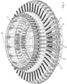
- FIG. 1 it is shown a production plant for producing preforms or containers, such as for example, test tubes, made of thermoplastic material, the plant comprising a rotary cooling apparatus 10 according to the invention.
- the rotary cooling apparatus 10 is arranged downstream of a rotary injection molding machine 11, for example but not necessarily, a rotary injection-compression molding machine.
- a transfer wheel 12 is provided between the rotary injection molding machine 11 and the rotary cooling apparatus 10. Any technical solution for unloading the cooled preforms or containers may be provided downstream of the rotary cooling apparatus 10. For example, one or more unloading wheels 13 may be provided, as shown in Figure 1 .
- the curvilinear arrows in Figure 1 indicate rotation orientation of the various components of the production plant.
- a linear type of unloading device or any other suitable unloading device for example one or more containers for receiving the cooled products, can be provided as an alternative to the unloading wheels 13.
- an optical control system of the individual preforms or of the individual containers downstream of the rotary cooling apparatus 10 is provided.
- the three unloading wheels 13 downstream of the rotary cooling apparatus 10 are used to prepare such an optical control system of the individual preforms or of the individual containers.
- a quality check of the individual preforms or of the individual containers can be performed in line, thus avoiding to discard a whole set of molded preforms or containers in the event of defects of an individual product, as occurs in the solutions of the background art.
- the rotary cooling apparatus of the invention comprises:
- the guide element 6 may be a continuous or non-continuous annular element, that is an annular element which is closed or open in a portion thereof, concentric to carousel 1, and provided with areas at different heights.
- the at least one picking and releasing device 5 is adapted to translate upwards or downwards transversely to the radial direction, for example perpendicularly to the radial direction, by means of the cooperation thereof with the fixed guide element 6 during the rotation of carousel 1.
- each picking and releasing device 5 comprises a support structure 14 which can slide along a substantially vertical guide 15 fastened to the structure of the carousel.
- a support structure 14 is provided, preferably at the upper end thereof, with a roller or lifter element 16 which, during the rotation of carousel 1, by sliding or following the guide element 6, causes the upwards or downwards translation of the corresponding picking and releasing device 5.
- the support structure 14 instead is provided with grippers 18, preferably at the lower end thereof.
- at least one cooling device 3 and at least one corresponding picking and releasing device 5 are arranged, and therefore define, a cooling module 2 of the rotary cooling apparatus.
- At least one guide 15 is fastened on each cooling module.
- each cooling module 2 comprises three cooling devices 3 and three corresponding picking and releasing devices 5.
- cooling devices 3 and respective picking and releasing devices 5 may be provided for each cooling module 2.
- a single cooling device 3 and a single corresponding picking and releasing device 5 may also be provided.
- At least one movement device 17 is provided, for example at least one motor with related transmission, adapted to impart, to a corresponding cooling device 3, the translation motion along the radial direction Y, in a first orientation or in a second orientation opposite to the first orientation, preferably but not necessarily equal to the pitch between one cooling tube and the one adjacent thereto.
- the plurality of cooling tubes 4 of each cooling device 3, which substantially are adjacent one with respect to the successive one along the radial direction, is arranged on a base 7 which slides on a guide 9 in turn integrally fastened to the cooling module 2.
- the movement device 17 for example at least one motor with related transmission, imparts the translation motion along the direction Y which is radial to base 7.
- the cooling tubes 4 each define a substantially vertical axis thereof, which is perpendicular to the longitudinal axis defined by base 7.
- Each cooling tube 4 is, for example, provided with an internal circuit for a cooling fluid, for example water, and with an air suction duct to facilitate the introduction of the preform into the cooling tube when released by the picking and releasing device 5.
- a cooling fluid for example water
- each cooling device 3 is provided with channels for the cooling fluid which are connected to the internal circuit of each cooling tube, and is provided with a channel for the air connected to the suction duct of each cooling tube 4.
- at least one inlet channel and at least one outlet channel for the cooling fluid are provided in the base 7.
- a linear type of unloading device or any other suitable unloading device for example one or more containers for receiving the cooled products, may be provided as an alternative to the unloading wheel 13.
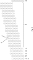
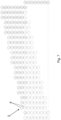
- cooling tubes 4 in Figures 6 and 7 containing a respective preform therein are indicated by a lined background, while the empty cooling tubes are indicated with no background.
- the operating method at full speed of the rotary cooling apparatus 10 comprises, for each cooling device 3, during the rotation of carousel 1, the following steps ( Figure 6 ):
- Receiving position means the position of the cooling tube below the corresponding picking and releasing device 5, in particular the position of the cooling tube 4 when the latter is coaxial to the area enclosed by the grippers 18, in closed position, of the picking and releasing device 5.
- the picking from the transfer wheel 12 and the releasing into the cooling tubes 4, for example from the first to the nth tube, of the respective preforms to be cooled, are provided in a starting step of the apparatus of the invention, which precedes the operation at full speed.
- An example of this starting step is shown in Figure 7 .
- picking the preforms, or the containers, from the transfer wheel 12 occurs at a first height; releasing the preforms into the respective cooling tubes 4 occurs at a second height, lower than the first height; picking the preforms from the respective cooling tube 4 occurs at a third height, lower than or equal to the second height; and releasing the preforms to the unloading wheel 13, or other suitable unloading device, occurs at a fourth height, higher than the second height.
- the first height and the fourth height may be equal to each other.
- each preform is gripped by the transfer wheel 12 by means of a respective picking and releasing device 5 at point A.
- the preform is released into the corresponding tube 4 of the respective cooling device 3 (step b), and after some revolutions of the rotary apparatus 10 in which the cooling of the aforesaid preform is completed and steps c) to g) are performed, the preform is grasped again by the same picking and releasing device 5 which removes it from the tube and releases it downstream of the rotary cooling apparatus 10 at point B (step h).
- the picking and releasing devices 5 are always free of preforms in stretch AB of the rotary apparatus 10 defining an acute central angle ⁇ . At full speed operation, each cooling device 3 in this stretch AB has only one empty cooling tube.
Landscapes
- Engineering & Computer Science (AREA)
- Manufacturing & Machinery (AREA)
- Mechanical Engineering (AREA)
- Physics & Mathematics (AREA)
- Thermal Sciences (AREA)
- Blow-Moulding Or Thermoforming Of Plastics Or The Like (AREA)
- Processing And Handling Of Plastics And Other Materials For Molding In General (AREA)
Claims (10)
- Rotationskühlvorrichtung zum Kühlen von Vorformlingen oder Behältern aus thermoplastischem Material, umfassend:- einen Umlaufförderer (1), der einen Umfang aufweist und dazu ausgelegt ist, sich um eine im Wesentlichen vertikale Drehachse X zu drehen;- mindestens ein festes Führungselement (6), das entlang mindestens eines Teils des Umfangs angeordnet ist;- eine Vielzahl von Kühleinrichtungen (3), die entlang des Umfangs des Umlaufförderers angeordnet sind, wobei jede Kühleinrichtung (3) dazu ausgelegt ist, sich im Wesentlichen horizontal entlang einer radialen Richtung in Bezug auf die Drehachse X zu bewegen, und mit einer Vielzahl von Kühlrohren (4) versehen ist, die dazu ausgelegt sind, jeweils einen entsprechenden zu kühlenden Vorformling aufzunehmen;
dadurch gekennzeichnet, dass die Kühlrohre (4) der Vielzahl von Kühlrohren (4) der Reihe nach entlang der radialen Richtung angeordnet sind;
und dadurch, dass die Rotationskühlvorrichtung ferner umfasst- eine Vielzahl von Aufnahme- und Freigabeeinrichtungen (5), wobei jede Aufnahme- und Freigabeeinrichtung (5) mit einer entsprechenden Kühleinrichtung (3) zusammenwirkt und dazu ausgelegt ist, einen Vorformling von einem Transferrad aufzunehmen, den Vorformling abwechselnd in eines der Kühlrohre (4) freizugeben und den Vorformling wieder aufzunehmen, um ihn stromabwärts der Rotationskühlvorrichtung freizugeben, wobei die mindestens eine Aufnahme- und Freigabeeinrichtung (5) dazu ausgelegt ist, sich durch Zusammenwirken mit dem mindestens einen festen Führungselement (6) während einer Drehung des Umlaufförderers (1) quer zu der radialen Richtung nach oben oder nach unten zu bewegen. - Vorrichtung nach Anspruch 1, wobei mindestens eine Kühleinrichtung (3) und mindestens eine entsprechende Aufnahme- und Freigabeeinrichtung (5) ein Kühlmodul (2) der Rotationskühlvorrichtung definieren.
- Vorrichtung nach Anspruch 2, wobei jedes Kühlmodul (2) eine, zwei, drei oder mehr Kühleinrichtungen (3) und eine, zwei, drei oder mehr entsprechende Aufnahme- und Freigabeeinrichtungen (5) umfasst.
- Vorrichtung nach einem der vorhergehenden Ansprüche, wobei eine Bewegungseinrichtung (17) vorgesehen ist, die dazu ausgelegt ist, die mindestens eine Kühleinrichtung (3) in eine Translationsbewegung entlang der radialen Richtung in eine erste Ausrichtung oder in eine zweite, der ersten Ausrichtung entgegengesetzte Ausrichtung zu versetzen, die vorzugsweise gleich dem Abstand zwischen einem Kühlrohr und dem dazu benachbarten ist.
- Vorrichtung nach einem der vorhergehenden Ansprüche, wobei die mindestens eine Aufnahme- und Freigabeeinrichtung (5) dazu ausgelegt ist, sich senkrecht zu der radialen Richtung zu bewegen.
- Vorrichtung nach einem der vorhergehenden Ansprüche, wobei die Vielzahl von Kühlrohren (4) auf einer gleitenden Grundplatte (7) angeordnet ist, die dazu ausgelegt ist, auf mindestens einer Führung (9), die an einer Struktur des Umlaufförderers befestigt ist, zu gleiten.
- Vorrichtung nach Anspruch 6, wobei jedes Kühlrohr (4) mit einem internen Kreislauf für ein Kühlfluid und mit einem Luftansaugkanal versehen ist, um das Einführen des Vorformlings in das Kühlrohr zu erleichtern, und wobei die Grundplatte (7) mit Kanälen für das Kühlfluid versehen ist, die mit dem internen Kreislauf jedes Kühlrohrs verbunden sind, und mit einem Kanal für die Luft versehen ist, der mit dem Ansaugkanal jedes Kühlrohrs verbunden ist.
- Anlage zur Fertigung von Vorformlingen oder Behältern aus thermoplastischem Material, die eine Rotationskühlvorrichtung (10) nach einem der vorhergehenden Ansprüche umfasst, wobei die Rotationskühlvorrichtung (10) stromabwärts einer Rotationsspritzgießmaschine (11) angeordnet ist und wobei ein Transferrad (12) zwischen der Rotationsspritzgießmaschine (11) und der Rotationskühlvorrichtung (10) vorgesehen ist.
- Betriebsverfahren für eine Rotationskühlvorrichtung nach einem der vorhergehenden Ansprüche, wobei ein Transferrad (12) stromaufwärts der Rotationskühlvorrichtung (10) vorgesehen ist, wobei das Verfahren bei voller Geschwindigkeit für jede Kühleinrichtung (3) die folgenden Schritte während der Drehung des Umlaufförderers (1) umfasst:a) Bereitstellen von zu kühlenden Vorformlingen oder Behältern, die in jeweilige Kühlrohre (4) eingeführt werden, mit Ausnahme eines ersten Rohrs, das in einer Aufnahmeposition für einen ersten Vorformling vorgesehen ist;b) Aufnehmen eines ersten Vorformlings aus dem Transferrad (12) mittels einer Aufnahme- und Freigabeeinrichtung (5) und Freigeben des ersten Vorformlings in das erste Rohr;c) Bewegen der Kühleinrichtung (3) entlang der radialen Richtung in eine erste Ausrichtung oder in eine zweite, der ersten Ausrichtung entgegengesetzte Ausrichtung, so dass ein zweites Rohr, vorzugsweise benachbart zu dem ersten Rohr, die Aufnahmeposition erreicht;d) Aufnehmen eines zweiten Vorformlings aus dem zweiten Rohr mittels der Aufnahme- und Freigabeeinrichtung (5) und Freigeben desselben stromabwärts der Rotationskühlvorrichtung;e) Aufnehmen eines neuen, zweiten Vorformlings aus dem Transferrad mittels der Aufnahme- und Freigabeeinrichtung (5) und Freigeben des neuen, zweiten Vorformlings in das zweite Rohr;f) Wiederholen der Schritte c) bis e) für ein drittes Rohr und bis zu einem n-ten Rohr der Vielzahl von Kühlrohren, die jeweils zum Kühlen eines dritten Vorformlings bis zu einem n-ten Vorformling ausgelegt sind;g) Bewegen der Kühleinrichtung (3) entlang der radialen Richtung in die zweite Ausrichtung oder erste Ausrichtung, so dass das erste Rohr in die Aufnahmeposition zurückkehrt;h) Aufnehmen des ersten Vorformlings aus dem ersten Rohr mittels der Aufnahme- und Freigabeeinrichtung (5) und Freigeben desselben stromabwärts der Rotationskühlvorrichtung;i) Wiederholen der Schritte b) bis h).
- Verfahren nach Anspruch 9, wobei das Aufnehmen der Vorformlinge aus dem ersten Transferrad in einer ersten Höhe erfolgt; das Freigeben der Vorformlinge in die jeweiligen Kühlrohre in einer zweiten Höhe erfolgt, die niedriger als die erste Höhe ist; das Aufnehmen der Vorformlinge aus dem jeweiligen Kühlrohr in einer dritten Höhe erfolgt, die niedriger als oder gleich der zweiten Höhe ist; und das Freigeben der Vorformlinge stromabwärts der Rotationskühlvorrichtung in einer vierten Höhe erfolgt, die höher als die zweite Höhe ist.
Applications Claiming Priority (2)
| Application Number | Priority Date | Filing Date | Title |
|---|---|---|---|
| IT102020000032357A IT202000032357A1 (it) | 2020-12-24 | 2020-12-24 | Apparato di raffreddamento post-stampaggio per preforme o contenitori in termoplastica |
| PCT/IB2021/062060 WO2022137097A1 (en) | 2020-12-24 | 2021-12-21 | Post moulding cooling apparatus for preforms or containers made of thermoplastic |
Publications (2)
| Publication Number | Publication Date |
|---|---|
| EP4267370A1 EP4267370A1 (de) | 2023-11-01 |
| EP4267370B1 true EP4267370B1 (de) | 2024-11-20 |
Family
ID=74875172
Family Applications (1)
| Application Number | Title | Priority Date | Filing Date |
|---|---|---|---|
| EP21845095.5A Active EP4267370B1 (de) | 2020-12-24 | 2021-12-21 | Nachgusskühlvorrichtung für vorformlinge oder behälter aus thermoplastischem kunststoff |
Country Status (7)
| Country | Link |
|---|---|
| US (1) | US20240042670A1 (de) |
| EP (1) | EP4267370B1 (de) |
| JP (1) | JP2024503253A (de) |
| CA (1) | CA3203088A1 (de) |
| IT (1) | IT202000032357A1 (de) |
| PL (1) | PL4267370T3 (de) |
| WO (1) | WO2022137097A1 (de) |
Family Cites Families (8)
| Publication number | Priority date | Publication date | Assignee | Title |
|---|---|---|---|---|
| JP4266434B2 (ja) * | 1999-04-12 | 2009-05-20 | 日精エー・エス・ビー機械株式会社 | プリフォームの冷却装置 |
| JP4266686B2 (ja) * | 2003-04-01 | 2009-05-20 | 日精エー・エス・ビー機械株式会社 | ネック部結晶化装置及びネック部結晶化方法 |
| EP2546176B1 (de) * | 2008-04-18 | 2016-01-20 | SACMI Cooperativa Meccanici Imola Società Cooperativa | Formpressblasverfahren und -vorrichtung |
| ITVR20120048A1 (it) * | 2012-03-19 | 2013-09-20 | Sacmi Imola Sc | Impianto per la produzione di preforme in plastica |
| ITRM20130487A1 (it) * | 2013-09-03 | 2015-03-04 | Sipa Progettazione Automaz | Apparato di raffreddamento post-stampaggio per preforme in termoplastica |
| CN104552899B (zh) * | 2014-12-31 | 2017-01-04 | 广州达意隆包装机械股份有限公司 | 提高结晶机瓶口冷却生产效率的装置及方法 |
| EP3348377B1 (de) * | 2017-01-12 | 2019-10-09 | Sidel Participations | Behälterförder- und -kühlvorrichtung, verfahren zum betrieb solch einer behälterförder- und -kühlvorrichtung und behälterbehandlungsmaschine mit solch einer behälterförder- und -kühlvorrichtung |
| IT202100006479A1 (it) * | 2021-03-18 | 2022-09-18 | Sipa Progettazione Automaz | Dispositivo di raffreddamento per una pluralità di preforme o contenitori tubolari |
-
2020
- 2020-12-24 IT IT102020000032357A patent/IT202000032357A1/it unknown
-
2021
- 2021-12-21 US US18/258,438 patent/US20240042670A1/en active Pending
- 2021-12-21 PL PL21845095.5T patent/PL4267370T3/pl unknown
- 2021-12-21 EP EP21845095.5A patent/EP4267370B1/de active Active
- 2021-12-21 CA CA3203088A patent/CA3203088A1/en active Pending
- 2021-12-21 JP JP2023537674A patent/JP2024503253A/ja active Pending
- 2021-12-21 WO PCT/IB2021/062060 patent/WO2022137097A1/en not_active Ceased
Also Published As
| Publication number | Publication date |
|---|---|
| PL4267370T3 (pl) | 2025-04-22 |
| JP2024503253A (ja) | 2024-01-25 |
| CA3203088A1 (en) | 2022-06-30 |
| EP4267370A1 (de) | 2023-11-01 |
| US20240042670A1 (en) | 2024-02-08 |
| WO2022137097A1 (en) | 2022-06-30 |
| IT202000032357A1 (it) | 2022-06-24 |
Similar Documents
| Publication | Publication Date | Title |
|---|---|---|
| EP0534367B1 (de) | Maschine zum Konditionieren von Kunststofformteilen | |
| CN100475483C (zh) | 塑料物品的注射装置和方法 | |
| US5643620A (en) | Continuous injection molding system | |
| US10023399B2 (en) | Grippers for thermoplastic containers | |
| US4036925A (en) | Continuous stretch blow molding method | |
| CN1043515C (zh) | 注射拉伸吹制成形的方法和装置 | |
| US6217819B1 (en) | Universal single-row and multi-row insert stretch blow molding method and apparatus therefor | |
| US6713013B2 (en) | Single-row and multi-row stretch blow molding method and apparatus therefor | |
| EP4267370B1 (de) | Nachgusskühlvorrichtung für vorformlinge oder behälter aus thermoplastischem kunststoff | |
| CN215242794U (zh) | 用于借助预成型件分选装置处理塑料预成型件的设备 | |
| EP3041658B1 (de) | Nachformungs-kühlvorrichtung für aus einem thermoplastischen material hergestellte vorformlinge | |
| US11660801B2 (en) | Starwheel preform orienting apparatus | |
| JP6798745B1 (ja) | 樹脂容器の製造方法 | |
| EP3254825B1 (de) | Maschine zum formen und blasformen von behältern aus kunststoff vorformlingen. | |
| EP2809493B1 (de) | Förder- und kühlvorrichtung für vorformen | |
| US20020142065A1 (en) | Device for treating preforms to obtain containers made of plastics | |
| US12441046B2 (en) | Method and system for producing plastic containers | |
| WO2026002909A1 (en) | Improved moulding of plastic containers |
Legal Events
| Date | Code | Title | Description |
|---|---|---|---|
| STAA | Information on the status of an ep patent application or granted ep patent |
Free format text: STATUS: UNKNOWN |
|
| STAA | Information on the status of an ep patent application or granted ep patent |
Free format text: STATUS: THE INTERNATIONAL PUBLICATION HAS BEEN MADE |
|
| PUAI | Public reference made under article 153(3) epc to a published international application that has entered the european phase |
Free format text: ORIGINAL CODE: 0009012 |
|
| STAA | Information on the status of an ep patent application or granted ep patent |
Free format text: STATUS: REQUEST FOR EXAMINATION WAS MADE |
|
| 17P | Request for examination filed |
Effective date: 20230721 |
|
| AK | Designated contracting states |
Kind code of ref document: A1 Designated state(s): AL AT BE BG CH CY CZ DE DK EE ES FI FR GB GR HR HU IE IS IT LI LT LU LV MC MK MT NL NO PL PT RO RS SE SI SK SM TR |
|
| P01 | Opt-out of the competence of the unified patent court (upc) registered |
Effective date: 20240220 |
|
| DAV | Request for validation of the european patent (deleted) | ||
| DAX | Request for extension of the european patent (deleted) | ||
| GRAP | Despatch of communication of intention to grant a patent |
Free format text: ORIGINAL CODE: EPIDOSNIGR1 |
|
| GRAP | Despatch of communication of intention to grant a patent |
Free format text: ORIGINAL CODE: EPIDOSNIGR1 |
|
| STAA | Information on the status of an ep patent application or granted ep patent |
Free format text: STATUS: GRANT OF PATENT IS INTENDED |
|
| INTG | Intention to grant announced |
Effective date: 20240614 |
|
| GRAS | Grant fee paid |
Free format text: ORIGINAL CODE: EPIDOSNIGR3 |
|
| GRAA | (expected) grant |
Free format text: ORIGINAL CODE: 0009210 |
|
| STAA | Information on the status of an ep patent application or granted ep patent |
Free format text: STATUS: THE PATENT HAS BEEN GRANTED |
|
| AK | Designated contracting states |
Kind code of ref document: B1 Designated state(s): AL AT BE BG CH CY CZ DE DK EE ES FI FR GB GR HR HU IE IS IT LI LT LU LV MC MK MT NL NO PL PT RO RS SE SI SK SM TR |
|
| REG | Reference to a national code |
Ref country code: GB Ref legal event code: FG4D |
|
| REG | Reference to a national code |
Ref country code: CH Ref legal event code: EP |
|
| REG | Reference to a national code |
Ref country code: DE Ref legal event code: R096 Ref document number: 602021022225 Country of ref document: DE |
|
| REG | Reference to a national code |
Ref country code: IE Ref legal event code: FG4D |
|
| REG | Reference to a national code |
Ref country code: LT Ref legal event code: MG9D |
|
| REG | Reference to a national code |
Ref country code: NL Ref legal event code: MP Effective date: 20241120 |
|
| PG25 | Lapsed in a contracting state [announced via postgrant information from national office to epo] |
Ref country code: HR Free format text: LAPSE BECAUSE OF FAILURE TO SUBMIT A TRANSLATION OF THE DESCRIPTION OR TO PAY THE FEE WITHIN THE PRESCRIBED TIME-LIMIT Effective date: 20241120 Ref country code: IS Free format text: LAPSE BECAUSE OF FAILURE TO SUBMIT A TRANSLATION OF THE DESCRIPTION OR TO PAY THE FEE WITHIN THE PRESCRIBED TIME-LIMIT Effective date: 20250320 Ref country code: PT Free format text: LAPSE BECAUSE OF FAILURE TO SUBMIT A TRANSLATION OF THE DESCRIPTION OR TO PAY THE FEE WITHIN THE PRESCRIBED TIME-LIMIT Effective date: 20250320 |
|
| PG25 | Lapsed in a contracting state [announced via postgrant information from national office to epo] |
Ref country code: FI Free format text: LAPSE BECAUSE OF FAILURE TO SUBMIT A TRANSLATION OF THE DESCRIPTION OR TO PAY THE FEE WITHIN THE PRESCRIBED TIME-LIMIT Effective date: 20241120 Ref country code: NL Free format text: LAPSE BECAUSE OF FAILURE TO SUBMIT A TRANSLATION OF THE DESCRIPTION OR TO PAY THE FEE WITHIN THE PRESCRIBED TIME-LIMIT Effective date: 20241120 |
|
| PG25 | Lapsed in a contracting state [announced via postgrant information from national office to epo] |
Ref country code: BG Free format text: LAPSE BECAUSE OF FAILURE TO SUBMIT A TRANSLATION OF THE DESCRIPTION OR TO PAY THE FEE WITHIN THE PRESCRIBED TIME-LIMIT Effective date: 20241120 |
|
| PG25 | Lapsed in a contracting state [announced via postgrant information from national office to epo] |
Ref country code: ES Free format text: LAPSE BECAUSE OF FAILURE TO SUBMIT A TRANSLATION OF THE DESCRIPTION OR TO PAY THE FEE WITHIN THE PRESCRIBED TIME-LIMIT Effective date: 20241120 |
|
| PG25 | Lapsed in a contracting state [announced via postgrant information from national office to epo] |
Ref country code: NO Free format text: LAPSE BECAUSE OF FAILURE TO SUBMIT A TRANSLATION OF THE DESCRIPTION OR TO PAY THE FEE WITHIN THE PRESCRIBED TIME-LIMIT Effective date: 20250220 |
|
| PG25 | Lapsed in a contracting state [announced via postgrant information from national office to epo] |
Ref country code: LV Free format text: LAPSE BECAUSE OF FAILURE TO SUBMIT A TRANSLATION OF THE DESCRIPTION OR TO PAY THE FEE WITHIN THE PRESCRIBED TIME-LIMIT Effective date: 20241120 Ref country code: GR Free format text: LAPSE BECAUSE OF FAILURE TO SUBMIT A TRANSLATION OF THE DESCRIPTION OR TO PAY THE FEE WITHIN THE PRESCRIBED TIME-LIMIT Effective date: 20250221 |
|
| PGFP | Annual fee paid to national office [announced via postgrant information from national office to epo] |
Ref country code: CH Payment date: 20250304 Year of fee payment: 4 |
|
| PG25 | Lapsed in a contracting state [announced via postgrant information from national office to epo] |
Ref country code: IT Free format text: LAPSE BECAUSE OF NON-PAYMENT OF DUE FEES Effective date: 20241221 |
|
| PG25 | Lapsed in a contracting state [announced via postgrant information from national office to epo] |
Ref country code: RS Free format text: LAPSE BECAUSE OF FAILURE TO SUBMIT A TRANSLATION OF THE DESCRIPTION OR TO PAY THE FEE WITHIN THE PRESCRIBED TIME-LIMIT Effective date: 20250220 |
|
| PG25 | Lapsed in a contracting state [announced via postgrant information from national office to epo] |
Ref country code: SM Free format text: LAPSE BECAUSE OF FAILURE TO SUBMIT A TRANSLATION OF THE DESCRIPTION OR TO PAY THE FEE WITHIN THE PRESCRIBED TIME-LIMIT Effective date: 20241120 |
|
| PG25 | Lapsed in a contracting state [announced via postgrant information from national office to epo] |
Ref country code: DK Free format text: LAPSE BECAUSE OF FAILURE TO SUBMIT A TRANSLATION OF THE DESCRIPTION OR TO PAY THE FEE WITHIN THE PRESCRIBED TIME-LIMIT Effective date: 20241120 |
|
| PG25 | Lapsed in a contracting state [announced via postgrant information from national office to epo] |
Ref country code: EE Free format text: LAPSE BECAUSE OF FAILURE TO SUBMIT A TRANSLATION OF THE DESCRIPTION OR TO PAY THE FEE WITHIN THE PRESCRIBED TIME-LIMIT Effective date: 20241120 |
|
| PG25 | Lapsed in a contracting state [announced via postgrant information from national office to epo] |
Ref country code: RO Free format text: LAPSE BECAUSE OF FAILURE TO SUBMIT A TRANSLATION OF THE DESCRIPTION OR TO PAY THE FEE WITHIN THE PRESCRIBED TIME-LIMIT Effective date: 20241120 |
|
| PG25 | Lapsed in a contracting state [announced via postgrant information from national office to epo] |
Ref country code: SK Free format text: LAPSE BECAUSE OF FAILURE TO SUBMIT A TRANSLATION OF THE DESCRIPTION OR TO PAY THE FEE WITHIN THE PRESCRIBED TIME-LIMIT Effective date: 20241120 |
|
| PG25 | Lapsed in a contracting state [announced via postgrant information from national office to epo] |
Ref country code: CZ Free format text: LAPSE BECAUSE OF FAILURE TO SUBMIT A TRANSLATION OF THE DESCRIPTION OR TO PAY THE FEE WITHIN THE PRESCRIBED TIME-LIMIT Effective date: 20241120 |
|
| REG | Reference to a national code |
Ref country code: DE Ref legal event code: R097 Ref document number: 602021022225 Country of ref document: DE |
|
| PG25 | Lapsed in a contracting state [announced via postgrant information from national office to epo] |
Ref country code: SE Free format text: LAPSE BECAUSE OF FAILURE TO SUBMIT A TRANSLATION OF THE DESCRIPTION OR TO PAY THE FEE WITHIN THE PRESCRIBED TIME-LIMIT Effective date: 20241120 |
|
| PG25 | Lapsed in a contracting state [announced via postgrant information from national office to epo] |
Ref country code: MC Free format text: LAPSE BECAUSE OF FAILURE TO SUBMIT A TRANSLATION OF THE DESCRIPTION OR TO PAY THE FEE WITHIN THE PRESCRIBED TIME-LIMIT Effective date: 20241120 |
|
| PLBE | No opposition filed within time limit |
Free format text: ORIGINAL CODE: 0009261 |
|
| STAA | Information on the status of an ep patent application or granted ep patent |
Free format text: STATUS: NO OPPOSITION FILED WITHIN TIME LIMIT |
|
| REG | Reference to a national code |
Ref country code: BE Ref legal event code: MM Effective date: 20241231 |
|
| PG25 | Lapsed in a contracting state [announced via postgrant information from national office to epo] |
Ref country code: BE Free format text: LAPSE BECAUSE OF NON-PAYMENT OF DUE FEES Effective date: 20241231 |
|
| 26N | No opposition filed |
Effective date: 20250821 |
|
| PG25 | Lapsed in a contracting state [announced via postgrant information from national office to epo] |
Ref country code: IE Free format text: LAPSE BECAUSE OF NON-PAYMENT OF DUE FEES Effective date: 20241221 |
|
| REG | Reference to a national code |
Ref country code: CH Ref legal event code: U11 Free format text: ST27 STATUS EVENT CODE: U-0-0-U10-U11 (AS PROVIDED BY THE NATIONAL OFFICE) Effective date: 20260101 |
|
| PGFP | Annual fee paid to national office [announced via postgrant information from national office to epo] |
Ref country code: DE Payment date: 20251211 Year of fee payment: 5 |
|
| PGFP | Annual fee paid to national office [announced via postgrant information from national office to epo] |
Ref country code: AT Payment date: 20260113 Year of fee payment: 5 |
|
| PG25 | Lapsed in a contracting state [announced via postgrant information from national office to epo] |
Ref country code: IT Free format text: LAPSE BECAUSE OF NON-PAYMENT OF DUE FEES Effective date: 20241221 |
|
| PGFP | Annual fee paid to national office [announced via postgrant information from national office to epo] |
Ref country code: IT Payment date: 20251222 Year of fee payment: 5 |
|
| PGRI | Patent reinstated in contracting state [announced from national office to epo] |
Ref country code: IT Effective date: 20241231 |
|
| PGFP | Annual fee paid to national office [announced via postgrant information from national office to epo] |
Ref country code: LU Payment date: 20251219 Year of fee payment: 5 Ref country code: FR Payment date: 20251229 Year of fee payment: 5 |
|
| PGFP | Annual fee paid to national office [announced via postgrant information from national office to epo] |
Ref country code: TR Payment date: 20251216 Year of fee payment: 5 |
|
| PGFP | Annual fee paid to national office [announced via postgrant information from national office to epo] |
Ref country code: PL Payment date: 20251128 Year of fee payment: 5 |
|
| REG | Reference to a national code |
Ref country code: AT Ref legal event code: UEP Ref document number: 1743198 Country of ref document: AT Kind code of ref document: T Effective date: 20241120 |