EP4267366B1 - Verfahren zum zweistufigen schliessen einer walzenextrusionsanlage zur genauen einstellung des luftspalts zur erzeugung eines profils - Google Patents
Verfahren zum zweistufigen schliessen einer walzenextrusionsanlage zur genauen einstellung des luftspalts zur erzeugung eines profils Download PDFInfo
- Publication number
- EP4267366B1 EP4267366B1 EP21810661.5A EP21810661A EP4267366B1 EP 4267366 B1 EP4267366 B1 EP 4267366B1 EP 21810661 A EP21810661 A EP 21810661A EP 4267366 B1 EP4267366 B1 EP 4267366B1
- Authority
- EP
- European Patent Office
- Prior art keywords
- module
- engagement
- bearing
- tool module
- head
- Prior art date
- Legal status (The legal status is an assumption and is not a legal conclusion. Google has not performed a legal analysis and makes no representation as to the accuracy of the status listed.)
- Active
Links
Images


Classifications
-
- B—PERFORMING OPERATIONS; TRANSPORTING
- B29—WORKING OF PLASTICS; WORKING OF SUBSTANCES IN A PLASTIC STATE IN GENERAL
- B29C—SHAPING OR JOINING OF PLASTICS; SHAPING OF MATERIAL IN A PLASTIC STATE, NOT OTHERWISE PROVIDED FOR; AFTER-TREATMENT OF THE SHAPED PRODUCTS, e.g. REPAIRING
- B29C48/00—Extrusion moulding, i.e. expressing the moulding material through a die or nozzle which imparts the desired form; Apparatus therefor
- B29C48/03—Extrusion moulding, i.e. expressing the moulding material through a die or nozzle which imparts the desired form; Apparatus therefor characterised by the shape of the extruded material at extrusion
- B29C48/07—Flat, e.g. panels
-
- B—PERFORMING OPERATIONS; TRANSPORTING
- B29—WORKING OF PLASTICS; WORKING OF SUBSTANCES IN A PLASTIC STATE IN GENERAL
- B29C—SHAPING OR JOINING OF PLASTICS; SHAPING OF MATERIAL IN A PLASTIC STATE, NOT OTHERWISE PROVIDED FOR; AFTER-TREATMENT OF THE SHAPED PRODUCTS, e.g. REPAIRING
- B29C48/00—Extrusion moulding, i.e. expressing the moulding material through a die or nozzle which imparts the desired form; Apparatus therefor
- B29C48/03—Extrusion moulding, i.e. expressing the moulding material through a die or nozzle which imparts the desired form; Apparatus therefor characterised by the shape of the extruded material at extrusion
- B29C48/12—Articles with an irregular circumference when viewed in cross-section, e.g. window profiles
-
- B—PERFORMING OPERATIONS; TRANSPORTING
- B29—WORKING OF PLASTICS; WORKING OF SUBSTANCES IN A PLASTIC STATE IN GENERAL
- B29C—SHAPING OR JOINING OF PLASTICS; SHAPING OF MATERIAL IN A PLASTIC STATE, NOT OTHERWISE PROVIDED FOR; AFTER-TREATMENT OF THE SHAPED PRODUCTS, e.g. REPAIRING
- B29C48/00—Extrusion moulding, i.e. expressing the moulding material through a die or nozzle which imparts the desired form; Apparatus therefor
- B29C48/16—Articles comprising two or more components, e.g. co-extruded layers
- B29C48/18—Articles comprising two or more components, e.g. co-extruded layers the components being layers
- B29C48/21—Articles comprising two or more components, e.g. co-extruded layers the components being layers the layers being joined at their surfaces
-
- B—PERFORMING OPERATIONS; TRANSPORTING
- B29—WORKING OF PLASTICS; WORKING OF SUBSTANCES IN A PLASTIC STATE IN GENERAL
- B29C—SHAPING OR JOINING OF PLASTICS; SHAPING OF MATERIAL IN A PLASTIC STATE, NOT OTHERWISE PROVIDED FOR; AFTER-TREATMENT OF THE SHAPED PRODUCTS, e.g. REPAIRING
- B29C48/00—Extrusion moulding, i.e. expressing the moulding material through a die or nozzle which imparts the desired form; Apparatus therefor
- B29C48/25—Component parts, details or accessories; Auxiliary operations
- B29C48/252—Drive or actuation means; Transmission means; Screw supporting means
- B29C48/2522—Shaft or screw supports, e.g. bearings
-
- B—PERFORMING OPERATIONS; TRANSPORTING
- B29—WORKING OF PLASTICS; WORKING OF SUBSTANCES IN A PLASTIC STATE IN GENERAL
- B29C—SHAPING OR JOINING OF PLASTICS; SHAPING OF MATERIAL IN A PLASTIC STATE, NOT OTHERWISE PROVIDED FOR; AFTER-TREATMENT OF THE SHAPED PRODUCTS, e.g. REPAIRING
- B29C48/00—Extrusion moulding, i.e. expressing the moulding material through a die or nozzle which imparts the desired form; Apparatus therefor
- B29C48/25—Component parts, details or accessories; Auxiliary operations
- B29C48/256—Exchangeable extruder parts
- B29C48/2562—Mounting or handling of the die
-
- B—PERFORMING OPERATIONS; TRANSPORTING
- B29—WORKING OF PLASTICS; WORKING OF SUBSTANCES IN A PLASTIC STATE IN GENERAL
- B29C—SHAPING OR JOINING OF PLASTICS; SHAPING OF MATERIAL IN A PLASTIC STATE, NOT OTHERWISE PROVIDED FOR; AFTER-TREATMENT OF THE SHAPED PRODUCTS, e.g. REPAIRING
- B29C48/00—Extrusion moulding, i.e. expressing the moulding material through a die or nozzle which imparts the desired form; Apparatus therefor
- B29C48/25—Component parts, details or accessories; Auxiliary operations
- B29C48/265—Support structures or bases for apparatus, e.g. frames
-
- B—PERFORMING OPERATIONS; TRANSPORTING
- B29—WORKING OF PLASTICS; WORKING OF SUBSTANCES IN A PLASTIC STATE IN GENERAL
- B29C—SHAPING OR JOINING OF PLASTICS; SHAPING OF MATERIAL IN A PLASTIC STATE, NOT OTHERWISE PROVIDED FOR; AFTER-TREATMENT OF THE SHAPED PRODUCTS, e.g. REPAIRING
- B29C48/00—Extrusion moulding, i.e. expressing the moulding material through a die or nozzle which imparts the desired form; Apparatus therefor
- B29C48/25—Component parts, details or accessories; Auxiliary operations
- B29C48/266—Means for allowing relative movements between the apparatus parts, e.g. for twisting the extruded article or for moving the die along a surface to be coated
- B29C48/2665—Means for allowing relative movements between the apparatus parts, e.g. for twisting the extruded article or for moving the die along a surface to be coated allowing small relative movement, e.g. adjustments for aligning the apparatus parts or for compensating for thermal expansion
-
- B—PERFORMING OPERATIONS; TRANSPORTING
- B29—WORKING OF PLASTICS; WORKING OF SUBSTANCES IN A PLASTIC STATE IN GENERAL
- B29C—SHAPING OR JOINING OF PLASTICS; SHAPING OF MATERIAL IN A PLASTIC STATE, NOT OTHERWISE PROVIDED FOR; AFTER-TREATMENT OF THE SHAPED PRODUCTS, e.g. REPAIRING
- B29C48/00—Extrusion moulding, i.e. expressing the moulding material through a die or nozzle which imparts the desired form; Apparatus therefor
- B29C48/25—Component parts, details or accessories; Auxiliary operations
- B29C48/30—Extrusion nozzles or dies
- B29C48/35—Extrusion nozzles or dies with rollers
-
- B—PERFORMING OPERATIONS; TRANSPORTING
- B29—WORKING OF PLASTICS; WORKING OF SUBSTANCES IN A PLASTIC STATE IN GENERAL
- B29C—SHAPING OR JOINING OF PLASTICS; SHAPING OF MATERIAL IN A PLASTIC STATE, NOT OTHERWISE PROVIDED FOR; AFTER-TREATMENT OF THE SHAPED PRODUCTS, e.g. REPAIRING
- B29C48/00—Extrusion moulding, i.e. expressing the moulding material through a die or nozzle which imparts the desired form; Apparatus therefor
- B29C48/25—Component parts, details or accessories; Auxiliary operations
- B29C48/36—Means for plasticising or homogenising the moulding material or forcing it through the nozzle or die
- B29C48/49—Means for plasticising or homogenising the moulding material or forcing it through the nozzle or die using two or more extruders to feed one die or nozzle
-
- B—PERFORMING OPERATIONS; TRANSPORTING
- B29—WORKING OF PLASTICS; WORKING OF SUBSTANCES IN A PLASTIC STATE IN GENERAL
- B29D—PRODUCING PARTICULAR ARTICLES FROM PLASTICS OR FROM SUBSTANCES IN A PLASTIC STATE
- B29D30/00—Producing pneumatic or solid tyres or parts thereof
- B29D30/005—General arrangement or lay-out of plants for the processing of tyres or parts thereof
-
- B—PERFORMING OPERATIONS; TRANSPORTING
- B29—WORKING OF PLASTICS; WORKING OF SUBSTANCES IN A PLASTIC STATE IN GENERAL
- B29D—PRODUCING PARTICULAR ARTICLES FROM PLASTICS OR FROM SUBSTANCES IN A PLASTIC STATE
- B29D30/00—Producing pneumatic or solid tyres or parts thereof
- B29D30/0061—Accessories, details or auxiliary operations not otherwise provided for
-
- B—PERFORMING OPERATIONS; TRANSPORTING
- B29—WORKING OF PLASTICS; WORKING OF SUBSTANCES IN A PLASTIC STATE IN GENERAL
- B29D—PRODUCING PARTICULAR ARTICLES FROM PLASTICS OR FROM SUBSTANCES IN A PLASTIC STATE
- B29D30/00—Producing pneumatic or solid tyres or parts thereof
- B29D30/06—Pneumatic tyres or parts thereof (e.g. produced by casting, moulding, compression moulding, injection moulding, centrifugal casting)
- B29D30/0681—Parts of pneumatic tyres; accessories, auxiliary operations
-
- B—PERFORMING OPERATIONS; TRANSPORTING
- B29—WORKING OF PLASTICS; WORKING OF SUBSTANCES IN A PLASTIC STATE IN GENERAL
- B29D—PRODUCING PARTICULAR ARTICLES FROM PLASTICS OR FROM SUBSTANCES IN A PLASTIC STATE
- B29D30/00—Producing pneumatic or solid tyres or parts thereof
- B29D30/06—Pneumatic tyres or parts thereof (e.g. produced by casting, moulding, compression moulding, injection moulding, centrifugal casting)
- B29D30/52—Unvulcanised treads, e.g. on used tyres; Retreading
-
- B—PERFORMING OPERATIONS; TRANSPORTING
- B29—WORKING OF PLASTICS; WORKING OF SUBSTANCES IN A PLASTIC STATE IN GENERAL
- B29D—PRODUCING PARTICULAR ARTICLES FROM PLASTICS OR FROM SUBSTANCES IN A PLASTIC STATE
- B29D30/00—Producing pneumatic or solid tyres or parts thereof
- B29D30/06—Pneumatic tyres or parts thereof (e.g. produced by casting, moulding, compression moulding, injection moulding, centrifugal casting)
- B29D30/72—Side-walls
-
- B—PERFORMING OPERATIONS; TRANSPORTING
- B29—WORKING OF PLASTICS; WORKING OF SUBSTANCES IN A PLASTIC STATE IN GENERAL
- B29C—SHAPING OR JOINING OF PLASTICS; SHAPING OF MATERIAL IN A PLASTIC STATE, NOT OTHERWISE PROVIDED FOR; AFTER-TREATMENT OF THE SHAPED PRODUCTS, e.g. REPAIRING
- B29C48/00—Extrusion moulding, i.e. expressing the moulding material through a die or nozzle which imparts the desired form; Apparatus therefor
- B29C48/25—Component parts, details or accessories; Auxiliary operations
- B29C48/30—Extrusion nozzles or dies
- B29C48/302—Extrusion nozzles or dies being adjustable, i.e. having adjustable exit sections
Definitions
- the present invention relates to the general field of extrusion machines intended to manufacture a profile from one or more materials, such as rubber-based mixtures, which are extruded and then shaped through a die.
- the invention relates more particularly to an installation and an extrusion method for generating a profile whose section is defined by an air gap which is delimited on the one hand by the external surface of a roller mounted in rotation on a bearing and on the other hand by a die of a shape substantially conjugate to that of the roller.
- the invention is particularly applicable to the manufacture of profiles intended to form constituent elements of pneumatic tires, such as treads or sidewalls.
- the objects assigned to the invention therefore aim to remedy the aforementioned drawbacks and to propose a new method as well as a new extrusion installation which allow a precise and robust adjustment of the extrusion gap, little sensitive to deformations under pressure.
- the objects assigned to the invention also aim to propose an extrusion installation which offers easy access to its constituent parts for the purposes of reconfiguration or replacement operations required by production changes.
- the closing sequence proposed by the invention which includes a stop and preload of the tooling module against the first bearing, makes it possible to eliminate any assembly clearances and to position the die very precisely and reproducibly in relation to the roller, and thus to precisely define the air gap.
- the preloading force which prestresses the die against the roller in the engagement direction makes it possible to compensate in part, or even in full, for the effects of the pressure of the material which occur when the installation is in operation and the extruder(s) are feeding the material through the tooling module and the air gap.
- the pressure which prevails in the air gap when the material is extruded through said air gap tends to push the die back relative to the roller, i.e. tends to force the tooling module back in the engagement direction relative to the roller, as well as a certain settling of said tooling module by compression in said engagement direction, and consequently tends to increase the height of the air gap which defines the thickness of the profile.
- the height of the air gap is maintained in a precise and stable manner, substantially at the desired nominal value, throughout the extrusion process, which avoids any drift in the thickness of the profile produced.
- the maintenance of the tooling module in the appropriate and preloaded position which corresponds to the engagement configuration is reinforced by the lateral pinching exerted by the first head module and the second head module on the tooling module.
- said first and second head modules contribute to firmly preventing, by friction, said tooling module, and therefore the die, from moving back relative to the roller, in the engagement direction, towards the release configuration.
- Maintaining the tooling module in the closed configuration is therefore particularly robust and stable, all the more so since the clamping of the tooling module between the first and second head modules can take place in a region of said tooling module which is particularly close to the air gap, and close to the first bearing.
- the force transmission chain that ensures the die is held in position relative to the first bearing and the roller can be represented schematically by a virtual line that closes on itself by passing successively through the first bearing, then through the first head module (respectively through the second head module), and finally through the tooling module that carries the die.
- the supports by which these different elements respectively come into contact with each other form the passage points of said force transmission chain.
- the installation once placed in the closed configuration, is not very sensitive to deformations linked to the intrinsic elasticity, even minimal, of said solid material(s) which constitute the first bearing, the head modules, and the tooling module.
- said installation advantageously makes it possible to dissociate the movements of the tooling module from the specific movements of the head modules and the extruders carried by said head modules, which in particular makes it possible to reduce the overall size of the installation, by efficiently distributing the head modules and their extruders relative to the tooling module and relative to the roller, while facilitating the operator's access to the extruders for cleaning operations and/or for tooling replacement operations.
- the installation in accordance with the invention advantageously makes it possible to replace the tooling module in a single block, by extracting a first complete tooling module, which was initially in place, and replacing it with another complete tooling module, depending on the required production change.
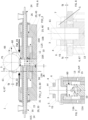
- FIG. 1 illustrates, in a perspective view, an example of an installation according to the invention, in an opening configuration in which the first and second head modules, which here each carry an extruder, are moved back at a distance from the first bearing and the location provided for the tooling module.
- FIG 2 illustrates the installation of the figure 1 , in the opening configuration, according to a sectional view in a plane called the “frontal plane” which contains the engagement direction and the coupling direction, and which is here normal to the axis of rotation of the roller.
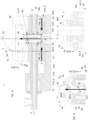
- FIG 3 illustrates the installation of the figures 1 And 2 according to a sectional view in a plane called the "sagittal plane", which is here normal to the coupling direction and which contains the direction of engagement as well as the axis of rotation of the roller; said sagittal plane divides the installation into two parts which are substantially or even exactly symmetrical to each other.
- FIG 4 illustrates the installation of the figures 1 And 2 according to a sectional view in a secondary sectional plane which is parallel to the sagittal plane and which here passes through the solid portion of the upper branch of a retaining hook which is associated with the first head and arranged to engage the first bearing in order to retain said first bearing against the preload force.
- FIG. 5 illustrates, in a perspective view, the installation of the Figures 1 to 4 in a pre-positioning configuration, according to which the first and second head modules have been brought closer to each other, on either side of the location intended for the tool block, so as to define between them a passage for the tool module, and in which the respective retaining hooks of said first and second head modules have come to be placed opposite the first bearing, here above the lateral extensions of the sole of said first bearing, to form stops intended to limit the movement of said first bearing in the direction of engagement.
- figure 6 illustrates, according to a sectional view in the frontal plane, the installation of the figure 5 in pre-positioning configuration.
- FIG. 7 illustrates the installation of the figures 5 And 6 according to a sectional view in the sagittal plane.
- FIG 8 illustrates the installation of the figures 5 And 6 according to a detailed sectional view in the secondary sectional plane, showing the clearance known as “preload clearance” which initially separates, according to the direction of engagement, the first bearing from the stops formed by the retaining hooks which equip the first and second head modules.
- FIG. 9 illustrates, in section in the frontal plane, the installation of the preceding figures at the end of an approach phase according to which the tooling module has been brought, by displacement in the direction of engagement, into the space between the first and second head modules, in contact with the first bearing, so as to place the die at a distance from the roller which is appropriate to the desired height for the air gap.
- FIG 10 illustrates the installation of the figure 9 according to a sectional view in the sagittal plane.
- FIG 11 illustrates the installation of the Figures 9 and 10 according to a detailed view in the secondary section plane, on which it can be seen on the one hand that the tool block has come into contact with a docking stop which is integral with the first bearing, so as to bear on said first bearing, and on the other hand that the preload clearance which separates the sole of the first bearing from the retaining hook is still present, so as to form a travel reserve in the engagement direction to allow a slight additional movement of the tool module and the first bearing as a whole, during a subsequent preload phase.
- FIG 12 is a partial perspective view of the installation of the preceding figures, in an engagement configuration, which results from a preloading phase having followed the approach phase, and according to which the tooling module, positioned at a distance from the roller which corresponds to the desired air gap, exerts a preloading force against the first bearing, in the engagement direction, thus pressing the sole of said first bearing into abutment against the retaining hooks which equip the first and second head modules, themselves still in the pre-positioning configuration.
- FIG 13 is a partial view of the installation of the figure 12 in engagement configuration, according to a sectional view in the frontal plane which shows the action of preload actuators having ramps which come to stress the tool module, and, by means of said tool module, the first bearing, to bring the first bearing into abutment against the retaining hooks and generate the desired preload force in the engagement direction.
- said preload actuators act in gripping zones which are located at one end of said tool module which is located opposite the end which carries the die and which cooperates with the roller to form the air gap.
- FIG 14 is a detailed view of the installation of the figures 12 And 13 , in section in the sagittal plane, which shows the lifting of the first bearing under the effect of the thrust exerted by the tool module driven by the preload actuators during the preload phase, as well as the translational guidance in the direction of engagement, here vertical, of said first bearing along two posts provided for this purpose.
- FIG. 15 is a partial view of the installation of the Figures 12 to 14 , in section in the secondary section plane, and which shows the take-up of the play for preload obtained by the action of the preload actuators which push and hold the tool module, and therefore the first bearing driven by said tool module, against the retaining hooks, in the direction of engagement.
- FIG 16 illustrates, in a partial sectional view in the frontal plane, the installation of the preceding claims in a closed configuration according to which the first head module and the second head module have been brought into abutment against the tooling module, in opposition to each other on either side of said tooling module, and thus exert against said tooling module a clamping force in order to maintain by pinching said tooling module in its engagement configuration, and to ensure sealed communication between the extruders and said tooling module, so as to be able to convey the extruded materials from the extruders to the die and to the air gap, through said tooling module, to produce the desired profile.
- FIGS. 17 and 18 illustrate, according to sectional views in the secondary section plane, the installation of the preceding figures in the closed configuration, respectively before and after the engagement of stabilizing wedges which are each inserted between the sole of the first bearing and one of the retaining hooks in order to block and constrain the first bearing in a direction transverse to the axis of rotation of the roller and parallel to the coupling direction, so as to laterally stabilize said first bearing and said roller and to avoid any flexion deflection of the posts, and thus so as to prevent any lateral deviation of the roller relative to the die during the profile generation operation.
- stabilizing wedges which are each inserted between the sole of the first bearing and one of the retaining hooks in order to block and constrain the first bearing in a direction transverse to the axis of rotation of the roller and parallel to the coupling direction, so as to laterally stabilize said first bearing and said roller and to avoid any flexion deflection of the posts, and thus so as to prevent any lateral deviation of the roller relative to the die during the profile generation operation.
- FIG 19 is a partial perspective view of the installation of the figure 18 , with the stabilizer wedges engaged between the first bearing and the retaining hooks carried by the first and second head modules.
- FIG. 20 illustrates the installation of the Figures 18 and 19 according to a top view.
- FIGS. 21 and 22 illustrate, respectively according to partial sectional views respectively in the frontal plane and in the sagittal plane, the installation of the preceding figures in the closed configuration, during the extrusion of a profile.
- FIG 23 illustrates, according to a sectional view in the frontal plane, the installation of the preceding figures in a first reopening phase where the first and second head modules are moved away from each other to release them, with their respective extruders, from the tooling module.
- FIG 24 illustrates, according to a sectional view in the frontal plane, the installation of the preceding figures, in a second reopening phase during which the tooling module is moved away from the roller, here by lowering said tooling module, so as to move said tooling module into a release configuration.
- FIG 25 illustrates, according to a sectional view in the frontal plane, the installation of the preceding figures, in a third and final reopening phase, during which the preload actuators are retracted, here inside the first and second head modules, to find the opening configuration presented in the figure 1 .
- FIGS. 26A, 26B, and 26C illustrate, according to detailed perspective views, the successive stages of implementation of a locking mechanism, applicable in particular to the installation according to the Figures 1 to 25 , said locking mechanism comprising a first and a second jaw which each engage the first head module and the second head module to force the bringing together of said first and second head modules and the generation of the clamping force which said head modules exert on the tool module.
- FIG. 27 illustrates, according to a detailed top view in section in a plane, here a plane normal to the engagement direction Z and which contains the coupling direction and the direction of movement of the jaws, called the “locking direction”, the engagement of ramps provided on the branches of the first jaw along corresponding counter-ramps provided in the first and second head modules, the inclination of said ramps and counter-ramps making it possible to convert a force for bringing the jaws together, carried by the locking direction, into a clamping force carried by the coupling direction, transverse to the locking direction and making it possible to force the mutual coming together of said first and second head modules, in compression, against the tool block.
- the present invention relates to an extrusion installation 1 intended to produce a profile 2, shown diagrammatically in dotted lines on the Figures 21 and 22 , as well as a method for implementing such an installation 1, which method makes it possible in particular to prepare such an extrusion installation 1 for producing such a profile 2.
- extrusion plant 1 includes roller 3.
- Said roller 3 has a shape of revolution, preferably a shape of a right cylinder, around a central axis Y3.
- the radially external surface of said roller 3 serves as a receiving surface 3A for receiving, cooling and dimensionally stabilizing the profile 2, as the latter is produced.
- the roller 3 can be provided with a thermal regulation system, comprising for example heat transfer fluid circulation channels, in particular making it possible to cool said roller.
- the roller 3 is supported in rotation, around its central axis Y3, by at least one first bearing 4.
- the roller 3 comprises, projecting axially relative to the receiving surface 3A, on either side axially of said receiving surface 3A, a first axial extension 6 and a second axial extension 7 which materialize the central axis Y3 of rotation.
- the first axial extension 6 cooperates in a pivot connection with the first bearing 4.
- the second axial extension 7 cooperates in a pivot connection with a second bearing 5.
- the presence of two bearings 4, 5 arranged axially on either side of the roller 3 gives said roller 3 particularly robust, balanced and stable rotational guidance.
- the considerations relating to the first level 4, in particular the arrangements, functions and movements described in connection with the first level 4, may advantageously be applied mutatis mutandis to the second level 5.
- the roller 3 may preferably have a diameter of between 0.5 m and 10 m, for example between 0.90 m and 3 m.
- the frontal plane denoted PF
- PF is considered to be the plane which is normal to the axis Y3 of the roller and which intersects said roller 3 in its middle, that is to say at mid-distance axially between the first axial extension 6 and the second axial extension 7.
- the installation 1 is arranged so that the frontal plane PF and the sagittal plane PS are vertical.
- the installation 1 also comprises a tooling module 10 which comprises a die 11 which is intended to cooperate with the roller 3, and more particularly which is intended to cooperate with the receiving surface 3A of said roller 3, to form an air gap 12 making it possible to shape the profile 2.
- a tooling module 10 which comprises a die 11 which is intended to cooperate with the roller 3, and more particularly which is intended to cooperate with the receiving surface 3A of said roller 3, to form an air gap 12 making it possible to shape the profile 2.
- the die 11 preferably has for this purpose an end face 11A which partially covers the roller 3, over a determined angular sector around the central axis Y3 of said roller, and which has a curved shape concave relative to the central axis Y3 of the roller, which shape is substantially conjugated to the shape of the receiving surface 3A of the roller.
- said end face 11A has the shape of a right cylinder, centered on said central axis Y3.
- the height H12 of the air gap 12 will be designated as the maximum distance, considered radially to the central axis Y3 of the roller, and therefore perpendicular to the receiving surface 3A of said roller, which separates the terminal face 11A of the die from the receiving surface reception 3A of the roller, in the area where the die 11 and the roller 3 overlap each other in order to form walls intended to be in contact with the extruded material to delimit the thickness H2 of the profile 2.
- the height H12 of the air gap 12 corresponds to the maximum height which is observed, over the width of said air gap 12, and therefore over the width W2 of the profile, at the level of the exit of said air gap 12, that is to say at the location where the die 11 is interrupted and therefore ceases to cover the receiving surface 3A of the roller 3 in azimuth around the central axis Y3, as is notably visible on the figures 9, 10 , 13, 14 , 21 and 22 .
- the useful width W11 of the end face 11A of the die considered axially, that is to say in the direction of the central axis Y3 of the roller, as is visible on the figures 3 , 10 , 14 And 22 , that is to say the width of the end face 11A of the die which will delimit, with the receiving surface 3A of the roller, the air gap 12 traveled by the extruded material constituting the profile, which will therefore be in contact with the extruded material to delimit the transverse section of the profile 2, and which consequently defines the width W2 of said profile 2 as is notably visible on the figure 22 , preferably covers at least 50%, and for example between 50% and 90% of the useful axial width W3 of said roller 3, that is to say of the axial width of the receiving surface 3A of the roller.
- the installation 1 further comprises at least one first head module 13 which carries at least one first extruder 14 intended to provide a first material constituting the profile 2.
- Said first extruder 14 preferably comprises a screw 15 which is driven in rotation about its longitudinal axis X15 in a sleeve 16, which sleeve 16 is fixed to said first head module 13.
- the sheath 16 is preferably provided, in an upstream portion, with an inlet orifice 16_in, for example in the form of a hopper, allowing the material to be worked to be introduced, and, in a downstream portion, with a downstream outlet orifice 16_out which allows the material worked by the screw 15 of the extruder to exit said sheath 16.
- an inlet orifice 16_in for example in the form of a hopper, allowing the material to be worked to be introduced, and, in a downstream portion, with a downstream outlet orifice 16_out which allows the material worked by the screw 15 of the extruder to exit said sheath 16.
- Said output port 16_out is arranged so as to be able to be placed, as is notably illustrated in the figure 21 , in sealed communication with the tool block 10 so as to be able to deliver to the die 11, via one or more channels 17 provided for this purpose in the tool block 10, the material which is extruded by the extruder 14.
- the profile 2 is preferably made from at least one rubber-based material (or “mixture”).
- profile 2 will be formed from a single layer of a single homogeneous material, based on rubber.
- the profile 2 will preferably be made from several materials of different compositions, based on rubber, said several rubber-based materials each being worked by at least one dedicated extruder 14, 24, conveyed through the tooling module 10, then brought together, ordered and shaped by the die 11 and the air gap 12 into a profile 2, according to a desired arrangement.
- compositions of the different materials which are juxtaposed in the cross section of the profile 2, as well as the positions and dimensions of the locations of said materials in the cross section of the profile will of course be predefined according to the destination of said profile 2.
- said profile 2 is preferably intended to form a constituent of a pneumatic tire, for example a tread, a sidewall, or even, in particular if said profile is particularly thin, a rubber ply intended to form an interface between two plies which overlap within the pneumatic tire.
- the profile 2 is advantageously produced continuously in the direction of its length, which defines a direction called “longitudinal direction” L2.
- said longitudinal direction L2 is parallel to the frontal plane PF, and preferably contained in the frontal plane PF.
- the profile 2 presents, as is visible on the figure 22 , a first dimension W2, considered in a direction parallel to the central axis Y3 of the roller 3 and corresponding to the width W2 of said profile, and a second dimension H2, considered radially relative to the central axis Y3, and therefore perpendicular to the receiving surface 3A of the roller, and which corresponds to the thickness H2 of said profile 2.
- the thickness H2 of the profile is defined by the height H12 of the air gap, and, taking into account in particular possible swelling phenomena linked to the release of pressure constraints at the air gap outlet, said thickness H2 of the profile, finished and stabilized, can generally represent between 50%, in particular if the speed of the roller 7 causes a stretching of the profile 2 at the outlet of the die, and 200% of the height H12 of the air gap 12, considered at the outlet of said air gap 12, that is to say at the location where the die 11 ceases to cover the receiving surface 3A of the roller 3.
- the invention thanks to the precision that it allows to be obtained in the mechanical definition of the air gap 12, allows to produce profiles 2, and in particular single-material profiles, which are particularly thin, and for example which have a final thickness H2 of between 0.1 mm and 0.5 mm.
- profiles 2 in a wide range of thicknesses, for example profiles whose thickness H2 is between 0.1 mm, which corresponds where appropriate to the thinnest thickness achievable by the installation, and 150 mm, which corresponds where appropriate to the maximum thickness achievable by said installation 1.
- the width of the profile W2, strictly greater than its thickness H2 may be between 1 cm and 150 cm.
- the unit width W2 of the profile 2 allows it, and in particular for profiles with a width of between 1 cm and 10 cm or even 20 cm, several separate profiles 2 may be extruded simultaneously, in parallel side by side, through the same tooling module 10 and on the same roller 3.
- the width W2 of the profile may be between 1 cm and 150 cm.
- the ratio W2/H2 between the width W2 and the thickness H2 may thus preferably be between 100 times and 3,000 times.
- the method comprises an engagement step (s1), which constitutes a “first step” of the closing sequence, engagement step (s1) during which moves the tool module 10 relative to the first head module 13 and to the first bearing 4 in a first direction Z called the “engagement direction” Z, so as to bring said tool module 10 into abutment against the first bearing 4 ( figures 9, 10, 11 ), here therefore to place the tool module 10 in abutment against the bearing 4 carrying the roller 3, and to subject said tool module 10 to a preload force F_Z which is oriented in the direction of engagement Z and against the first bearing 4 ( figures 12 , 13, 14, 15 ), so as to place said tooling module 10 relative to the roller 3, and more particularly to place the end face 11A of the die 11 relative to the receiving surface 3A of the roller 3, in a configuration called the “engagement configuration” which defines the air gap 12 desired to produce the profile 2.
- the docking stop 18 will guarantee the precision and reproducibility of the height H12 of the chosen air gap 12.
- the air gap 12 thus obtained in the engagement configuration will have a height H12, considered radially relative to the roller 3, which is between 0.1 mm and 150 mm, and for example between 0.1 mm and 0.5 mm to produce thin profiles, in particular profiles whose final thickness, after cooling and stabilization, will be between 0.2 mm and 0.3 mm.
- the thickness of the profile 2 may vary, and if necessary be adjusted in a controlled manner, depending on the one hand on the possible degree of longitudinal stretching that is exerted on the profile 2 with the roller 3, stretching which tends to reduce the thickness of the profile, and on the other hand on the natural tendency of the material to "swell", that is to say to increase in volume, which tends to spontaneously increase the thickness of the profile once it has left the air gap 12.
- the distance DZ between the receiving surface 3A of the roller and the end face 11A of the die will be, as is notably visible on the figure 24 , strictly greater than that observed in the engagement configuration, and will preferably be equal to or greater than 20 cm, or even equal to or greater than 50 cm, so as to provide sufficient clearance of the tooling module 10 relative to the roller 3 to allow easy access to the receiving surface 3A of the roller 3, and, if necessary, allow cleaning of the roller 3 and/or easy cleaning or replacement of the tooling module 10.
- the engagement direction Z is contained in the sagittal plane PS, and, more preferably, corresponds to the line of intersection of the frontal plane PF with the sagittal plane PS.
- the engagement direction Z is vertical, or at least substantially vertical, for example within a tilt range of +10 degrees to -10 degrees from the vertical.
- the engagement movement MZ+ respectively the removal movement MZ-
- the removal movement MZ- will preferentially correspond to a predominantly or even exclusively vertical movement, typically in vertical translation.
- the engagement movement MZ+ will be carried out in rectilinear translation, parallel to the engagement direction Z.
- the engagement device 19 may comprise any conveyor mechanism 20 which makes it possible to transport the tool module 10 in the engagement direction Z, preferably in rectilinear translation, from its release configuration to its engagement configuration and vice versa.
- the engagement device 19 comprises a conveyor mechanism 20 formed by an elevator 20 which makes it possible to transport the tool module 10 in the vertical engagement direction Z, in order to, alternately, execute an upward advance movement (engagement movement MZ+) by raising said tool module 10 to bring it closer to the roller 3, or on the contrary execute a downward backward movement (movement away movement MZ-) by lowering said tool module 10 to move it away from the roller 3 and the docking stop 18 of the first bearing 4.
- the conveyor mechanism 20 will be likened to an elevator 20 in the following.
- the engagement device 19 will preferably comprise at least one, and preferably two, preload actuators 21, 22, arranged so as to be able, when the tool module 10 is in contact with the docking stop 18 of the first bearing 4, to accentuate the compression force exerted by the tool module 10 against said docking stop 18, and therefore more generally against the first bearing 4, and thus generate the desired preload force F_Z, as illustrated in the Figures 13 and 14 .
- these preload actuators 21, 22 may preferably comprise slope sliders, which are mounted to move in a direction transverse to the engagement direction Z, driven for example by jacks or any other suitable motorization system, and which engage the tool module 10, by performing feed movements here noted FM_21 and FM_22 on the figure 13 .
- the preload actuators 21, 22 engage the tooling module 10 by the base or "yoke" of said tooling module 10, which is located at the end opposite the end having the die 11.
- the elevator 20 on the one hand, and the preload actuators 21, 22 on the other hand will preferably be arranged so as to have a differential and complementary action, in that the elevator 20 will be able to carry out a movement of the tool module 10 in the engagement direction Z within the limit of a predetermined maximum amplitude stroke, called "large amplitude", sufficient to bring the tool module 10 from its release configuration to the configuration in which said tool module 10 comes into contact with the docking stop 18, while the preload actuators 21, 22 will then take over to continue the engagement movement MZ+ in this same engagement direction Z, over a stroke which will be of amplitude strictly less than the large amplitude of the elevator 20, but on the other hand being capable of generating a strong stress against the tool module 10. and the docking stop 18, so as to be able to achieve the desired preload force F_Z.
- a predetermined maximum amplitude stroke called "large amplitude”
- the elevator 20 will preferably operate a first phase of the engagement step (s1), corresponding to an approach phase (s1_1), by ensuring most of the amplitude of the movement necessary for the engagement movement MZ+, but by only being capable of generating a relatively moderate preload stress, less than the targeted preload force F_Z, while the preload actuators 21, 22 will then complete the engagement step (s1) by performing a second phase, called the “preload phase” (s1_2), by having only a low capacity for moving the tool module 10 in the engagement direction Z, but a high capacity for generating a stress in the engagement direction Z, making it possible to achieve the desired intensity of the preload force F_Z.
- a second phase called the “preload phase” (s1_2)
- said preload actuators 21, 22 will be supported, unlike the elevator 20, by the head module(s) 13, 23.
- the preload force F_Z is preferably between 300 kN and 1,500 kN, or approximately the equivalent of 30 tonnes to 150 tonnes.
- the preload force could be of the order of 600 kN, or approximately 60 tonnes.
- such a preload intensity makes it possible to sufficiently prestress the tooling module 10 and its die 11 against the first bearing 4, and therefore against the roller 3 carried by said first bearing 4, to be able to subsequently compensate at least partially, or even totally, the effects which will be produced by the pressure stresses generated in the air gap 12 by the flow of the extruded materials during the production of the profile 2.
- the method then comprises, after the engagement step (s1), a tightening step (s2), which constitutes a “second step” of the closing sequence, and during which, while said tool module 10 is in its engagement configuration, prestressed against the first bearing 4 by the preload force F_Z, as illustrated in the Figures 12 to 15 , we come, as illustrated on the figure 16 , clamping said tooling module 10 between the first head module 13 provided with the first extruder 14 and a second head module 23 distinct from the first head module 13, by bringing said first head module 13 and the second head module 23 closer to each other, on either side of the tooling module 10, in a second direction X called the “coupling direction” X which is transverse to the engagement direction Z, preferably perpendicular to said engagement direction Z, so as to put the first extruder 14 into communication with the tooling module 10, and by subjecting said first and second head modules 13, 23 to a clamping force F_X which is oriented in said coupling direction X, so as to hold the tool
- the tool module 10 is thus firmly gripped in a vice between, and by, the first head module 13 and the second head module 23, which each support on the tooling module 10, in opposition to each other in the coupling direction X.
- the tooling module 10 is therefore firmly held by the first and second head modules 13, 23 in a fixed position relative to the first bearing 4 and to the central axis Y3 of the roller, which makes it possible to keep the arrangement of the air gap 12 constant during the production of the profile 2.
- the dimensions of the air gap 12, and in particular the height H12 of said air gap are almost insensitive to the intensity of the pressure at which the material is delivered by the die 11 into the air gap 12, and therefore almost or even totally invariant during the extrusion process making it possible to generate the profile 2.
- Said profile 2 consequently has great regularity, in particular as regards its thickness H2.
- the installation 1 comprises a coupling device 29 which gives the first head module 13 and/or the second head module 23 their own mobility relative to the first bearing 4 and relative to the tool module 10 in the coupling direction X, transverse to the engagement direction Z.
- transverse or “transversely oriented” is indicated, in the general sense of such an expression, that a direction is arranged obliquely, preferably perpendicularly, relative to a reference direction.
- the engagement direction Z and the coupling direction X will be concurrent and will be substantially perpendicular, that is to say that they will form between them an angle of between 70 degrees and 110 degrees, preferably between 80 degrees and 100 degrees, preferentially between 85 degrees and 95 degrees, or even preferentially exactly perpendicular, that is to say that they will form between them an angle equal to 90 degrees.
- the coupling direction X is preferably contained in the frontal plane PF. Even more preferably, said frontal plane PF is the plane defined by the engagement direction Z and by the coupling direction X.
- Y the direction parallel or even coincident with the axis of the roller Y3 and which forms with the coupling direction X and the engagement direction Z a right-angled trihedron.
- a coupling direction X and an engagement direction Z which are crossed, preferably perpendicular, makes it possible to distribute the various components of the installation 1, including in particular the elevator 20 of the engagement device which makes it possible to move the tooling module 10, the head modules 13, 23, their respective extruders 14, 24 and their coupling device 29, in different directions of space, relative to the roller 3, to the air gap 12, around the location, called the “core location” 60, which the tooling module 10 occupies in the engagement configuration. It is thus possible to simultaneously optimize the compactness of the installation 1 while guaranteeing excellent accessibility to the various components of said installation 1.
- the coupling direction X will preferably be substantially or even exactly horizontal, in particular when the engagement direction Z is substantially or even exactly vertical.
- the coupling direction X will preferably form an angle of less than 20 degrees, preferably less than 10 degrees, more preferably less than 5 degrees, or even equal to zero degrees relative to the horizontal.
- the horizontality of the coupling direction X will advantageously offer great stability, and will make it possible to limit the expenditure of energy, when moving the first head module 13 and/or the second head module 23, which constitute particularly heavy elements.
- Such an arrangement will further facilitate access to the extruder 14 for cleaning or material supply operations, insofar as, in particular, when the first head module 13 and its extruder 14 move in the coupling direction X, they remain at all times at a substantially constant altitude, and therefore at the working height of the operator.
- first connection face 13A of the first head module 13 and the second connection face 23A of the second head module 23 are preferably parallel to each other, and preferably, in addition, parallel to the engagement direction Z.
- the joint planes according to which the head modules 13, 23 press in a sealed manner against the tool module 10 in the closed configuration are thus preferably flat surfaces, parallel to each other and parallel to the engagement direction Z, and normal to the coupling direction X, which simplifies the opening and closing movements, and increases the stability of the closing configuration.
- the tooling module 10 comprises a plurality of plates which are stacked in the direction of their thickness according to the coupling direction X, and whose faces of larger dimensions are flat and parallel to the first receiving face 10A and to the second receiving face 10B, and therefore preferably parallel to the engagement direction Z.
- the visible face of the first plate of the stack forms the first receiving face 10A
- the visible face of the last plate of the stack forms the second opposite receiving face 10B.
- the die 11 is advantageously located on a face of the stack of plates, and more generally of the tooling module 10, which is secant, or even perpendicular, to the receiving faces 10A, 10B.
- the die 11 is located, and opens, on the upper edge of the tooling module 10.
- the elbow angle of the channels 17 advantageously makes it possible to transfer each extruded material from the receiving face 10A, 10B concerned to the die 11 and its end face 11A.
- the first head module 13, and preferably each of the first and second head modules 13, 23, may carry one and only one extruder 14, 24.
- the first head module 13, and/or, similarly, the second head module 23 may carry several extruders, and thus preferably supply as many distinct channels 17 within the tooling module 10.
- each extruder 14, 24 will preferably open onto the connection face 13A, 23A of the head module 13, 23 which carries the extruder concerned, opposite an intake orifice which forms the inlet of a corresponding channel 17 provided in the tooling module 10.
- each head module 13, 23 will preferably comprise, for connecting the barrels 16, 26 of the extruders to its connection face 13A, 23A, as many paths, preferably separate from each other, as said head module 13, 23 can accommodate separate extruders 14, 24.
- only one of the head modules 13, 23 is movable relative to the first bearing 4 and relative to the tool module 10 in the coupling direction X, the other head module 23, 13 being fixed in said coupling direction X, such that the movement of only the movable head module 13 against the tool module 10 and the other fixed head module 23 would be sufficient to reach the closing configuration and to generate the clamping force F_X.
- the coupling device 29 gives each of the first and second head modules 13, 23 their own mobility in the coupling direction X, relative to the first bearing 4 (and, likewise, relative to the second bearing 5) and relative to the tool module 10.
- the first head module 13, located on a first side of the sagittal plane PS is able to move in the coupling direction X, preferably in rectilinear translation in said coupling direction X, so as to be able to alternately approach said sagittal plane PS, the tooling module 10, and the second head module 23, until it can engage said tooling module 10, according to an advance movement FM_13 ( figure 6 ), or move away from said sagittal plane PS, from the tool module 10, and from the second head module 23, in particular in order to disengage from the tool module 10, according to a backward movement BM_13 ( figure 23 ), while, likewise, the second head module 23, which is located on the other side of the sagittal plane PS, is also able to move in the coupling direction X, preferably in rectilinear translation in said coupling direction X, and preferably independently of the movements of the first head module 13, so as to be able to alternately approach said sagittal plane PS, of the tool module 10, and of the first head
- the forward movements FM_13, FM_23, respectively the backward movements BM_13, BM_23, of the first and second head modules 13, 23, although preferably potentially controllable independently from one head module 13 to the other head module 23, are nevertheless preferably synchronized, in particular during closing, so that the first head module 13 and the second head module 23 are preferably moved simultaneously, substantially mirroring each other relative to the sagittal plane PS, according to movements which are therefore carried out in opposition to each other.
- the coupling device 29 comprises at least one first carriage 30 which carries the first head module 13, or which is formed in one piece with said first head module 13, and which is mounted movably and guided in translation along a first rail 31, preferably rectilinear, and preferably horizontal, which thus materializes the coupling direction X.
- Said frame 32, and consequently the first rail 31 which is integral with said frame 32, is preferably fixed to the floor of the workshop in which the installation 1 is installed.
- the first carriage 30 is guided in translation on a pair of first rails 31 parallel to each other.
- the first carriage 30 can be propelled by any suitable drive means 33, such as an electric motor or a cylinder 33, preferably a hydraulic cylinder, for example an annular cylinder 33 housed in the frame 32.
- Said drive means 33 will advantageously be controlled by a control unit, preferably electronic.
- the useful travel of the first carriage 30, and therefore of the first head module 13, which separates the contact position P13_3 from the fully open position P13_1 along the coupling direction X, and which is here denoted DX13 will be equal to or greater than 50 cm, and for example between 1 m and 2 m, and this in particular in order to provide sufficient clearance to allow an operator to easily access the first connection face 13A of the first head module 13, the first extruder 14, and where appropriate the core location 60 and the receiving surface 3A of the roller, when the installation is in the opening configuration.
- the setback distance can be chosen to be simply non-zero, for example equal to or greater than 0.5 mm, or even equal to or greater than 1 mm.
- the coupling device 29 preferably comprises at least one second carriage 40 which carries the second head module 23, and which is mounted movably and guided in translation along a second rail 41, preferably a pair of second rails 41.
- Said second rail 41, or each of said second rails 41 is preferably rectilinear, and preferably horizontal, and is, just like the first rail 31, mounted on the frame 32 and also materializes the coupling direction X.
- the second rail 41 is aligned with the first rail 31, in the extension of said first rail 41, in a common direction which corresponds to the coupling direction X.
- the propulsion of the second carriage 40 is preferably ensured by a second cylinder 43, advantageously distinct from the first cylinder 33, and potentially controllable independently.
- the characteristics related to the movements FM_23, BM_23, possible positions P23_1, P23_2, P23_3 and useful stroke length applicable to the second carriage 40 and to the second head module 23 can be deduced mutatis mutandis from the characteristics described above with reference to the first carriage 30 and to the first head module 13, by symmetry with respect to the engagement direction Z, and more particularly, where appropriate, by plane symmetry with respect to the sagittal plane PS.
- the coupling device 29 comprises, as can be seen in the Figures 26A, 26B, 26C and 27 , a locking mechanism 50 comprising a first jaw 51 and a second jaw 52 which are mounted to move in a third direction Y which is transverse, and preferably perpendicular, to the first engagement direction Z and transverse, and preferably perpendicular, to the second coupling direction X.
- Said first jaw 51 and said second jaw 52 are arranged so that, when the tool module 10 is in the engagement configuration, they can approach each other, on either side of the tool module 10, in said third direction Y, so as to each engage with, on the one hand, the first head module 13 and, on the other hand, the second head module 23 so as to force the mutual approach and the tightening, in the coupling direction X, of said first and second head modules 13, 23 against the tool module 10, in order to place the installation 1 in the closing configuration.
- Each jaw 51, 52 is preferably self-propelled, in that on the one hand said jaw 51, 52 carries at least one motor 53, preferably formed by a jack 53, and preferably a series of motors 53, preferably formed by jacks 53, said motors 53 being distributed preferably in two rows, at a rate of one row facing each head module 13, 23, and that on the other hand each motor 53 acts on a tie rod 54, preferably oriented parallel to the third direction Y, said tie rod 54 coming into contact with the third direction Y. taken in an anchoring point 55, of the notch type, provided in the corresponding head module 13, 23, so as to be able to force the approach in traction FM_51, FM_52 of the lock 51, 52 against the first and second head modules 13, 23.
- the tie rod 54 can advantageously be formed by the rod of the jack 53, for better compactness.
- the multiplication of 53 motors advantageously makes it possible to exert a high intensity tractive effort while keeping 53 motors compact and relatively light.
- the docking stop 18 may be adjustable, for example by means of a set of interchangeable shims, such as spacers, so that the operator can choose, before initiating the closing of the installation 1, the distance from the axis of the roller Y3 at which said docking stop 18 must intercept and stop the tooling module 10, and therefore so that the operator can choose and adjust the height H12 of the air gap 12 according to production needs.
- a set of interchangeable shims such as spacers
- the second bearing 5 also comprises, in a similar manner, a docking stop 18.
- the tool module 10 comes, preferably simultaneously, and more preferably at the same altitude in the engagement direction Z, to bear against each of the two docking stops 18, which are secured respectively for the first to the first bearing 4, and for the second to the second bearing 5, and which are therefore distributed axially on either side of the roller 3, and more particularly on either side of the frontal plane PF, as is notably visible on the figures 3 , 7 , 10 And 14 .
- first bearing 4 and the second bearing 5 are moved simultaneously in the engagement direction Z by the tool module 10, during the preload phase (s1_2), in a well-balanced manner on either side of the frontal plane PF, which makes it possible to maintain constant the orientation, and more particularly here the horizontal attitude, of the central axis Y3 of the roller during said preload phase (s1_2).
- the first retaining member 61 is preferably doubled, that is to say arranged so as to be able to intercept and simultaneously block the first bearing 4 on the one hand, and the second bearing 5 on the other hand, on either side of the roller 3 and the frontal plane PF.
- the docking stops 18 are located, along the engagement direction Z, here vertical, at an intermediate distance (here an intermediate altitude) which is strictly between the central axis Y3 of the roller and the part of the tool module 10 furthest from said central axis Y3.
- said first and second bearings 4, 5 will preferably be provided respectively with a first slide 62 and a second slide 63, each guided in translation in the engagement direction Z, respectively in a first post 64 and a second post 65 which are both integral with the frame 32, as is notably visible on the figures 1 , 3 , 10 , 12 And 14 .
- the first and second preload actuators 21, 22 may be formed by sliders, which are mounted movably and guided in translation in the coupling direction X, within the first head module 13 and respectively the second head module 23.
- Said preload actuators 21, 22 may each be provided with a ramp 21A, 22A.
- the preload actuators 21, 22 will form wedges which can alternately either be retracted into a rest position ( figures 2 , 6 , 9 ) within their respective head module 13, 23, set back from the corresponding connection face 13A, 23A relative to the core location 60, relative to the tooling module 10, and relative to the sagittal plane PS, or on the contrary be pushed into projection from the connection face 13A, 23A of their head module 13, 23 ( figure 13 ), by a differential advance movement FM_21, FM_22 relative to the carriages 30, 40 carrying the head modules 13, 23, so as to engage their ramp 21A, 22A against the tool module 10, and thus tend to force the approach then causes the compression in preload F_Z of the tool module 10 against the first bearing 4, and the first retaining member 61.
- Said preload actuators 21, 22 may be driven by any suitable drive means, such as a motor or cylinder, electric or hydraulic, preferably mounted on the head module 13, 23 concerned.
- the first and second preload actuators 21, 22 will act in opposition to each other, mirrored on either side of the tool module 10 and the sagittal plane PS containing the engagement direction Z, emerging respectively from the first head module 13 and the second head module 23, so as to exert a balanced action on the tool module 10, and thus maintain the attitude of said tool module 10 relative to the engagement direction Z.
- the distance JZ called “preload clearance” JZ which initially separates, before the execution of the preload phase (s1_2), the first bearing 4 from the first retaining member 61 in the engagement direction Z, as is visible on the figures 5 , 6 , 8 And 11 , and which therefore forms the distance which is traveled by the first bearing 4 in said engagement direction Z during said preload phase (s1_2), is between 0.1 mm and 1 mm.
- this slight clearance for preload JZ offers the mobile assembly formed by the tool module 10 and the first and second bearings 4, 5 a stroke which is both sufficiently long to allow the preload actuators 21, 22 to properly execute their advance movement FM_21, FM_22 according to the direction coupling X and to generate an overall upward movement MZ+ making it possible to take up any play present within the moving assembly, and nevertheless sufficiently short to be quickly compensated by a sliding of the tool module 10 on the ramps 21A, 22A of low slope.
- the first retaining member 61 is integral with the first head module 13.
- the head module 13 can serve as an anchor for the first retaining member 61, and retain said first retaining member 61 (at least) in the engagement direction Z, in order to prevent said retaining member 61 from moving in said engagement direction Z under the thrust of the preload actuators 21, 22.
- said first retaining member 61 is thus preferably mounted on the first carriage 30 which is used to move the first head module 13 in the coupling direction X, such that said first carriage 30 drives the first retaining member 61 integrally with the first head module 13 in the forward movements FM_13 and backward movements BM_13 of said first head module 13 in said coupling direction X.
- the first retaining member 61 occupies, on the first head module 13, a position which is fixed, at least in the engagement direction Z, more preferably which is fixed both in the engagement direction Z and in the coupling direction X, or even more preferably which is fixed in all three main directions X, Y, Z of space, relative to the first connection face 13A of said first head module 13.
- the operation of the first retaining member 61 during the closing sequence of the installation 1 will thus be particularly predictable, precise, and reproducible.
- the first retaining member 61 may be formed in one piece with the portion of the first head module 13 which forms the first connection face 13A, in order to guarantee the rigidity and robustness of said retaining member 61.
- the retaining member 61 may be formed by an attached part and fixed, for example screwed, onto the first head module 13, so as to be immobilized relative to the first connection face 13A.
- the action of generating the preload force F_Z by engaging the preload actuators 21, 22 against the tool module 10 therefore amounts to pinching, in the engagement direction Z, said tool module 10 and the first and second bearings 4, 5 in a vice between two jaws which are supported by the same head module 13, and more particularly by the same carriage 30, namely a first jaw, here forming a fixed jaw in the engagement direction Z, and which is here formed by the first retaining member 61, and a second jaw, here forming a movable jaw, and which is formed by the ramp 21A, 22A of the preload actuator 21, 22 which is located substantially directly above the retaining member 61.
- the tooling module 10 to the bearings 4, 5, by means of the first head module 13 (and more preferably by means of the first and second head modules 13, 23), at least in the engagement direction Z.
- the first retaining member 61 may have any suitable shape, such as a shoulder, allowing it to be placed on the trajectory taken by the first bearing 4 in the engagement direction Z during the engagement step (s1).
- said first retaining member 61 forms a hook, preferably in the shape of a C.
- the concave opening of said hook is directed towards the sagittal plane PS, to face the bearings 4, 5 in the coupling direction X.
- the first retaining member 61 is arranged so as to come to be placed on the trajectory of the first bearing 4 (i.e. on the trajectory that said bearing will take when performing the upward movement MZ+) when the first head module 13 passes, following the coupling direction X, from its fully open position P13_1 ( figures 1 And 2 ) at its intermediate position P13_2 ( figures 5 , 6 And 9 ), then to remain on the trajectory of the first bearing 4 when the first head module 13 passes from its intermediate position P13_2 to its contact position P13_3 ( figure 16 ) and as long as said first head module 13 remains in said contact position P13_3, in particular during the extrusion operation ( figure 21 ).
- the first retaining member 61 is preferably arranged to disengage from the trajectory of the first bearing 4 when the first head module 13 moves away from the sagittal plane PS to be placed back from its intermediate position P13_2, and in particular when the first head module 13 is in or returns to the fully open position P13_1 ( figures 1 , 2 , 23 ).
- the first retaining member 61 carried by the first head module 13, and more particularly by the first carriage 30, it is possible to simultaneously control the positioning of the retaining member 61 and the positioning of the first head module 13, as a function of the movements of the first head module 13 in the coupling direction X.
- said retaining member 61 can be positioned on the trajectory of the first bearing 4, and, likewise, said retaining member 61 can be positioned on the trajectory of the second bearing 5, in a blocking position for said bearings 4, 5, only when this is useful, and on the contrary completely clear access to bearings 4, 5 and roller 3 when the installation is in the open configuration.
- first retaining member 61 could be carried by the second head module 23 rather than by the first head module 23.
- the first retaining member 61 will be integral with the first head module 13, while the second head module 23 will be provided with a second retaining member 66, integral with said second head module 23.
- the second retaining member 66 is fixed to the second carriage 40, and more particularly is in a fixed position relative to the second connection surface 23A of the second head module 23, at least in the engagement direction Z, preferably both in the engagement direction Z and in the coupling direction X, or even in all three main directions X, Y, 7.
- the second retaining member 66 is preferably in the form of a C-shaped hook that engages the first bearing 4, and more particularly a double hook capable of engaging both the first bearing 4 and the second bearing 5, on either side of the frontal plane PF.
- a clearance for preload JZ will be provided and used between the second retaining member 66 and the corresponding bearing(s) 4, 5, in a manner similar to that described above.
- the first retaining member 61 and the second retaining member 66 cooperate to retain the first bearing 4 each on one side of the sagittal plane PS containing the engagement direction Z, and likewise for the second bearing 5.
- Such symmetrical retention of the bearings 4, 5, distributed and substantially balanced on either side of the sagittal plane PS, is particularly robust and stable.
Landscapes
- Engineering & Computer Science (AREA)
- Mechanical Engineering (AREA)
- Manufacturing & Machinery (AREA)
- Extrusion Moulding Of Plastics Or The Like (AREA)
Claims (15)
- Verfahren zum Betrieb einer Extrusionsanlage (1), die dazu bestimmt ist, ein Profil (2) herzustellen, wobei die Extrusionsanlage eine Walze (3), die durch mindestens ein erstes Lager (4) drehbar gehalten wird, ein Werkzeugmodul (10), das eine Düse (11) umfasst, die dazu bestimmt ist, mit der Walze (3) zusammenzuwirken, um einen Spalt (12) zu bilden, der es ermöglicht, das Profil (2) zu verformen, und mindestens ein erstes Kopfmodul (13), das mit einem ersten Extruder (14) versehen ist, der dazu bestimmt ist, dem Werkzeugmodul (10) einen ersten Materialbestandteil des Profils zu liefern, umfasst, wobei das Verfahren dadurch gekennzeichnet ist, dass es umfasst:- einen Schritt (s1) des Ineingriffbringens, in dem das Werkzeugmodul (10) bezüglich des ersten Kopfmoduls (13) und des ersten Lagers (4) in eine erste Richtung bewegt wird, "Eingriffsrichtung" (Z) genannt, um das Werkzeugmodul (10) zur Anlage am ersten Lager (4) zu bringen und auf das Werkzeugmodul (10) eine Vorbelastungskraft (F_Z) auszuüben, die in die Eingriffsrichtung (Z) und gegen das erste Lager (4) gerichtet ist, um so das Werkzeugmodul (10) bezüglich der Walze (3) in einer "Eingriffskonfiguration" genannten Konfiguration anzuordnen, die den gewünschten Spalt (12) definiert, um das Profil (2) herzustellen,- danach einen Schritt (s2) des Festspannens, in dem, während sich das Werkzeugmodul (10) in seiner Eingriffskonfiguration befindet und durch die Vorbelastungskraft (F_Z) gegen das erste Lager (4) vorbeaufschlagt ist, das Werkzeugmodul (10) zwischen dem ersten Kopfmodul (13), das mit dem ersten Extruder (14) versehen ist, und einem von dem ersten Kopfmodul (13) verschiedenen zweiten Kopfmodul (23) festgeklemmt wird, indem das erste Kopfmodul (13) und das zweite Kopfmodul (23) beiderseits des Werkzeugmoduls (10) in einer zweiten Richtung (X), "Kopplungsrichtung" (X) genannt, einander genähert werden, welche quer zur Eingriffsrichtung (Z) und vorzugsweise senkrecht zur Eingriffsrichtung (Z) verläuft, um den ersten Extruder (14) mit dem Werkzeugmodul (10) in Verbindung zu bringen, und indem auf das erste und das zweite Kopfmodul (13, 23) eine Spannkraft (F_X) ausgeübt wird, die in die Kopplungsrichtung (X) gerichtet ist, um das Werkzeugmodul (10) durch Zusammendrücken zwischen dem ersten und dem zweiten Kopfmodul (13, 23) zu halten.
- Verfahren nach Anspruch 1, dadurch gekennzeichnet, dass der Schritt (s1) des Ineingriffbringens eine Phase (s1_1) der Annäherung umfasst, in der das Werkzeugmodul (10) in die Eingriffsrichtung (Z) bewegt wird, bis das Werkzeugmodul (10) mit einem Anlegeanschlag (18) in Kontakt kommt, der mit dem ersten Lager (4) fest verbunden ist und der es ermöglicht, das Werkzeugmodul (10) bezüglich der Walze (3) in einem an den gewünschten Spalt (12) angepassten Abstand zu stoppen, und danach eine Phase (s1_2) der Vorbelastung, in der die Bewegung (MZ+) des Werkzeugmoduls (10), um das mit dem Werkzeugmodul (10) fest verbundene erste Lager (4) mitzunehmen, in dieser gleichen Eingriffsrichtung (Z) fortgesetzt wird, bis das erste Lager (4) an einem ersten Halteorgan (61) zur Anlage kommt, an dem das erste Lager (4) dann blockiert ist und gegen das es in der Eingriffsrichtung (Z) durch die Vorbelastungskraft (F_Z) beaufschlagt wird, die von dem Werkzeugmodul (10) auf das erste Lager (4) und das erste Halteorgan (61) ausgeübt wird.
- Verfahren nach Anspruch 2, dadurch gekennzeichnet, dass die "Vorbelastungsspiel" genannte Entfernung (JZ), die ursprünglich, vor der Ausführung der Phase (s1_2) der Vorbelastung, das erste Lager (4) von dem Halteorgan (61) in der Eingriffsrichtung (Z) trennt und die von dem ersten Lager (4) während der Phase (s1_2) der Vorbelastung zurückgelegt wird, zwischen 0,1 mm und 1 mm liegt.
- Verfahren nach Anspruch 2 oder 3, dadurch gekennzeichnet, dass das erste Halteorgan (61) mit dem ersten Kopfmodul (13) fest verbunden ist.
- Verfahren nach einem der Ansprüche 2 bis 4, dadurch gekennzeichnet, dass die Phase (s1_2) der Vorbelastung durchgeführt wird, indem das erste Lager (4) mittels des Werkzeugmoduls (10) angehoben wird und indem das erste Lager (4) entgegen der Schwerkraft an das erste Halteorgan (61) angedrückt wird.
- Verfahren nach einem der vorhergehenden Ansprüche, dadurch gekennzeichnet, dass im Schritt (s1) des Ineingriffbringens die Vorbelastungskraft (F_Z), die das Werkzeugmodul (10) gegen das erste Lager (4) in der Eingriffsrichtung (Z) beaufschlagt, mittels mindestens eines Vorbelastungsaktuators (21, 22) erzeugt wird, der zu diesem Zweck mit dem Werkzeugmodul (10) an mindestens einem in dem Werkzeugmodul vorgesehenen Kupplungsbereich (70) in Eingriff gelangt, und dadurch, dass im Schritt (s2) des Festspannens das erste und das zweite Kopfmodul (13, 23) an dem Werkzeugmodul (10) zur Anlage kommen, um die Spannkraft (F_X) auf "Aufnahmeflächen" genannte Abschnitte (10A, 10B) des Werkzeugmoduls auszuüben, die sich in einem Zwischenbereich (71) zwischen dem mindestens einen Kupplungsbereich (70) und der Walze (3) befinden und die daher dem Spalt (12) näher sind, als es der mindestens eine Kupplungsbereich (70) ist, der von dem mindestens einen Vorbelastungsaktuator (21, 22) beaufschlagt wird.
- Verfahren nach einem der vorhergehenden Ansprüche, dadurch gekennzeichnet, dass die Vorbelastungskraft (F_Z) zwischen 300 kN und 1500 kN liegt.
- Verfahren nach einem der vorhergehenden Ansprüche, dadurch gekennzeichnet, dass die Stärke der Spannkraft (F_X), die in der Kopplungsrichtung (X) ausgeübt wird, streng größer, vorzugsweise mindestens dreimal so groß, bevorzugt mindestens fünfmal so groß oder sogar mindestens achtmal so groß wie die Stärke der Vorbelastungskraft (F_Z) ist, die ausgeübt wird, um das Werkzeugmodul (10) gegen das erste Lager (4) in der Eingriffsrichtung (Z) zu beaufschlagen.
- Extrusionsanlage (1), welche dazu bestimmt ist, ein Profil (2) herzustellen, wobei die Anlage umfasst:- eine Walze (3), die durch mindestens ein erstes Lager (4) drehbar gehalten wird,- ein Werkzeugmodul (10), das eine Düse (11) umfasst, die dazu bestimmt ist, mit der Walze (3) zusammenzuwirken, um einen Spalt (12) zu bilden, der es ermöglicht, das Profil zu verformen,- ein erstes Kopfmodul (13), das mindestens einen ersten Extruder (14) trägt, der dazu bestimmt ist, einen ersten Materialbestandteil des Profils (2) zu liefern, wobei die Anlage (1) dadurch gekennzeichnet ist, dass sie umfasst:- eine Eingriffsvorrichtung (19), die es ermöglicht, das Werkzeugmodul (10) bezüglich des ersten Lagers (4) und bezüglich des ersten Kopfmoduls (13) in eine erste, vorzugsweise vertikale Richtung (Z) zu bewegen, "Eingriffsrichtung" (Z) genannt, um alternativ entweder das Werkzeugmodul (10) der Walze (3) nähern zu können, bis das Werkzeugmodul (10) an einem Anlegeanschlag (18) zur Anlage gebracht wird, der mit dem ersten Lager (4) fest verbunden ist, und auf das Werkzeugmodul (10) eine Vorbelastungskraft (F_Z) auszuüben, die in die Eingriffsrichtung (Z) und gegen den Anlegeanschlag (18) und das erste Lager (4) gerichtet ist, um so das Werkzeugmodul (10) bezüglich der Walze (3) in einer "Eingriffskonfiguration" genannten Konfiguration anzuordnen, die den gewünschten Spalt (12) definiert, um das Profil herzustellen, vorzugsweise einen Spalt (12), dessen radial bezüglich der Walze (3) betrachtete Höhe (H12) zwischen 0,1 mm und 150 mm liegt, oder im Gegenteil das Werkzeugmodul (10) von der Walze (3) und dem Anlegeanschlag (18) zu entfernen, um das Werkzeugmodul (10) in einer Nichteingriffskonfiguration anzuordnen, die von der Eingriffskonfiguration verschieden ist,- ein zweites Kopfmodul (23),- eine Kopplungsvorrichtung (29), die dem ersten Kopfmodul (13) und/oder dem zweiten Kopfmodul (23) eine eigene Beweglichkeit bezüglich des ersten Lagers (4) und bezüglich des Werkzeugmoduls (10) in einer zweiten Richtung (X), "Kopplungsrichtung" (X) genannt, verleiht, die quer zur Eingriffsrichtung (Z) und vorzugsweise senkrecht zu dieser Eingriffsrichtung (Z) verläuft, so dass die Kopplungsvorrichtung (29) ermöglicht, alternativ entweder das erste Kopfmodul (13) und das zweite Kopfmodul (23) beiderseits des Werkzeugmoduls (10) in der Kopplungsrichtung (X) einander zu nähern, wenn sich das Werkzeugmodul in der Eingriffskonfiguration befindet, um den ersten Extruder (14) mit dem Werkzeugmodul (10) in Verbindung zu bringen und das Werkzeugmodul (10) zwischen dem ersten Kopfmodul (13) und dem zweiten Kopfmodul (23) in einer "Schließkonfiguration" genannten Konfiguration festzuspannen, oder im Gegenteil das erste Kopfmodul (13) vom zweiten Kopfmodul (23) in der Kopplungsrichtung (X) zu entfernen, um den ersten Extruder (14) von dem Werkzeugmodul (10) zu lösen und um das Werkzeugmodul (10) freizugeben, um eine Bewegung des Werkzeugmoduls bezüglich des ersten Lagers (4) und bezüglich des ersten und des zweiten Kopfmoduls (13, 23) in der Eingriffsrichtung (Z) zu ermöglichen.
- Anlage nach Anspruch 9, dadurch gekennzeichnet, dass das erste Lager (4) eine Sohle (67) umfasst, und dadurch, dass das erste Kopfmodul (13) ein erstes Halteorgan (61) umfasst, vorzugsweise in Hakenform, während das zweite Kopfmodul (23) ein zweites Halteorgan (66) umfasst, vorzugsweise in Hakenform, wobei das erste und das zweite Halteorgan (61, 66) dazu eingerichtet sind, sich gegenüber der Sohle (67) des ersten Lagers (4) zu positionieren, um das erste Lager (4) in der Eingriffsrichtung (Z) entgegen der Vorbelastungskraft (F_Z), die von dem Werkzeugmodul (10) auf das erste Lager (4) ausgeübt wird, zu halten und zu blockieren.
- Anlage nach Anspruch 10, dadurch gekennzeichnet, dass die Kopplungsvorrichtung (29) ermöglicht, vorzugsweise mittels eines ersten Schlittens (30), der von einer ersten Schiene (31) in der Kopplungsrichtung (X) geführt wird und das erste Kopfmodul (13) trägt, und eines zweiten Schlittens (40), der von einer zweiten Schiene (41) in der Kopplungsrichtung (X) geführt wird und das zweite Kopfmodul (23) trägt, das erste Kopfmodul (13), das sein erstes Halteorgan (61) trägt, und das zweite Kopfmodul (23), das sein zweites Halteorgan (66) trägt, einander bis zu einer "Vorpositionierungskonfiguration" genannten Konfiguration zu nähern, in der das erste und das zweite Kopfmodul (13, 23) zwischen sich einen Durchgang für das Werkzeugmodul (10) begrenzen und in der das erste und das zweite Halteorgan (61, 66) sich gegenüber der Sohle (67) des ersten Lagers (4) in der Eingriffsrichtung (Z) positionieren, in einer von null verschiedenen Entfernung von der Sohle (67) in der Eingriffsrichtung, "Vorbelastungsspiel" (JZ) genannt, wobei dieses Vorbelastungsspiel (JZ) vorzugsweise zwischen 0,1 mm und 1 mm liegt, dadurch, dass die Eingriffsvorrichtung (19) dazu ausgebildet ist, das Werkzeugmodul (10), vorzugsweise mittels eines Aufzugs (20), in der Eingriffsrichtung (Z) durch den von dem ersten und dem zweiten Kopfmodul (13, 23) begrenzten Durchgang hindurch zu bewegen, bis das Werkzeugmodul (10) mit dem Anlegeanschlag (18) in Kontakt kommt, der mit dem ersten Lager (4) fest verbunden ist, und danach, vorzugsweise mittels eines Vorbelastungsaktuators (21, 22), der mit einer Rampe (21A, 22A) versehen ist, die am Werkzeugmodul (10) quer zur Eingriffsrichtung (Z) zur Anlage kommt, die Bewegung des Werkzeugmoduls (10) fortzusetzen und dabei in fester Verbindung das erste Lager (4) mit dem Werkzeugmodul (10) in derselben Eingriffsrichtung (Z) mitzunehmen, bis die Sohle (67) des ersten Lagers (4) an das erste und das zweite Halteorgan (61, 66) anstößt, wodurch das Vorbelastungsspiel (JZ) beseitigt wird und wodurch das Werkzeugmodul (10) in der Eingriffskonfiguration angeordnet wird, und dadurch, dass die Kopplungsvorrichtung (29) außerdem dazu eingerichtet ist, anschließend das erste und das zweite Kopfmodul (13, 23) in der Kopplungsrichtung einander weiter nähern zu können, gegen das Werkzeugmodul (10), um das erste und das zweite Kopfmodul (13, 23) in der Schließkonfiguration anzuordnen.
- Anlage nach Anspruch 10 oder 11, dadurch gekennzeichnet, dass sie mindestens ein seitliches Stabilisierungsorgan (72) umfasst, das vom ersten und zweiten Kopfmodul verschieden ist, zum Beispiel einen Keil, der in einer dritten Richtung (Y) beweglich angebracht ist, die quer zur ersten Eingriffsrichtung (Z) und zur zweiten Kopplungsrichtung (X) verläuft, wobei das seitliche Stabilisierungsorgan (72) dazu eingerichtet ist, in der Schließkonfiguration zwischen der Sohle (67) des ersten Lagers (4) und dem ersten und/oder zweiten Kopfmodul (13, 23) mit Kraft in Eingriff gebracht zu werden, vorzugsweise an der Ausnehmung des ersten und/oder zweiten Halteorgans (61, 66), um das erste Lager (4) in der Kopplungsrichtung (X), quer zur Eingriffsrichtung (Z), gegen das erste und das zweite Kopfmodul (13, 23), die das Werkzeugmodul (10) umschließen, zu blockieren und zu beaufschlagen.
- Anlage nach einem der Ansprüche 9 bis 12, dadurch gekennzeichnet, dass das Werkzeugmodul (10) in der Kopplungsrichtung (X) von einer ersten Aufnahmefläche (10A) begrenzt wird, an der das erste Kopfmodul (13) in der Schließkonfiguration zur Anlage zu kommen bestimmt ist, um den ersten Extruder (14) mit dem Werkzeugmodul (10) in Verbindung zu bringen und eine Spannkraft (F_Z) auszuüben, und von einer zweiten Aufnahmefläche (10B), an der das zweite Kopfmodul (23) in der Schließkonfiguration zur Anlage zu kommen bestimmt ist, um die Spannkraft (F_Z) auszuüben, und dadurch, dass die erste und die zweite Aufnahmefläche (10A, 10B) eben sind und jeweils eine Ausrichtung bezüglich der Eingriffsrichtung (Z) aufweisen, die so beschaffen ist, dass der Neigungswinkel zwischen der betreffenden Aufnahmefläche (10A, 10B) und der Eingriffsrichtung (Z) kleiner als 10 Grad, vorzugsweise kleiner als 5 Grad und vorzugsweise gleich null ist, so dass die erste und die zweite Aufnahmefläche (10A, 10B) im Wesentlichen oder vorzugsweise sogar exakt parallel zueinander sind und im Wesentlichen oder sogar exakt parallel zur Eingriffsrichtung (Z) sind, und dadurch, dass die Kopplungsrichtung (X) einen Winkel zwischen 70 Grad und 110 Grad, vorzugsweise zwischen 80 Grad und 100 Grad und noch stärker bevorzugt von 90 Grad bezüglich der Eingriffsrichtung (Z) und stärker bevorzugt bezüglich der ersten und zweiten Aufnahmefläche (10A, 10B) bildet.
- Anlage nach einem der Ansprüche 9 bis 13, dadurch gekennzeichnet, dass der erste Extruder (14) mindestens eine Schnecke (15) umfasst, die in einer Hülse (16) um ihre Längsachse (X15) drehend angetrieben wird, und dadurch, dass die Längsachse (X15) zur Kopplungsrichtung (X) auf +/- 10 Grad genau, vorzugsweise auf +/- 5 Grad genau parallel ist und stärker bevorzugt exakt parallel zur Kopplungsrichtung (X) ist.
- Anlage nach einem der Ansprüche 9 bis 14, dadurch gekennzeichnet, dass die Kopplungsvorrichtung (29) einen Verriegelungsmechanismus (50) umfasst, der eine erste Spannbacke (51) und eine zweite Spannbacke (52) aufweist, die in einer dritten Richtung (Y) beweglich angebracht sind, die quer und vorzugsweise senkrecht zur ersten Eingriffsrichtung (Z) verläuft und quer und vorzugsweise senkrecht zur zweiten Kopplungsrichtung (X) verläuft, und die so angeordnet sind, dass sie, wenn sich das Werkzeugmodul (10) in der Eingriffskonfiguration befindet, sich beiderseits des Werkzeugmoduls (10) in der dritten Richtung einander näher können, so dass sie jeweils mit einerseits dem ersten Kopfmodul (13) und andererseits dem zweiten Kopfmodul (23) in Eingriff kommen, um die gegenseitige Annäherung und das Anpressen, in der Kopplungsrichtung (X), des ersten und des zweiten Kopfmoduls (13, 23) an das Werkzeugmodul (10) zu erzwingen, um die Anlage (1) in der Schließkonfiguration anzuordnen.
Applications Claiming Priority (2)
| Application Number | Priority Date | Filing Date | Title |
|---|---|---|---|
| FR2014010A FR3117919B1 (fr) | 2020-12-23 | 2020-12-23 | Procédé de fermeture en deux temps d’une installation d’extrusion a rouleau permettant un ajustement précis de l’entrefer de génération d’un profilé |
| PCT/FR2021/051854 WO2022136745A1 (fr) | 2020-12-23 | 2021-10-22 | Procédé de fermeture en deux temps d'une installation d'extrusion a rouleau permettant un ajustement précis de l'entrefer de génération d'un profile |
Publications (2)
| Publication Number | Publication Date |
|---|---|
| EP4267366A1 EP4267366A1 (de) | 2023-11-01 |
| EP4267366B1 true EP4267366B1 (de) | 2024-12-04 |
Family
ID=75278153
Family Applications (1)
| Application Number | Title | Priority Date | Filing Date |
|---|---|---|---|
| EP21810661.5A Active EP4267366B1 (de) | 2020-12-23 | 2021-10-22 | Verfahren zum zweistufigen schliessen einer walzenextrusionsanlage zur genauen einstellung des luftspalts zur erzeugung eines profils |
Country Status (6)
| Country | Link |
|---|---|
| US (1) | US12479147B2 (de) |
| EP (1) | EP4267366B1 (de) |
| JP (1) | JP2024500895A (de) |
| CN (1) | CN116783054B (de) |
| FR (1) | FR3117919B1 (de) |
| WO (1) | WO2022136745A1 (de) |
Family Cites Families (37)
| Publication number | Priority date | Publication date | Assignee | Title |
|---|---|---|---|---|
| US2041990A (en) * | 1931-09-04 | 1936-05-26 | Gen Tire & Rubber Co | Tire building machine |
| US3253073A (en) * | 1965-04-13 | 1966-05-24 | Stauffer Chemical Co | Method and apparatus for making a stretchable tape product |
| US3907478A (en) * | 1968-04-10 | 1975-09-23 | Shell Oil Co | Production of polymer fibers |
| AU4229072A (en) * | 1972-02-16 | 1973-11-22 | Solbeck E | Wide-orifice extrusion die |
| US3871810A (en) * | 1972-11-20 | 1975-03-18 | Uniroyal Inc | Extruder and roller-die combination |
| US3947201A (en) * | 1973-12-07 | 1976-03-30 | Usm Corporation | Extruder and roll die apparatus |
| JPS5313684A (en) * | 1976-07-23 | 1978-02-07 | Bridgestone Tire Co Ltd | Method and apparatus for molding pneumatic tire |
| DE2937204C2 (de) * | 1979-09-14 | 1982-09-02 | Werner & Pfleiderer, 7000 Stuttgart | Extrudermaschine mit Breitspritzkopf und zugeordnetem Kalander |
| US4372736A (en) * | 1981-02-17 | 1983-02-08 | Usm Corporation | Adjustable roller head extrusion die |
| GB8307946D0 (en) * | 1983-03-23 | 1983-04-27 | Bates W & A Ltd | Elastomeric components |
| US4539169A (en) * | 1983-07-29 | 1985-09-03 | The Goodyear Tire & Rubber Company | Apparatus and method for forming a co-extrusion from extruded strips |
| DE3424257C2 (de) * | 1984-06-30 | 1986-05-15 | Hermann Berstorff Maschinenbau Gmbh, 3000 Hannover | Einrichtung zur Herstellung von Laufstreifen für Autoreifen oder anderen Profilen oder Bahnen |
| DE3737676C1 (de) * | 1987-11-06 | 1989-01-26 | Berstorff Gmbh Masch Hermann | Verfahren und Anlage zum Herstellen von aus mehr als einer Kautschukkomponente bestehenden Profilstreifen fuer Laufstreifen von Autoreifen |
| AT392226B (de) * | 1988-09-27 | 1991-02-25 | Austria Metall | Einstellsystem fuer die spaltweite von tragrollenpaaren im sogenannten doppelbandsystem |
| US5030079A (en) * | 1989-10-27 | 1991-07-09 | The Goodyear Tire & Rubber Company | Roller die extrusion and calendering apparatus |
| JP3358942B2 (ja) * | 1995-07-13 | 2002-12-24 | 住友ゴム工業株式会社 | エラストマ押出し装置 |
| US6695606B1 (en) * | 1998-01-29 | 2004-02-24 | The Goodyear Tire & Rubber Company | Extrudate shrinkage control and reduction |
| WO1999043506A1 (fr) * | 1998-02-26 | 1999-09-02 | Compagnie Generale Des Etablissements Michelin - Michelin & Cie | Pneumatique electriquement conducteur et appareillages d'extrusion de profiles rendus conducteurs |
| DE19943604C2 (de) * | 1999-09-11 | 2002-06-27 | Schroeder Heinrich Friedrich | Verfahren zur kontinuierlichen Herstellung von endlosen, optisch abbildungsfähigen Folien, Bahnen und Platten aus Kunststoffen und Einrichtung zur Ausübung des Verfahrens |
| JP4375866B2 (ja) * | 2000-01-25 | 2009-12-02 | 横浜ゴム株式会社 | ゴムストリップ材の巻付け方法及び巻付け装置 |
| FI116414B (fi) * | 2001-07-05 | 2005-11-15 | Vaahto Oy | Kytkentärakenne ja menetelmä pitkänippipuristimen telojen yhteenliittämiseksi ja lukitsemiseksi |
| CN2543695Y (zh) * | 2002-06-14 | 2003-04-09 | 韩富城 | “l”型单辊筒机头 |
| JP4064308B2 (ja) * | 2002-07-17 | 2008-03-19 | 鈴鹿エンヂニヤリング株式会社 | ゴム練り機 |
| JP4441803B2 (ja) * | 2002-12-12 | 2010-03-31 | 株式会社シーティーイー | 熱可塑性合成樹脂製シート又はフイルムの製造方法およびその装置 |
| JP4698334B2 (ja) * | 2005-05-23 | 2011-06-08 | 東芝機械株式会社 | シート成形装置およびシート成形装置のロール間隙制御方法 |
| US8240180B2 (en) * | 2009-06-01 | 2012-08-14 | Processing Technologies, Llc | Height positioning mechanism for roll stand assembly on an apparatus for continuously forming an extruded sheet product |
| JP5644418B2 (ja) * | 2010-11-24 | 2014-12-24 | 株式会社Ihi | ロールプレス装置 |
| JP5651504B2 (ja) * | 2011-03-08 | 2015-01-14 | 東洋ゴム工業株式会社 | シート状ゴム成形装置及び方法 |
| FR2975040B1 (fr) * | 2011-05-10 | 2013-06-28 | Michelin Soc Tech | Outil de pose d'une bandelette pour la realisation d'une ebauche de pneumatique |
| US8631925B1 (en) * | 2012-09-12 | 2014-01-21 | Processing Technologies, Llc | Adjusting mechanism for rolls on a roll stand assembly |
| FR3055575B1 (fr) * | 2016-09-07 | 2019-10-18 | Safran Aircraft Engines | Installation et procede pour la formation d'une preforme fibreuse de revolution presentant en section radiale un profil evolutif |
| DE102016121262B3 (de) * | 2016-11-07 | 2018-02-22 | Troester Gmbh & Co. Kg | Extrusionsvorrichtung |
| EP3354433A1 (de) * | 2017-01-31 | 2018-08-01 | Covestro Deutschland AG | Vorrichtung mit freilaufenden kühlwalzen zur herstellung eines faserverbundwerkstoffs in form eines mit polymer imprägnierten faserbands, verfahren zur herstellung dieses faserbands, ein imprägniertes faserband und ein aus dem imprägnierten faserband hergestellter mehrschichtverbund |
| US11110632B2 (en) * | 2017-10-30 | 2021-09-07 | Velcro Ip Holdings Llc | Roll-molding |
| FR3084844B1 (fr) * | 2018-06-27 | 2021-07-09 | Michelin & Cie | Installation d'extrusion pour bande de profiles en melanges elastomeriques |
| FR3086198B1 (fr) * | 2018-09-20 | 2022-01-28 | Michelin & Cie | Machine de coextrusion pour melanges elastomeriques |
| FR3105195B1 (fr) | 2019-12-24 | 2021-11-26 | Michelin & Cie | Dispositif de séparation permettant de prélever un profilé sur une surface de convoyage, et machine d’extrusion pourvue d’un tel dispositif de séparation |
-
2020
- 2020-12-23 FR FR2014010A patent/FR3117919B1/fr active Active
-
2021
- 2021-10-22 US US18/269,338 patent/US12479147B2/en active Active
- 2021-10-22 WO PCT/FR2021/051854 patent/WO2022136745A1/fr not_active Ceased
- 2021-10-22 CN CN202180087439.0A patent/CN116783054B/zh active Active
- 2021-10-22 EP EP21810661.5A patent/EP4267366B1/de active Active
- 2021-10-22 JP JP2023538079A patent/JP2024500895A/ja active Pending
Also Published As
| Publication number | Publication date |
|---|---|
| FR3117919A1 (fr) | 2022-06-24 |
| CN116783054B (zh) | 2026-03-06 |
| CN116783054A (zh) | 2023-09-19 |
| EP4267366A1 (de) | 2023-11-01 |
| US20240083085A1 (en) | 2024-03-14 |
| JP2024500895A (ja) | 2024-01-10 |
| WO2022136745A1 (fr) | 2022-06-30 |
| FR3117919B1 (fr) | 2022-12-02 |
| US12479147B2 (en) | 2025-11-25 |
Similar Documents
| Publication | Publication Date | Title |
|---|---|---|
| CA2676812A1 (fr) | Procede et dispositif de fabrication de pieces en materiau composite, en particulier de troncons de fuselage d'avion | |
| FR3006938A1 (fr) | Tete d application de fibres bi directionnelle a deux rouleaux | |
| CA1119887A (fr) | Dispositif de reglage de l'alignement et de la distance intercalaire de deux abouts de rails | |
| EP2386368A1 (de) | Interne Düse für den Transfer von flüssigem Metall in einem Behälter, Einspannsystem für diese Düse und Ausflussvorrichtung | |
| EP4049936A1 (de) | System mit einem beweglichen schlitten und verfahren zur anwendung eines solchen systems mit beweglichem schlitten | |
| EP4267366B1 (de) | Verfahren zum zweistufigen schliessen einer walzenextrusionsanlage zur genauen einstellung des luftspalts zur erzeugung eines profils | |
| EP4090511B1 (de) | Extrusionsmaschine mit einer gliederwalzenkette zum ineinandergreifen und führen eines extrudierten profils gegen eine kühlwalze | |
| EP4171916B1 (de) | Vorrichtung zum ausstossen einer form mit einer kette mit gleitgliedern und einem einstellkeil | |
| EP4090512B1 (de) | Extrusionsanlage mit einem schliesssystem mit selbstangetriebenen schlössern | |
| WO1990005622A1 (fr) | Procede et dispositif pour la fabrication de poteaux en beton ou similaire a section transversale polygonale | |
| EP4433291B1 (de) | Vorrichtung zur montage der speichen eines reifens für ein rad mittels durch rampenförmige stanzen betätigter schubelemente | |
| EP2682257A1 (de) | Herstellungsverfahren und -vorrichtung von Verbundmaterialteilen durch RTM | |
| EP4007694B1 (de) | Expandierbare trommel zur formung von luftreifen mit einer parallelogrammartigen expandervorrichtung zum halten des wulstdrahts | |
| EP3406429A1 (de) | Schneidmodul für einen platzierkopf eines imprägnierten faserbandes, platzierkopf und platziervorrichtung eines solchen faserbands | |
| FR3097159A1 (fr) | Module de découpe pour tête de dépose de tronçons de bande de fibres pour la réalisation de pièce en matériaux composites, tête de dépose, robot de dépose et procédé de découpe et procédé de dépose. | |
| FR3097157A1 (fr) | Module de dépose pour tête de dépose de tronçons de bande de fibres pour la réalisation de pièce en matériaux composites, tête de dépose, robot de dépose, et procédé de dépose. | |
| EP4267365B1 (de) | Extrusionsanlage mit unterirdischer übergabe des werkzeugmoduls | |
| WO2002035006A1 (fr) | Module pour pont modulaire et procede de montage d'un tel pont | |
| FR3097156A1 (fr) | Module d’alimentation pour tête de dépose de tronçons de bande de fibres pour la réalisation de pièce en matériaux composites, tête de dépose, robot de dépose et procédé d’alimentation et procédé de dépose. | |
| FR3028796A1 (fr) | Moule d’injection rotatif et procede d’injection relatif audit moule d’injection rotatif | |
| FR2473385A1 (fr) | Machine pour meuler les billettes ou autres produits similaires de siderurgie | |
| EP3542998A1 (de) | Vorrichtung und herstellungsverfahren eines thermoplastischen strukturteils | |
| FR2481989A1 (fr) | Procede et outillage de prefabrication d'ensembles monoblocs permettant de realiser des escaliers et ensembles monoblocs prefabriques | |
| FR2869821A1 (fr) | Broche pour machine-outil | |
| FR3012358A1 (fr) | Ensemble pour usiner au moins un bloc de beton a coller et poste de rectification comprenant un tel ensemble |
Legal Events
| Date | Code | Title | Description |
|---|---|---|---|
| STAA | Information on the status of an ep patent application or granted ep patent |
Free format text: STATUS: UNKNOWN |
|
| STAA | Information on the status of an ep patent application or granted ep patent |
Free format text: STATUS: THE INTERNATIONAL PUBLICATION HAS BEEN MADE |
|
| PUAI | Public reference made under article 153(3) epc to a published international application that has entered the european phase |
Free format text: ORIGINAL CODE: 0009012 |
|
| STAA | Information on the status of an ep patent application or granted ep patent |
Free format text: STATUS: REQUEST FOR EXAMINATION WAS MADE |
|
| 17P | Request for examination filed |
Effective date: 20230724 |
|
| AK | Designated contracting states |
Kind code of ref document: A1 Designated state(s): AL AT BE BG CH CY CZ DE DK EE ES FI FR GB GR HR HU IE IS IT LI LT LU LV MC MK MT NL NO PL PT RO RS SE SI SK SM TR |
|
| DAV | Request for validation of the european patent (deleted) | ||
| DAX | Request for extension of the european patent (deleted) | ||
| REG | Reference to a national code |
Ref country code: DE Free format text: PREVIOUS MAIN CLASS: B29C0048490000 Ref country code: DE Ref legal event code: R079 Ref document number: 602021023013 Country of ref document: DE Free format text: PREVIOUS MAIN CLASS: B29C0048490000 Ipc: B29C0048070000 |
|
| GRAP | Despatch of communication of intention to grant a patent |
Free format text: ORIGINAL CODE: EPIDOSNIGR1 |
|
| STAA | Information on the status of an ep patent application or granted ep patent |
Free format text: STATUS: GRANT OF PATENT IS INTENDED |
|
| RIC1 | Information provided on ipc code assigned before grant |
Ipc: B29C 48/265 20190101ALN20240420BHEP Ipc: B29C 48/25 20190101ALN20240420BHEP Ipc: B29C 48/49 20190101ALI20240420BHEP Ipc: B29C 48/35 20190101ALI20240420BHEP Ipc: B29C 48/21 20190101ALI20240420BHEP Ipc: B29C 48/12 20190101ALI20240420BHEP Ipc: B29C 48/07 20190101AFI20240420BHEP |
|
| INTG | Intention to grant announced |
Effective date: 20240513 |
|
| GRAS | Grant fee paid |
Free format text: ORIGINAL CODE: EPIDOSNIGR3 |
|
| GRAA | (expected) grant |
Free format text: ORIGINAL CODE: 0009210 |
|
| STAA | Information on the status of an ep patent application or granted ep patent |
Free format text: STATUS: THE PATENT HAS BEEN GRANTED |
|
| AK | Designated contracting states |
Kind code of ref document: B1 Designated state(s): AL AT BE BG CH CY CZ DE DK EE ES FI FR GB GR HR HU IE IS IT LI LT LU LV MC MK MT NL NO PL PT RO RS SE SI SK SM TR |
|
| REG | Reference to a national code |
Ref country code: CH Ref legal event code: EP |
|
| REG | Reference to a national code |
Ref country code: DE Ref legal event code: R096 Ref document number: 602021023013 Country of ref document: DE |
|
| REG | Reference to a national code |
Ref country code: IE Ref legal event code: FG4D Free format text: LANGUAGE OF EP DOCUMENT: FRENCH |
|
| REG | Reference to a national code |
Ref country code: LT Ref legal event code: MG9D |
|
| REG | Reference to a national code |
Ref country code: NL Ref legal event code: MP Effective date: 20241204 |
|
| PG25 | Lapsed in a contracting state [announced via postgrant information from national office to epo] |
Ref country code: HR Free format text: LAPSE BECAUSE OF FAILURE TO SUBMIT A TRANSLATION OF THE DESCRIPTION OR TO PAY THE FEE WITHIN THE PRESCRIBED TIME-LIMIT Effective date: 20241204 |
|
| PG25 | Lapsed in a contracting state [announced via postgrant information from national office to epo] |
Ref country code: FI Free format text: LAPSE BECAUSE OF FAILURE TO SUBMIT A TRANSLATION OF THE DESCRIPTION OR TO PAY THE FEE WITHIN THE PRESCRIBED TIME-LIMIT Effective date: 20241204 |
|
| PG25 | Lapsed in a contracting state [announced via postgrant information from national office to epo] |
Ref country code: BG Free format text: LAPSE BECAUSE OF FAILURE TO SUBMIT A TRANSLATION OF THE DESCRIPTION OR TO PAY THE FEE WITHIN THE PRESCRIBED TIME-LIMIT Effective date: 20241204 |
|
| PG25 | Lapsed in a contracting state [announced via postgrant information from national office to epo] |
Ref country code: ES Free format text: LAPSE BECAUSE OF FAILURE TO SUBMIT A TRANSLATION OF THE DESCRIPTION OR TO PAY THE FEE WITHIN THE PRESCRIBED TIME-LIMIT Effective date: 20241204 |
|
| PG25 | Lapsed in a contracting state [announced via postgrant information from national office to epo] |
Ref country code: NO Free format text: LAPSE BECAUSE OF FAILURE TO SUBMIT A TRANSLATION OF THE DESCRIPTION OR TO PAY THE FEE WITHIN THE PRESCRIBED TIME-LIMIT Effective date: 20250304 |
|
| PG25 | Lapsed in a contracting state [announced via postgrant information from national office to epo] |
Ref country code: LV Free format text: LAPSE BECAUSE OF FAILURE TO SUBMIT A TRANSLATION OF THE DESCRIPTION OR TO PAY THE FEE WITHIN THE PRESCRIBED TIME-LIMIT Effective date: 20241204 Ref country code: GR Free format text: LAPSE BECAUSE OF FAILURE TO SUBMIT A TRANSLATION OF THE DESCRIPTION OR TO PAY THE FEE WITHIN THE PRESCRIBED TIME-LIMIT Effective date: 20250305 |
|
| PG25 | Lapsed in a contracting state [announced via postgrant information from national office to epo] |
Ref country code: RS Free format text: LAPSE BECAUSE OF FAILURE TO SUBMIT A TRANSLATION OF THE DESCRIPTION OR TO PAY THE FEE WITHIN THE PRESCRIBED TIME-LIMIT Effective date: 20250304 |
|
| PG25 | Lapsed in a contracting state [announced via postgrant information from national office to epo] |
Ref country code: NL Free format text: LAPSE BECAUSE OF FAILURE TO SUBMIT A TRANSLATION OF THE DESCRIPTION OR TO PAY THE FEE WITHIN THE PRESCRIBED TIME-LIMIT Effective date: 20241204 |
|
| REG | Reference to a national code |
Ref country code: AT Ref legal event code: MK05 Ref document number: 1747702 Country of ref document: AT Kind code of ref document: T Effective date: 20241204 |
|
| PG25 | Lapsed in a contracting state [announced via postgrant information from national office to epo] |
Ref country code: SM Free format text: LAPSE BECAUSE OF FAILURE TO SUBMIT A TRANSLATION OF THE DESCRIPTION OR TO PAY THE FEE WITHIN THE PRESCRIBED TIME-LIMIT Effective date: 20241204 |
|
| PG25 | Lapsed in a contracting state [announced via postgrant information from national office to epo] |
Ref country code: PL Free format text: LAPSE BECAUSE OF FAILURE TO SUBMIT A TRANSLATION OF THE DESCRIPTION OR TO PAY THE FEE WITHIN THE PRESCRIBED TIME-LIMIT Effective date: 20241204 |
|
| PG25 | Lapsed in a contracting state [announced via postgrant information from national office to epo] |
Ref country code: IS Free format text: LAPSE BECAUSE OF FAILURE TO SUBMIT A TRANSLATION OF THE DESCRIPTION OR TO PAY THE FEE WITHIN THE PRESCRIBED TIME-LIMIT Effective date: 20250404 |
|
| PG25 | Lapsed in a contracting state [announced via postgrant information from national office to epo] |
Ref country code: PT Free format text: LAPSE BECAUSE OF FAILURE TO SUBMIT A TRANSLATION OF THE DESCRIPTION OR TO PAY THE FEE WITHIN THE PRESCRIBED TIME-LIMIT Effective date: 20250404 |
|
| PG25 | Lapsed in a contracting state [announced via postgrant information from national office to epo] |
Ref country code: EE Free format text: LAPSE BECAUSE OF FAILURE TO SUBMIT A TRANSLATION OF THE DESCRIPTION OR TO PAY THE FEE WITHIN THE PRESCRIBED TIME-LIMIT Effective date: 20241204 |
|
| PG25 | Lapsed in a contracting state [announced via postgrant information from national office to epo] |
Ref country code: RO Free format text: LAPSE BECAUSE OF FAILURE TO SUBMIT A TRANSLATION OF THE DESCRIPTION OR TO PAY THE FEE WITHIN THE PRESCRIBED TIME-LIMIT Effective date: 20241204 Ref country code: AT Free format text: LAPSE BECAUSE OF FAILURE TO SUBMIT A TRANSLATION OF THE DESCRIPTION OR TO PAY THE FEE WITHIN THE PRESCRIBED TIME-LIMIT Effective date: 20241204 |
|
| PG25 | Lapsed in a contracting state [announced via postgrant information from national office to epo] |
Ref country code: SK Free format text: LAPSE BECAUSE OF FAILURE TO SUBMIT A TRANSLATION OF THE DESCRIPTION OR TO PAY THE FEE WITHIN THE PRESCRIBED TIME-LIMIT Effective date: 20241204 |
|
| PG25 | Lapsed in a contracting state [announced via postgrant information from national office to epo] |
Ref country code: CZ Free format text: LAPSE BECAUSE OF FAILURE TO SUBMIT A TRANSLATION OF THE DESCRIPTION OR TO PAY THE FEE WITHIN THE PRESCRIBED TIME-LIMIT Effective date: 20241204 |
|
| REG | Reference to a national code |
Ref country code: DE Ref legal event code: R097 Ref document number: 602021023013 Country of ref document: DE |
|
| PG25 | Lapsed in a contracting state [announced via postgrant information from national office to epo] |
Ref country code: SE Free format text: LAPSE BECAUSE OF FAILURE TO SUBMIT A TRANSLATION OF THE DESCRIPTION OR TO PAY THE FEE WITHIN THE PRESCRIBED TIME-LIMIT Effective date: 20241204 |
|
| PG25 | Lapsed in a contracting state [announced via postgrant information from national office to epo] |
Ref country code: DK Free format text: LAPSE BECAUSE OF FAILURE TO SUBMIT A TRANSLATION OF THE DESCRIPTION OR TO PAY THE FEE WITHIN THE PRESCRIBED TIME-LIMIT Effective date: 20241204 |
|
| PLBE | No opposition filed within time limit |
Free format text: ORIGINAL CODE: 0009261 |
|
| STAA | Information on the status of an ep patent application or granted ep patent |
Free format text: STATUS: NO OPPOSITION FILED WITHIN TIME LIMIT |
|
| 26N | No opposition filed |
Effective date: 20250905 |
|
| PGFP | Annual fee paid to national office [announced via postgrant information from national office to epo] |
Ref country code: DE Payment date: 20251021 Year of fee payment: 5 |
|
| PGFP | Annual fee paid to national office [announced via postgrant information from national office to epo] |
Ref country code: IT Payment date: 20251024 Year of fee payment: 5 |
|
| PGFP | Annual fee paid to national office [announced via postgrant information from national office to epo] |
Ref country code: FR Payment date: 20251030 Year of fee payment: 5 |