EP4266344A1 - Steckvorrichtung - Google Patents
Steckvorrichtung Download PDFInfo
- Publication number
- EP4266344A1 EP4266344A1 EP21908789.7A EP21908789A EP4266344A1 EP 4266344 A1 EP4266344 A1 EP 4266344A1 EP 21908789 A EP21908789 A EP 21908789A EP 4266344 A1 EP4266344 A1 EP 4266344A1
- Authority
- EP
- European Patent Office
- Prior art keywords
- wire
- connection portion
- plug
- fuse
- positioning plate
- Prior art date
- Legal status (The legal status is an assumption and is not a legal conclusion. Google has not performed a legal analysis and makes no representation as to the accuracy of the status listed.)
- Pending
Links
Images


Classifications
-
- H—ELECTRICITY
- H01—ELECTRIC ELEMENTS
- H01R—ELECTRICALLY-CONDUCTIVE CONNECTIONS; STRUCTURAL ASSOCIATIONS OF A PLURALITY OF MUTUALLY-INSULATED ELECTRICAL CONNECTING ELEMENTS; COUPLING DEVICES; CURRENT COLLECTORS
- H01R13/00—Details of coupling devices of the kinds covered by groups H01R12/70 or H01R24/00 - H01R33/00
- H01R13/66—Structural association with built-in electrical component
- H01R13/68—Structural association with built-in electrical component with built-in fuse
-
- B—PERFORMING OPERATIONS; TRANSPORTING
- B60—VEHICLES IN GENERAL
- B60R—VEHICLES, VEHICLE FITTINGS, OR VEHICLE PARTS, NOT OTHERWISE PROVIDED FOR
- B60R16/00—Electric or fluid circuits specially adapted for vehicles and not otherwise provided for; Arrangement of elements of electric or fluid circuits specially adapted for vehicles and not otherwise provided for
- B60R16/02—Electric or fluid circuits specially adapted for vehicles and not otherwise provided for; Arrangement of elements of electric or fluid circuits specially adapted for vehicles and not otherwise provided for electric constitutive elements
- B60R16/023—Electric or fluid circuits specially adapted for vehicles and not otherwise provided for; Arrangement of elements of electric or fluid circuits specially adapted for vehicles and not otherwise provided for electric constitutive elements for transmission of signals between vehicle parts or subsystems
- B60R16/0238—Electrical distribution centers
-
- H—ELECTRICITY
- H01—ELECTRIC ELEMENTS
- H01H—ELECTRIC SWITCHES; RELAYS; SELECTORS; EMERGENCY PROTECTIVE DEVICES
- H01H85/00—Protective devices in which the current flows through a part of fusible material and this current is interrupted by displacement of the fusible material when this current becomes excessive
- H01H85/02—Details
- H01H85/20—Bases for supporting the fuse; Separate parts thereof
- H01H85/203—Bases for supporting the fuse; Separate parts thereof for fuses with blade type terminals
-
- H—ELECTRICITY
- H01—ELECTRIC ELEMENTS
- H01H—ELECTRIC SWITCHES; RELAYS; SELECTORS; EMERGENCY PROTECTIVE DEVICES
- H01H85/00—Protective devices in which the current flows through a part of fusible material and this current is interrupted by displacement of the fusible material when this current becomes excessive
- H01H85/02—Details
- H01H85/20—Bases for supporting the fuse; Separate parts thereof
- H01H85/205—Electric connections to contacts on the base
-
- H—ELECTRICITY
- H01—ELECTRIC ELEMENTS
- H01H—ELECTRIC SWITCHES; RELAYS; SELECTORS; EMERGENCY PROTECTIVE DEVICES
- H01H85/00—Protective devices in which the current flows through a part of fusible material and this current is interrupted by displacement of the fusible material when this current becomes excessive
- H01H85/02—Details
- H01H85/20—Bases for supporting the fuse; Separate parts thereof
- H01H2085/2075—Junction box, having holders integrated with several other holders in a particular wiring layout
- H01H2085/208—Junction box, having holders integrated with several other holders in a particular wiring layout specially adapted for vehicles
-
- H—ELECTRICITY
- H01—ELECTRIC ELEMENTS
- H01R—ELECTRICALLY-CONDUCTIVE CONNECTIONS; STRUCTURAL ASSOCIATIONS OF A PLURALITY OF MUTUALLY-INSULATED ELECTRICAL CONNECTING ELEMENTS; COUPLING DEVICES; CURRENT COLLECTORS
- H01R13/00—Details of coupling devices of the kinds covered by groups H01R12/70 or H01R24/00 - H01R33/00
- H01R13/02—Contact members
- H01R13/03—Contact members characterised by the material, e.g. plating, or coating materials
-
- H—ELECTRICITY
- H01—ELECTRIC ELEMENTS
- H01R—ELECTRICALLY-CONDUCTIVE CONNECTIONS; STRUCTURAL ASSOCIATIONS OF A PLURALITY OF MUTUALLY-INSULATED ELECTRICAL CONNECTING ELEMENTS; COUPLING DEVICES; CURRENT COLLECTORS
- H01R13/00—Details of coupling devices of the kinds covered by groups H01R12/70 or H01R24/00 - H01R33/00
- H01R13/66—Structural association with built-in electrical component
- H01R13/68—Structural association with built-in electrical component with built-in fuse
- H01R13/684—Structural association with built-in electrical component with built-in fuse the fuse being removable
-
- H—ELECTRICITY
- H01—ELECTRIC ELEMENTS
- H01R—ELECTRICALLY-CONDUCTIVE CONNECTIONS; STRUCTURAL ASSOCIATIONS OF A PLURALITY OF MUTUALLY-INSULATED ELECTRICAL CONNECTING ELEMENTS; COUPLING DEVICES; CURRENT COLLECTORS
- H01R43/00—Apparatus or processes specially adapted for manufacturing, assembling, maintaining, or repairing of line connectors or current collectors or for joining electric conductors
- H01R43/16—Apparatus or processes specially adapted for manufacturing, assembling, maintaining, or repairing of line connectors or current collectors or for joining electric conductors for manufacturing contact members, e.g. by punching and by bending
Definitions
- the present disclosure relates to the technical field of automobile electrical connections, and particularly to a plug-in apparatus.
- the embodiments of the present disclosure provide a plug-in apparatus, so as to solve the problem of potential safety hazards in the existing unprotected wire diameter reduction.
- the embodiments of the present disclosure propose a plug-in apparatus, including a wire inlet connection portion and a wire outlet connection portion, a fuse is connected between a first end of the wire inlet connection portion and a first end of the wire outlet connection portion, a second end of the wire inlet connection portion is connected to a power supply wire, and a second end of the wire outlet connection portion is connected to a load wire, and the second end of the wire outlet connection portion has at least one connection branch, each of which serves as a load interface.
- the wire inlet connection portion is connected to the power supply wire
- the wire outlet connection portion is connected to the load wire
- the wire inlet connection portion and the wire outlet connection portion are connected through the fuse
- current enters the fuse passing through the wire inlet connection portion, and is shunted from the connection branch of the wire outlet connection portion after passing through the fuse, thereby achieving the purpose of wire diameter reduction and current-shunting of the wire while protecting the wire, realizing capacity-increasing use when the capacity and the wiring position of a central power distribution box cannot meet requirements, and performing design supplementation in cooperation when the load configuration of the whole vehicle increases.
- the wire diameter of the load wire can be smaller than that of the power supply wire, thereby achieving the purpose of wire diameter reduction.
- connection terminal is further included, to which the second end of the wire inlet connection portion and/or the at least one connection branch is connected, and the connection terminal is connected to an external wire.
- the connection between the power supply wire and the wire inlet connection portion, and the connection between the load wire and the connection branch are realized through the connection terminal, so that the connections are convenient and neat to facilitate the planning of the electrical circuit.
- a plug-in portion is further included, which is provided with at least one plug-in through-hole penetrating from a first end to a second end thereof; one end of the connection terminal is connected to the second end of the wire inlet connection portion or the connection branch, the other end of the connection terminal extends into the plug-in through-hole from one end of the plug-in through-hole, and the other end of the plug-in through-hole is connected to the external wire.
- the connection terminal extends into the plug-in through-hole, and the power supply wire could also extend into the plug-in through-hole, so as to be connected to the connection terminal and then be connected to the wire inlet connection portion.
- the load wire may extend into the plug-in through-hole, so as to be connected to the connection terminal and then be connected to the connection branch.
- the plug-in portion With the plug-in through-hole, it is convenient for the load wire to be connected to the circuit of the whole vehicle, thereby avoiding excessive external welding spots and achieving the purpose of cost saving.
- a positioning plate is further included, on which the at least one connection terminal is disposed to penetrate therethrough, so that two ends of the connection terminal are located at two sides of the positioning plate, respectively; the wire inlet connection portion and the wire outlet connection portion are both located at a first side of the positioning plate, and one end of the connection terminal located at the first side of the positioning plate is connected to the wire inlet connection portion or the wire outlet connection portion; the plug-in portion is located at a second side of the positioning plate, and one end of the connection terminal located at the second side of the positioning plate extends into the plug-in through-hole.
- connection terminal penetrates the positioning plate, one end of the connection terminal is connected to the wire inlet connection portion and the wire outlet connection portion located at one side of the positioning plate, the other end of the connection terminal is connected to the plug-in portion located at the other side of the positioning plate, and the connection terminal is positioned by the positioning plate.
- a plurality of connection terminals are arranged in rows through the positioning plate, so that the relative positions of the connection terminals are stable, which facilitates the wire connection, makes the connected wires more stable, and also facilitates the overall assembly of the plurality of connection terminals.
- a positioning plate is further included, on which the at least one connection terminal is disposed and laid flat on a side of the positioning plate from a first end to a second end thereof; the wire inlet connection portion and the wire outlet connection portion are close to the first end of the positioning plate, and one end of the connection terminal close to the first end of the positioning plate is connected to the wire inlet connection portion or the wire outlet connection portion; the plug-in portion is close to the second end of the positioning plate, and one end of the connection terminal close to a second side of the positioning plate extends into the plug-in through-hole.
- the connection terminals are laid flat on a side of the positioning board, and may be fabricated in the form of a Printed Circuit Board (PCB), which achieves a high integration, occupies a small space, and facilitates the wire connection.
- PCB Printed Circuit Board
- a housing is further included, in which the positioning plate, the wire inlet connection portion and the wire outlet connection portion are disposed, and the plug-in portion is detachably connected to the housing from one side of the housing.
- the positioning plate is disposed in the housing means that the connection terminals are disposed in the housing.
- the wire inlet connection portion, the wire outlet connection portion and the connection terminal are convenient to be connected to other apparatus by the housing, such as being fixed on the vehicle body, while being protected, thereby ensuring that the structure and the connection relationship are stable.
- the detachable connection between the plug-in portion and the housing facilitates the connection and fixation of the power supply wire and the load wire with the connection terminals.
- sockets are provided on a top of the housing at positions corresponding to the first end of the wire inlet connection portion and the first end of the wire outlet connection portion, and the sockets are configured to fix the fuse.
- the fuse extends into the housing from the socket and is connected to the wire inlet connection portion and the wire outlet connection portion, which facilitates the connection and replacement of the fuse, and the socket can fix the fuse connected, so that the position of the fuse is more stable.
- the socket is located at the top of the housing, which is convenient for observing the specification and the connection state of the fuse, and is also convenient for the connection and specification adjustment of the fuse.
- an outer wall of the housing is provided with at least one positioning hanger.
- the arrangement of the positioning hanger facilitates the mounting of the housing, and there may be two positioning hangers located at two sides of the housing, respectively, so that the mounting of the housing is more convenient and the position after mounting is more stable.
- each of the first end of the wire inlet connection portion and the first end of the wire outlet connection portion is provided with a connector which is connected to the fuse.
- the end of the fuse is connected to the connector to realize the connection between the fuse, and the wire inlet connection portion and the wire outlet connection portion, and the connection is quick and reliable.
- the wire inlet connection portion and the wire outlet connection portion are disposed in at least one pair, and the position between the wire inlet connection portions and the wire outlet connection portions of each pair is connected to the fuse.
- One pair of the wire inlet connection portion and the wire outlet connection portion may be connected to a plurality of loads by one fuse, and a plurality of pairs of the wire inlet connection portions and the wire outlet connection portions are multiple fuses, which can be connected to more loads; grouped connections may be made according to the types and specifications of the loads; loads of the same type, such as a plurality of lamps, may be connected to one pair of the wire inlet connection portion and the wire outlet connection portion, and loads of similar specifications, such as loads with similar rated currents, may be connected to one pair of the wire inlet connection portion and the wire outlet connection portion, so that the connection of the loads and the current distribution are more reasonable, while facilitating matching of fuse specifications and realizing more accurate protection. For example, when loads with similar and low rated currents are grouped and connected
- At least part of surfaces of the wire inlet connection portion and the wire outlet connection portion are provided with plating layers; a thickness of a plating layer in an area for connecting the fuse on each of the wire inlet connection portion and the wire outlet connection portion is greater than or equal to that of a plating layer outside the area.
- a material of the plating layer is one or alloy or combinations of nickel, cadmium, zirconium, chromium, cobalt, manganese, aluminum, tin, titanium, zinc, copper, silver, gold, graphene and carbon-based compound.
- a thickness of the plating layer is 0.09 ⁇ m to 1,500 ⁇ m.
- the fuse is one or more of a hot-melt fuse, a thermistor fuse, a positive temperature coefficient resistor fuse, a memory alloy fuse, a thermal trigger electronic fuse and a current trigger electronic fuse.
- a current carrying capacity of the power supply wire connected to the second end of the wire inlet connection portion is greater than or equal to that of the load wire connected to the second end of the wire outlet connection portion.
- the socket is connected to a cover, and at least one sealing member sleeves on the cover, and the sealing member is located between the cover and the housing.
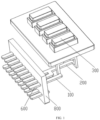
- a plug-in apparatus includes an wire inlet connection portion 100 and a wire outlet connection portion 200, a fuse 300 is connected between a first end of the wire inlet connection portion 100 and a first end of the wire outlet connection portion 200, a second end of the wire inlet connection portion 100 is connected to a power supply wire 400, and a second end of the wire outlet connection portion 200 is connected to a load wire 500; and the second end of the wire outlet connection portion 200 has at least one connection branch 202, each of which is used as a load interface, and a load may be connected to the connection branch 202 through the load wire 500.
- the fuse 300 is connected between the wire inlet connection portion 100 and the wire outlet connection portion 200, the power supply wire 400 is connected to the wire inlet connection portion 100, and the load is connected to the connection branch 202 of the wire outlet connection portion 200 through the load wire 500, so as to realize the power supply to the load; the plurality of connection branches 202 shunt current to supply power to a plurality of loads, so that a wire diameter of the load wire 500 can be reduced; the fuse 300 protects the load wire 500 connected to the connection branch 202, so that a protected wire diameter reduction is realized and the safety is guaranteed; further, a plurality of loads share one fuse, which saves the number of the fuses 300 and increases the convenience of wiring.
- the wire diameter of a wire is usually proportional to the rated current, i.e., as the wire diameter increases, the rated current increases, and the carried current increases.
- the required specification of the fuse 300 is calculated based on the specification of the load to select an appropriate fuse 300, and then the load wire 500 with an appropriate wire diameter is matched based on the selected fuse 300, so that the load, the fuse 300 and the load wire 500 are matched with each other, thereby preventing the waste caused by using the load wire 500 with a large wire diameter for small current, and avoiding the fact that the wire diameter of the load wire 500 is too small such that the load wire 500 is overheated and cut while the fuse 300 does not respond, so as to eliminate potential safety hazards.
- a wire diameter of the wire outlet connection portion 200 is also determined, and a wire diameter of the wire inlet connection portion 100 is designed according to the magnitude of the current inlet.
- the wire outlet connection portion 200 may be made of one or more materials such as copper, aluminum, magnesium and beryllium, or other conventional metals or alloys, and may be fabricated into a sheet or column shape, may be extendable along a straight line or represent a right-angle shape, and bifurcate into a plurality of parallel connection branches 202 at the second end.
- the wire inlet connection portion 100 may also be made of one or more materials such as copper, aluminum, magnesium and beryllium, or other conventional metals or alloys.
- the shape of the wire inlet connection portion 100 is similar to that of the wire outlet connection portion 200 except for the bifurcation at the second end.
- the design principle is to facilitate the connection of wires, including the power supply wire 400 and the load wire 500, and to facilitate the connection of the fuse 300.
- the fuse 300 When there are two or more connection branches 202 connected to the load wires 500, the fuse 300 is adapted to a load with the smallest rated current among the loads to which the load wire 500 is connected.
- the required specification of the fuse 300 is calculated by the rated current of the load to which the load wire 500 is to be connected.
- connection branches 202 When there are a plurality of connection branches 202, i.e., a plurality of loads are to be connected, the fuse is matched according to the load with the smallest rated current among the loads to be connected, i.e., the calculated minimum specification of the fuse 300 is taken as the actually selected specification of the fuse 300, and then the load wire 500 with an appropriate wire diameter is matched based on the specification of the fuse 300, thereby protecting the load wire 500 with the smallest wire diameter, and then protecting all of the load wires 500.
- the calculation method and the matching method are the prior arts, which will not be repeated here.
- the wire diameter of the load wire 500 can be smaller than that of the power supply wire 400, thereby achieving the purpose of wire diameter reduction.
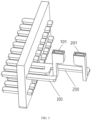
- the plug-in apparatus further includes at least one connection terminal 600, which is connected to the second end of the wire inlet connection portion 100 and at least one connection branch 202.
- the connection terminal 600 is connected to an external wire, such as the power supply wire 400 or the load wire 500.
- the wire diameter of the connection terminal 600 connected to the connection branch 202 i.e., the connection terminal 600 downstream of the fuse 300, is determined by the specification of the fuse 300, and for the detail, please refer to the way of determining the wire diameter of the load wire 500.
- the wire diameter of the connection terminal 600 connected to the wire inlet connection portion 100 i.e., the connection terminal 600 upstream of the fuse 300, is determined by the current inlet.
- connection terminal 600 may be designed as a universal type according to the upstream and downstream conditions, which is convenient for actual wiring and improves the flexibility of use.
- the number of the connection terminals 600 may be the same as a sum of the number of the wire inlet connection portions 100 and a total number of the connection branches 202, or it may be greater than the sum for backup for other connection wirings.
- the connection terminal 600 may be made of one or more materials of copper, aluminum and magnesium, or other conventional metals or alloys.
- the plug-in apparatus further includes a plug-in portion 700 provided with at least one plug-in through-hole 701 penetrating from a first end to a second end thereof, one end of the connection terminal 600 is connected to the second end of the wire inlet connection portion 100 or the connection branch 202, the other end of the connection terminal 600 extends into the plug-in through-hole 701 from one end of the plug-in through-hole 701, and the other end of the plug-in through-hole 701 is connected to an external wire, specifically for fixing the power supply wire 400 or the load wire 500, so that the power supply wire 400 is connected to the second end of the wire inlet connection portion 100 and the load wire 500 is connected to the connection branch 202.
- a plug-in portion 700 provided with at least one plug-in through-hole 701 penetrating from a first end to a second end thereof, one end of the connection terminal 600 is connected to the second end of the wire inlet connection portion 100 or the connection branch 202, the other end of the connection terminal 600 extends into the plug-
- connection between the connection terminal 600 and the second end of the wire inlet connection portion 100 and the connection between the connection terminal 600 and the connection branch 202 may be both achieved by welding, and the connection between a crimped terminal wire and the power supply wire 400 or the load wire 500 may be achieved by crimping.
- the load wire 500 extends into the plug-in through-hole 701, and the connection terminal 600 crimps the load wire 500 in the plug-in through-hole 701 to realize the connection, which can reduce the external welding spots and increase the convenience of wiring compared with welding.
- connection terminals 600 may be disposed in parallel with each other, and correspondingly, all of the plug-in through-holes 701 are also disposed in parallel with each other, with the distribution as the connection terminals 600.
- the connection terminals 600 are plugged into the plug-in through-holes 701 in a one-to-one correspondence.
- connection terminals 600 Regarding the specific arrangement of the connection terminals 600, the following two forms are taken as examples:
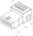
- the positioning plate 800, the wire inlet connection portion 100 and the wire outlet connection portion 200 are all disposed in the housing 900, the plug-in portion 700 is detachably connected to the housing 900 from one side of the housing 900, and the first end of the plug-in portion 700 is located in the housing 900.
- the positioning plate 800 is disposed in the housing 900, so that all of the connection terminals 600 are located in the housing 900, and the positioning plate 800 is configured to snap in the housing 900.
- the first end of the plug-in portion 700 is plugged into the housing 900 from one side of the housing 900 to realize a detachable connection, which specifically may be a snap connection.
- sockets are provided on a top of the housing 900 at positions corresponding to the first end of the wire inlet connection portion 100 and the first end of the wire outlet connection portion 200, and the sockets are configured to fix the fuse 300.
- the first end of the wire inlet connection portion 100 is provided with a first connector 101
- the first end of the wire outlet connection portion 200 is provided with a second connector 201
- the first connector 101 and the second connector 201 are connected to the fuses 300.
- Each of the first connector 101, the second connector 201 and the connection branch 202 may be made of one or more materials of copper, aluminum, magnesium and beryllium, or other conventional metals or alloys.
- the socket is located at the top of the housing 900, and the fuse 300 is connected to the wire inlet connection portion 100 and the wire outlet connection portion 200 located inside the housing 900 through the socket.
- the conventional MINI fuse with the rated current of 10A, 15A, 20A, 25A, 30A, etc.
- pins of the fuse 300 extend into the housing 900 through the socket and are connected to the wire inlet connection portion 100 and the wire outlet connection portion 200.
- one end of the wire inlet connection portion 100 is provided with the first connector 101
- one end of the wire outlet connection portion 200 is provided with the second connector 201.
- the first connector 101 and the second connector 201 may be annular and matched with pins of the fuse 300, to realize the connection with the fuse 300 and facilitate the assembly of the fuse 300.
- the socket has a shape matched with that of the fuse 300, and has a function of fixing the fuse 300 after the fuse 300 is connected to the wire inlet connection portion 100 and the wire outlet connection portion 200.
- the socket may be formed by removing a material from the top of the housing 900, or integrally formed with the housing 900, or formed on a plug-in board 901, and then the plug-in board 901 is connected to the top of the housing 900.
- the top of the housing 900 has an opening for mounting the plug-in board 901, and the plug-in board 901 is detachably connected into the opening.
- an outer wall of the housing 900 is provided with at least one positioning hanger 902.
- two positioning hangers 902 are located at two sides of the housing 900, respectively.
- the housing 900 is connected to other elements, e.g., assembled on the vehicle body, through the positioning hangers 902, and the specific structure is determined by the connected position and elements, which may be a slot structure or any other structural form.
- both sides of the housing 900 may be provided with the positioning hangers 902, and further, the positioning hangers 902 on both sides of the housing 900 are symmetrically disposed.
- the plug-in portion 700 is connected to one end of the housing 900, such as a front end of the housing 900, the fuse 300 is connected from the top of the housing 900, and the positioning hangers 902 are located at left and right sides of the housing 900, so that the whole apparatus is convenient for assembling.
- the fuse 300 is assembled outside the housing 900 to facilitate the heat dissipation of the fuse 300.
- the wire inlet connection portion 100 and the wire outlet connection portion 200 are disposed in at least one pair, and the position between the wire inlet connection portions 100 and the wire outlet connection portions 200 of each pair is connected to the fuse 300.
- Each pair of the wire inlet connection portions 100 and the wire outlet connection portions 200 may be called as a wiring module, and a plurality of wiring modules are located in the housing 900. Loads of the same type may be connected to one wiring module, e.g., a plurality of lamps are connected to one wiring module, a plurality of horns are connected to one wiring module, etc.
- Loads of similar specifications may also be connected to one wiring module, e.g., lamps and horns with the rated current of 10A are all connected to one wiring module, so that the fuse 300 matched with a single wiring module is more suitable, thereby achieving a protective function without causing waste.
- the number of the wiring modules and the number of shunt circuits of each wiring module may be determined according to the specific type, specification and number of the loads in conjunction with the electrical principle requirements of the whole vehicle, so as to flexibly set the on-load form, as illustrated in FIG. 4 , which may be four-way on-load, i.e., four-way fuses, thereby greatly expanding the capacity of a central power distribution box.
- the intervals between the adj acent wiring modules may be the same, and equal intervals between the connectors of the adjacent wiring modules enables equal intervals between the matched fuses 300, and the sockets on the plug-in board 901 are equally spaced, so that the structure is regular and the use is convenient.
- Each of the plug-in portion 700, the positioning plate 800, the housing 900 and the plug-in plate 901 is made of an insulating material, such as one or more of as amide, polycarbonate, polyvinyl chloride, polyurethane, polysulfone, polytetrafluoroethylene, polyethylene, polypropylene, polyphenylene ether, polyester, plastic (PPS, DAP, PBT, ABS), phenolic resin, urea formaldehyde, nylon, rubber (TPE, PFE, TPR, EVA), foam (XPE), crosslinked polyethylene (XLPE), ethylene tetrafluoroethylene (ETFE), perfluoroalkoxy alkane, styrene-acrylonitrile copolymer, polymethacrylate, polyphenylene sulfide, polystyrene, polyoxymethylene resin.
- an insulating material such as one or more of as amide, polycarbonate, polyvinyl chloride, polyurethane, poly
- At least part of surfaces of the wire inlet connection portion and the wire outlet connection portion are provided with plating layers. Since the surfaces of the wire inlet connection portion and the wire outlet connection portion may be exposed to air and water, and even the air in some places contains salt, those surfaces will be subject to oxidation and salt mist corrosion, thereby damaging the service life of the apparatus. Therefore, the surfaces of the wire inlet connection portion and the wire outlet connection portion are provided with plating layers, which can effectively prevent the corrosion of air, water and salt mist, prolong the service life of the apparatus and reduce the occurrence of safety accidents.
- a material of the plating layer may be one or alloy or combinations of nickel, cadmium, zirconium, chromium, cobalt, manganese, aluminum, tin, titanium, zinc, copper, silver, gold, graphene and carbon-based compound.
- Table 1 Material of the plating layer No plating layer Nickel Cadmium Zirconium Chromium Cobalt Manganese Aluminum Tin Titanium Zinc Copper Silver Gold Graphene Carbonnano Service life of the plug-in apparatus under the salt mist spraying condition (H) 1936 3756 3762 3698 3526 3463 3777 3454 3567 3845 3589 3752 3869 3956 3924 4257
- a thickness of a plating layer in an area for connecting the fuse on each of the wire inlet connection portion and the wire outlet connection portion is greater than or equal to that of a plating layer outside the area, so as to particularly protect the area for connecting the fuse.
- the conductive property (conductivity) of the plating layer in the area for connecting the fuse on each of the wire inlet connection portion and the wire outlet connection portion is better than that of the plating layer outside the area.
- silver is plated in the area for connecting the fuse, and tin is plated in other areas.
- gold is plated in the area for connecting the fuse, and zinc is plated in other areas.
- the plug-in apparatus in which the conductive property of the plating layer in the area for connecting the fuse is equal to that of the plating layer outside the area
- the plug-in apparatus in which the conductive property of the plating layer in the area for connecting the fuse is better than that of the plating layer outside the areahas a longer service life.
- the thickness of the surface plating layer of each of the wire inlet connection portion and the wire outlet connection portion is 0.09 to 1,500 ⁇ m.
- a nickel plating layer is adopted to investigate the service life of the plug-in apparatus under the salt mist spraying condition, and the results are shown below in Table 3: Table 3 Plating layers with different thicknesses ( ⁇ m) 0.001 0.003 0.006 0.009 0.01 0.03 0.03 0.03 0.1 0.3 0.6 0.3 1 13 1 1 5 10 Service life of the plug-in apparatus under the salt mist spraying condition (H) 2036 2124 2264 2326 2474 2684 2841 3284 3342 2326 3422 3468 3527 3549 3642 3676 3706 3728 Contact voltage drop (mv) 0.1 0.3 0.3 0.3 0.1 0.3 0.1 53 53 50 as as 43 40 Electrical failure rate of the whole vehicle (0.01%) 0.1
- the thickness of the plating layer is less than 0.09 ⁇ m, the service life of the plug-in apparatus cannot meet the basic condition of more than 3,000 H.
- the thickness of the plating layer is greater than 1,500 ⁇ m, the service life of the plug-in apparatus still cannot meet the basic condition of more than 3,000 H, and in order to obtain the plating layer with the thickness greater than 1,500 ⁇ m, the material consumption and the processing time increase greatly. Therefore, the thickness of the surface plating layer of each of the wire inlet connection portion and the wire outlet connection portion is selected to be 0.09 to 1,500 ⁇ m. Within the thickness range of the plating layer, the contact voltage drop and the electrical failure rate of the whole vehicle meet the requirements of use.
- the fuse may be one or more of a hot-melt fuse, a thermistor fuse, a Positive Temperature Coefficient (PTC) resistor fuse, a memory alloy fuse, a thermal trigger electronic fuse (in the form of sensor, controller or power tube) and a current trigger electronic fuse (in the form of sensor, controller or power tube).
- the rated current of the fuse covers 0.5 to 3,000 A, and the cross-sectional area may be selected as 0.1 to 30 mm 2 .
- a current carrying capacity of the power supply wire connected to the second end of the wire inlet connection portion is greater than or equal to that of the load wire connected to the second end of the wire outlet connection portion, which is beneficial to achieve the purpose of wire diameter reduction and current-shunting of the wire.
- the wire diameter of the power supply wire may be 0.35 to 50 mm 2
- the wire diameter of the load wire may be 0.13 to 35 mm 2 .
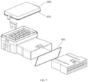
- the socket is connected to a cover 905, and at least one first sealing member 903 sleeves on the cover, and the sealing member 903 is located between the cover 905 and the housing 900; a second sealing member 904 sleeves on the first end of the plug-in portion 700, and the second sealing member 904 is located between the plug-in portion 700 and the housing 900.
- the cover 905 may be detachably or integrally connected to the socket. For example, after being connected to the socket, the cover 905 is fixed by an injection process, so that the cover 905 and the housing 900 are integrally formed.
Landscapes
- Engineering & Computer Science (AREA)
- Mechanical Engineering (AREA)
- Fuses (AREA)
- Details Of Connecting Devices For Male And Female Coupling (AREA)
Applications Claiming Priority (2)
| Application Number | Priority Date | Filing Date | Title |
|---|---|---|---|
| CN202011522737.1A CN112582240B (zh) | 2020-12-21 | 2020-12-21 | 插接装置 |
| PCT/CN2021/124844 WO2022134788A1 (zh) | 2020-12-21 | 2021-10-20 | 插接装置 |
Publications (2)
| Publication Number | Publication Date |
|---|---|
| EP4266344A1 true EP4266344A1 (de) | 2023-10-25 |
| EP4266344A4 EP4266344A4 (de) | 2024-07-10 |
Family
ID=75136527
Family Applications (1)
| Application Number | Title | Priority Date | Filing Date |
|---|---|---|---|
| EP21908789.7A Pending EP4266344A4 (de) | 2020-12-21 | 2021-10-20 | Steckvorrichtung |
Country Status (5)
| Country | Link |
|---|---|
| US (1) | US20240039219A1 (de) |
| EP (1) | EP4266344A4 (de) |
| CN (1) | CN112582240B (de) |
| MX (1) | MX2023007439A (de) |
| WO (1) | WO2022134788A1 (de) |
Families Citing this family (4)
| Publication number | Priority date | Publication date | Assignee | Title |
|---|---|---|---|---|
| CN112582240B (zh) * | 2020-12-21 | 2026-01-13 | 长春捷翼汽车科技股份有限公司 | 插接装置 |
| CN114421242A (zh) * | 2022-01-24 | 2022-04-29 | 东莞市源创电子科技有限公司 | 一种连接器、数据线及电子设备 |
| DE102022124801A1 (de) * | 2022-09-27 | 2024-03-28 | Fep Fahrzeugelektrik Pirna Gmbh & Co. Kg | Modulare elektronische Sicherungen und Sicherungsbox |
| CN120319643B (zh) * | 2025-06-17 | 2025-11-07 | 浙江众志汽车电器有限公司 | 一种保险盒 |
Family Cites Families (16)
| Publication number | Priority date | Publication date | Assignee | Title |
|---|---|---|---|---|
| US6878004B2 (en) * | 2002-03-04 | 2005-04-12 | Littelfuse, Inc. | Multi-element fuse array |
| JP2003272511A (ja) * | 2002-03-20 | 2003-09-26 | Toshiba Syst Technol Corp | ヒューズホルダー |
| CN2615936Y (zh) * | 2003-03-04 | 2004-05-12 | 郑文宗 | 具有保险丝的电源分线座 |
| JP5636865B2 (ja) * | 2010-10-19 | 2014-12-10 | 株式会社豊田自動織機 | 電源ユニットおよび電源 |
| CN201868743U (zh) * | 2010-11-25 | 2011-06-15 | 中国移动通信集团设计院有限公司 | 一种直流插接箱 |
| JP5806012B2 (ja) * | 2011-06-28 | 2015-11-10 | 矢崎総業株式会社 | ヒューズブロック及びそれを備えた電気接続箱 |
| CN203084465U (zh) * | 2013-02-05 | 2013-07-24 | 中联重科股份有限公司 | 电源控制系统和工程机械车辆 |
| CN204258206U (zh) * | 2014-11-26 | 2015-04-08 | 浙江吉利汽车研究院有限公司 | 一种电动车用分线盒 |
| CN105914111A (zh) * | 2016-05-04 | 2016-08-31 | 湖南中普防雷股份有限公司 | 一种配电箱熔断器与接线端子安装方法及装置 |
| CN106711885A (zh) * | 2016-12-28 | 2017-05-24 | 重庆长安汽车股份有限公司 | 汽车线束分线盒 |
| CN207241627U (zh) * | 2017-08-31 | 2018-04-17 | 中国第一汽车股份有限公司 | 一种商用车用底盘熔断器盒 |
| CN207458878U (zh) * | 2017-10-24 | 2018-06-05 | 中国第一汽车股份有限公司 | 一种汽车用蓄电池正极保险丝盒 |
| CN208299379U (zh) * | 2018-05-25 | 2018-12-28 | 北京比亚迪模具有限公司 | 一种分线盒及车辆 |
| CN210925937U (zh) * | 2019-11-12 | 2020-07-03 | 安徽合力股份有限公司 | 一种保险丝盒 |
| CN112582240B (zh) * | 2020-12-21 | 2026-01-13 | 长春捷翼汽车科技股份有限公司 | 插接装置 |
| CN214254330U (zh) * | 2020-12-21 | 2021-09-21 | 长春捷翼汽车零部件有限公司 | 插接装置 |
-
2020
- 2020-12-21 CN CN202011522737.1A patent/CN112582240B/zh active Active
-
2021
- 2021-10-20 US US18/265,944 patent/US20240039219A1/en active Pending
- 2021-10-20 EP EP21908789.7A patent/EP4266344A4/de active Pending
- 2021-10-20 WO PCT/CN2021/124844 patent/WO2022134788A1/zh not_active Ceased
- 2021-10-20 MX MX2023007439A patent/MX2023007439A/es unknown
Also Published As
| Publication number | Publication date |
|---|---|
| CN112582240A (zh) | 2021-03-30 |
| WO2022134788A1 (zh) | 2022-06-30 |
| EP4266344A4 (de) | 2024-07-10 |
| MX2023007439A (es) | 2023-07-03 |
| CN112582240B (zh) | 2026-01-13 |
| US20240039219A1 (en) | 2024-02-01 |
Similar Documents
| Publication | Publication Date | Title |
|---|---|---|
| EP4266344A1 (de) | Steckvorrichtung | |
| US11699835B2 (en) | Circuit board and battery connection module | |
| CN101809785B (zh) | 蓄电池组件 | |
| TWI482191B (zh) | 用於匯流及非匯流之電力連接之通用雙螺栓模組保險絲座總成 | |
| JP3990960B2 (ja) | バッテリ接続プレートおよびその取付構造 | |
| US6461172B2 (en) | Multiple function high current interconnect with integrated bus bar | |
| EP2306582B1 (de) | Zelltemperaturfühlvorrichtung für ein Batteriemodul | |
| CN110989787A (zh) | 液冷服务器 | |
| TW202005144A (zh) | 具有彈簧接觸元件之用於儲存電能的電池單體的機構 | |
| CN108141014B (zh) | 密封的模块化配电装置 | |
| JP6581958B2 (ja) | 電圧検出構造および電圧検出モジュール | |
| EP3780918A1 (de) | Fpc-verbindungsstruktur und verfahren zum verbinden mit einer leiterplatte unter verwendung derselben | |
| JP2022160375A (ja) | バッテリ接続モジュール | |
| US10276337B2 (en) | Fuses with integrated metals | |
| CN220821948U (zh) | 电力传输件、电连接组件和充电座 | |
| US9660246B2 (en) | Battery terminal | |
| CN214254330U (zh) | 插接装置 | |
| US8882309B2 (en) | Device for fastening and contacting a lighting means, a lighting module, or lamp | |
| US20170125923A1 (en) | Ground bracket for an outlet of a rack power distribution unit and related method | |
| KR19980038177A (ko) | 전지팩의 서미스터 장착방법 | |
| US6154118A (en) | Circuit protective device with positive temperature coefficient element and electric junction box with the device | |
| EP4435433A1 (de) | Sammelschienenanordnung zur messung eines elektrischen stroms zwischen zwei sammelschienen | |
| KR102837171B1 (ko) | 전류 검출 장치 | |
| CN221747496U (zh) | 一种大功率接线端子结构 | |
| US10763629B1 (en) | Integrated assembly of an electrical conductor, a fuse and a connector |
Legal Events
| Date | Code | Title | Description |
|---|---|---|---|
| STAA | Information on the status of an ep patent application or granted ep patent |
Free format text: STATUS: THE INTERNATIONAL PUBLICATION HAS BEEN MADE |
|
| PUAI | Public reference made under article 153(3) epc to a published international application that has entered the european phase |
Free format text: ORIGINAL CODE: 0009012 |
|
| STAA | Information on the status of an ep patent application or granted ep patent |
Free format text: STATUS: REQUEST FOR EXAMINATION WAS MADE |
|
| 17P | Request for examination filed |
Effective date: 20230615 |
|
| AK | Designated contracting states |
Kind code of ref document: A1 Designated state(s): AL AT BE BG CH CY CZ DE DK EE ES FI FR GB GR HR HU IE IS IT LI LT LU LV MC MK MT NL NO PL PT RO RS SE SI SK SM TR |
|
| P01 | Opt-out of the competence of the unified patent court (upc) registered |
Effective date: 20231228 |
|
| DAV | Request for validation of the european patent (deleted) | ||
| DAX | Request for extension of the european patent (deleted) | ||
| A4 | Supplementary search report drawn up and despatched |
Effective date: 20240606 |
|
| RIC1 | Information provided on ipc code assigned before grant |
Ipc: H01R 13/684 20110101ALN20240531BHEP Ipc: H01R 43/16 20060101ALN20240531BHEP Ipc: H01R 13/03 20060101ALN20240531BHEP Ipc: B60R 16/023 20060101ALI20240531BHEP Ipc: H01H 85/20 20060101AFI20240531BHEP |
|
| STAA | Information on the status of an ep patent application or granted ep patent |
Free format text: STATUS: EXAMINATION IS IN PROGRESS |
|
| 17Q | First examination report despatched |
Effective date: 20250213 |