EP4266330A1 - Dispositif et système de formation de faisceau de fils, en particulier un faisceau de fils - Google Patents
Dispositif et système de formation de faisceau de fils, en particulier un faisceau de fils Download PDFInfo
- Publication number
- EP4266330A1 EP4266330A1 EP23167517.4A EP23167517A EP4266330A1 EP 4266330 A1 EP4266330 A1 EP 4266330A1 EP 23167517 A EP23167517 A EP 23167517A EP 4266330 A1 EP4266330 A1 EP 4266330A1
- Authority
- EP
- European Patent Office
- Prior art keywords
- bundling
- strand
- unit
- area
- strip
- Prior art date
- Legal status (The legal status is an assumption and is not a legal conclusion. Google has not performed a legal analysis and makes no representation as to the accuracy of the status listed.)
- Pending
Links
Images


Classifications
-
- H—ELECTRICITY
- H01—ELECTRIC ELEMENTS
- H01B—CABLES; CONDUCTORS; INSULATORS; SELECTION OF MATERIALS FOR THEIR CONDUCTIVE, INSULATING OR DIELECTRIC PROPERTIES
- H01B13/00—Apparatus or processes specially adapted for manufacturing conductors or cables
- H01B13/012—Apparatus or processes specially adapted for manufacturing conductors or cables for manufacturing wire harnesses
- H01B13/01263—Tying, wrapping, binding, lacing, strapping or sheathing harnesses
- H01B13/01281—Harness wrapping apparatus
-
- H—ELECTRICITY
- H01—ELECTRIC ELEMENTS
- H01B—CABLES; CONDUCTORS; INSULATORS; SELECTION OF MATERIALS FOR THEIR CONDUCTIVE, INSULATING OR DIELECTRIC PROPERTIES
- H01B13/00—Apparatus or processes specially adapted for manufacturing conductors or cables
- H01B13/012—Apparatus or processes specially adapted for manufacturing conductors or cables for manufacturing wire harnesses
- H01B13/01263—Tying, wrapping, binding, lacing, strapping or sheathing harnesses
Definitions
- the present invention relates to a strand bundling device, by means of which a bundling strip can be placed in a bay shape on and around a linear strand, whereby the strand, in particular a cable harness or a cable harness structure with several branching individual strands ("cable harness"), is bundled.
- the invention relates to a system which has such a strand bundling device or more such strand bundling devices.
- Bundling a strand and applying a bundling strip around the strand to keep the strand bundled is difficult to automate in the prior art.
- the assembly of additional elements on the strand and the assembly of the strand, for example in a motor vehicle bodyshell, is also a challenge for automation technology.
- the prior art uses a wrapping tape to bundle strands or cable harnesses.
- the additional elements are currently also attached to the strand with this wrapping tape. These additional elements are used when assembling the strand in the vehicle in order to attach it to/in the vehicle bodyshell.
- the invention proposes a strand bundling device which has a strand bundling unit (A) or more such strand bundling units.
- the strand bundling device in particular its strand bundling unit, is set up (i.e. designed and arranged) to lay a bundling strip, in particular bundling adhesive strip, in a bay shape on and around a linear strand and thereby bundle the strand or to combine the strand into a fixed bundle.
- a system for bundling the strand is proposed, the system having one or more such strand bundling devices.
- a method for bundling a strand using such a strand bundling device and/or using such a system is disclosed.
- the strand can have a main strand and one or more secondary strands branching off from it, with one or more further secondary strands branching off from the secondary strands, etc.
- the strand is in particular a wiring harness for a motor vehicle.
- the strand can be formed from a large number of individual strands arranged in parallel; Here, a cable that is formed from several individual cables is understood to mean a strand.
- the strand bundling device By means of the strand bundling device, in particular by means of its strand bundling unit, the strand is arranged parallel to a width direction (y) of the strand bundling unit and is moved relative to the strand bundling unit only along a straight bundling direction arranged parallel to a longitudinal direction (x) of the strand bundling unit through a bundling region of the strand bundling unit.
- the strand enters the strand bundling unit along the bundling direction - in particular in the bundling direction.
- the strand bundled by means of the bundling strip also emerges from the strand bundling unit along the bundling direction.
- the strand In order to be bundled by means of the bundling strip, the strand enters the strand bundling unit in or against the bundling direction, but in any case parallel to it, and exits the strand bundling unit in or against the bundling direction, but in any case parallel to it - a movement of the Strand along its longitudinal direction is completely omitted.
- the strand is moved relative to the strand bundling unit, for example by keeping the strand stationary and moving the strand bundling device towards or away from the stationary strand. Furthermore, it is conceivable that the strand is moved relative to the strand bundling unit by the strand bundling device being stationary and the strand being moved towards or from the stationary strand bundling device. Furthermore, the strand and the strand bundling device can both be moved and thereby moved towards or away from one another.
- the strand bundling unit has a carrier device, for example a carrier plate, and a bundling strip dispenser, which is designed to provide the bundling strip in the bundling area.
- the strand bundling unit includes a feeder device arranged on the carrier device and at least partially or partially in the bundling area.
- the application device engages in the bundling area and is set up to take over the bundling strip from the bundling strip dispenser and place it in a bay shape around and on the strand by moving the strand along the bundling direction relative to the application device and thereby through the bundling area.
- the bundling strip is the bundling adhesive strip (for example sections of an adhesive tape provided on a roll, etc.)
- the bundling strip is preferably applied in such a way that one adhesive side of the bundling adhesive strip faces the strand, so that the adhesive sides of the protruding flags face each other and are glued together while moving the strand relative to the strand bundling device as part of the bundling process, that is to say automatically.
- the strand bundling device In order to arrange the strand bundling device and the strand independently of each other again after bundling the strand or after the bay-shaped application of the bundling strip around and on the strand, so that the strand bundling device and the strand can be moved freely in space completely independently of one another, the strand bundling device is moved and/or the strand along the longitudinal direction (v) of the strand is not required.
- This is advantageous in that it makes it possible to have a strand which has end elements at both ends (foot side of the width direction and tip side of the width direction of the strand bundling device) which prevent the strand bundling device from being removed from the strand along its longitudinal extension direction (v).
- these end elements are in particular electrical coupling elements, such as plugs, sockets, etc., and/or branching or branching points at which another strand branches off from the bundled strand. Therefore, when the strand bundling device is used as intended, in particular in the method for bundling the strand by means of the strand bundling device and/or the system having the strand bundling device, provision is made according to the invention for moving the strand to bundle it and for subsequent independent movement along the strand bundling device the width direction (y), i.e. along the longitudinal direction (v) of the strand is completely omitted.
- the strand bundling device includes in particular a cutting unit for cutting off the bundling strip or bundling adhesive strip.
- the strand bundling device can also be designed without such a cutting unit, in which case it is provided that the bundling strip is already cut off or provided in sections.
- a further possible embodiment of the strand bundling device provides that the strand bundling unit has a counter-holder element and a lock mechanism having an entry lock element and an exit lock element, by means of which the counter-holder element and the carrier device are spaced apart from one another over a lead-through distance and fastened to one another.
- the bundling area is formed between the carrier device and the counter-holder element.
- the lock mechanism is adjustable between an entry position and an exit position.
- the lock mechanism has an electrical, pneumatic and/or hydraulic actuator for each lock element, so that the lock mechanism can be adjusted electrically, pneumatically and/or hydraulically between the entry position and the exit position.
- the entry lock element and the counter-holder element are decoupled from one another by moving the entry lock element into its decoupling position, in which a first force and/or positive connection that can be mediated between the carrier device and the counter-holder element by means of the entry lock element is open.
- a first force and/or positive connection that can be mediated between the carrier device and the counter-holder element by means of the entry lock element is open.
- the counter-holder element and the carrier device are releasably and non-destructively reversibly fastened to one another by means of the exit lock element by adjusting the exit lock element into its coupling position, in which the exit lock element provides a different, second force and/or positive connection between the carrier device and the counter-holder element.
- the exit lock element and the counter-holder element are decoupled from one another by moving the exit lock element into its decoupling position, in which the second force and/or positive connection, which can be mediated between the carrier device and the counter-holder element by means of the exit lock element, is open.
- the counter-holder element and the carrier device are non-destructively reversibly and releasably attached to one another by means of the entry lock element by adjusting the entry lock element into its coupling position, in which the entry lock element mediates the first force and/or positive connection between the carrier device and the counter-holder element.
- the counter-holder element advantageously guides the strand along the bundling direction, so that undesirable deflection of the strand is particularly reliably prevented.
- a bundling strip remains stuck to the counter-holder element for a subsequent bundling process, so that the strand is brought into contact with the bundling strip particularly reliably.
- the counter-holder element is in particular designed to be straight and arranged parallel to the bundling direction. It can, for example, be designed as a counter-holder plate.
- the respective lock element has a corresponding connecting element of the connecting device.
- the respective lock element has, for example, a first bayonet connecting element, a first threaded connecting element, a first magnetic connecting element and/or a first hook connecting element.
- the carrier device or the counter-holder element - depending on whether the lock element is attached or fixed to the carrier device or on the counter-holder element - has an associated, corresponding connecting element of the connecting device, which means that the carrier device or the counter-holder element has, for example, a second bayonet connecting element second threaded connecting element, a second magnetic connecting element and/or a second hook connecting element.
- the corresponding one of the first connecting elements and the corresponding corresponding one of the second connecting elements correspond to one another to form the connecting device.
- the strand bundling unit has a movement support device attached to the carrier device, which is designed to push and/or pull the strand into the bundling area along the bundling direction.
- the movement support device can, for example, have a movement support lever pivotably mounted on the carrier device or on the counter-holder element (if present), which can be driven by means of a pivot actuator in order to push or pull the strand along the bundling direction into the bundling area by means of the driven pivoting of the movement support lever.
- the movement support device can have a linearly movable movement support element, such as a slider, a hook, etc., which can be driven by means of a linear actuator.
- the strand can be pushed or pulled into the bundling area along the bundling direction.
- the strand can be additionally driven in the bundling direction for bundling it, which results in a particularly efficient movement of the strand through the bundling area.
- the strand bundling unit has an additional element dispenser which is designed to provide or supply an additional element to the strand in the bundling area.
- the additional element dispenser by means of the additional element dispenser, the additional element is placed on the strand that has not yet been bundled, or the additional element dispenser drops the additional element onto the strand that has not yet been bundled.
- the bundling strip is placed in a bay shape around the strand with the additional element.
- the additional element is fixed to the strand by means of the bundling strip.
- the production of the strand, in particular the cable harness is even more efficient. That which is tied to the strand or bundled with the strand
- Additional element can be designed, for example, as a fastening element, by means of which the strand, in particular the cable harness or cable harness, can be fixed in the intended installation position on a corresponding fastening element of a structural element, for example a motor vehicle bodyshell, that is, secured against unwanted movement.
- the additional element is designed as a vibration protection element.
- the wiring harness in the motor vehicle that is finished or ready for use in the intended installation position does not rest directly on the strand itself, but rather via the vibration protection element on the structural element, that is, for example, on the motor vehicle bodyshell.
- the vibration protection element on the structural element, that is, for example, on the motor vehicle bodyshell.
- the correspondingly manufactured wiring harness contributes to a particularly high NVH quality (NVH: noise, vibrations, harshness).
- the additional element can be designed as a protective or reinforcing element, by means of which the strand is protected particularly efficiently against mechanical influence at the corresponding point. Undesirable chafing of the cable harness or strand is prevented by means of the protective or reinforcing element.
- the strand bundling device has a further strand bundling unit (B), the strand bundling units (A, B) being fixed relative to one another along the width direction.
- the width directions of the strand bundling units therefore coincide to form a common width direction.
- the strand bundling units are fixed relative to one another along the width direction in such a way that the strand, while moving relative to the respective strand bundling unit, simultaneously enters the two strand bundling units and simultaneously exits the strand bundling units.
- the strand bundling device is advantageously set up to simultaneously place two bundling strips arranged next to one another along the longitudinal extension direction (v) of the strand in a bay shape around the strand by means of a single movement of the strand in the bundling direction.
- Additional strand bundling units (B) can be provided along the width direction.
- the strand bundling device has the additional element dispenser, in a further possible embodiment this is arranged between the two parallel strand bundling units (A, B), whereby the strand bundling device is set up to fix the additional element to the strand by means of the two bundling strips the strand is moved through the bundling areas. This enables a particularly reliable connection between the strand and the additional element.
- the strand bundling device - as provided in a possible further development - has a further strand bundling unit (C), the strand bundling units (A, C) being arranged in series along the longitudinal direction and fixed relative to one another.
- the bundling direction of the strand bundling units therefore coincide to form a common bundling direction.
- the strand bundling units are fixed relative to one another along the bundling direction in such a way that when the strand emerges from the strand bundling unit in the bundling direction, the strand enters the serially arranged strand bundling unit in the bundling direction.
- the strand bundling device is set up to place a first bundling strip in a bay shape around the strand and a second bundling strip in a bay shape around the first bundling strip by means of a single movement of the strand in the bundling direction, which results in particularly reliable bundling of the strand.
- the strand bundling device - has a further strand bundling unit (D), the strand bundling units (A, D) are fixed opposite each other relative to one another.
- the longitudinal directions (x) and the vertical directions (z) of the strand bundling units are therefore arranged in opposite directions to one another, with the width directions (y) of the strand bundling units running in parallel in the same direction.
- the bundling directions are arranged in opposite directions and parallel to one another, so that in order to move the strand completely through both strand bundling units, the strand is first moved relative to the strand bundling unit along its bundling direction through the associated bundling area. Then the strand is moved in a translation direction to the opposite strand bundling unit, in particular moved to the foot of the bundling direction belonging to the opposite strand bundling unit. The strand bundling unit arranged oppositely is then moved through the associated bundling area along the bundling direction.
- the strand bundling device is thus advantageously set up to create a first bundling strip in the shape of a bay by means of a single movement of the strand through the two opposite strand bundling units Lay the strand and a second bundling strip in a cove shape around the first bundling strip. It has proven to be particularly advantageous that the strand is on the same side when entering the strand bundling device and when exiting the strand bundling device. In other words, the entry area of the strand bundling unit (A) and the exit area of the strand bundling units (D) are arranged on a common side of the strand bundling device.
- the strand bundling units (A, B, C, D) can each be designed the same or different from one another.
- the application device has a gear- or spline-like wheel (for a simple description, the wheel is assumed to be a gear), the ring of which protrudes into the bundling area and which is rotatably mounted about an axis of rotation arranged parallel to the width direction (y). is.
- the axis of rotation and the bundling direction are arranged perpendicular to one another.
- the gear is designed to take over the bundling strip from the bundling strip dispenser by means of a take-over tooth, such that a tooth gap between the take-over tooth and a subsequent tooth is spanned by the bundling strip.
- the gear is designed to be rotated about the axis of rotation by means of the strand when it is moved through the bundling area in the bundling direction.
- the strand engages in the tooth gap, whereby the bundling strip is pushed into the tooth gap by means of the strand and is placed in a bay shape around the strand while the gear rotates.
- a tooth gap surface gives the strand a rotational movement about its longitudinal extension direction (v) as the gear rotates, in that the strand and the tooth gap surface roll on one another.
- the rotational movement of the strand can be further increased by rolling the strand on the counter-holder element.
- a further possible embodiment of the strand bundling device provides that the application device has a locking mechanism, which in turn has two locking arches.
- the locking arches can be pivoted in mirror image to one another via their respective first ends on a common pivot axis and are mounted on the carrier device.
- the second ends of the locking arches are connected by means of a - in particular reversibly elastic or flexible - connecting band and are spaced apart from one another in a rest position of the locking mechanism.
- the docking device a transfer device which includes a transfer arm and a lever mechanism.
- the lever mechanism has a release lever and a gear lever, with the release lever and the takeover arm being connected to one another by means of the gear lever.
- the release lever is arranged in a feed area of the strand bundling unit or at least protrudes into the feed area.
- the release lever is deflected, whereby the bundling strip is placed over the second ends of the closing sheets and thereby over the connecting band by means of the take-over arm.
- the closing mechanism is further set up to place the bundling strip around the strand in a bay shape by bending the connecting band and the bundling strip above it in the middle in the direction of the pivot axis by means of the strand, which is further moved in the bundling direction into and through the bundling area.
- the second ends of the closing arches are moved towards each other, whereby the bundling strip is placed around the strand in a bay shape using the connecting band.
- the connecting band encloses the strand when it bends the connecting band and the second ends of the closing arches are moved towards each other.
- this configuration enables particularly efficient bundling of the strand.
- bundling that is, the - in particular adhesive - attachment of the bundling strip can be carried out without the use of an electrical, magnetic, pneumatic or hydraulic actuator.
- the strand bundling device has a robot coupling unit, which is arranged in particular on the carrier device or on the counter-holder element.
- the system according to the invention has a strand bundling device designed according to the above description or more such strand bundling devices, wherein the strand bundling device or one or more of the strand bundling devices is/are reversibly and non-destructively releasably attached to an auxiliary construction structure.
- the auxiliary construction structure can, for example, be the robot or have the robot.
- the auxiliary construction structure is a building board, or the auxiliary building structure has the building board.
- the strand bundling device or one or more of the strand bundling devices is attached to the building board (a so-called building board), the building board being configurable depending on the strand shape to be formed by attaching the strand bundling device to fastening points corresponding to the strand shape.
- the strand shape is defined or specified in particular by the end elements (electrical coupling elements, plugs, sockets, etc.) and/or by the branching or branching points at which another strand branches off from the strand to be bundled or produced.
- the system can be used in a particularly versatile or flexible manner if the attachment by means of which the strand bundling device(s) is/are attached to the building board is designed to be reversible and non-destructively detachable - in particular without tools.
- the system has a tensioning device which is set up to assemble and tension and/or keep tensioned on the strand in accordance with the strand shape to be formed (i.e. with the aid of the tensioning device).
- the strand is stretched or held stretched on the tensioning device.
- the building board has a cutout which corresponds in shape and geometry to the strand to be formed or bundled - i.e. with its designated strand shape.
- the strand bundling device is arranged at one edge of the cutout.
- the strand bundling device is arranged on the building board in such a way that the tip of the bundling direction is directed towards the building board.
- the clamping device with the strand stretched on it is arranged above the building board (foot side of the bundling direction).
- the strand bundling device is arranged on the building board in such a way that the bundling direction points away from the building board.
- the building board together with the strand bundling device attached to it is moved over the strand held on the clamping device. The strand passes through in the bundling direction through the cutout and is moved through the bundling area of the strand bundling device - also in (the same) bundling direction.
- the bundling strip is placed in a bay shape on and around the linear strand and is thereby bundled by arranging the strand parallel to the width direction (y) of the strand bundling unit and relative to the strand bundling unit only along a parallel to a longitudinal direction (x) of the strand bundling unit arranged straight bundling direction is moved through a bundling area of the strand bundling unit.
- the strand to be bundled enters the strand bundling unit along the bundling direction, and the strand bundled using the bundling strip exits the strand bundling unit - also along the bundling direction, that is, in or against the bundling direction.
- the strand or cable set or cable harness is placed over the tensioned bundling strip, in particular a tensioned adhesive tape, and guided through the bundling area, which can be designed as a channel, for example.
- the bundling strip is placed around the line set/string and connected to the flags that protrude radially from the line or line set.
- adhesive tape is used for the bundling strip
- the wiring harness or the strand or cable harness is placed on the stretched adhesive tape, with the adhesive surface of the adhesive tape facing the strand.
- the adhesive tape is then stuck to the flags over their own adhesive surface and cut to length if necessary.
- the adhesive tape i.e. the bundling strip, can be a wrapping tape, which is known from automobile manufacturing for wrapping cable harnesses.
- the robot then successively attaches the bundling strips to the cable set held and tensioned by means of a conventional building board and/or in a device for automated winding.
- the bundling strips can also be called spot tapes.
- the strand - for example the cable set or cable harness - can be moved through the bundling areas of the strand bundling devices, for example by moving the building board relative to the strand when moving in and / or out in the bundling direction at a bundling point or the bundling points can be bundled single or double (“spotted”).
- the cable set can be routed downwards through a recess in the building board (for example through the cutout in the building board). If a longitudinal bandage is used on the strand, the respective subject matter of the present invention can be used to reliably secure bandage ends so that the bandage does not come loose in an undesirable manner.
- a strand bundling device 1 and a system 2 (shown for the first time in Fig. 3 ) for bundling a strand 3 set out in a joint description.
- the following description shows the steps of a method for bundling the strand 3 using such a strand bundling device 1 and/or using such a system 2.
- the same and functionally identical elements in the figures are given the same reference numerals.
- Fig. 1 shows a schematic and sectional view of a strand bundling unit 4 of the strand bundling device 1.
- the reference number 4 includes - unless explicitly described otherwise - the strand bundling units A, B, C, D described below.
- the strand bundling device 1 has the strand bundling unit 4 or more strand bundling units 4, the (respective) strand bundling unit 4 being set up to place a bundling strip 5 in a bay shape on and around the strand 3 and thereby bundle it.
- the strand 3 is a motor vehicle wiring harness or a part of the motor vehicle wiring harness.
- the strand 3 considered in the present description has a dominant one-dimensional extension along its longitudinal direction v, which means that the strand is linear.
- the strand 3 is arranged parallel to a width direction y of the strand bundling unit 4 and is moved relative to the strand bundling unit 4 only along a straight bundling direction b arranged parallel to a longitudinal direction x of the strand bundling unit 4 through a bundling area 6 of the strand bundling unit 4.
- the strand 3 occurs in the bundling direction b the strand bundling unit 4.
- the strand 3 emerges from the strand bundling unit 4 along the bundling direction b - that is, in or against the bundling direction b, but in any case parallel to the bundling direction b - as a strand 3 bundled by means of the bundling strip 5.
- the strand bundling unit 4 has a carrier device 7 to which a bundling strip dispenser 8 is attached.
- the bundling strip dispenser 8 is designed here as an adhesive tape drum, since the bundling strip 5 in the present case is an adhesive tape or an adhesive strip. Therefore, the bundling strip 5 has a carrier strip side 9 and an adhesive side 10 attached thereto. By means of the bundling strip dispenser 8, the bundling strip 5 is provided in the bundling area 6.
- the bundling strip 5 When the strand 3 is bundled by means of the bundling strip 5, there are flags 5a, 5b of the bundling strip 5 that protrude vertically, that is in the radial direction u, w from the strand 3. These flags 5a, 5b are connected to one another in a materially bonded manner. Since the adhesive side 10 of the bundling strip 5, which is designed as an adhesive strip or adhesive tape, faces the strand 3 to be bundled, the adhesive sides 10 of the protruding flags 5a, 5b lie after the strand 3 has been bundled, that is, after the strand 3 has moved through the bundling area 6 was, facing each other. In addition, the flags 5a, 5b and are glued together as part of the bundling process, that is automatically, as the strand 3 moves relative to the strand bundling device 1.
- the strand bundling unit 4 comprises a feed device 11 arranged on the carrier device 7 and in the bundling area 6, by means of which the bundling strip 5 is placed in a bay shape around and on the strand 3 while the strand 3 is moved relative to the strand bundling unit 4 and through the bundling area 6 .
- the application device 11 has, for example, a gear- or spline-like wheel, in particular a gear 12.
- the gear 12 has several teeth 13 in the form of a ring gear, which protrudes into the bundling area 6.
- the gear 12 is rotatably mounted about a rotation axis 14 arranged parallel to the width direction y, which is arranged perpendicular to the bundling direction b.
- the gear 12 is set up to take over the bundling strip 5 from the bundling strip dispenser 8 by means of a take-over tooth 13a, such that a tooth gap 15 between the take-over tooth 13a and a subsequent tooth 13b is spanned by means of the bundling strip 5.
- a free end 16 of the bundling strip sticks 5 on a counter-holder element 17, which will be described in more detail.
- the gear 12 is rotated about the axis of rotation 14 by means of the strand 3 when it is moved through the bundling area 6 in the bundling direction b.
- the strand 3 engages in the tooth gap 15, the bundling strip 5 being pushed into the tooth gap 15 by means of the strand 3 and being placed in a bay shape around the strand 3 while the gear 12 rotates.
- a robot coupling unit 18 of the strand bundling device 1, in particular the strand bundling unit 4, is shown, due to which the strand bundling device 1 is set up to be coupled to a distal end member 19 of a robot 20, in particular an articulated arm and/or gantry robot.
- the strand bundling unit 4 has the already mentioned counter-holder element 17 and a lock mechanism 21.
- the lock mechanism 21 has an entry lock element 22 and an exit lock element 23.
- the counter-holder element 17 and the carrier device 7 are fastened to one another via a lead-through distance 24.
- the lead-through distance 24 is dimensioned such that the strand 3 to be bundled fits between the carrier device 7 and the counter-holder element 17.
- the bundling area 6 is thus formed between the carrier device 7 and the counter-holder element 17, with the lock mechanism 21 being adjustable between an entry position and an exit position in order to move the strand 3 relative to the strand bundling unit 4 in the bundling direction b.
- the entry lock element 22 is adjusted to its decoupling position, in which a force and/or positive connection that can be mediated by the entry lock element 22 between the carrier device 7 and the counter-holder element 17 is open, that is, not formed.
- the carrier device 7 and the counter-holder element 17 are decoupled from one another.
- An entry area 25 of the bundling area 6 is thus cleared for the strand 3 to be bundled to enter.
- the counter-holder element 17 and the carrier device 7 are releasably and non-destructively releasably attached to one another by means of the exit lock element 23 by adjusting the exit lock element 23 into its coupling position.
- a force and/or positive connection between the carrier device 7 and the counter-holder element 17 is closed or formed by means of the exit lock element 23.
- There is an exit area 26 of the bundling area 6 by means of a force and/or positive connection between the carrier device 7 and the counter-holder element 17 are blocked by the exit lock element 23, so that the strand 3 would abut the exit lock element 23 when leaving the bundling area 6.
- the exit lock element 23 is adjusted to its decoupling position, in which the force and/or positive connection that can be mediated by the exit lock element 23 between the carrier device 7 and the counter-holder element 17 is open or not formed.
- the carrier device 7 and the counter-holder element 17 are decoupled from one another. Consequently, the exit area 26 of the bundling area 6 is cleared for the bundled strand 3 to exit.
- the counter-holder element 17 and the carrier device 7 are reversibly and non-destructively releasably attached to one another by means of the entry lock element 22 by adjusting the entry lock element 22 into its coupling position, whereby the force and/or positive connection is closed by means of the entry lock element 22 between the entry lock element 22 and the counter-holder element 17 is conveyed.
- the carrier device 7 and the counter-holder element 17 are therefore connected to one another in a force-fitting and/or form-fitting manner by means of the entry lock element 22 or by means of the exit lock element 23 or by means of both lock elements 22, 23.
- the force and/or positive connection that is mediated or can be mediated by means of the respective lock element 22, 23 between the carrier device 7 and the counter-holder element 17 is or is formed by a connecting device 27, which has a first connecting element 28 on the lock element side and a first connecting element 28 on the carrier device side or - as here
- - second connecting element 29 on the counter-holder element side for example, in the present case - second connecting element 29 on the counter-holder element side.
- the first connecting element 28 is a threaded spindle 31 having an external thread 30, the external thread 30 corresponding to an internal thread 32 formed in the counter-holder element 17.
- the second connecting element 28 is formed by the internal thread 32.
- connecting device 27 designed as a threaded connecting device
- other connecting devices are conceivable, for example a bayonet connecting device, a magnetic connecting device, a hook connecting device, etc.
- the respective lock element 22, 23 having a first connecting element 28 corresponding to the connecting device 27 and the carrier device 7 or the counter-holder element 17 has an associated, second connecting element 29 of the connecting device 27.
- the strand bundling unit 4 in the present case has a movement support device 35 attached to the carrier device 7, which is set up to push and/or pull the strand 3 to be bundled into the bundling area 6 along the bundling direction b. Furthermore, the movement support device 35 can be set up to push and/or pull the bundled strand 3 out of the bundling area 6 along the bundling direction b.
- the movement support device 35 has a movement support lever 36 which is pivotally mounted on the carrier device 7 or on the counter-holder element 17 (if present), which can be driven by means of a pivot actuator 37 in order to move the strand 3 along the bundling direction b by means of the driven pivoting of the movement support lever 36 to push or pull into the bundling area 6.
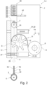
- Fig. 2 shows a schematic and sectional view of the strand bundling device 1, which has an additional element dispenser 38, by means of which an additional element 39 is provided to the strand 3 in the bundling area 6.
- the additional element dispenser 38 is designed as an additional element dispenser magazine in which several additional elements 39 are stored or stored.
- the additional element dispenser 38 has a dispenser mechanism 40, by means of which, in the present case, one of the additional elements 39 is placed on the strand 3 to be bundled for each bundling process.
- the additional element dispenser 38 is opened and closed again by means of the dispenser mechanism 40, so that exactly one of the stored additional elements 39 falls onto the strand 3 to be bundled.
- the additional element 39 is moved together with the strand 3 along the bundling direction b through the strand bundling unit 4, and the bundling strip 5 is thereby placed in a bay shape around the strand 3 with the additional element 39, whereby the additional element 39 is fixed to the strand 3 by means of the bundling strip 5.
- Fig. 2 further shows that the strand bundling device 1 or at least one of the strand bundling units 4 of the strand bundling device 1 can be used upright.
- the use of the additional element dispenser 38 is also possible with differently oriented strand bundling units 4, for example in connection with Fig. 1 orientation described.
- Fig. 3 shows a schematic view of the strand bundling device 1, in which two strand bundling units 4 are arranged next to each other.
- the two strand bundling units 4 are differentiated using the characters A, B.
- the bundling strip 5 is not shown, and the additional element dispenser 38 is shown transparently and only its contours are indicated.
- the strand 3 simultaneously enters the strand bundling units A, B and simultaneously leaves the strand bundling units A, B while moving relative to the strand bundling units A, B in the bundling direction b.
- the additional element dispenser 38 is arranged between the two parallel strand bundling units A, B.
- the strand bundling device 1 can have a further strand bundling unit 4, which is designated C below.
- the strand bundling units A, C can be arranged in series along the respective longitudinal direction x and fixed relative to one another, such that when the strand 3 emerges from the strand bundling unit A in the bundling direction b, the strand 3 in the bundling direction b into the serially arranged strand bundling unit C entry.
- the strand bundling device 1 can have a further strand bundling unit 4, which is marked D below.
- Fig. 5 a schematic view of the strand bundling device 1, with the two strand bundling units A, D, which are arranged opposite one another.
- the strand bundling units A, D are fixed relative to one another in such a way that the bundling directions b are arranged in opposite directions and parallel to one another. So around strand 3 To move completely through both strand bundling units A, D, the strand 3 is first moved relative to the strand bundling unit A along its bundling direction b through the associated bundling area 6.
- the strand 3 is then moved in a translation direction c, which can be even or odd, to the opposite strand bundling unit D, and is moved along its bundling direction b through the associated bundling area 6.
- the strand bundling units A, D can share a common counter-holder element 17.
- the strand bundling units A, D can have a common lock mechanism 21, whereby, for example, one of the lock elements 22, 23 can be arranged on the strand bundling unit A and another of the lock elements 22, 23 can be arranged on the strand bundling unit A.
- the lock elements 22, 23 can be arranged on the strand bundling unit A.
- the arrangement having the strand bundling units A, D can also have a further lock element 41, which, in conjunction with a further lock element 41 or 22, 23, allows the strand 3 to pass completely through the arrangement along the bundling direction(s) b or along the translation direction c is guaranteed.
- the further lock element 41 is attached to a support element 42, by means of which the strand bundling units A, D are fixed to one another.
- the strand bundling units 4 or A, B, C, D can each be designed the same or different from one another.
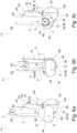
- Fig. 6 shows a schematic view of the feed device 11 of the strand bundling unit 4, where Fig. 6a shows an initial state of the application device 11.
- the application device 11 has a locking mechanism 43 with two locking arches 44, which can be pivoted in mirror image to one another via their respective first end 45 on a common pivot axis 46 and can be pivoted on the carrier device 7 (in Fig. 6 not shown).
- Respective second ends 47 of the locking arches 44 are connected by means of a reversibly elastic or flexible connecting band 48 and are spaced apart from one another in a rest position of the locking mechanism 43 that characterizes the initial state.
- the application device 11 has a transfer device 49, which includes a transfer arm 50 and a lever mechanism 51.
- the lever mechanism 51 has a release lever 52 and a gear lever 53, the release lever 52 and the takeover arm 50 being connected to one another in an articulated manner by means of the gear lever 53.
- the release lever 52 is mounted by means of a pivot bearing 54 in such a way that a release portion 55 of the release lever 52 projects into a feed area 56 of the strand bundling unit 4 to such an extent that the release portion 55, and thereby the release lever 52, is deflected when the strand 3 is in the bundling direction b is moved through the feed area 56.
- the release lever 52 When the strand 3 is moved along the bundling direction b and through the feed area 56 towards the bundling area 6, the release lever 52 is deflected. Due to the articulated connection between the release lever 52 and the takeover arm 50 by means of the gear lever 53, the bundling strip 5 is placed over the second ends 47 of the closing arches 44 and thereby over the connecting band 48 by means of the takeover arm 50. This is in Fig. 6b shown.
- the transfer arm 50 is pivotally mounted on the carrier device 7 by means of a further pivot bearing 57 and has a transfer element 59 at its distal end 58, such as a strip gripper etc., which is in the rest position and when laying the bundling strip 5 over the second ends 47 of the Closing arches 44 are connected to the bundling strip 5 in a non-destructively reversible and/or form-fitting manner.
- the takeover arm 50 is pivoted about its pivot bearing 57, the bundling strip 5 is pulled over the second ends 47 of the closing arches 44 and, in particular, tensioned.
- Fig. 6c shows a state of the application device 11 in which the bundling strip 5 is placed in a bay shape around and onto the strand 3 by means of the closing arches 44, in that the strand 3 is moved further along the bundling direction b towards and into the bundling area 6. It is in Fig. 6c On the one hand, it can be seen that after the strand 3 has passed the release lever 52 or its release part 55, the takeover arm 50 returns to its starting position (see Fig. 6a ) has swung back.
- the takeover arm can be pivoted back, for example, by means of a spring element (not shown), which is tensioned when the release lever 52 is deflected and, after the strand 3 has passed the release lever 502, relaxes and thereby swings the takeover arm 50 back.
- a spring element not shown
- Fig. 6c It can be seen that the strand 3, as it moves further into the bundling area 6, bends the bundling strip 5 placed over the second ends 47 in the middle and subsequently the connecting band 48 in the direction of the pivot axis 46, whereby the second ends 47 of the closing arches 44 come together to be moved.
- the closing mechanism 43 closes the closing mechanism 43, with the bundling strip 5 being placed in a bay shape around the strand 3 by means of the connecting band 48 and by means of the second ends 47 of the closing arches 44 which move towards one another.
- the strand 3 provided with the bundling strip 5 can then be removed through the feed area 56 against the bundling direction b - that is, along the bundling direction b.
- the release lever 52 can be designed to be bendable or flexible against the bundling direction b.
- Fig. 3 and Fig. 4 each show the system 2, which has one or more strand bundling devices 1 or one or more strand bundling units 4, the respective strand bundling device 1 or strand bundling unit 4 being attached to an auxiliary construction structure 60.
- the construction aid structure 60 can have the robot 20.
- the auxiliary construction structure 60 can have a building board 61 which is in Fig. 3 and Fig. 4 is shown.
- the building board 61 can be configured depending on the shape of the strand 3 to be formed by attaching the strand bundling device 1 to fastening points 62 that correspond to the strand shape.
- the building board 61 has a cutout 63 which corresponds to the strand 3 in shape and geometry.
- the strand bundling device 1 or strand bundling unit 4 is arranged at an edge of the cutout 63, whereby the bundling strip 5 can be attached to the strand 3 by means of the system 2.
- the building board 61 together with the strand bundling device 1 attached to it is moved over the strand 3 held on the clamping device in such a way that the strand 3 moves in the bundling direction b passes through the cutout 63 and is moved through the bundling area 6 of the strand bundling device 1.
- the strand 3 is then bundled and held on the clamping device.
- the clamping device with the pre-assembled and tensioned/stretched strand 3 is arranged above the building board 61, that is to say on the foot side of the bundling direction b.
- the strand is then moved in the bundling direction b through the bundling area 6 of the strand bundling device 1, after which the strand 3 bundled in this way, possibly together with the clamping device, falls freely through the cutout 63.
- the strand 3 is released from/from the clamping device before it is bundled as described.
- the strand 3 is released from the clamping device by moving the strand 3 through the cutout 63.
- the strand bundling device 1 and the system 2 show a respective possibility for producing a bundled strand, in particular a cable harness, particularly easily and with little effort. It is particularly advantageous that the strand 3, which has end elements 65 at its longitudinal ends 64 (foot side of the width direction b and tip side of the width direction b of the strand bundling device 1), which enable the strand bundling device 1 to be removed from the strand 3 along its longitudinal extension direction v impede.
- the strand bundling device 1 when used as intended, in particular in the method for bundling the strand 3 by means of the strand bundling device 1 and/or the system 2 having the strand bundling device 1, it is provided according to the invention that the strand 3 is moved at least after it has been bundled the bundling strip 5 is completely omitted.
Landscapes
- Engineering & Computer Science (AREA)
- Manufacturing & Machinery (AREA)
- Basic Packing Technique (AREA)
Applications Claiming Priority (1)
| Application Number | Priority Date | Filing Date | Title |
|---|---|---|---|
| DE102022109517.7A DE102022109517B4 (de) | 2022-04-20 | 2022-04-20 | Strangbündelungsvorrichtung und system zum bündeln eines strangs, insbesondere eines kabelbaums |
Publications (1)
| Publication Number | Publication Date |
|---|---|
| EP4266330A1 true EP4266330A1 (fr) | 2023-10-25 |
Family
ID=86006542
Family Applications (1)
| Application Number | Title | Priority Date | Filing Date |
|---|---|---|---|
| EP23167517.4A Pending EP4266330A1 (fr) | 2022-04-20 | 2023-04-12 | Dispositif et système de formation de faisceau de fils, en particulier un faisceau de fils |
Country Status (2)
| Country | Link |
|---|---|
| EP (1) | EP4266330A1 (fr) |
| DE (1) | DE102022109517B4 (fr) |
Citations (4)
| Publication number | Priority date | Publication date | Assignee | Title |
|---|---|---|---|---|
| US5410861A (en) * | 1993-04-13 | 1995-05-02 | Medlock; Harold G. | Apparatus for banding bunched articles |
| DE102017109819A1 (de) * | 2017-05-08 | 2018-11-08 | Lisa Dräxlmaier GmbH | Umwickeln eines Leitungssatzes mit Band |
| DE102019005933A1 (de) * | 2019-08-22 | 2020-02-27 | Daimler Ag | Verfahren und Vorrichtung zum Umwickeln eines Leitungssatzes für einen Kraftwagen mit einem Klebeband |
| CN113205921A (zh) * | 2021-04-06 | 2021-08-03 | 王海涛 | 一种汽车线束加工系统及汽车线束加工方法 |
-
2022
- 2022-04-20 DE DE102022109517.7A patent/DE102022109517B4/de active Active
-
2023
- 2023-04-12 EP EP23167517.4A patent/EP4266330A1/fr active Pending
Patent Citations (4)
| Publication number | Priority date | Publication date | Assignee | Title |
|---|---|---|---|---|
| US5410861A (en) * | 1993-04-13 | 1995-05-02 | Medlock; Harold G. | Apparatus for banding bunched articles |
| DE102017109819A1 (de) * | 2017-05-08 | 2018-11-08 | Lisa Dräxlmaier GmbH | Umwickeln eines Leitungssatzes mit Band |
| DE102019005933A1 (de) * | 2019-08-22 | 2020-02-27 | Daimler Ag | Verfahren und Vorrichtung zum Umwickeln eines Leitungssatzes für einen Kraftwagen mit einem Klebeband |
| CN113205921A (zh) * | 2021-04-06 | 2021-08-03 | 王海涛 | 一种汽车线束加工系统及汽车线束加工方法 |
Also Published As
| Publication number | Publication date |
|---|---|
| DE102022109517A1 (de) | 2023-10-26 |
| DE102022109517B4 (de) | 2024-02-01 |
Similar Documents
| Publication | Publication Date | Title |
|---|---|---|
| EP3503127B1 (fr) | Dispositif d'enroulement et procédé d'enroulement entièrement automatisé d'un faisceau de conducteurs à l'aide d'une bande adhésive | |
| DE3838706A1 (de) | Kabelbaum sowie verfahren und einrichtung zur herstellung desselben | |
| EP3058631A1 (fr) | Station de montage et procédé de pose automatisée d'attaches sur un faisceau de câbles et unité d'alimentation en attaches | |
| EP1884410A2 (fr) | Porte-charge | |
| DE102019213325A1 (de) | Montagekopf sowie Verfahren zur automatisierten Umwicklung eines Leitungsstrangs | |
| EP4402704B1 (fr) | Tête d'assemblage et procédé d'emballage d'un faisceau de câbles de manière automatisée | |
| DE202010001324U1 (de) | Vorrichtung zum Verdrillen von Leitungen | |
| DE69400472T2 (de) | Vorrichtung und Maschine zum Einfügen von Verbindungselementen in Verbindern | |
| DE102022109517B4 (de) | Strangbündelungsvorrichtung und system zum bündeln eines strangs, insbesondere eines kabelbaums | |
| DE102022101493B4 (de) | Herstellvorrichtung und verfahren zum herstellen eines kabelbaums | |
| CH681935A5 (fr) | ||
| DE102016117711B4 (de) | Verfahren zum Herstellen von Kabelanordnungen mittels eines Roboters, Wickelvorrichtung und Verlegeroboter | |
| DE112023005622T5 (de) | Kabelbaum-Herstellungsgerät und Kabelbaum-Herstellungsverfahren | |
| DE112015005805B4 (de) | Kabelhalter | |
| DE102016120626B3 (de) | Vorrichtung und verfahren zum verdrillen von leitungen in oder an einem bestückungsautomaten | |
| EP4451294A1 (fr) | Appareil, système et procédé d'assemblage de faisceaux de câbles | |
| DE102022116494B4 (de) | Stationäres vollautomatisiertes bandagieren und halteteilsetzen | |
| WO2024132392A1 (fr) | Conduit de câbles | |
| EP4713949A1 (fr) | Tête d'assemblage pour envelopper automatiquement un faisceau de câbles, système de changement et procédé de changement automatique d'une unité de cerclage dans la tête d'assemblage | |
| EP4431343A1 (fr) | Dispositif de fixation pour fixer un premier composant à un second composant et procédé de montage d'un tel dispositif de fixation | |
| EP4297049A1 (fr) | Procédé de bandage de faisceaux de câbles et de maintien de pièces | |
| DE102023120687A1 (de) | Befestigungsvorrichtung zum Befestigen eines ersten Bauteils an einem zweiten Bauteil sowie ein Verfahren zur Herstellung einer solchen Befestigungsvorrichtung | |
| EP1476050B1 (fr) | Procede pour enlever une liaison par agrafes pour meubles capitonnes | |
| DE102023115809A1 (de) | Vorrichtung und Verfahren zum Verlegen von Leitungen zur Ausbildung eines Leitungssatzes | |
| EP4617180A2 (fr) | Garrot pour la prise d'un coil de ligne |
Legal Events
| Date | Code | Title | Description |
|---|---|---|---|
| PUAI | Public reference made under article 153(3) epc to a published international application that has entered the european phase |
Free format text: ORIGINAL CODE: 0009012 |
|
| STAA | Information on the status of an ep patent application or granted ep patent |
Free format text: STATUS: THE APPLICATION HAS BEEN PUBLISHED |
|
| AK | Designated contracting states |
Kind code of ref document: A1 Designated state(s): AL AT BE BG CH CY CZ DE DK EE ES FI FR GB GR HR HU IE IS IT LI LT LU LV MC ME MK MT NL NO PL PT RO RS SE SI SK SM TR |
|
| STAA | Information on the status of an ep patent application or granted ep patent |
Free format text: STATUS: REQUEST FOR EXAMINATION WAS MADE |
|
| 17P | Request for examination filed |
Effective date: 20240403 |
|
| RBV | Designated contracting states (corrected) |
Designated state(s): AL AT BE BG CH CY CZ DE DK EE ES FI FR GB GR HR HU IE IS IT LI LT LU LV MC ME MK MT NL NO PL PT RO RS SE SI SK SM TR |
|
| STAA | Information on the status of an ep patent application or granted ep patent |
Free format text: STATUS: EXAMINATION IS IN PROGRESS |
|
| 17Q | First examination report despatched |
Effective date: 20251002 |