EP4265372B1 - Indexiervorrichtung - Google Patents
Indexiervorrichtung Download PDFInfo
- Publication number
- EP4265372B1 EP4265372B1 EP23164682.9A EP23164682A EP4265372B1 EP 4265372 B1 EP4265372 B1 EP 4265372B1 EP 23164682 A EP23164682 A EP 23164682A EP 4265372 B1 EP4265372 B1 EP 4265372B1
- Authority
- EP
- European Patent Office
- Prior art keywords
- pressing member
- hole
- gear
- intermediate shaft
- shaft
- Prior art date
- Legal status (The legal status is an assumption and is not a legal conclusion. Google has not performed a legal analysis and makes no representation as to the accuracy of the status listed.)
- Active
Links
Images


Classifications
-
- B—PERFORMING OPERATIONS; TRANSPORTING
- B23—MACHINE TOOLS; METAL-WORKING NOT OTHERWISE PROVIDED FOR
- B23Q—DETAILS, COMPONENTS, OR ACCESSORIES FOR MACHINE TOOLS, e.g. ARRANGEMENTS FOR COPYING OR CONTROLLING; MACHINE TOOLS IN GENERAL CHARACTERISED BY THE CONSTRUCTION OF PARTICULAR DETAILS OR COMPONENTS; COMBINATIONS OR ASSOCIATIONS OF METAL-WORKING MACHINES, NOT DIRECTED TO A PARTICULAR RESULT
- B23Q16/00—Equipment for precise positioning of tool or work into particular locations not otherwise provided for
- B23Q16/02—Indexing equipment
- B23Q16/022—Indexing equipment in which only the indexing movement is of importance
- B23Q16/025—Indexing equipment in which only the indexing movement is of importance by converting a continuous movement into a rotary indexing movement
-
- B—PERFORMING OPERATIONS; TRANSPORTING
- B23—MACHINE TOOLS; METAL-WORKING NOT OTHERWISE PROVIDED FOR
- B23Q—DETAILS, COMPONENTS, OR ACCESSORIES FOR MACHINE TOOLS, e.g. ARRANGEMENTS FOR COPYING OR CONTROLLING; MACHINE TOOLS IN GENERAL CHARACTERISED BY THE CONSTRUCTION OF PARTICULAR DETAILS OR COMPONENTS; COMBINATIONS OR ASSOCIATIONS OF METAL-WORKING MACHINES, NOT DIRECTED TO A PARTICULAR RESULT
- B23Q16/00—Equipment for precise positioning of tool or work into particular locations not otherwise provided for
- B23Q16/02—Indexing equipment
-
- F—MECHANICAL ENGINEERING; LIGHTING; HEATING; WEAPONS; BLASTING
- F16—ENGINEERING ELEMENTS AND UNITS; GENERAL MEASURES FOR PRODUCING AND MAINTAINING EFFECTIVE FUNCTIONING OF MACHINES OR INSTALLATIONS; THERMAL INSULATION IN GENERAL
- F16H—GEARING
- F16H1/00—Toothed gearings for conveying rotary motion
- F16H1/02—Toothed gearings for conveying rotary motion without gears having orbital motion
- F16H1/04—Toothed gearings for conveying rotary motion without gears having orbital motion involving only two intermeshing members
- F16H1/12—Toothed gearings for conveying rotary motion without gears having orbital motion involving only two intermeshing members with non-parallel axes
- F16H1/16—Toothed gearings for conveying rotary motion without gears having orbital motion involving only two intermeshing members with non-parallel axes comprising worm and worm-wheel
-
- F—MECHANICAL ENGINEERING; LIGHTING; HEATING; WEAPONS; BLASTING
- F16—ENGINEERING ELEMENTS AND UNITS; GENERAL MEASURES FOR PRODUCING AND MAINTAINING EFFECTIVE FUNCTIONING OF MACHINES OR INSTALLATIONS; THERMAL INSULATION IN GENERAL
- F16H—GEARING
- F16H1/00—Toothed gearings for conveying rotary motion
- F16H1/02—Toothed gearings for conveying rotary motion without gears having orbital motion
- F16H1/20—Toothed gearings for conveying rotary motion without gears having orbital motion involving more than two intermeshing members
-
- F—MECHANICAL ENGINEERING; LIGHTING; HEATING; WEAPONS; BLASTING
- F16—ENGINEERING ELEMENTS AND UNITS; GENERAL MEASURES FOR PRODUCING AND MAINTAINING EFFECTIVE FUNCTIONING OF MACHINES OR INSTALLATIONS; THERMAL INSULATION IN GENERAL
- F16H—GEARING
- F16H19/00—Gearings comprising essentially only toothed gears or friction members and not capable of conveying indefinitely-continuing rotary motion
- F16H19/08—Gearings comprising essentially only toothed gears or friction members and not capable of conveying indefinitely-continuing rotary motion for interconverting rotary motion and oscillating motion
-
- F—MECHANICAL ENGINEERING; LIGHTING; HEATING; WEAPONS; BLASTING
- F16—ENGINEERING ELEMENTS AND UNITS; GENERAL MEASURES FOR PRODUCING AND MAINTAINING EFFECTIVE FUNCTIONING OF MACHINES OR INSTALLATIONS; THERMAL INSULATION IN GENERAL
- F16H—GEARING
- F16H37/00—Combinations of mechanical gearings, not provided for in groups F16H1/00 - F16H35/00
- F16H37/02—Combinations of mechanical gearings, not provided for in groups F16H1/00 - F16H35/00 comprising essentially only toothed or friction gearings
- F16H37/04—Combinations of toothed gearings only
- F16H37/041—Combinations of toothed gearings only for conveying rotary motion with constant gear ratio
-
- F—MECHANICAL ENGINEERING; LIGHTING; HEATING; WEAPONS; BLASTING
- F16—ENGINEERING ELEMENTS AND UNITS; GENERAL MEASURES FOR PRODUCING AND MAINTAINING EFFECTIVE FUNCTIONING OF MACHINES OR INSTALLATIONS; THERMAL INSULATION IN GENERAL
- F16H—GEARING
- F16H57/00—General details of gearing
- F16H57/0018—Shaft assemblies for gearings
- F16H57/0031—Shaft assemblies for gearings with gearing elements rotatable supported on the shaft
-
- F—MECHANICAL ENGINEERING; LIGHTING; HEATING; WEAPONS; BLASTING
- F16—ENGINEERING ELEMENTS AND UNITS; GENERAL MEASURES FOR PRODUCING AND MAINTAINING EFFECTIVE FUNCTIONING OF MACHINES OR INSTALLATIONS; THERMAL INSULATION IN GENERAL
- F16H—GEARING
- F16H57/00—General details of gearing
- F16H57/02—Gearboxes; Mounting gearing therein
- F16H57/023—Mounting or installation of gears or shafts in the gearboxes, e.g. methods or means for assembly
-
- F—MECHANICAL ENGINEERING; LIGHTING; HEATING; WEAPONS; BLASTING
- F16—ENGINEERING ELEMENTS AND UNITS; GENERAL MEASURES FOR PRODUCING AND MAINTAINING EFFECTIVE FUNCTIONING OF MACHINES OR INSTALLATIONS; THERMAL INSULATION IN GENERAL
- F16H—GEARING
- F16H57/00—General details of gearing
- F16H57/02—Gearboxes; Mounting gearing therein
- F16H57/039—Gearboxes for accommodating worm gears
-
- F—MECHANICAL ENGINEERING; LIGHTING; HEATING; WEAPONS; BLASTING
- F16—ENGINEERING ELEMENTS AND UNITS; GENERAL MEASURES FOR PRODUCING AND MAINTAINING EFFECTIVE FUNCTIONING OF MACHINES OR INSTALLATIONS; THERMAL INSULATION IN GENERAL
- F16H—GEARING
- F16H57/00—General details of gearing
- F16H57/02—Gearboxes; Mounting gearing therein
- F16H2057/02039—Gearboxes for particular applications
- F16H2057/02069—Gearboxes for particular applications for industrial applications
- F16H2057/02073—Reduction gearboxes for industry
-
- F—MECHANICAL ENGINEERING; LIGHTING; HEATING; WEAPONS; BLASTING
- F16—ENGINEERING ELEMENTS AND UNITS; GENERAL MEASURES FOR PRODUCING AND MAINTAINING EFFECTIVE FUNCTIONING OF MACHINES OR INSTALLATIONS; THERMAL INSULATION IN GENERAL
- F16H—GEARING
- F16H57/00—General details of gearing
- F16H57/02—Gearboxes; Mounting gearing therein
- F16H57/021—Shaft support structures, e.g. partition walls, bearing eyes, casing walls or covers with bearings
- F16H2057/0213—Support of worm gear shafts
Definitions
- the present invention relates to an indexing device configured to index an angular position of a drive target object by using a drive motor as a drive source, and including a drive transmission mechanism including a first gear attached to an output shaft of the drive motor, a second gear attached to a drive shaft for driving the drive target obj ect, and an intermediate gear configured to transmit rotation of the first gear to the second gear and rotatably supported with respect to an intermediate shaft fixed to a frame, the intermediate shaft being inserted at an end portion into an accommodation hole formed in the frame.
- a drive transmission mechanism including a first gear attached to an output shaft of the drive motor, a second gear attached to a drive shaft for driving the drive target obj ect, and an intermediate gear configured to transmit rotation of the first gear to the second gear and rotatably supported with respect to an intermediate shaft fixed to a frame, the intermediate shaft being inserted at an end portion into an accommodation hole formed in the frame.
- a rotation indexing device including a main shaft having one end to which a table on which a workpiece is placed is fixed, and a drive motor serving as a drive source for rotationally driving the main shaft, and configured to index an angular position of the table as a drive target object by rotationally driving the main shaft with the drive motor.
- the rotation indexing device has a drive transmission mechanism for transmitting drive of the drive motor to the main shaft, in its frame.
- the drive transmission mechanism includes a drive shaft for rotationally driving the main shaft (table), a gear (first gear) attached to an output shaft of the drive motor and a gear (second gear) attached to the drive shaft.
- the drive transmission mechanism there is one having a gear (intermediate gear) for transmitting rotation of the first gear to the second gear.
- Patent Literature 1 discloses a rotation indexing device including such an intermediate gear.
- the device of Patent Literature 1 is a rotation indexing device in which the drive shaft in the drive transmission mechanism described above is a worm shaft. That is, the drive transmission mechanism in the rotation indexing device (hereinafter, referred to as 'existing device') in Patent Literature 1 includes a so-called worm gear mechanism configured by a worm wheel attached to the main shaft and a worm shaft including a worm in mesh with the worm wheel.
- the intermediate gear is supported by an intermediate shaft provided in a form of being inserted into a shaft hole (accommodation hole) of the frame at an end portion. Note that, the intermediate shaft is non-rotatably fixed to the frame, and the intermediate gear is rotatably supported with respect to the intermediate shaft.
- the intermediate shaft is formed at the end portion inserted into the accommodation hole with a plurality of female screw holes opened to an end face thereof and penetrating toward an axis line direction and through-holes each penetrating from each female screw hole toward an outer peripheral surface.
- the locking screw is screwed into the female screw hole at the end portion of the intermediate shaft, and is configured as a so-called tapered locking screw with a tapered surface at a tip end portion.
- the steel ball is disposed in each of the through-holes at the end portion of the intermediate shaft, and the locking screw is screwed into each of the female screw holes, so that the steel ball is disposed between the tapered surface of the locking screw and an inner peripheral surface of the accommodation hole. Further, by tightening the locking screw so as to be displaced in the axis line direction and thus applying an axial pressing force to the steel ball, a radial force acts on the inner peripheral surface of the accommodation hole via the steel ball, and the intermediate shaft is fixed to the frame.
- Patent Literature 1 JPS63-067052U
- the intermediate shaft is provided such that its end face is exposed to an outside, and along with this, the opening of each female screw hole formed at the end portion thereof is also exposed to the outside.
- the locking screw is screwed into each female screw hole, so that each female screw hole is in a closed state.
- each female screw hole and the locking screw are combined with each other by screwing, there is a slight gap therebetween.
- a seal member cannot be provided between the female screw hole and the locking screw.
- the coolant liquid when the coolant liquid is applied to the rotation indexing device as described above and reaches the opening of each female screw hole exposed to the outside as described above at the intermediate shaft, the coolant liquid may pass through the gap between the female screw hole and the locking screw and then infiltrate into the frame via the through-hole in communication with the female screw hole.
- the coolant liquid is mixed with the lubricating oil stored so as to lubricate the drive transmission mechanism in the frame, so that the lubrication performance of the lubricating oil is lowered.
- a countermeasure of applying a liquid sealant to a male screw portion of the locking screw is also considered.
- the applying of the sealant is performed manually by an operator, unevenness in application may occur depending on the operator, and therefore, the countermeasure lacks in certainty with respect to infiltration prevention of the coolant liquid.
- the present invention is to provide an indexing device with a configuration capable of preventing infiltration of the coolant liquid into a frame more reliably.
- the invention is defined in claim 1.
- a mechanism for displacing the pressing member in contact with the steel ball on the tapered surface in the axis line direction uses the screw member inserted into the insertion hole of the pressing member formed as described above and screwed into the female screw hole of the intermediate shaft, not the screw mechanism between the pressing member and the intermediate shaft as in the existing device.
- the displacement mechanism is configured such that the screw member configured to be displaced in the axis line direction by being tightened with respect to the intermediate shaft pushes the pressing member along with the displacement, thereby displacing the pressing member in the axis line direction.
- the fixing mechanism can be configured such that an outer peripheral surface of the pressing member is brought into contact with a part (member) around of the pressing member over the entire circumference in the accommodation hole of the frame.
- a seal member such as an O-ring between the outer peripheral surface of the pressing member and the part around the pressing member. Therefore, according to the indexing device of the present invention in which the fixing mechanism (displacement mechanism) is configured as described above, when the seal member is disposed appropriately in this way, infiltration of the coolant liquid into the frame can be prevented as much as possible, and therefore, the lubrication performance of the lubricating oil can be prevented from being lowered.
- the present embodiment is an example in which the indexing device is a so-called rotary table device having a table on which a workpiece is placed, and configured to index an angular position of the table.
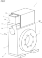
- FIG. 1 schematically shows an appearance of a rotary table device 1.
- the rotary table device 1 includes, as its constituent elements, a frame 10 installed on an installation surface (not shown) of a working machine, and a table 3 on which a workpiece is placed.
- the rotary table device 1 is a so-called vertical-type rotary table device installed so that a placement surface of the table 3 on which a workpiece is placed is perpendicular to the installation surface.
- the rotary table device 1 is configured to use a drive motor as a drive source and to index an angular position of the table 3 by rotating the table 3 serving as a drive target object by the drive motor.
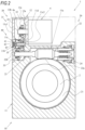
- the frame 10 has, as a main body, a main frame part 11, which occupies most of the frame 10, as shown in FIG. 2 .
- the rotary table device 1 includes a main shaft 2 having one end to which the table 3 is attached.
- the main shaft 2 is rotatably supported with respect to the frame 10 (main frame part 11) via a bearing (not shown), in an accommodation space formed in the main frame part 11 of the frame 10.
- the table 3 is also attached to the main shaft 2 in such a way that the placement surface is exposed to a surface orthogonal to both side surfaces of the main frame part 11.
- the main frame part 11 of the frame 10 has a worm shaft hole 11a in which a worm shaft of a drive transmission mechanism described later is accommodated.
- the worm shaft hole 11a is formed to penetrate through the main frame part 11 in a form of communicating with the accommodation space and opened to both side surfaces of the main frame part 11.
- the frame 10 includes a sub-frame part 12 to which the drive motor 4 serving as a drive source is attached.
- the sub-frame part 12 has a substantially rectangular parallelepiped shape in appearance and a space (internal space) 12a formed therein, and is configured by a peripheral wall portion 12b mainly composed of four peripheral walls so that the internal space 12a is opened upwards and downwards, and a plate-shaped cover portion 12c combined to the peripheral wall portion 12b so as to close the upper opening of the peripheral wall portion 12b.
- the drive motor 4 is attached to an outer surface of one (attachment wall) of the peripheral walls of the peripheral wall portion 12b of the sub-frame part 12 with an output shaft 4a facing toward the sub-frame part 12.
- the attachment wall of the peripheral wall portion 12b is formed with a through-hole penetrating through the attachment wall so as to allow the drive motor 4 to be attached.
- the sub-frame part 12 is attached to an upper surface (a surface opposite to a surface that is installed to the working machine) of the main frame part 11 in such an arrangement that a position of an outer surface of a peripheral wall parallel to the attachment wall with respect to a width direction of the frame 10 (penetration direction of the worm shaft hole 11a) is matched with a position of the side surface on one side of the main frame part 11. Note that, a portion on the upper surface of the main frame part 11 to which the sub-frame part 12 is attached is formed to protrude upward.
- a protruding portion (protrusion) 11c of the main frame part 11 is configured to have therein a space (communication space) 11d that communicates with the worm shaft hole 11a, and to have an opening on an upper surface side so that the communication space 11d is opened upward.
- the rotary table device 1 includes a drive transmission mechanism 30 for transmitting drive of the drive motor 4 to the main shaft 2.
- the drive transmission mechanism 30 includes a worm gear mechanism 20 configured by a worm wheel 21 attached to the main shaft 2 and a worm shaft 22 in mesh with the worm wheel 21.
- the worm wheel 21 is attached to the main shaft 2 so as not to be relatively rotatable at a position overlapping the worm shaft hole 11a with respect to an axis line direction of the main shaft 2, within the accommodation space in the frame 10 (main frame part 11).
- the worm shaft 22 includes a worm 22a in mesh with the worm wheel 21.
- the worm shaft 22 is rotatably supported with respect to the main frame part 11 (worm shaft hole 11a) on both sides of the worm 22a by bearings 23 and 24 in the worm shaft hole 11a of the main frame part 11. Further, the worm shaft 22 is in mesh with the worm wheel 21 at the worm 22a.
- the drive transmission mechanism 30 includes a gear train 31 configured by a combination of a plurality of gears, and is configured to connect the worm shaft 22 to the output shaft 4a of the drive motor 4 via the gear train 31.
- the gear train 31 includes a first gear 32 attached to the end portion of the output shaft 4a of the drive motor 4, and a second gear 33 attached to a shaft portion 22b on one end side (the side surface side on one side with respect to the bearing 23) with respect to the worm 22a of the worm shaft 22.
- the gear train 31 includes an intermediate gear 34 for transmitting rotation of the first gear 32 to the second gear 33.
- the intermediate gear 34 is configured to connect the first gear 32 and the second gear 33 each other.
- the intermediate gear 34 is a so-called two-stage gear configured by combining two gears with different numbers of teeth.
- one of the two gears is connected to the first gear 32, and the other is connected to the second gear 33.
- the intermediate gear 34 is supported by an intermediate shaft 35 provided in the communication space 11d in a form of being bridged on both sidewalls 11c1 and 11c2 of the protrusion 11c of the main frame part 11.
- the protrusion 11c of the main frame part 11 on which the intermediate shaft 35 is bridged is formed with a through-hole 11b serving as an accommodation hole in the sidewall 11c1 on an outer side (the side surface side on one side of the main frame part 11) of both the sidewalls 11c1 and 11c2.
- a through-hole 11b serving as an accommodation hole in the sidewall 11c1 on an outer side (the side surface side on one side of the main frame part 11) of both the sidewalls 11c1 and 11c2.
- an inner diameter of the accommodation hole 11b is substantially the same as an outer diameter of one end portion 35a, which is a portion on one end side of the intermediate shaft 35.
- the intermediate shaft 35 is supported on the outer sidewall 11c1 of the protrusion 11c at one end portion 35a in a state of being inserted into the accommodation hole 11b.
- the sidewall 11c2 (sidewall facing the outer sidewall 11c1) on an inner side of the protrusion 11c is formed with a circular groove opened in an inner peripheral surface thereof.
- the circular groove is formed such that a center thereof coincides with a center of the accommodation hole 11b as seen in the width direction and an inner diameter thereof is substantially the same as the inner diameter of the accommodation hole 11b.
- the intermediate shaft 35 is supported on the inner sidewall 11c2 of the protrusion 11c on the other end side in a form of being inserted into the circular groove. Note that, the intermediate shaft 35 is formed so that one end portion 35a inserted into the accommodation hole 11b is a large-diameter portion having a larger outer diameter than other portions.
- an outer diameter of one end portion 35a is larger than an outer diameter of the portion on the other end side.
- a bush 36 is attached to the circular groove in a fitting manner, and the intermediate shaft 35 is supported on the other end side in a form of being inserted into the bush 36.
- the intermediate shaft 35 is made non-rotatable with respect to the protrusion 11c by a fixing mechanism described later while being supported in this way.
- the intermediate gear 34 is rotatably supported with respect to the intermediate shaft 35 via a bearing.
- the fixing mechanism for fixing the intermediate shaft 35 to the frame 10 includes: a pressing member having a tapered surface and accommodated in an accommodating concave portion formed at one end portion 35a of the intermediate shaft 35; a screw member inserted into an insertion hole of the pressing member and screwed into a female screw hole of the intermediate shaft 35; and a steel ball disposed in the through-hole formed in the intermediate shaft 35 and mounted between the tapered surface of the pressing member and an inner peripheral surface of the accommodation hole 11b.
- the present embodiment is an example in which the entire tapered surface of the pressing member is located in the accommodating concave portion, and the pressing member is provided so as to slide with respect to the inner peripheral surface of the accommodating concave portion.
- the configuration of the rotary table device 1 including such a fixing mechanism will be described in detail with reference to FIGS. 3 and 4 .
- one end portion 35a of the intermediate shaft 35 is formed with an accommodating concave portion 35c, which is a concave portion opened to an end face on the one end side.
- the accommodating concave portion 35c is circular as seen in the axis line direction of the intermediate shaft 35, and is formed so that a center coincides with a shaft center (a center of an outer peripheral edge of one end portion 35a) of the intermediate shaft 35. That is, one end portion 35a of the intermediate shaft 35 is configured to have a space opened to an outside within a peripheral wall 35d around the accommodating concave portion 35c.
- the intermediate shaft 35 is formed with three through-holes 35e (only one visible in a cross section is shown in the drawing) radially penetrating through the peripheral wall 35d around the accommodating concave portion 35c.
- the three through-holes 35e are formed at equal intervals in a circumferential direction of the peripheral wall 35d.
- the pressing member 42 is a member formed mainly in a cylindrical shape. However, one end side of a peripheral surface of the pressing member 42 is formed to be a tapered surface 42a1. In this way, the pressing member 42 is configured by a tapered portion 42a, at which a peripheral surface on one end side of the pressing member is formed as a tapered surface 42a1, and a cylindrical portion 42b, which is a portion on the other end side with respect to the tapered portion 42a. In addition, an outer diameter of the cylindrical portion 42b is substantially the same as the inner diameter of the accommodating concave portion 35c of the intermediate shaft 35.
- the pressing member 42 is formed so that its dimension in the axis line direction is substantially the same as a depth dimension of the accommodating concave portion 35c of the intermediate shaft 35.
- the pressing member 42 is configured such that a dimension of the tapered portion 42a and a dimension of the cylindrical portion 42b are substantially the same in the axis line direction, i.e., one end side with respect to a substantial center position is the tapered portion 42a and the other end side is the cylindrical portion 42b.
- the pressing member 42 is formed with an insertion hole 42c penetrating through the pressing member 42 in the axis line direction.
- the insertion hole 42c is formed such that a center thereof coincides with the shaft center of the pressing member 42 (cylindrical portion 42b) as seen in the axis line direction of the pressing member 42.
- the insertion hole 42c is formed such that an inner diameter thereof changes at a substantially intermediate position in the axis line direction of the pressing member 42, and an inner diameter on one end side (taper portion 42a side) is smaller than an inner diameter on the other end side (cylindrical portion 42b side). That is, the insertion hole 42c is formed to have a stepped portion including an end face 42d facing toward the other end side.
- each through-hole 35e of the intermediate shaft 35 a steel ball 41 that is a spherical body is disposed.
- the accommodating concave portion 35c is formed such that a thickness of the peripheral wall 35d around the accommodating concave portion 35c in which the through-hole 35e is formed is slightly smaller than a diameter of the steel ball 41.
- the diameter of the steel ball 41 is slightly larger than the thickness of the peripheral wall 35d.
- the through-hole 35e is formed so that an inner diameter thereof is substantially the same as the diameter of the steel ball 41.
- the steel balls 41 are disposed (accommodated) in the respective through-holes 35e of the intermediate shaft 35 inserted into the accommodation hole 11b at one end portion 35a, the steel balls 41 are each in contact with the inner peripheral surface of the through-hole 35e and the inner peripheral surface of the accommodation hole 11b and a portion of the steel ball 41 protrudes inward from the inner peripheral surface of the peripheral wall 35d.
- the pressing member 42 is accommodated in a form of being inserted into the accommodating concave portion 35c of the intermediate shaft 35 in a direction in which the axis line direction of the pressing member coincides with the axis line direction of the intermediate shaft 35 and the tapered portion 42a becomes the bottom surface 35g side of the accommodating concave portion 35c with respect to the cylindrical portion 42b.
- the pressing member 42 comes into contact with the steel ball 41, which protrudes from the inner peripheral surface of the peripheral wall 35d as described above, on the tapered surface 42a1 of the tapered portion 42a.
- the fixing mechanism 40 is configured so that the pressing member 42 (cylindrical portion 42b) slides with respect to the inner peripheral surface of the accommodating concave portion 35c in a state where the pressing member 42 is accommodated in the accommodating concave portion 35c. For this reason, with respect to the axis line direction of the intermediate shaft 35, the position of the steel ball 41 at one end portion 35a, i.e., the position where the through-hole 35e in which the steel ball 41 is accommodated is formed is close to (near) the bottom surface 35g of the accommodating concave portion 35c.
- the inner diameter of the through-hole 35e is substantially the same as the diameter of the steel ball 41, but the dimension (depth dimension of the accommodating concave 35c), in the axis line direction of the intermediate shaft 35, of the peripheral wall 35d in which the through-hole 35e is formed is about a half of one end portion 35a with respect to the dimension in the axis line direction of the intermediate shaft 35.
- the tapered portion 42a of the pressing member 42 is formed so that an angle of the tapered surface 42a1 is such an angle that a gap 44 exists between an end face 42e on one end side of the pressing member 42 and the bottom surface 35g of the accommodating concave portion 35c in the state (accommodated state) where, as described above, the pressing member 42 is accommodated in the accommodating concave portion 35c and the steel ball 41 is in contact with the tapered surface 42a1 and the inner peripheral surface of the accommodation hole 11b.
- a position, on the tapered surface 42a1, of a contact point P between the tapered surface 42a1 of the tapered portion 42a of the pressing member 42 and the steel ball 41 and a distance A from the contact point P to the bottom surface 35g of the accommodating concave portion 35c, with respect to the axis line direction of the intermediate shaft 35 correspond to an angle of the tapered surface 42a1, more specifically, an angle (taper angle) ⁇ of the tapered surface 42a1 with respect to the axis line of the pressing member 42 ( FIG.
- a distance B from the contact point P to the end face 42e on one end side of the pressing member 42 corresponds to the position of the contact point P on the tapered surface 42a1.
- the distances A and B increase, and as the taper angle ⁇ decreases, the distances A and B decrease.
- the change in the distances A and B with respect to the change is larger in the distance B.
- the taper angle ⁇ when a pressing force is applied to the pressing member 42 in the axis line direction, the pressing force also acts on the steel ball 41, and a radial force also acts on the steel ball 41 by an action of the tapered surface 42a1. Further, the radial force increases as the taper angle ⁇ decreases.
- the taper angle ⁇ of the tapered portion 42a of the pressing member 42 is an angle at which, when a predetermined pressing force is applied to the pressing member 42, the radial force acting on the steel ball 41 becomes a desired degree of force.
- the taper angle ⁇ is an angle at which the distance A is larger than the distance B, i.e., the gap 44 exists between the end face 42e on one end side of the pressing member 42 and the bottom surface 35g of the accommodating concave portion 35c in the state where the tapered portion 42a is in contact with the steel ball 41.
- the fixing mechanism 40 is provided with a screw member 43 for applying a force to displace the pressing member 42 in the accommodated state toward the bottom surface 35g of the accommodating concave portion 35c.
- the screw member 43 is provided in a form of being inserted into the insertion hole 42c of the pressing member 42 in the accommodated state and screwed into the intermediate shaft 35. Therefore, the intermediate shaft 35 is formed with a female screw hole 35f formed so that it is opened to the bottom surface 35g of the accommodating concave portion 35c and a center thereof coincides with the center of the insertion hole 42c of the pressing member 42 in the accommodated state as seen in the axis line direction of the intermediate shaft 35. The screw member 43 is screwed into the female screw hole 35f.
- the screw member 43 is a screw member such as a bolt having a head portion.
- an inner diameter on one end side is smaller than a size (outer diameter) of the head portion.
- an inner diameter on the other end side (cylindrical portion 42b side) of the insertion hole 42c is larger than the size of the head portion. Therefore, in the state where the screw member 43 is inserted into the insertion hole 42c as described above, the screw member 43 is in a state where the head portion can come into contact with the end face 42d in the insertion hole 42c of the pressing member 42.
- the screw member 43 is screwed into the female screw hole 35f of the intermediate shaft 35, so that the head portion comes into contact with the end surface 42d.
- the female screw hole 35f is formed to have such a depth dimension that the screw member 43 can be further screwed from the state where the head portion of the screw member 43 is in contact with the end face 42d.
- seal member 51 is mounted between the head portion of the screw member 43 and the end face 42d of the pressing member 42.
- seal members 52 and 53 such as O-rings are each mounted between the outer peripheral surface of the cylindrical portion 42b of the pressing member 42 and the inner peripheral surface of the peripheral wall 35d of the intermediate shaft 35 and between the outer peripheral surface of the peripheral wall 35d and the inner peripheral surface of the accommodation hole 11b.
- the seal member 53 mounted between the outer peripheral surface of the peripheral wall 35d and the inner peripheral surface of the accommodating hole 11b is provided on an outermore side (an opposite side to the bottom surface 35g side of the accommodating concave portion 35c) than the position of the through-hole 35e with respect to the axis line direction of the intermediate shaft 35.
- the pressing member 42 is intended to be displaced (is applied with a displacing force) toward the bottom surface 35g side of the accommodating concave portion 35c, so that the pressing force acts on the steel ball 41.
- the mechanism to displace the pressing member 42 is not a mechanism in which the screw action for displacement is directly generated on the pressing member by screwing the pressing member into the intermediate shaft, as in the related art, but is a mechanism in which the screw member 43 provided with respect to the pressing member 42, as described above, is screwed into the intermediate shaft 35 and the screw action for displacement indirectly acts on the pressing member 42 via the screw member 43.
- the pressing member 42 and the intermediate shaft 35 can be configured such that the outer peripheral surface of the cylindrical portion 42b and the inner peripheral surface of the accommodating concave portion 35c are formed into a planar shape and they are in contact with each other on the planar surfaces. According to this configuration, it is possible to arrange a seal member such as an O-ring between the outer peripheral surface of the cylindrical part 42b and the inner peripheral surface of the accommodating concave portion 35c.
- the seal member 52 is arranged between the pressing member 42 and the intermediate shaft 35, as described above, so that even when the coolant liquid applied to the rotary table device 1 reaches a portion between the pressing member 42 and the intermediate shaft 35, the seal member 52 prevents the coolant liquid from being infiltrated into the frame 10 between the pressing member 42 and the intermediate shaft 35.
- the screw member 43 functioning as described above is provided in the form of being inserted into the insertion hole 42c for the pressing member 42, but is provided to be in contact with the end face 42d orthogonal to the insertion direction at the head portion. Accordingly, the configuration enables a sealing member to be disposed between the screw member 43 and the pressing member 42.
- the seal member 51 is also provided between the head portion of the screw member 43 and the end face 42d of the pressing member 42, as described above. Thereby, also between the screw member 43 and the pressing member 42, the seal member 51 prevents the coolant liquid from being infiltrated into the frame 10.
- the seal members are appropriately disposed as described above and the infiltration of the coolant liquid into the frame 10 is prevented, so that it is possible to prevent the problem that the lubrication performance of the lubricating oil stored in the frame 10 is lowered, as much as possible.
- a pressing member 62 is formed so that an outer diameter of a cylindrical portion 62b is substantially the same as the inner diameter of the accommodation hole 11b of the frame 10.
- the fixing mechanism is configured so that the pressing member 62 is provided in such a form that a tapered portion 62a is inserted into the accommodating concave part 35c of the intermediate shaft 35 and the cylindrical portion 62b is inserted into the accommodation hole 11b of the frame 10. Accordingly, in this configuration, the sliding of the pressing member 62 is guided at the cylindrical portion 62b on the inner peripheral surface of the accommodation hole 11b formed in the frame 10 (main frame part 11).
- the tapered portion 62a is formed to have such a dimension that, in a state where the pressing member 62 (tapered portion 62a) is in contact with the steel ball 41, the tapered portion exists in a form of further protruding outward than the intermediate shaft 35 (accommodating concave portion 35c) with respect to the axis line direction of the pressing member 62, i.e., a gap exists between an end face on one end side (tapered portion 62a side) of the cylindrical portion 62 and an end face (tip end of the peripheral wall 35d) on one end side of the intermediate shaft 35.
- the entire tapered surface 62a1 of the pressing members 62 is not located within the accommodating concave portion 35c, as in the above embodiment, but a part thereof is located within the accommodating concave portion 35c.
- a seal member such as an O-ring is placed between the outer peripheral surface of the cylindrical portion 62b of the pressing member 62 and the inner peripheral surface of the accommodation hole 11b.
- the pressing member 42 is configured only by the tapered portion 42a, which is a portion of the tapered surface 42a1 in contact with the steel ball 41, and the cylindrical portion 42b, which is a portion that slides with respect to the intermediate shaft 35.
- the pressing member is not limited to the configuration in which it consists of only the tapered portion and the cylindrical portion in this way, and may also be configured to have, in addition to the tapered portion and the cylindrical portion, for example, a cylinder-shaped portion that is continuous on an opposite side of the cylindrical portion to the tapered portion.
- the insertion hole 42c of the pressing member 42 is formed as a hole whose inner diameter on one end side is smaller than the head portion of the screw member 43 and inner diameter on the other end side is larger than the head portion of the screw member 43, and the head portion of the screw member 43 is inserted into the portion on the other end side.
- the insertion hole of the pressing member is not limited to the configuration in which the inner diameter on the other end side is formed large as such, and may also be formed as a hole whose inner diameter is uniform throughout and is smaller than the head portion of the screw member.
- the head portion of the screw member is in contact with the end face on the other end side of the pressing member (applies the pressing force to the end face on the other end side) in a state where the screw member is screwed into the intermediate shaft 35.
- the fixing mechanism 40 has such a configuration that the intermediate shaft 35 has three through-holes 35e and the three steel balls 41 are each disposed in each of the three through-holes 35e.
- the number of steel balls may be two or more, and the number is not particularly limited.
- the number of through-holes is not limited to the same number as the number of steel balls, and may be equal to or larger than the number of steel balls. That is, the present invention is not limited to the configuration where the steel balls are disposed in all the through-holes.
- n (n ⁇ 3) through-holes may be formed and the steel balls may be disposed in the appropriately selected through-holes whose number is smaller than n.
- the drive transmission mechanism 30 is configured such that the intermediate gear 34 is a so-called two-stage gear formed by combining two gears.
- the drive transmission mechanism may be configured such that when it is not necessary to change a reduction ratio by the intermediate gear, the intermediate gear is not the two-stage gear as in the above embodiment, but a so-called one-stage gear (idle gear) having one gear.
- the drive transmission mechanism 30 is configured such that only one set of the intermediate gear 34 and the intermediate shaft 35 configured to support the intermediate gear 34 is provided. That is, the drive transmission mechanism 30 is configured so that the first gear 32 and the second gear 33 are directly connected to each other via one intermediate gear 34.
- the indexing device that is the preamble of the present invention
- the present invention can also be applied to an indexing device (drive transmission mechanism) having such two or more intermediate gears and an intermediate shaft configured to support each intermediate gear.
- the intermediate shaft 35 is formed so that the outer diameter of one end portion 35a inserted into the accommodation hole 11b is larger than the outer diameters of the other portions.
- the intermediate shaft is not limited to such a shape, and may be formed so that the outer diameter is uniform throughout, for example.
- the drive transmission mechanism 30 adopts the so-called worm gear mechanism 20 configured by the worm wheel 21 attached to the main shaft 2 and the worm shaft 22 having the worm 22a in mesh with the worm wheel 21.
- the drive transmission mechanism is not limited to employing such a worm gear mechanism.
- a roller gear cam mechanism may be adopted which includes a roller gear where a plurality of rollers are arranged in a circumferential direction and a roller cam shaft having a spiral cam groove in mesh with the roller gear.
- a so-called ball drive mechanism ball decelerator configured so that a worm wheel and a worm shaft are indirectly engaged with each other via a ball serving as an engaging member may also be adopted.
- the present invention is applied to a so-called rotary table device having a table on which a workpiece is placed and configured to index the angular position of the table.
- the indexing device to which the present invention is applied is not limited to such a rotary table device.
- other indexing devices such as a milling head (spindle head) having a main spindle serving as a drive target supported by a support shaft corresponding to the main shaft, and configured to index an angular position of the main spindle around an axis of the support shaft are also possible.
Landscapes
- Engineering & Computer Science (AREA)
- General Engineering & Computer Science (AREA)
- Mechanical Engineering (AREA)
- Machine Tool Units (AREA)
- Gears, Cams (AREA)
- Transmission Devices (AREA)
Claims (1)
- Indexiervorrichtung (1), die konfiguriert ist zum Indexieren einer Winkelposition eines Antriebszielobjekts (3) durch Verwenden eines Antriebsmotors (4) als eine Antriebsquelle, und umfassend:
einen Antriebsübertragungsmechanismus (30), aufweisend:ein erstes Zahnrad (32), das an einer Ausgangswelle (4a) des Antriebsmotors befestigt ist;ein zweites Zahnrad (33), das an einer Antriebswelle (22) zum Antreiben des Antriebszielobjekts befestigt ist, undein Zwischenzahnrad (34), das konfiguriert ist zum Übertragen einer Drehung des ersten Zahnrads auf das zweite Zahnrad, und in Bezug auf eine Zwischenwelle (35) drehbar gelagert ist, die an einem Rahmen (10) angebracht ist, wobei die Zwischenwelle an einem Endabschnitt in ein Aufnahmeloch (11b) eingesetzt ist, das in dem Rahmen ausgebildet ist, wobei die Zwischenwelle (35) aufweist:einen aufnehmenden konkaven Abschnitt (35c), der eine Lochform mit Boden besitzt, der an dem Endabschnitt ausgebildet ist, zu einer Endfläche geöffnet ist, und so ausgebildet ist, dass er eine Mitte besitzt, die mit einer Mitte einer äußeren Umfangskante der Endfläche übereinstimmt, wie in einer Achslinienrichtung gesehen; undeine Vielzahl von Durchgangslöchern (35e), die eine Umfangswand (35d) um den aufnehmenden konkaven Abschnitt herum radial durchdringen, undeinen Anbringungsmechanismus (40) zum Anbringen der Zwischenwelle an dem Rahmen, dadurch gekennzeichnet, dass der Anbringungsmechanismus aufweist:ein zylindrisches Druckelement (42), das eine konische Oberfläche (42a1) an einer Umfangsoberfläche besitzt, ein Einsetzloch (42c) besitzt, das in der Achslinienrichtung an einer Mittelposition durchdringt und derart bereitgestellt ist, dass die konische Oberfläche einer Bodenoberfläche (35g) des aufnehmenden konkaven Abschnitts (35c) zugewandt ist und sich mindestens ein Abschnitt der konischen Oberfläche (42a1) in dem aufnehmenden konkaven Abschnitt befindet;Stahlkugeln (41), die in jedem Durchgangsloch (35e) angeordnet sind und einen größeren Durchmesser als eine Dicke der Umfangswand (35d) besitzen; undein Schraubenelement (43), das in das Einsetzloch (42c) des Druckelements (42) eingesetzt und in ein Innengewindeloch (35f) geschraubt ist, das zu der Bodenfläche (35g) geöffnet ist,wobeiein Spalt (44) zwischen dem Druckelement (42) und der Bodenoberfläche (35g) in einem Zustand vorhanden ist, in dem das Druckelement in dem aufnehmenden konkaven Abschnitt (35c) aufgenommen ist und die Stahlkugel (41), die in jedem Durchgangsloch (35e) aufgenommen ist, mit der konischen Oberfläche (42a1) und einer inneren Umfangsoberfläche des Aufnahmelochs (11b) in Kontakt ist.
Applications Claiming Priority (1)
| Application Number | Priority Date | Filing Date | Title |
|---|---|---|---|
| JP2022069899A JP7768824B2 (ja) | 2022-04-21 | 2022-04-21 | 割出し装置 |
Publications (2)
| Publication Number | Publication Date |
|---|---|
| EP4265372A1 EP4265372A1 (de) | 2023-10-25 |
| EP4265372B1 true EP4265372B1 (de) | 2025-01-01 |
Family
ID=85778763
Family Applications (1)
| Application Number | Title | Priority Date | Filing Date |
|---|---|---|---|
| EP23164682.9A Active EP4265372B1 (de) | 2022-04-21 | 2023-03-28 | Indexiervorrichtung |
Country Status (7)
| Country | Link |
|---|---|
| US (1) | US12090594B2 (de) |
| EP (1) | EP4265372B1 (de) |
| JP (1) | JP7768824B2 (de) |
| KR (1) | KR20230150190A (de) |
| CN (1) | CN116922156A (de) |
| ES (1) | ES3010381T3 (de) |
| TW (1) | TW202342227A (de) |
Family Cites Families (9)
| Publication number | Priority date | Publication date | Assignee | Title |
|---|---|---|---|---|
| GB1352681A (en) | 1970-04-11 | 1974-05-08 | Herbert Ltd A | Lathe with tool turrets |
| JPS5120946Y1 (de) * | 1972-07-13 | 1976-05-31 | ||
| JPS6367052U (de) * | 1986-10-22 | 1988-05-06 | ||
| JPH04106522U (ja) * | 1991-02-28 | 1992-09-14 | スズキ株式会社 | 結合具 |
| DE69832421T2 (de) * | 1998-08-21 | 2006-06-14 | Citizen Watch Co Ltd | Werkzeugrevolverhalterung |
| JP2002210634A (ja) * | 2001-01-18 | 2002-07-30 | Tsudakoma Corp | 多軸インデックステーブル |
| JP4246525B2 (ja) * | 2003-03-20 | 2009-04-02 | 株式会社ナベヤ | 締結装置 |
| JP4401099B2 (ja) * | 2003-04-10 | 2010-01-20 | 株式会社ナベヤ | 締結装置 |
| JP5216528B2 (ja) * | 2008-10-24 | 2013-06-19 | 津田駒工業株式会社 | 工作機械用の割出し装置におけるクランプ装置 |
-
2022
- 2022-04-21 JP JP2022069899A patent/JP7768824B2/ja active Active
-
2023
- 2023-03-27 US US18/126,725 patent/US12090594B2/en active Active
- 2023-03-27 TW TW112111410A patent/TW202342227A/zh unknown
- 2023-03-28 EP EP23164682.9A patent/EP4265372B1/de active Active
- 2023-03-28 ES ES23164682T patent/ES3010381T3/es active Active
- 2023-03-28 KR KR1020230040330A patent/KR20230150190A/ko active Pending
- 2023-03-31 CN CN202310341117.5A patent/CN116922156A/zh active Pending
Also Published As
| Publication number | Publication date |
|---|---|
| US12090594B2 (en) | 2024-09-17 |
| JP2023159952A (ja) | 2023-11-02 |
| US20230339061A1 (en) | 2023-10-26 |
| JP7768824B2 (ja) | 2025-11-12 |
| KR20230150190A (ko) | 2023-10-30 |
| EP4265372A1 (de) | 2023-10-25 |
| CN116922156A (zh) | 2023-10-24 |
| TW202342227A (zh) | 2023-11-01 |
| ES3010381T3 (en) | 2025-04-02 |
Similar Documents
| Publication | Publication Date | Title |
|---|---|---|
| US20200080661A1 (en) | Hydraulic fluid pump and retainer assembly for same | |
| US3821908A (en) | Retainer for planet pinion shaft | |
| US10077829B2 (en) | Strain wave gear system | |
| JP6859039B2 (ja) | 歯車装置 | |
| US11986915B2 (en) | Rotary table device | |
| EP4265372A1 (de) | Indexiervorrichtung | |
| KR101739396B1 (ko) | 기어장치 | |
| EP4066992A1 (de) | Rotationsindexierungsvorrichtung | |
| US20250264153A1 (en) | Strain Wave Gear System | |
| EP4137718B1 (de) | Mechanische vorrichtung mit einem schneckengetriebe | |
| JPH05256350A (ja) | 車両用ギア式変速装置およびシムアセンブリ | |
| JPH04312213A (ja) | スプライン | |
| KR20120043866A (ko) | 인덱스 드라이브 장치 | |
| KR200468660Y1 (ko) | 인덱스 드라이브 장치 | |
| US8382402B2 (en) | Drilling apparatus | |
| JP2010139044A (ja) | 軸受固定装置 | |
| JPH0674245A (ja) | 圧延機用自在継手 | |
| JP2014190445A (ja) | 変速機 | |
| JP2008232126A (ja) | 駆動装置 |
Legal Events
| Date | Code | Title | Description |
|---|---|---|---|
| STAA | Information on the status of an ep patent application or granted ep patent |
Free format text: STATUS: THE APPLICATION HAS BEEN PUBLISHED |
|
| PUAI | Public reference made under article 153(3) epc to a published international application that has entered the european phase |
Free format text: ORIGINAL CODE: 0009012 |
|
| AK | Designated contracting states |
Kind code of ref document: A1 Designated state(s): AL AT BE BG CH CY CZ DE DK EE ES FI FR GB GR HR HU IE IS IT LI LT LU LV MC ME MK MT NL NO PL PT RO RS SE SI SK SM TR |
|
| STAA | Information on the status of an ep patent application or granted ep patent |
Free format text: STATUS: REQUEST FOR EXAMINATION WAS MADE |
|
| 17P | Request for examination filed |
Effective date: 20240325 |
|
| RBV | Designated contracting states (corrected) |
Designated state(s): AL AT BE BG CH CY CZ DE DK EE ES FI FR GB GR HR HU IE IS IT LI LT LU LV MC ME MK MT NL NO PL PT RO RS SE SI SK SM TR |
|
| GRAP | Despatch of communication of intention to grant a patent |
Free format text: ORIGINAL CODE: EPIDOSNIGR1 |
|
| STAA | Information on the status of an ep patent application or granted ep patent |
Free format text: STATUS: GRANT OF PATENT IS INTENDED |
|
| INTG | Intention to grant announced |
Effective date: 20240723 |
|
| GRAS | Grant fee paid |
Free format text: ORIGINAL CODE: EPIDOSNIGR3 |
|
| GRAA | (expected) grant |
Free format text: ORIGINAL CODE: 0009210 |
|
| STAA | Information on the status of an ep patent application or granted ep patent |
Free format text: STATUS: THE PATENT HAS BEEN GRANTED |
|
| AK | Designated contracting states |
Kind code of ref document: B1 Designated state(s): AL AT BE BG CH CY CZ DE DK EE ES FI FR GB GR HR HU IE IS IT LI LT LU LV MC ME MK MT NL NO PL PT RO RS SE SI SK SM TR |
|
| REG | Reference to a national code |
Ref country code: GB Ref legal event code: FG4D |
|
| REG | Reference to a national code |
Ref country code: CH Ref legal event code: EP |
|
| REG | Reference to a national code |
Ref country code: DE Ref legal event code: R096 Ref document number: 602023001543 Country of ref document: DE |
|
| REG | Reference to a national code |
Ref country code: IE Ref legal event code: FG4D |
|
| REG | Reference to a national code |
Ref country code: ES Ref legal event code: FG2A Ref document number: 3010381 Country of ref document: ES Kind code of ref document: T3 Effective date: 20250402 |
|
| PGFP | Annual fee paid to national office [announced via postgrant information from national office to epo] |
Ref country code: AT Payment date: 20250417 Year of fee payment: 3 |
|
| REG | Reference to a national code |
Ref country code: LT Ref legal event code: MG9D |
|
| REG | Reference to a national code |
Ref country code: NL Ref legal event code: MP Effective date: 20250101 |
|
| REG | Reference to a national code |
Ref country code: AT Ref legal event code: MK05 Ref document number: 1755738 Country of ref document: AT Kind code of ref document: T Effective date: 20250101 |
|
| PG25 | Lapsed in a contracting state [announced via postgrant information from national office to epo] |
Ref country code: NL Free format text: LAPSE BECAUSE OF FAILURE TO SUBMIT A TRANSLATION OF THE DESCRIPTION OR TO PAY THE FEE WITHIN THE PRESCRIBED TIME-LIMIT Effective date: 20250101 |
|
| PG25 | Lapsed in a contracting state [announced via postgrant information from national office to epo] |
Ref country code: FI Free format text: LAPSE BECAUSE OF FAILURE TO SUBMIT A TRANSLATION OF THE DESCRIPTION OR TO PAY THE FEE WITHIN THE PRESCRIBED TIME-LIMIT Effective date: 20250101 |
|
| PG25 | Lapsed in a contracting state [announced via postgrant information from national office to epo] |
Ref country code: PL Free format text: LAPSE BECAUSE OF FAILURE TO SUBMIT A TRANSLATION OF THE DESCRIPTION OR TO PAY THE FEE WITHIN THE PRESCRIBED TIME-LIMIT Effective date: 20250101 |
|
| PGFP | Annual fee paid to national office [announced via postgrant information from national office to epo] |
Ref country code: ES Payment date: 20250403 Year of fee payment: 3 |
|
| PG25 | Lapsed in a contracting state [announced via postgrant information from national office to epo] |
Ref country code: IS Free format text: LAPSE BECAUSE OF FAILURE TO SUBMIT A TRANSLATION OF THE DESCRIPTION OR TO PAY THE FEE WITHIN THE PRESCRIBED TIME-LIMIT Effective date: 20250501 Ref country code: NO Free format text: LAPSE BECAUSE OF FAILURE TO SUBMIT A TRANSLATION OF THE DESCRIPTION OR TO PAY THE FEE WITHIN THE PRESCRIBED TIME-LIMIT Effective date: 20250401 |
|
| PGFP | Annual fee paid to national office [announced via postgrant information from national office to epo] |
Ref country code: IT Payment date: 20250331 Year of fee payment: 3 |
|
| PG25 | Lapsed in a contracting state [announced via postgrant information from national office to epo] |
Ref country code: HR Free format text: LAPSE BECAUSE OF FAILURE TO SUBMIT A TRANSLATION OF THE DESCRIPTION OR TO PAY THE FEE WITHIN THE PRESCRIBED TIME-LIMIT Effective date: 20250101 |
|
| PG25 | Lapsed in a contracting state [announced via postgrant information from national office to epo] |
Ref country code: PT Free format text: LAPSE BECAUSE OF FAILURE TO SUBMIT A TRANSLATION OF THE DESCRIPTION OR TO PAY THE FEE WITHIN THE PRESCRIBED TIME-LIMIT Effective date: 20250502 Ref country code: LV Free format text: LAPSE BECAUSE OF FAILURE TO SUBMIT A TRANSLATION OF THE DESCRIPTION OR TO PAY THE FEE WITHIN THE PRESCRIBED TIME-LIMIT Effective date: 20250101 |
|
| PG25 | Lapsed in a contracting state [announced via postgrant information from national office to epo] |
Ref country code: GR Free format text: LAPSE BECAUSE OF FAILURE TO SUBMIT A TRANSLATION OF THE DESCRIPTION OR TO PAY THE FEE WITHIN THE PRESCRIBED TIME-LIMIT Effective date: 20250402 Ref country code: BG Free format text: LAPSE BECAUSE OF FAILURE TO SUBMIT A TRANSLATION OF THE DESCRIPTION OR TO PAY THE FEE WITHIN THE PRESCRIBED TIME-LIMIT Effective date: 20250101 |
|
| PG25 | Lapsed in a contracting state [announced via postgrant information from national office to epo] |
Ref country code: AT Free format text: LAPSE BECAUSE OF FAILURE TO SUBMIT A TRANSLATION OF THE DESCRIPTION OR TO PAY THE FEE WITHIN THE PRESCRIBED TIME-LIMIT Effective date: 20250101 |
|
| PG25 | Lapsed in a contracting state [announced via postgrant information from national office to epo] |
Ref country code: CZ Free format text: LAPSE BECAUSE OF FAILURE TO SUBMIT A TRANSLATION OF THE DESCRIPTION OR TO PAY THE FEE WITHIN THE PRESCRIBED TIME-LIMIT Effective date: 20250101 |
|
| PG25 | Lapsed in a contracting state [announced via postgrant information from national office to epo] |
Ref country code: SE Free format text: LAPSE BECAUSE OF FAILURE TO SUBMIT A TRANSLATION OF THE DESCRIPTION OR TO PAY THE FEE WITHIN THE PRESCRIBED TIME-LIMIT Effective date: 20250101 |
|
| REG | Reference to a national code |
Ref country code: DE Ref legal event code: R097 Ref document number: 602023001543 Country of ref document: DE |
|
| PG25 | Lapsed in a contracting state [announced via postgrant information from national office to epo] |
Ref country code: SM Free format text: LAPSE BECAUSE OF FAILURE TO SUBMIT A TRANSLATION OF THE DESCRIPTION OR TO PAY THE FEE WITHIN THE PRESCRIBED TIME-LIMIT Effective date: 20250101 |
|
| PG25 | Lapsed in a contracting state [announced via postgrant information from national office to epo] |
Ref country code: DK Free format text: LAPSE BECAUSE OF FAILURE TO SUBMIT A TRANSLATION OF THE DESCRIPTION OR TO PAY THE FEE WITHIN THE PRESCRIBED TIME-LIMIT Effective date: 20250101 |
|
| PG25 | Lapsed in a contracting state [announced via postgrant information from national office to epo] |
Ref country code: MC Free format text: LAPSE BECAUSE OF FAILURE TO SUBMIT A TRANSLATION OF THE DESCRIPTION OR TO PAY THE FEE WITHIN THE PRESCRIBED TIME-LIMIT Effective date: 20250101 |
|
| PG25 | Lapsed in a contracting state [announced via postgrant information from national office to epo] |
Ref country code: EE Free format text: LAPSE BECAUSE OF FAILURE TO SUBMIT A TRANSLATION OF THE DESCRIPTION OR TO PAY THE FEE WITHIN THE PRESCRIBED TIME-LIMIT Effective date: 20250101 |
|
| PG25 | Lapsed in a contracting state [announced via postgrant information from national office to epo] |
Ref country code: RO Free format text: LAPSE BECAUSE OF FAILURE TO SUBMIT A TRANSLATION OF THE DESCRIPTION OR TO PAY THE FEE WITHIN THE PRESCRIBED TIME-LIMIT Effective date: 20250101 |
|
| PG25 | Lapsed in a contracting state [announced via postgrant information from national office to epo] |
Ref country code: SK Free format text: LAPSE BECAUSE OF FAILURE TO SUBMIT A TRANSLATION OF THE DESCRIPTION OR TO PAY THE FEE WITHIN THE PRESCRIBED TIME-LIMIT Effective date: 20250101 |
|
| PLBE | No opposition filed within time limit |
Free format text: ORIGINAL CODE: 0009261 |
|
| STAA | Information on the status of an ep patent application or granted ep patent |
Free format text: STATUS: NO OPPOSITION FILED WITHIN TIME LIMIT |
|
| REG | Reference to a national code |
Ref country code: CH Ref legal event code: L10 Free format text: ST27 STATUS EVENT CODE: U-0-0-L10-L00 (AS PROVIDED BY THE NATIONAL OFFICE) Effective date: 20251112 |
|
| PG25 | Lapsed in a contracting state [announced via postgrant information from national office to epo] |
Ref country code: LU Free format text: LAPSE BECAUSE OF NON-PAYMENT OF DUE FEES Effective date: 20250328 |
|
| 26N | No opposition filed |
Effective date: 20251002 |
|
| PG25 | Lapsed in a contracting state [announced via postgrant information from national office to epo] |
Ref country code: IE Free format text: LAPSE BECAUSE OF NON-PAYMENT OF DUE FEES Effective date: 20250328 |
|
| REG | Reference to a national code |
Ref country code: CH Ref legal event code: U11 Free format text: ST27 STATUS EVENT CODE: U-0-0-U10-U11 (AS PROVIDED BY THE NATIONAL OFFICE) Effective date: 20260401 |
|
| PGFP | Annual fee paid to national office [announced via postgrant information from national office to epo] |
Ref country code: DE Payment date: 20260204 Year of fee payment: 4 |
|
| PGFP | Annual fee paid to national office [announced via postgrant information from national office to epo] |
Ref country code: BE Payment date: 20260217 Year of fee payment: 4 |
|
| PGFP | Annual fee paid to national office [announced via postgrant information from national office to epo] |
Ref country code: FR Payment date: 20260209 Year of fee payment: 4 |