EP4265194B1 - System zur intravenösen therapie zur detektion von blutgefässen und platzierung von gefässzugangsvorrichtungen - Google Patents
System zur intravenösen therapie zur detektion von blutgefässen und platzierung von gefässzugangsvorrichtungen Download PDFInfo
- Publication number
- EP4265194B1 EP4265194B1 EP23196490.9A EP23196490A EP4265194B1 EP 4265194 B1 EP4265194 B1 EP 4265194B1 EP 23196490 A EP23196490 A EP 23196490A EP 4265194 B1 EP4265194 B1 EP 4265194B1
- Authority
- EP
- European Patent Office
- Prior art keywords
- vad
- patient
- blood vessel
- therapy system
- intravenous therapy
- Prior art date
- Legal status (The legal status is an assumption and is not a legal conclusion. Google has not performed a legal analysis and makes no representation as to the accuracy of the status listed.)
- Active
Links
Images


Classifications
-
- A—HUMAN NECESSITIES
- A61—MEDICAL OR VETERINARY SCIENCE; HYGIENE
- A61B—DIAGNOSIS; SURGERY; IDENTIFICATION
- A61B17/00—Surgical instruments, devices or methods
- A61B17/34—Trocars; Puncturing needles
- A61B17/3403—Needle locating or guiding means
-
- A—HUMAN NECESSITIES
- A61—MEDICAL OR VETERINARY SCIENCE; HYGIENE
- A61B—DIAGNOSIS; SURGERY; IDENTIFICATION
- A61B34/00—Computer-aided surgery; Manipulators or robots specially adapted for use in surgery
- A61B34/20—Surgical navigation systems; Devices for tracking or guiding surgical instruments, e.g. for frameless stereotaxis
-
- A—HUMAN NECESSITIES
- A61—MEDICAL OR VETERINARY SCIENCE; HYGIENE
- A61B—DIAGNOSIS; SURGERY; IDENTIFICATION
- A61B34/00—Computer-aided surgery; Manipulators or robots specially adapted for use in surgery
- A61B34/25—User interfaces for surgical systems
-
- A—HUMAN NECESSITIES
- A61—MEDICAL OR VETERINARY SCIENCE; HYGIENE
- A61B—DIAGNOSIS; SURGERY; IDENTIFICATION
- A61B5/00—Measuring for diagnostic purposes; Identification of persons
- A61B5/48—Other medical applications
- A61B5/4887—Locating particular structures in or on the body
- A61B5/489—Blood vessels
-
- A—HUMAN NECESSITIES
- A61—MEDICAL OR VETERINARY SCIENCE; HYGIENE
- A61B—DIAGNOSIS; SURGERY; IDENTIFICATION
- A61B8/00—Diagnosis using ultrasonic, sonic or infrasonic waves
- A61B8/08—Clinical applications
- A61B8/0833—Clinical applications involving detecting or locating foreign bodies or organic structures
- A61B8/085—Clinical applications involving detecting or locating foreign bodies or organic structures for locating body or organic structures, e.g. tumours, calculi, blood vessels, nodules
-
- A—HUMAN NECESSITIES
- A61—MEDICAL OR VETERINARY SCIENCE; HYGIENE
- A61B—DIAGNOSIS; SURGERY; IDENTIFICATION
- A61B8/00—Diagnosis using ultrasonic, sonic or infrasonic waves
- A61B8/44—Constructional features of the ultrasonic, sonic or infrasonic diagnostic device
- A61B8/4444—Constructional features of the ultrasonic, sonic or infrasonic diagnostic device related to the probe
- A61B8/4455—Features of the external shape of the probe, e.g. ergonomic aspects
-
- A—HUMAN NECESSITIES
- A61—MEDICAL OR VETERINARY SCIENCE; HYGIENE
- A61B—DIAGNOSIS; SURGERY; IDENTIFICATION
- A61B8/00—Diagnosis using ultrasonic, sonic or infrasonic waves
- A61B8/46—Ultrasonic, sonic or infrasonic diagnostic devices with special arrangements for interfacing with the operator or the patient
- A61B8/461—Displaying means of special interest
- A61B8/462—Displaying means of special interest characterised by constructional features of the display
-
- A—HUMAN NECESSITIES
- A61—MEDICAL OR VETERINARY SCIENCE; HYGIENE
- A61B—DIAGNOSIS; SURGERY; IDENTIFICATION
- A61B90/00—Instruments, implements or accessories specially adapted for surgery or diagnosis and not covered by any of the groups A61B1/00 - A61B50/00, e.g. for luxation treatment or for protecting wound edges
- A61B90/36—Image-producing devices or illumination devices not otherwise provided for
- A61B90/37—Surgical systems with images on a monitor during operation
-
- A—HUMAN NECESSITIES
- A61—MEDICAL OR VETERINARY SCIENCE; HYGIENE
- A61M—DEVICES FOR INTRODUCING MEDIA INTO, OR ONTO, THE BODY; DEVICES FOR TRANSDUCING BODY MEDIA OR FOR TAKING MEDIA FROM THE BODY; DEVICES FOR PRODUCING OR ENDING SLEEP OR STUPOR
- A61M25/00—Catheters; Hollow probes
- A61M25/01—Introducing, guiding, advancing, emplacing or holding catheters
- A61M25/06—Body-piercing guide needles or the like
- A61M25/0606—"Over-the-needle" catheter assemblies, e.g. I.V. catheters
-
- A—HUMAN NECESSITIES
- A61—MEDICAL OR VETERINARY SCIENCE; HYGIENE
- A61M—DEVICES FOR INTRODUCING MEDIA INTO, OR ONTO, THE BODY; DEVICES FOR TRANSDUCING BODY MEDIA OR FOR TAKING MEDIA FROM THE BODY; DEVICES FOR PRODUCING OR ENDING SLEEP OR STUPOR
- A61M39/00—Tubes, tube connectors, tube couplings, valves, access sites or the like, specially adapted for medical use
- A61M39/02—Access sites
- A61M39/0247—Semi-permanent or permanent transcutaneous or percutaneous access sites to the inside of the body
-
- A—HUMAN NECESSITIES
- A61—MEDICAL OR VETERINARY SCIENCE; HYGIENE
- A61B—DIAGNOSIS; SURGERY; IDENTIFICATION
- A61B17/00—Surgical instruments, devices or methods
- A61B2017/00017—Electrical control of surgical instruments
- A61B2017/00115—Electrical control of surgical instruments with audible or visual output
-
- A—HUMAN NECESSITIES
- A61—MEDICAL OR VETERINARY SCIENCE; HYGIENE
- A61B—DIAGNOSIS; SURGERY; IDENTIFICATION
- A61B17/00—Surgical instruments, devices or methods
- A61B2017/00017—Electrical control of surgical instruments
- A61B2017/00199—Electrical control of surgical instruments with a console, e.g. a control panel with a display
-
- A—HUMAN NECESSITIES
- A61—MEDICAL OR VETERINARY SCIENCE; HYGIENE
- A61B—DIAGNOSIS; SURGERY; IDENTIFICATION
- A61B17/00—Surgical instruments, devices or methods
- A61B17/34—Trocars; Puncturing needles
- A61B17/3403—Needle locating or guiding means
- A61B2017/3413—Needle locating or guiding means guided by ultrasound
-
- A—HUMAN NECESSITIES
- A61—MEDICAL OR VETERINARY SCIENCE; HYGIENE
- A61B—DIAGNOSIS; SURGERY; IDENTIFICATION
- A61B34/00—Computer-aided surgery; Manipulators or robots specially adapted for use in surgery
- A61B34/10—Computer-aided planning, simulation or modelling of surgical operations
- A61B2034/107—Visualisation of planned trajectories or target regions
-
- A—HUMAN NECESSITIES
- A61—MEDICAL OR VETERINARY SCIENCE; HYGIENE
- A61B—DIAGNOSIS; SURGERY; IDENTIFICATION
- A61B34/00—Computer-aided surgery; Manipulators or robots specially adapted for use in surgery
- A61B34/20—Surgical navigation systems; Devices for tracking or guiding surgical instruments, e.g. for frameless stereotaxis
- A61B2034/2046—Tracking techniques
- A61B2034/2051—Electromagnetic tracking systems
-
- A—HUMAN NECESSITIES
- A61—MEDICAL OR VETERINARY SCIENCE; HYGIENE
- A61B—DIAGNOSIS; SURGERY; IDENTIFICATION
- A61B34/00—Computer-aided surgery; Manipulators or robots specially adapted for use in surgery
- A61B34/25—User interfaces for surgical systems
- A61B2034/256—User interfaces for surgical systems having a database of accessory information, e.g. including context sensitive help or scientific articles
-
- A—HUMAN NECESSITIES
- A61—MEDICAL OR VETERINARY SCIENCE; HYGIENE
- A61B—DIAGNOSIS; SURGERY; IDENTIFICATION
- A61B90/00—Instruments, implements or accessories specially adapted for surgery or diagnosis and not covered by any of the groups A61B1/00 - A61B50/00, e.g. for luxation treatment or for protecting wound edges
- A61B90/36—Image-producing devices or illumination devices not otherwise provided for
- A61B2090/364—Correlation of different images or relation of image positions in respect to the body
- A61B2090/365—Correlation of different images or relation of image positions in respect to the body augmented reality, i.e. correlating a live optical image with another image
-
- A—HUMAN NECESSITIES
- A61—MEDICAL OR VETERINARY SCIENCE; HYGIENE
- A61B—DIAGNOSIS; SURGERY; IDENTIFICATION
- A61B90/00—Instruments, implements or accessories specially adapted for surgery or diagnosis and not covered by any of the groups A61B1/00 - A61B50/00, e.g. for luxation treatment or for protecting wound edges
- A61B90/36—Image-producing devices or illumination devices not otherwise provided for
- A61B90/37—Surgical systems with images on a monitor during operation
- A61B2090/372—Details of monitor hardware
-
- A—HUMAN NECESSITIES
- A61—MEDICAL OR VETERINARY SCIENCE; HYGIENE
- A61B—DIAGNOSIS; SURGERY; IDENTIFICATION
- A61B90/00—Instruments, implements or accessories specially adapted for surgery or diagnosis and not covered by any of the groups A61B1/00 - A61B50/00, e.g. for luxation treatment or for protecting wound edges
- A61B90/36—Image-producing devices or illumination devices not otherwise provided for
- A61B90/37—Surgical systems with images on a monitor during operation
- A61B2090/378—Surgical systems with images on a monitor during operation using ultrasound
-
- A—HUMAN NECESSITIES
- A61—MEDICAL OR VETERINARY SCIENCE; HYGIENE
- A61M—DEVICES FOR INTRODUCING MEDIA INTO, OR ONTO, THE BODY; DEVICES FOR TRANSDUCING BODY MEDIA OR FOR TAKING MEDIA FROM THE BODY; DEVICES FOR PRODUCING OR ENDING SLEEP OR STUPOR
- A61M39/00—Tubes, tube connectors, tube couplings, valves, access sites or the like, specially adapted for medical use
- A61M39/02—Access sites
- A61M39/0247—Semi-permanent or permanent transcutaneous or percutaneous access sites to the inside of the body
- A61M2039/0258—Semi-permanent or permanent transcutaneous or percutaneous access sites to the inside of the body for vascular access, e.g. blood stream access
-
- A—HUMAN NECESSITIES
- A61—MEDICAL OR VETERINARY SCIENCE; HYGIENE
- A61M—DEVICES FOR INTRODUCING MEDIA INTO, OR ONTO, THE BODY; DEVICES FOR TRANSDUCING BODY MEDIA OR FOR TAKING MEDIA FROM THE BODY; DEVICES FOR PRODUCING OR ENDING SLEEP OR STUPOR
- A61M39/00—Tubes, tube connectors, tube couplings, valves, access sites or the like, specially adapted for medical use
- A61M39/02—Access sites
- A61M39/0247—Semi-permanent or permanent transcutaneous or percutaneous access sites to the inside of the body
- A61M2039/0291—Semi-permanent or permanent transcutaneous or percutaneous access sites to the inside of the body method or device for implanting it in the body
-
- A—HUMAN NECESSITIES
- A61—MEDICAL OR VETERINARY SCIENCE; HYGIENE
- A61M—DEVICES FOR INTRODUCING MEDIA INTO, OR ONTO, THE BODY; DEVICES FOR TRANSDUCING BODY MEDIA OR FOR TAKING MEDIA FROM THE BODY; DEVICES FOR PRODUCING OR ENDING SLEEP OR STUPOR
- A61M25/00—Catheters; Hollow probes
- A61M25/01—Introducing, guiding, advancing, emplacing or holding catheters
- A61M25/0105—Steering means as part of the catheter or advancing means; Markers for positioning
- A61M25/0113—Mechanical advancing means, e.g. catheter dispensers
-
- A—HUMAN NECESSITIES
- A61—MEDICAL OR VETERINARY SCIENCE; HYGIENE
- A61M—DEVICES FOR INTRODUCING MEDIA INTO, OR ONTO, THE BODY; DEVICES FOR TRANSDUCING BODY MEDIA OR FOR TAKING MEDIA FROM THE BODY; DEVICES FOR PRODUCING OR ENDING SLEEP OR STUPOR
- A61M5/00—Devices for bringing media into the body in a subcutaneous, intra-vascular or intramuscular way; Accessories therefor, e.g. filling or cleaning devices, arm-rests
- A61M5/42—Devices for bringing media into the body in a subcutaneous, intra-vascular or intramuscular way; Accessories therefor, e.g. filling or cleaning devices, arm-rests having means for desensitising skin, for protruding skin to facilitate piercing, or for locating point where body is to be pierced
- A61M5/427—Locating point where body is to be pierced, e.g. vein location means using ultrasonic waves, injection site templates
Definitions
- VADs Vascular access devices
- catheters are commonly used for infusing fluid, such as saline solution, various medicaments, and/or total parenteral nutrition, into a patient, withdrawing blood from a patient, and/or monitoring various parameters of the patient's vascular system.
- Some catheters may also be used for withdrawing blood from the patient.
- the catheter may include a distal tip that includes a bevel used to interface with a skin of a patient as the bevel faces away from skin of the patient.
- the catheter is inserted at an angle relative to the skin of the patient and pierced through the skin of the patient. The catheter is to be passed into a vein of the patient so as to retrieve a blood sample or introduce a medicament or a plurality of medicaments.
- VAD insertion into a vein has been difficult for phlebotomists, clinicians, and other health care providers (HCPs) at times because veins can be hard to see or palpate. Heat problems, dehydration, and age of the patient may all be some contributors to the inability to access any given patient's blood vessels.
- Ultrasound-based devices can identify those veins that within a patient and even as deep as 4-6 mm. However, ultrasound machines are expensive and bulky to use. Some ultrasound systems include a wired probe that is communicatively coupled to a larger visual display placed, at best, to the side of the patient the VAD is to be inserted into.
- US 2017/0203053 A1 discloses a visual-assisted insertion device for ensuring accurate and repeatable needle insertion.
- US 2012/0259221 A1 discloses a robotic insertion system for accessing the lumen of a vessel.
- US 2015/0359991 A1 discloses a system for supplementing ultrasound image needle guidance.
- the present invention provides a blood vessel detection system as defined in claim 1.
- Preferred embodiments of the invention are defined in the dependent claims.
- an intravenous therapy system provides for the detection of blood vessels within a patient.
- the intravenous therapy system may include a handheld ultrasound probe to detect structures within a patient's body.
- the structures to be detected by the intravenous therapy system include veins into which certain medicaments may be introduced or blood samples may be retrieved.
- the handheld ultrasound probe may include a video display physically coupled to, for example, a housing of the handheld ultrasound probe.
- the video display may provide, in the embodiments presented herein, a transverse plane view of the structures (e.g., a vein) within the patient's body.
- the video display may provide a coronal plane view of the structures (e.g., a vein) within the patient's body.
- the handheld ultrasound probe of the intravenous therapy system may include a magnetic field detector to determine the position of a needle tip of a needle and provide magnetic needle guidance.
- the magnetic field detector may detect the presence of the VAD, which may include the needle, which may be magnetizable.
- the magnetic field detector may relay to the video display device data descriptive of the placement of the VAD relative to the patient's body. In some embodiments, this data may describe images to be superimposed over an ultrasound image produced by data received from the handheld ultrasound probe.
- the intravenous therapy system may further include a feedback device used to indicate to a clinician or other health care provider (HCP) that the insertion of the VAD into the patient's body is incorrect.
- HCP health care provider
- the handheld ultrasound probe includes both an ultrasonic probe and the magnetic field detector to determine a location of the VAD relative to a structure within the patient's body such as a vein.
- a processor of the intravenous therapy system may provide real-time feedback indicating whether the needle tip of the needle of the VAD is going to intersect with a selected or chosen structure such as the patient's vein.
- the feedback device may include a visual indicator such as a light or image on the handheld ultrasound probe, a speaker to provide audio feedback, a haptic device to provide haptic feedback or a combination thereof.
- the video display device, speaker device, or haptic device may provide specific feedback that indicates whether the needle of the VAD is on a trajectory to intersect with a patient's vein as well as if and when the VAD has intersected with the target blood vessel. Additionally, a different visual, audible or haptic feedback signal may be provided by the feedback device if the needle of the VAD device's trajectory indicates it will not intersect the targeted vessel.
- the handheld ultrasound probe may include an automatic VAD advancement system.
- the VAD advancement system may include, in some embodiments, a port to place a selected VAD into.
- the VAD advancement system may register the placement of the VAD and, when the trajectory is determined, initiate one or more drive mechanisms or motors that cause the VAD to be inserted into a patient's body at a trajectory that will intercept with a blood vessel (i.e., a vein) of the patient.
- This automatic process of insertion of the VAD may include initiating feedback from the feedback devices described herein in order to direct the clinician or other HCP to hold the handheld ultrasound probe thereby maintaining a specific trajectory of the VAD.
- the motors may include linear and/or rotational motors. In some embodiments, the motors may facilitate distal advancement of a catheter of the VAD and the needle and/or proximal retraction of the needle. In some embodiments, the motors may facilitate angle adjustments or pivoting of the VAD to ensure the needle and the catheter are properly aligned to insert with the vein when the catheter and the needle are advanced distally.
- VAD vascular access device
- a blood vessel e.g., vein or artery
- VADs may include a peripheral intravenous device and a central venous access device among others.
- the VAD recommendation module may be executed to describe on the display device of the handheld ultrasound probe which VAD to use.
- the VAD recommendation module may recommend a VAD having a needle and a catheter.
- the handheld ultrasound probe may be communicatively coupled to a data storage device that stores a mapping of blood vessels within the patient's body.
- the data storage device forms part of the handheld ultrasound probe and is communicatively coupled to a processor also housed within the handheld ultrasound probe. This allows the handheld ultrasound probe to process data received by the handheld ultrasound probe and the magnetic field detector in order to provide data, some data presented in the form of images, at the video display device.
- the video display device may present to the clinician or other HCP a view of the structures within the patient's body.
- the structures detected by the handheld ultrasound probe may be blood vessels such as veins and arteries.
- the handheld ultrasound probe may detect the location of a vein based on an expected location of the vein, the movement of blood within the vein, and user selected indications of the vein.
- the video display may, in some embodiments, provide a transverse planar view of the blood vessel, a coronal planar view of the blood vessel, or a combination thereof.
- the video display device may include a touchscreen device used to receive input from a clinician or other HCP.
- the handheld ultrasound probe at the touchscreen device may receive input from the clinician indicating a location of a blood vessel presented in any view on the video display device.
- the processor of the handheld ultrasound probe may receive this input and determine a trajectory for the VAD to follow in order to cause the VAD to access the blood vessel.
- the processor may, in real-time, provide feedback to a clinician or other HCP as to whether the trajectory of the VAD into the patient's body is an intersecting trajectory that will result in the VAD intersecting with the targeted blood vessel.
- the trajectory of the VAD may be controlled automatically by the handheld ultrasound probe via the motors based on a continuous data feed from the magnetic field detectors and ultrasound probe.
- feedback may be provided to the clinician or other HCP indicating a poor or sufficient trajectory when the VAD is manually inserted into the patient's body. This feedback may be provided to the clinician or other HCP audibly from an audio device, visually from the video display device, haptic feedback from a haptic device within the handheld ultrasound probe, or a combination thereof.
- proximal refers to a location on the needle of an intravenous therapy system that, during use, is closest to the clinician using the intravenous therapy system and farthest from the patient in connection with whom the device is used.
- distal refers to a location on the needle of an intravenous therapy system that, during use, is farthest from the clinician using the intravenous therapy system and closest to the patient in connection with whom the intravenous therapy system is used.
- top refers to a location on the needle of this intravenous therapy system that, during use, is radially away from the longitudinal axis of the intravenous therapy system and away from the patient's skin.
- bottom refers to a location on the needle of this intravenous therapy system that, during use, is radially away from the longitudinal axis of the device and toward the patient's skin.
- VAD vascular access device
- a blood vessel e.g., vein or artery
- VADs may include a peripheral intravenous device and a central venous access device among others.
- the VAD recommendation module may be executed to describe on the display device of the handheld ultrasound probe which VAD to use based on a vascular anatomy of the patient.
- coronal plane refers to a plane or view of an interior of a patient's body resulting from a division of a patient's body into anterior and posterior portions.
- a coronal plane of a patient's arm would be a plane that runs through the long axis of the patients arm from the shoulder to the tips of the patient's fingers when the patient's arm is oriented to the side of the patient with the patient's palm facing anterior.
- transverse plane refers to a plane or view of an interior of a patient's body resulting from a division of a patient's body into upper and lower portions.
- a transverse plane of a patient's arm would be a plane that runs through the short axis of the patients arm from an anterior side of the patient's arm to a posterior side of the patient's arm when the patient's arm is oriented to the side of the patient with the patient's palm facing anterior.
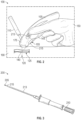
- FIG. 1 is a perspective view of an intravenous therapy system according to some embodiments of the present disclosure.
- the intravenous therapy system 100 described herein includes a housing 105, part of which, used to be held by a clinician or other healthcare provider during operation of the intravenous therapy system 100.
- the housing 105 may be formed out of any material that may house other components of the intravenous therapy system 100 as described herein.
- the intravenous therapy system 100 may include an ultrasound (US) probe 175 formed, in an embodiment, at a distal end of the housing 105 of the intravenous therapy system 100.
- the US probe 175 may be handheld.
- the US probe 175 may be any device that converts electrical signals from an electrical source into ultrasound waves and converts ultrasound waves received at the US probe 175 into electrical signals.
- the US probe 175 may receive an electrical signal and convert that electrical signal into ultrasound waves that are directed, either continuously or pulsed, to enter into a part of a patient's body. As the ultrasound waves enter the patient's body, those ultrasound waves may be reflected off of structures within the patient's body and reflected back to the US probe 175.
- the US probe 175 converts those ultrasound waves back into electrical signals. These electrical signals may be interpreted by a processor housed within the housing 105 of the intravenous therapy system 100 and used to form an image of the internal structures within the patient's body. In an embodiment presented herein, the electrical signals presented to the processor and used to form the images of the structures within the patient's body may be displayed at a video display device of the intravenous therapy system 100. In a specific application and during operation of the intravenous therapy system 100, the US probe 175 may be directed towards and in contact with, an arm of the patient in order to detect a position of a blood vessel 125 within the patient's arm.
- intravenous therapy system 100 also includes a video display device 110 communicatively coupled to the US probe 175 and the processor within the housing 105 among other components of the intravenous therapy system 100.
- the video display device 110 may receive input from the processor descriptive of the data received by the US probe 175. This input from the processor causes images of the structures within the patient's body to be presented on the video display device 110. The images presented may change as the position of the US probe 175 placed against the patient's body changes.
- the US probe 175 may include one or more US sensors, which may provide a transverse view of the blood vessel 125, a coronal or longitudinal view of a blood vessel 125, or another view based on a position of the US probe 175.
- the US sensors may be arranged in a two-dimensional array.
- the data from the US probe 175 sent to the processor may be data descriptive of the transverse view of the structures of the blood vessel 125 such as a vein within a patient's arm that are on a transverse plane 120 of the arm.
- the US probe 175 may be placed against any portion of the patient's body such as a leg in order to locate and access a blood vessel 125 with a VAD.
- the data from the US probe 175 sent to the processor may be data descriptive of a coronal view of the structures such as a vein within a patient's arm that are on a coronal plane 140 of the arm.
- the view along the coronal plane 140 may be the longitudinal view of a blood vessel of the patient that runs the length of the patient's arm.
- the video display device 110 may display either or both of the coronal planar view along the coronal plane 140 of the patient, the transverse planar view along the transverse plane 120 of the patient, or both.
- the housing 105 may also house the magnetic field detector (not shown), which may include one or more magnetic field sensors that are used to detect the presence of a metal.
- the magnetic field detector may detect any metal components of a VAD to be inserted into the patient.
- the magnetic field detector may detect the location of the metal components of the VAD relative to the US probe 175.
- the processor of the intravenous therapy system 100 may overlay positional location data related to the location and the projected position of the needle tip of the VAD onto any images presented on the video display device 110, such as the cross section of the vein.
- the video display device 110 may show the movement of the VAD passing into the blood vessel 125.
- the video display device 110 may show a trajectory point to which the VAD is going to intersect with the blood vessel 125.
- the intravenous therapy system 100 is a stand-alone system that may communicate, wirelessly with other networked computing systems.
- the housing 105 of the intravenous therapy system 100 may include a battery (not shown).
- the battery may include, in some embodiments, a smart battery system or be operatively coupled to a power management unit that tracks and provides power state data. This power state data may be stored with the instructions, parameters, and profiles to be used with the systems and methods disclosed herein.
- the intravenous therapy system 100 may be communicatively coupled to a processor (not shown).
- the intravenous therapy system 100 may be a stand-alone device that includes, within the housing 105, the processor.
- the intravenous therapy system 100 may be communicatively coupled to a processor exterior or remote to the housing 105 of the US probe 175.
- the processor may include the hardware architecture used to retrieve computer readable program code from a data storage device also housed within the housing 105 and execute that computer readable program code.
- the computer readable program code executed by the processor causes the intravenous therapy system 100 to perform the functions as described herein.
- the execution of the computer readable program code may cause the US probe 175 to receive electrical signals, convert those electrical signals into ultrasonic waves, cause those waves to be propagated into a patient's body, receive reflected ultrasonic waves, and provide data to the processor indicative of the structures present within the patient's body.
- the execution of the computer readable program code may cause a magnetic field detector to detect the presence and location of a portion of a VAD.
- the processor may also execute computer readable program code that causes the location data descriptive of the location and/or the projected path of the VAD to be overlaid onto ultrasonic images presented by the processor during operation of the US probe 175.
- the execution of the computer readable program code causes the intravenous therapy system 100 to operate such that a clinician or other HCP may accurately and precisely access a patient's blood vessel with little to no inaccurate placements of that VAD. Additionally, according to an embodiment of the present specification, the execution of the computer readable program code may allow the clinician or other HCP to assess the placement and indwelling of the VAD after the clinician or other HCP has successfully inserted the VAD into the patient's blood vessel.
- the housing 105 may include a VAD chassis 145.
- the VAD chassis 145 may be formed into a portion of the housing 105 that is closest to the patient's body.
- a VAD within the VAD chassis 145 may be automatically advanced in order to allow for the automatic insertion of the VAD into the patient's body.
- the VAD chassis 145 may be communicatively coupled to the processor so as to receive data descriptive of a trajectory of the VAD placed within the VAD chassis 145. The data is descriptive of the direction the VAD is to take in order to cause the VAD to intersect with a blood vessel within the patient's body.
- the US probe 175 and magnetic field detectors may provide data on a closed-loop feedback in order to direct the VAD into the patient's blood vessel as the VAD engages the patient's skin and the VAD is directed through the patient's body.
- the VAD chassis 145 may include a VAD advancement system that includes a motor, which may include a linear motor, a rotational motor, or any other suitable type of motor.
- the VAD advancement system may receive signals from the processor as described herein in order to advance the VAD into the patient's body using the motor.
- the motor may be a linear motor that produces a linear force along its length. This may allow the motor to pass the VAD loaded into the VAD chassis 145 away from the housing 105 of the intravenous therapy system 100 and into the body of the patient.
- the motor may also allow for the tilt movement, the rotation movement, and the yaw movement of the VAD during insertion.
- the linear, tilt, rotational, and yaw adjustments of the direction of the VAD allows for the VAD to intersect with the blood vessel of the patient in situations where the intravenous therapy system 100 is moved, either deliberately or accidentally, along the surface of the patient's body.
- the intravenous therapy system 100 may include an audio feedback device, a haptic feedback device, visual feedback, or a combination thereof, in order to indicate when the VAD being inserted into the blood vessel within the patient's body is determined to be on an intersecting trajectory into a blood vessel of the patient.
- the intravenous therapy system 100 may include another audio feedback device, another haptic feedback device, another visual feedback, or a combination thereof, in order to indicate if the VAD being inserted into the blood vessel within the patient's body is determined to not be on an intersecting trajectory into a blood vessel of the patient.
- the audio feedback device, a haptic feedback device, visual feedback, or a combination thereof may indicate to a clinician or other HCP when the VAD is aligned to intersect or misaligned so as to not be able to intersect with the patient's blood vessel and may indicate how to properly orient the intravenous therapy system 100 so as to allow for that intersection to occur.
- the video display device 110 may visually indicate that the VAD is not on a trajectory to intersect with the patient's blood vessel and may provide visual indications as to how to orient the intravenous therapy system 100 on the patient's body using x-, y-, and z-coordinate information.
- An audio signal produced by a speaker of the intravenous therapy system 100 may audibly provide feedback indicative of such a misalignment.
- a haptic feedback device such as a tumbler may be used to indicate when the VAD is no longer on a trajectory that will cause the VAD to intersect with the patient's blood vessel based on movement of the haptic feedback device, the US probe 175, or the patient.
- the intravenous therapy system 100 may include a VAD recommendation module (not shown).
- the VAD recommendation module may provide an audible or visual indicator that provides a suggestion as to which type of VAD to use in order to access the patient's blood vessel.
- An audible VAD recommendation may be presented via a speaker housed within the housing 105 of the intravenous therapy system 100.
- a visual VAD recommendation may be provided to the clinician or other HCP via the video display device 110. In any of these examples, the clinician or other HCP may be allowed to provide data descriptive of the purpose of the VAD prior to the VAD recommendation module providing the recommendation.
- Such data may indicate whether the purpose of the VAD is to retrieve a blood sample or whether the purpose of the VAD is to provide an infusing fluid such as a saline solution, a medicament, and/or a parenteral nutrition into the patient's bloodstream.
- the length of time the VAD is to remain in the patient's blood vessel may also be input by the clinician or other HCP in order for the VAD recommendation module to provide a more accurate VAD recommendation.
- the VAD recommendation module may be computer readable program code stored on a memory device, data storage device, or other device used to store computer readable program code.
- the computer readable program code in an embodiment may be accessed by the processor in order to execute that computer readable program code. The execution of that computer readable program code may bring about the assessment of and presentation to the clinician or other HCP of the VAD recommendation.
- the VAD recommendation module may be an application specific integrated circuit (ASIC). In this embodiment, the processor may access the ASIC in order to bring about the assessment of and presentation to the clinician or other HCP of the VAD recommendation.
- ASIC application specific integrated circuit
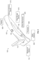
- FIG. 2 is a side view of an intravenous therapy system 100 interfacing with a patient's arm 190 according to some embodiments of the present disclosure.
- the intravenous therapy system 100 shows that the US probe 175 is interfacing with the patient's arm 190.
- the intravenous therapy system 100 is being held by the hand 150 of the clinician or other HCP.
- the clinician or other HCP uses a single hand 150 to hold the intravenous therapy system 100.
- the VAD chassis 145 may not be included and instead the clinician or other HCP, after receiving a VAD recommendation from the VAD recommendation module, use a second hand to place and insert the VAD at and into the patient's arm 190.
- the clinician or other HCP may situate the intravenous therapy system 100 and handheld VAD while using the video display device 110 to orient the VAD sufficiently and, based on the data presented on the video display device 110, direct the VAD into the patient's blood vessel.
- This view may present to the clinician or other HCP a "cross-sectional" view of the blood vessel 125 so that the clinician or other HCP may assess whether that blood vessel 125 or some other blood vessel 125 is to be accessed by the VAD.
- the transverse plane 120 may have a length 135 and a width 130.
- the video display device 110 may present a view of the blood vessel 125 on a coronal plane 140. This view may present to the clinician or other HCP a longitudinal view of the blood vessel 125 as the blood vessel 125 runs along the long axis of the patient's arm 190.
- the video display device 110 may present or be capable of presenting both the transverse plane 120 and coronal plane 140 as detected by the US probe 175.
- the clinician or other HCP may hold the intravenous therapy system 100 with one hand 150 and, with the opposite hand, orient and move a VAD towards and into the patient's arm 190.
- the clinician or other HCP may more accurately view the trajectory 155 of the VAD as the clinician or other HCP attempts to access the blood vessel 125.
- the clinician or other HCP may be provided with real-time data descriptive of the VAD relative to the blood vessel 125 using the data presented on the video display device 110 from the US probe 175 and magnetic field detector. This allows the clinician or other HCP to more accurately and precisely access the blood vessel 125 with little to no additional trauma to the patient's body. This increases the efficiency of VAD placements by the clinician or other HCP resulting in better healthcare to the patient.
- the blood vessel 125 may be an artery into which, for other medical reasons, the saline solution, a medicament, and/or a parenteral nutrition may be introduced.
- the US probe 175 may detect the movement of blood within the blood vessel 125 and determine whether the blood vessel 125 is a vein or artery.
- a clinician or other HCP may input to the intravenous therapy system 100 an indication that a vein is to be accessed.
- the US probe 175 may provide data descriptive of a vein to be accessed.
- the processor may cause the vein to be visually highlighted on the video display device 110 by, for example, drawing a line or other indicator around a transverse plane 120 view of the vein.
- the video display device 110 may be a touchscreen video display device 110 that allows a user to determine which blood vessel 125 is to be accessed by inputting on the screen of the video display device 110 a line or other indicator descriptive of a target blood vessel 125.
- the processor of the intravenous therapy system 100 may use the line or other indicator descriptive of a target blood vessel 125 to direct the insertion of the VAD by either appropriately actuating the motor of the VAD advancement system or directing the clinician or other HCP on how to adjust the trajectory 155 of the VAD during insertion.
- the housing 105 of the intravenous therapy system 100 may include a battery (not shown).
- the battery may include, in some embodiments, a smart battery system or be operatively coupled to a power management unit that tracks and provides power state data. This power state data may be stored with the instructions, parameters, and profiles to be used with the systems and methods disclosed herein.
- the intravenous therapy system 100 may include a network interface device that communicatively couple the intravenous therapy system 100 to a computer network.
- the intravenous therapy system 100 may be communicatively coupled to an electronic health record (EHR) database.
- the EHR database may be a database that maintains patient-specific health care records.
- the intravenous therapy system 100 may relay the use of a VAD on the patient as well as a record (either video or still images) of the placement of the VAD and the ultrasound data received at the US probe 175. This record may be maintained in order to create a relatively more robust health care record for a given patient.
- the intravenous therapy system 100 may be communicatively coupled to the EHR system or other computing device via a data and power cable.
- the data and power cable may be used when the intravenous therapy system 100 does not include a network interface and/or when the intravenous therapy system 100 does not include its own power source such as the battery described herein.
- the communication to the EHR system may allow for further communication to other computing devices of a network of computing devices.
- the example VAD 200 presented in Figure 3 includes a distal end 205 and a proximate end 210.
- the VAD 200 may include a needle 215 that is made of a metallic material that is capable of being magnetized.
- the VAD 200 may include a catheter 213, which may include a peripheral intravenous catheter, a midline catheter, or a peripherally inserted central catheter.
- the needle 215 may be hollow so as to be able to pass a blood sample, saline solution, a medicament, and/or a parenteral nutrition therethrough.
- the needle 215 may be beveled to create a point or sharp so as to more easily pass through the skin and body tissues of the patient's body while accessing the blood vessel as described herein.
- the VAD 200 may include any other elements that may fit a particular function during the blood sampling or blood infusion processes.
- the VAD 200 may include a plastic coupling device used to couple the VAD 200 to a reservoir of saline solution, a medicament, and/or a parenteral nutrition or to a blood sampling vile.
- the intravenous therapy system may implement the use of any type of VAD 200, the specific details of the VAD 200 may vary from use to use. However, the present specification contemplates the use of any VAD 200 that is configured for insertion into the body of the patient.
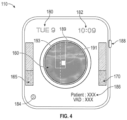
- Figure 4 is a graphical view of a video display device 110 according to some embodiments of the present disclosure.
- the video display device 110 receives data descriptive of the structures internal to a patient's body and, specifically, a blood vessel.
- the data is received by the processor from the US probe 175 and magnetic field detector and used to form the transverse plane 120 and coronal plane 140 images of the structures within the patient's body as well as calculate projection of the trajectory of the needle, such as, for example, the needle 215, based on the position of the needle tip relative to the US probe 175 and known geometries of the particular VAD (gauge, length, catheter brand, etc.) being used.
- VAD gauge, length, catheter brand, etc.
- the image presented in Figure 4 is a transverse plane 120 image 160 of a blood vessel within the patient.
- the video display device 110 may include a number of input buttons 188.
- actuation of the input buttons 188 may switch the view presented to the user.
- a dimensional reference indicator may also be included on the video display device 110 to allow a clinician to measure or have a reference for estimating a size of the patient's anatomy (such as vein diameter or vein depth).
- Figure 4 illustrates a projected path 189 of the needle, according to some embodiments.
- Figure 4 also illustrates a projected position 191 of where the needle tip will intersect a plane of the image 160 based on a trajectory 193 or path of movement of the needle.
- the projected position 191 In response to the projected position 191 being centered or properly aligned with respect to the blood vessel 125, conditions may be appropriate for advancement of the VAD (manually by the clinician or automatically as discussed herein).
- the video display device 110 may present to the user any data in additional to the transverse plane 120 and coronal plane 140 images 160.
- the video display device 110 may include the current date 180 and time 182 the intravenous therapy system is being used.
- the date 180 and time 182 may be used during the recording of the ultrasound and VAD insertion at the EHS described herein. This may be used to accurately date and document the procedure conducted by the clinician or other HCP.
- the video display device 110 may display a current ultrasound resolution 184 being viewed on the image 160.
- the input buttons 188 may be used to adjust the resolution of the image 160 so that a clinician or other HCP may see further detail of a blood vessel being presented.
- the video display device 110 may display patient and VAD information 186.
- the patient information may include the name of the patient, an assigned number related to the patient and the patient's EHR, as well as medically relevant medical data related to the patient such as blood vessel geometry, a date of birth, weight, current blood pressure, current pulse, among other data.
- the VAD information may include data descriptive of the type of VAD being used by the clinician or other HCP, the name or identity of the clinician or HCP, and recommended to be used by the VAD recommendation module, among other data.
- the video display device 110 may further include a number of VAD trajectory indicators 165 and 170.
- a first VAD trajectory indicator 165 may be used to indicate a depth within the patient's body the VAD is at.
- the first VAD trajectory indicator 165 may be color coded to indicate whether the depth of the VAD as it passes through the patient's body is in line with a processor-calculated trajectory. If the VAD is not at the correct depth at any given time during insertion of the VAD, the first VAD trajectory indicator 165 may visually indicate an improper trajectory by, for example, changing colors.
- the visual indication of a wrong trajectory may be accompanied with, in some examples, an audible warning from a speaker, a haptic feedback warning from a haptic device within the intravenous therapy system, or a combination of any of these three warning devices.
- a clinician or other HCP may accurately adjust the trajectory of the VAD, or intravenous therapy system based on the trajectory the VAD is to follow in order to intersect with a detected blood vessel.
- a second VAD trajectory indicator 170 may be used to indicate x-and y-coordinates within the patient's body the VAD is at.
- the second VAD trajectory indicator 170 may be color coded to indicate whether the placement of the VAD as it passes through the patient's body is in line with a processor-calculated trajectory.
- the second VAD trajectory indicator 170 may indicate how far along the projected path 189 the needle tip is and a distance of the needle tip from the targeted vein. If the VAD is not at the correct x- and y-coordinate at any given time during insertion of the VAD, the second VAD trajectory indicator 170 may visually indicate an improper trajectory by, for example, changing colors.
- the visual indication of a wrong trajectory may be accompanied with, in some examples, an audible warning from a speaker, a haptic feedback warning from a haptic device within the intravenous therapy system, or a combination of any of these three warning devices.
- a clinician or other HCP may accurately adjust the trajectory of the VAD, or intravenous therapy system based on the trajectory the VAD is to follow in order to intersect with a detected blood vessel.
- the video display device 110 may include a touchscreen layer.
- the touchscreen layer may allow a clinician or other HCP to provide input to the intravenous therapy system.
- An example of this input may include blood vessel indication data.
- the clinician or other HCP upon seeing a blood vessel such as a vein presented on the image 160 of the internal structures of the patient's body, may circle or otherwise indicate where the VAD is to intersect with the blood vessel.
- This indication along with the data received by the processor of the intravenous therapy system from the US probe and magnetic field detector, may be used to calculate the trajectory of the VAD by the processor.
- the trajectory may be used during automatic insertion of the VAD by a VAD advancement system or manual insertion of the VAD by a clinician or other HCP.
- the intravenous therapy system may be moved by the clinician or other HCP during insertion of the VAD.
- the video display device 110 may also include any other indicator on the screen that may indicate to the clinician or other HCP to keep the target blood vessel on the screen by readjusting the intravenous therapy system relative to the patient's body.
- Figure 5A is a graphical view of a blood vessel 125 along a transverse plane 120 according to an embodiment of the present disclosure.
- the embodiment shown in Figure 5A indicates a length 135 and width 130 that the image encompasses.
- the length 135 and width 130 may vary depending on a selected resolution as well as the ultrasonic capabilities of the US probe described herein.
- the clinician or other HCP may use the first of the VAD advancement buttons 915 to follow a determined trajectory of the VAD while also receiving input from the video display device 910 as to whether the clinician or other HCP is directing the VAD along the z-direction to follow the trajectory.
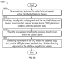
- the method 1000 may also include providing, visually with a display device of the handheld ultrasound device, recommended VAD placement locations within the patient's body at block 1010.
- the data received by the processor may be used to detect the presence of a blood vessel such as a vein within the patient's body.
- the processor may determine a location of a blood vessel based on a detection of blood flow from the ultrasound device, the differences in hues of colors presented on the display device of the interior structures of the patient's body, the detection of movement of the exterior walls of the blood vessel, among other types of indicia.
- the method 1000 may further include, at block 1015, providing a suggested VAD type to access a blood vessel within the patient's body.
- the type of VAD recommended by the in an example a VAD recommendation module, may be dependent on a number of factors including the location of the blood vessel to be accessed, the type, condition and anatomy of the blood vessel being accessed, the purpose of the VAD (e.g., blood sampling or infusion therapies), and patient characteristics, among other factors.
- the type of VAD recommended may include specifics about a VAD such as length, gauge, and material, among other features of a VAD.
- the suggested VAD type may be provided on a video display device after execution of a VAD recommendation module by the processor of the intravenous therapy system.
- a clinician or other HCP may review the VAD recommendation, locate the recommend VAD, and load the VAD into a VAD chassis of the intravenous therapy system for later insertion into the patient.
- the method 1000 may further include monitoring movement of the VAD within the patient's body and provide VAD placement feedback to a clinician directing alignment of the VAD to a target blood vessel at block 1020.
- the intravenous therapy system may include both an ultrasound (US) device and a magnetic field detector.
- the data received from the US device and the magnetic field detector may be provided to the processor in order to determine the relative location of the tip of the VAD to the VAD placement location determined previously by the processor.
- the processor may overlay an image of the VAD onto US images presented on the video display device so that a clinician or other HCP may see the trajectory of the VAD as it passes through the patient's body and into the blood vessel.
- the movement of the VAD may be accomplished by the clinician or other HCP.
- the movement of the VAD may be automatic via use of one or more linear motors formed within a VAD chassis.
- the clinician or other HCP may select between a manual VAD insertion mode or an automatic VAD insertion mode.
- the clinician may be provided with a VAD recommendation and initiate a manual insertion of the VAD as described herein.
- an automatic VAD insertion mode the clinician may be provided with a VAD recommendation, insert the VAD into the VAD chassis, and initiate the automatic insertion of the VAD into the patient's body as described herein.
- the processor may pause the automatic insertion of the VAD if and when it is detected that the VAD is not following a calculated trajectory.
- the clinician may initiate a manual override for any of a number of reasons including, but not limited to, clinician error and nonessential use of the VAD.
- FIG 11 is a flowchart depicting a method 1100 of manufacturing an intravenous therapy system according to some embodiments of the present disclosure.
- the method 1100 may include forming, at block 1105, an ultrasound (US) probe in a housing to form a handheld US device.
- the housing may be made of a plastic or other non-metallic material so as to avoid interference with the US probe and a magnetic field detector within the intravenous therapy system.
- the US probe may be any device that converts electrical signals from an electrical source into ultrasound waves and converts ultrasound waves received at the US probe into electrical signals.
- the US probe may receive an electrical signal and convert that electrical signal into ultrasound waves that are directed, either continuously or pulsed, to enter into a part of a patient's body.
- the method 1100 may further include forming a magnetic field detector within the handheld ultrasound device at block 1110.
- the magnetic field detector may detect any metal components of a VAD to be inserted into the patient.
- the magnetic field detector may detect the location of the metal components of the VAD relative to the US probe.
- the processor of the intravenous therapy system may overlay positional location data related to the location of the metal components of the VAD onto any images presented on a video display device.
- the video display device displays a coronal plane of the patient's arm
- the video display device may show the movement of the VAD passing into the blood vessel.
- the video display device displays a transverse plane of the patient's arm
- the video display device may show a trajectory point to which the VAD is going to intersect with the blood vessel.
- the method 1100 may include, at block 1115, includes forming a vascular access device (VAD) chassis within the handheld US device to maintain a VAD therein.
- VAD vascular access device
- the VAD chassis may hold any type of VAD therein during operation of the intravenous therapy system.
- the method 1100 may also include, at block 1120, forming a processor within the handheld US device to receive data from the ultrasound probe and magnetic field detector.
- the processor may be communicatively coupled to the US probe, the magnetic field detector, and a linear motor, among other devices housed within the housing of the ultrasound device described herein.
- the data received by the processor from the magnetic field detector and US probe may be used to display the movement of the VAD through the patient's body on the video display device.
- the method 1100 may further include forming a display device on the handheld ultrasound device to receive data from the processor and present an ultrasound image of a blood vessel within a patient's body at block 1125.
- the data produced at the video display device may be used by the clinician or other HCP to manually or automatically direct the VAD into the patient's body. Because the video display device is formed into the housing of the intravenous therapy system, the clinician or other HCP may keep their line of sight at the location where the VAD is being inserted into the patient's body so that the clinician or other HCP may, in real time, monitor the advancement of the VAD into and through the patient's body. In other embodiments, the video display device may be used to assess proper initial placement of the VAD, and any provide subsequent indwelling assessments of the VAD within the patient's body.
- the method 1100 may also include, at block 1130, forming a linear motor within the handheld ultrasound to advance the VAD from the VAD chassis in order to cause the VAD to access a blood vessel within the patient's body.
- a linear motor within the handheld ultrasound to advance the VAD from the VAD chassis in order to cause the VAD to access a blood vessel within the patient's body.
- a plurality of linear and/or rotational motors may be used to align the VAD along a determined trajectory the VAD is to follow so that the VAD may intersect with an identified blood vessel within the patient's body.
- these motors may control the VAD so as to orient or rotate the VAD in any direction along any x-, y-, or z-coordinate plane.
- the processor may have created a trajectory path through the patient's body leading from a distal tip of the VAD to a predetermined location within a blood vessel.
- the processor through actuation of a VAD advancement button by a clinician or other HCP, may direct the linear motors to pass the distal tip of the VAD along this path and into the blood vessel of the patient.
- the clinician may manually pass the VAD through the patient's body based on the created trajectory with the processor providing visual, haptic, or audible alerts to the clinician or other HCP when the trajectory is not being followed. Consequently, the method 1100 may further include the forming of a speaker and/or haptic feedback device into the housing of the intravenous therapy system.
- the method 1100 may further include forming a battery and data storage device within the housing of the intravenous therapy system.
- the battery may provide power to the different devices within the intravenous therapy system while the data storage device maintains data and computer readable program code to be accessed by the processor during operation of the intravenous therapy system.
- the embodiments described herein provide for an intravenous therapy system that includes a visual display device used to direct a VAD into the body of a patient in order to properly and easily access a blood vessel therein.
- a visual display device used to direct a VAD into the body of a patient in order to properly and easily access a blood vessel therein.
- These embodiments implement an US device that detects the internal structure of the patient's body and displays images of those internal structures, such as blood vessels, on a display device physically and operatively coupled to the housing of the US device.
- a clinician or other health care provider may detect where the distal tip of the VAD is relative to a target location within the blood vessel via use of a magnetic field detector housed within the US device.
- the metal tip of the VAD may be overlaid onto the US images presented at the video display device so that the user may more easily recognize how to orient the VAD during insertion. Additionally, a trajectory may be calculated by a processor of the US device such that the manual insertion of the VAD may be monitored and alters may be presented to the clinician or other HCP if and when the current trajectory of the VAD is off target from the calculated trajectory. This allows for accurate and precise placement of the VAD into the patient's body resulting in less damage the tissue of the patient's body and less anxiety experienced by the patient.
- the VAD may be more accurate inserted into the patient's body through the use of a VAD chassis and linear motors.
- the VAD chassis may be used to hold a VAD that has been recommended to the clinician or other HCP after the processor has received data from the US device as well as other data related to the patient and purpose of the VAD.
- the intravenous therapy system may actuate any number of linear motors that control the alignment of the VAD to a trajectory calculated by the processor.
- the clinician or other HCP may maintain the intravenous therapy system at a location on the patient's arm while the automatic VAD placement systems place the VAD into and through the patient's body along the recommended trajectory.
- an alert system may indicate to the clinician that the intravenous therapy system is to be returned to the appropriate position so that the VAD may be advanced appropriately.
- the video display device presents real-time images of the internal structures of the patient's body as well as the location of the VAD within the body, a clinician may better assess the trajectory of the VAD at any time.
- the intravenous therapy system provides a continual feedback loop so as to more accurately and precisely locate the VAD within a blood vessel.
- a video recording may be generated and saved on a memory device interior or remote to the intravenous therapy system so that an EHR may be maintained descriptive of the VAD being used, the data and time of the insertion of the VAD, any patient data, and intended uses of the VAD. This may create a more robust record of care related to any given patient thereby increasing the efficiency of any medical treatment provided.
- These records may be maintained on a central database when the intravenous therapy system transfers the data to an information handling system or other computing device via a wired or wireless connection.
- the embodiments of the present application may be combined.
- the embodiments of Figures 1-9 may be arranged to fit specific uses based on the type of action being conducted.
- the intravenous therapy system may indicate, via the indicator system, a location of the artery while avoiding any veins. This may allow for the introduction of certain medicaments into a specific location in the patient's body without concern for that medicament being distributed throughout the patient's body.
- arteries may be avoided when a vein is to be accessed.
Landscapes
- Health & Medical Sciences (AREA)
- Life Sciences & Earth Sciences (AREA)
- Engineering & Computer Science (AREA)
- Surgery (AREA)
- Heart & Thoracic Surgery (AREA)
- General Health & Medical Sciences (AREA)
- Animal Behavior & Ethology (AREA)
- Veterinary Medicine (AREA)
- Biomedical Technology (AREA)
- Public Health (AREA)
- Molecular Biology (AREA)
- Medical Informatics (AREA)
- Nuclear Medicine, Radiotherapy & Molecular Imaging (AREA)
- Pathology (AREA)
- Biophysics (AREA)
- Physics & Mathematics (AREA)
- Radiology & Medical Imaging (AREA)
- Vascular Medicine (AREA)
- Anesthesiology (AREA)
- Hematology (AREA)
- Pulmonology (AREA)
- Robotics (AREA)
- Gastroenterology & Hepatology (AREA)
- Gynecology & Obstetrics (AREA)
- Oral & Maxillofacial Surgery (AREA)
- Dermatology (AREA)
- Human Computer Interaction (AREA)
- Ultra Sonic Daignosis Equipment (AREA)
- Infusion, Injection, And Reservoir Apparatuses (AREA)
Claims (8)
- Blutgefäßdetektionssystem (610), das aufweist:
eine handgehaltene Blutgefäßdetektionsvorrichtung, die aufweist:eine Ultraschallsonde (175) zum Detektieren von Blutgefäßen innerhalb eines Patientenkörpers,eine Anzeigevorrichtung (110) zum Bereitstellen einer optischen Anzeige der Blutgefäße innerhalb des Patientenkörpers;ein Gestell einer Gefäßzugangsvorrichtung (VAD) zum Halten einer VAD; undeinen Linearmotor (825) zum automatischen Vorbewegen der VAD in den Patientenkörper,dadurch gekennzeichnet, dassdas VAD-Gestell (145) in einem Gehäuse (105) der handgehaltenen Blutgefäßdetektionsvorrichtung vorgesehen ist; undder Linearmotor dazu ausgebildet ist, eine Kippbewegung, eine Rotationsbewegung, und eine Gierbewegung der VAD beim Einsetzen zu ermöglichen. - Blutgefäßdetektionssystem nach Anspruch 1, das ferner ein Augmented-Reality-Headset aufweist, um eine erweiterte Ansicht der Blutgefäße innerhalb des Patientenkörpers, die von der Ultraschallsonde detektiert werden, und eine Platzierung der VAD relativ zu dem Patientenkörper an einen Arzt zu projizieren.
- Blutgefäßdetektionssystem nach Anspruch 1, das ferner ein elektronisches Patientenakten-(EHR)-System aufweist, das kommunikativ mit der handgehaltenen Blutgefäßdetektionsvorrichtung gekoppelt ist, um Bilder einer Abbildung der Blutgefäße des Patienten und der Platzierung der VAD innerhalb des Patientenkörpers aufzunehmen.
- Blutgefäßdetektionssystem nach Anspruch 1, wobei der Linearmotor einen Axialmotor und einen Drehmotor aufweist, um eine axiale und rotative Richtung der VAD zu ändern.
- Blutgefäßdetektionssystem nach Anspruch 1, das ferner eine Stromversorgung aufweist, die mit der handgehaltenen Ultraschallvorrichtung elektrisch gekoppelt ist.
- Blutgefäßdetektionssystem nach Anspruch 1, das ferner eine Linearmotor-Betätigungstaste an der Ultraschallsonde aufweist.
- Blutgefäßdetektionssystem nach Anspruch 1, das ferner eine Analysemodul aufweist für Folgendes:Detektieren der Blutgefäße innerhalb des Patientenkörpers;Definieren der Geometrie der Blutgefäße;Erstellen eines Feedback-Fence um die definierte Geometrie der Blutgefäße; undBereitstellen von Feedback, über eine Feedback-Vorrichtung, das angibt, wenn eine Trajektorie der VAD in den und innerhalb des Patientenkörpers so projiziert wird, dass sie innerhalb eines Blutgefäßes positioniert ist, oder nicht so projiziert wird, dass sie innerhalb eines Blutgefäßes positioniert ist.
- Blutgefäßdetektionssystem nach Anspruch 7, wobei der Feedback-Fence durch die Ausführung eines Algorithmus oder einer Eingabe definiert wird, die an der Anzeigevorrichtung erhalten wird, welche die Geometrie der Blutgefäße anzeigt.
Applications Claiming Priority (4)
| Application Number | Priority Date | Filing Date | Title |
|---|---|---|---|
| US201962794440P | 2019-01-18 | 2019-01-18 | |
| US16/742,676 US12178982B2 (en) | 2019-01-18 | 2020-01-14 | Intravenous therapy system for blood vessel detection and vascular access device placement |
| PCT/US2020/013870 WO2020150465A2 (en) | 2019-01-18 | 2020-01-16 | Intravenous therapy system for blood vessel detection and vascular access device placement |
| EP20705841.3A EP3911220B1 (de) | 2019-01-18 | 2020-01-16 | System zur intravenösen therapie zur detektion von blutgefässen und platzierung von gefässzugangsvorrichtungen |
Related Parent Applications (2)
| Application Number | Title | Priority Date | Filing Date |
|---|---|---|---|
| EP20705841.3A Division EP3911220B1 (de) | 2019-01-18 | 2020-01-16 | System zur intravenösen therapie zur detektion von blutgefässen und platzierung von gefässzugangsvorrichtungen |
| EP20705841.3A Division-Into EP3911220B1 (de) | 2019-01-18 | 2020-01-16 | System zur intravenösen therapie zur detektion von blutgefässen und platzierung von gefässzugangsvorrichtungen |
Publications (4)
| Publication Number | Publication Date |
|---|---|
| EP4265194A2 EP4265194A2 (de) | 2023-10-25 |
| EP4265194A3 EP4265194A3 (de) | 2023-12-27 |
| EP4265194B1 true EP4265194B1 (de) | 2025-04-02 |
| EP4265194C0 EP4265194C0 (de) | 2025-04-02 |
Family
ID=71609618
Family Applications (2)
| Application Number | Title | Priority Date | Filing Date |
|---|---|---|---|
| EP23196490.9A Active EP4265194B1 (de) | 2019-01-18 | 2020-01-16 | System zur intravenösen therapie zur detektion von blutgefässen und platzierung von gefässzugangsvorrichtungen |
| EP20705841.3A Active EP3911220B1 (de) | 2019-01-18 | 2020-01-16 | System zur intravenösen therapie zur detektion von blutgefässen und platzierung von gefässzugangsvorrichtungen |
Family Applications After (1)
| Application Number | Title | Priority Date | Filing Date |
|---|---|---|---|
| EP20705841.3A Active EP3911220B1 (de) | 2019-01-18 | 2020-01-16 | System zur intravenösen therapie zur detektion von blutgefässen und platzierung von gefässzugangsvorrichtungen |
Country Status (13)
| Country | Link |
|---|---|
| US (1) | US12178982B2 (de) |
| EP (2) | EP4265194B1 (de) |
| JP (1) | JP7422773B2 (de) |
| KR (1) | KR102833596B1 (de) |
| CN (1) | CN212090424U (de) |
| AU (1) | AU2020209211B2 (de) |
| BR (1) | BR112021014114A2 (de) |
| CA (1) | CA3126025A1 (de) |
| ES (1) | ES2969161T3 (de) |
| MX (1) | MX2021008237A (de) |
| MY (1) | MY208201A (de) |
| SG (1) | SG11202107457VA (de) |
| WO (1) | WO2020150465A2 (de) |
Families Citing this family (40)
| Publication number | Priority date | Publication date | Assignee | Title |
|---|---|---|---|---|
| CA3152545A1 (en) | 2019-09-20 | 2021-03-25 | Bard Access Systems, Inc. | Automatic vessel detection tools and methods |
| US12447310B2 (en) * | 2020-06-03 | 2025-10-21 | Atif Hameed Farooqi | Catheter guide and method for operating the same |
| CN113952031B (zh) | 2020-07-21 | 2025-10-17 | 巴德阿克塞斯系统股份有限公司 | 磁跟踪超声探头及生成其3d可视化的系统、方法和设备 |
| US12186070B2 (en) | 2020-08-04 | 2025-01-07 | Bard Access Systems, Inc. | Systemized and method for optimized medical component insertion monitoring and imaging enhancement |
| CN217907826U (zh) * | 2020-08-10 | 2022-11-29 | 巴德阿克塞斯系统股份有限公司 | 医学分析系统 |
| WO2022055887A1 (en) | 2020-09-08 | 2022-03-17 | Bard Access Systems, Inc. | Dynamically adjusting ultrasound-imaging systems and methods thereof |
| CN216257185U (zh) | 2020-09-10 | 2022-04-12 | 巴德阿克塞斯系统股份有限公司 | 超声探测器和超声系统 |
| CN114190975A (zh) | 2020-09-18 | 2022-03-18 | 巴德阿克塞斯系统股份有限公司 | 具有指示器远程控制能力的超声探测器 |
| US11925505B2 (en) | 2020-09-25 | 2024-03-12 | Bard Access Systems, Inc. | Minimum catheter length tool |
| US12137987B2 (en) | 2020-10-02 | 2024-11-12 | Bard Access Systems, Inc. | Ultrasound systems and methods for sustained spatial attention |
| CN121221162A (zh) | 2020-10-15 | 2025-12-30 | 巴德阿克塞斯系统股份有限公司 | 超声成像系统和使用其创建目标区域的三维超声图像的方法 |
| EP4247267A1 (de) * | 2020-11-24 | 2023-09-27 | Bard Access Systems, Inc. | Ultraschallsystem mit ziel- und medizinischem instrumentenbewusstsein |
| WO2022119853A1 (en) | 2020-12-01 | 2022-06-09 | Bard Access Systems, Inc. | Ultrasound probe with target tracking capability |
| US12165315B2 (en) | 2020-12-01 | 2024-12-10 | Bard Access Systems, Inc. | Ultrasound system with pressure and flow determination capability |
| JP2024036700A (ja) * | 2021-01-18 | 2024-03-18 | テルモ株式会社 | 血管位置表示器 |
| EP4301237A1 (de) | 2021-03-05 | 2024-01-10 | Bard Access Systems, Inc. | Systeme und verfahren zur ultraschall- und bioimpedanzbasierten führung von medizinischen vorrichtungen |
| WO2022212414A1 (en) | 2021-03-29 | 2022-10-06 | Bard Access Systems, Inc. | System and method for a vessel assessment tool |
| CN217960146U (zh) | 2021-04-15 | 2022-12-06 | 巴德阿克塞斯系统股份有限公司 | 超声成像系统 |
| JP2024521977A (ja) * | 2021-04-19 | 2024-06-04 | ヴェインテク ピーティーワイ リミテッド | ポータブル超音波装置及び超音波撮像方法 |
| CN113317816A (zh) * | 2021-05-07 | 2021-08-31 | 武汉凯进医疗技术有限公司 | 支持实时状态显示的无线便携式掌上超声处理设备及方法 |
| US12575892B2 (en) | 2021-06-22 | 2026-03-17 | Bard Access Systems, Inc. | Ultrasound detection system |
| EP4415625B1 (de) | 2021-10-14 | 2026-04-01 | Bard Access Systems, Inc. | Faseroptische ultraschallsonde |
| EP4422507B1 (de) | 2021-11-03 | 2026-04-15 | Bard Access Systems, Inc. | Optimierte funktionalität durch interoperation von doppler- und bildbasierter gefässdifferenzierung |
| EP4426225A1 (de) | 2021-11-16 | 2024-09-11 | Bard Access Systems, Inc. | Ultraschallsonde mit integrierten datensammelverfahren |
| WO2023129636A1 (en) | 2021-12-29 | 2023-07-06 | Creare Llc | Penetrative medical access devices, and related methods and systems |
| US12514532B2 (en) | 2022-03-01 | 2026-01-06 | Bard Access Systems, Inc. | Ultrasound imaging system |
| US12514533B2 (en) | 2022-03-01 | 2026-01-06 | Bard Access Systems, Inc. | Ultrasound imaging system |
| CN116763338A (zh) | 2022-03-16 | 2023-09-19 | 巴德阿克塞斯系统股份有限公司 | 超声成像系统 |
| US12207967B2 (en) | 2022-04-20 | 2025-01-28 | Bard Access Systems, Inc. | Ultrasound imaging system |
| US20230380906A1 (en) * | 2022-05-26 | 2023-11-30 | Bard Access Systems, Inc. | Ultrasound Imaging Device with Automatic Adjusting Needle Guide |
| US12102481B2 (en) | 2022-06-03 | 2024-10-01 | Bard Access Systems, Inc. | Ultrasound probe with smart accessory |
| US20230404683A1 (en) * | 2022-06-15 | 2023-12-21 | Bard Access Systems, Inc. | Systems and Methods for Automatically Recommending a Medical Device for Vascular Access |
| US20240008894A1 (en) * | 2022-07-07 | 2024-01-11 | Bard Access Systems, Inc. | Systems and Methods for Automatic Determination of Needle Guides for Vascular Access |
| US12137989B2 (en) | 2022-07-08 | 2024-11-12 | Bard Access Systems, Inc. | Systems and methods for intelligent ultrasound probe guidance |
| US12564373B2 (en) | 2022-08-15 | 2026-03-03 | Bard Access Systems, Inc. | Spatially aware medical device configured for performance of insertion pathway approximation |
| JP2024060296A (ja) * | 2022-10-19 | 2024-05-02 | 富士フイルム株式会社 | 超音波診断装置および超音波診断装置の制御方法 |
| IT202200022212A1 (it) * | 2022-10-28 | 2024-04-28 | Bracco Imaging Spa | Cateterizzazione con inserimento ago e rilascio elemento funzionale automatici |
| US12213845B2 (en) | 2022-11-03 | 2025-02-04 | Resuscitation Innovations Llc | Ultrasound guided femoral artery access system (UFAAS) and method to enhance brain perfusion during neuroprotective CPR |
| WO2025207580A1 (en) * | 2024-03-29 | 2025-10-02 | Bard Access Systems, Inc. | Systems and methods for medical device tracking |
| US12491003B2 (en) * | 2024-04-19 | 2025-12-09 | Kalysto Labs, LLC | Systems and methods for ultrasonic guided needle insertion |
Family Cites Families (35)
| Publication number | Priority date | Publication date | Assignee | Title |
|---|---|---|---|---|
| US375394A (en) * | 1887-12-27 | Joseph steachan | ||
| JPS61215961A (ja) | 1986-03-18 | 1986-09-25 | Hitachi Medical Corp | 超音波断層装置 |
| BR9609484A (pt) * | 1995-07-16 | 1999-12-14 | Yoav Paltieli | Processo e aparelho para direcionamento à mão livre de uma agulha so sentido de um alvo localizado em um volume corpóreo e aparelho de agulha |
| US6068599A (en) | 1997-07-14 | 2000-05-30 | Matsushita Electric Industrial Co., Ltd. | Blood vessel puncturing device using ultrasound |
| US6755789B2 (en) | 2002-02-05 | 2004-06-29 | Inceptio Medical Technologies, Llc | Ultrasonic vascular imaging system and method of blood vessel cannulation |
| US20090118670A1 (en) | 2005-04-22 | 2009-05-07 | Sieglinde Neerken | Cannula inserting system |
| EP1888152A2 (de) | 2005-05-10 | 2008-02-20 | Koninklijke Philips Electronics N.V. | Kanüleneinführungssystem |
| US20080221396A1 (en) * | 2005-07-25 | 2008-09-11 | Becton Dickinson And Company | Method and System for Monitoring Medical Treatment |
| US8852111B2 (en) | 2005-09-02 | 2014-10-07 | Ultrasound Ventures, Llc | Ultrasound guidance system |
| DE102005045602B4 (de) * | 2005-09-23 | 2017-07-13 | Siemens Healthcare Gmbh | Verfahren zum Unterstützen eines interventionellen medizinischen Eingriffs |
| AU2009268341B2 (en) * | 2008-07-11 | 2014-08-21 | Houston Medical Robotics, Inc. | Methods and apparatus for introducing a medical device into the body of a patient |
| US20100016726A1 (en) * | 2008-07-18 | 2010-01-21 | Meier Joseph H | Handheld Imaging Device And Method For Manufacture Thereof |
| WO2010025336A1 (en) | 2008-08-29 | 2010-03-04 | Corindus Ltd. | Catheter simulation and assistance system |
| WO2011085135A1 (en) * | 2010-01-07 | 2011-07-14 | Verathon Inc. | Blood vessel access device, sysem, and method |
| US9033880B2 (en) | 2011-04-05 | 2015-05-19 | Houston Medical Robotics, Inc. | Robotic insertion systems and methods |
| LT2939601T (lt) | 2011-09-06 | 2019-02-25 | Ezono Ag | Magnetinis medicininis įrenginys |
| CN103028185B (zh) | 2011-09-30 | 2017-04-12 | Ge医疗系统环球技术有限公司 | 基于实时容积超声波的自动血管介入装置、系统、及方法 |
| WO2013075093A1 (en) | 2011-11-18 | 2013-05-23 | Verathon, Inc. | Neuro-vasculature access system and device |
| KR20130089037A (ko) | 2012-02-01 | 2013-08-09 | 삼성메디슨 주식회사 | 바늘 가이드 장치를 제어하는 방법 및 그를 위한 초음파 진단 장치 |
| CN109394216B (zh) | 2012-03-18 | 2021-11-02 | 特洛玛泰克解决方案私人有限公司 | 一种用于血管进入和治疗的设备和方法 |
| GB201303917D0 (en) | 2013-03-05 | 2013-04-17 | Ezono Ag | System for image guided procedure |
| EP2805677B1 (de) * | 2013-04-29 | 2020-04-29 | Samsung Medison Co., Ltd. | Diagnostische Ultraschallvorrichtung, Ultraschallsonde, Betriebsverfahren für diagnostische Ultraschallvorrichtung und Betriebsverfahren für Ultraschallsonde |
| JP6073743B2 (ja) | 2013-05-14 | 2017-02-01 | 東芝メディカルシステムズ株式会社 | 超音波診断装置及び画像処理プログラム |
| US9558405B2 (en) | 2015-01-16 | 2017-01-31 | Analogic Corporation | Imaging based instrument event tracking |
| US10136915B2 (en) | 2015-01-26 | 2018-11-27 | Loving Heart Medical Technology Inc. | Ultrasound needle guide apparatus |
| US20170080166A1 (en) | 2015-09-18 | 2017-03-23 | Actuated Medical, lnc. | Device and System for Insertion of Penetrating Member |
| US20170203053A1 (en) | 2016-01-19 | 2017-07-20 | Joseph Choate Burkett | Visual-Assisted Insertion Device |
| KR20170093422A (ko) | 2016-02-05 | 2017-08-16 | 길재소프트 주식회사 | 증강현실 영상을 지원하는 초음파 영상 진단 시스템 |
| US10786224B2 (en) * | 2016-04-21 | 2020-09-29 | Covidien Lp | Biopsy devices and methods of use thereof |
| US11116419B2 (en) | 2016-06-01 | 2021-09-14 | Becton, Dickinson And Company | Invasive medical devices including magnetic region and systems and methods |
| US10398514B2 (en) * | 2016-08-16 | 2019-09-03 | Insight Medical Systems, Inc. | Systems and methods for sensory augmentation in medical procedures |
| ES2940449T3 (es) | 2016-12-14 | 2023-05-08 | Bard Inc C R | Agujas para su uso con sistemas para guiar un instrumento médico |
| GB2562502A (en) | 2017-05-16 | 2018-11-21 | Medaphor Ltd | Visualisation system for needling |
| US20190374199A1 (en) * | 2018-06-07 | 2019-12-12 | Remington Medical, Inc. | Handheld Ultrasound Device and Replaceable Tips Therefor |
| US10603479B2 (en) * | 2018-08-28 | 2020-03-31 | Access For Life Inc. | Vascular access device and method |
-
2020
- 2020-01-14 US US16/742,676 patent/US12178982B2/en active Active
- 2020-01-16 SG SG11202107457VA patent/SG11202107457VA/en unknown
- 2020-01-16 EP EP23196490.9A patent/EP4265194B1/de active Active
- 2020-01-16 MX MX2021008237A patent/MX2021008237A/es unknown
- 2020-01-16 EP EP20705841.3A patent/EP3911220B1/de active Active
- 2020-01-16 KR KR1020217025804A patent/KR102833596B1/ko active Active
- 2020-01-16 CA CA3126025A patent/CA3126025A1/en active Pending
- 2020-01-16 MY MYPI2021004041A patent/MY208201A/en unknown
- 2020-01-16 WO PCT/US2020/013870 patent/WO2020150465A2/en not_active Ceased
- 2020-01-16 BR BR112021014114-6A patent/BR112021014114A2/pt unknown
- 2020-01-16 ES ES20705841T patent/ES2969161T3/es active Active
- 2020-01-16 JP JP2021541655A patent/JP7422773B2/ja active Active
- 2020-01-16 AU AU2020209211A patent/AU2020209211B2/en active Active
- 2020-01-20 CN CN202020125247.7U patent/CN212090424U/zh active Active
Also Published As
| Publication number | Publication date |
|---|---|
| ES2969161T3 (es) | 2024-05-16 |
| BR112021014114A2 (pt) | 2021-09-21 |
| CN212090424U (zh) | 2020-12-08 |
| EP4265194A2 (de) | 2023-10-25 |
| US20200230391A1 (en) | 2020-07-23 |
| JP7422773B2 (ja) | 2024-01-26 |
| KR102833596B1 (ko) | 2025-07-16 |
| AU2020209211A1 (en) | 2021-08-12 |
| EP3911220A2 (de) | 2021-11-24 |
| WO2020150465A2 (en) | 2020-07-23 |
| WO2020150465A3 (en) | 2020-08-27 |
| EP3911220C0 (de) | 2023-10-25 |
| SG11202107457VA (en) | 2021-08-30 |
| NZ778183A (en) | 2025-07-25 |
| EP3911220B1 (de) | 2023-10-25 |
| KR20210118422A (ko) | 2021-09-30 |
| US12178982B2 (en) | 2024-12-31 |
| JP2022523011A (ja) | 2022-04-21 |
| EP4265194C0 (de) | 2025-04-02 |
| CA3126025A1 (en) | 2020-07-23 |
| MY208201A (en) | 2025-04-23 |
| EP4265194A3 (de) | 2023-12-27 |
| AU2020209211B2 (en) | 2025-05-29 |
| MX2021008237A (es) | 2021-08-16 |
Similar Documents
| Publication | Publication Date | Title |
|---|---|---|
| EP4265194B1 (de) | System zur intravenösen therapie zur detektion von blutgefässen und platzierung von gefässzugangsvorrichtungen | |
| Leipheimer et al. | First-in-human evaluation of a hand-held automated venipuncture device for rapid venous blood draws | |
| US20250352167A1 (en) | Optimized Functionality Through Interoperation of Doppler and Image Based Vessel Differentiation | |
| CN113164117B (zh) | 经皮插管器械的超声引导对准与插入 | |
| EP4251063B1 (de) | Ultraschallsonde mit zielverfolgungsfähigkeit | |
| EP3815636A1 (de) | Ultraschallgeführte hilfsvorrichtung und system für nadel | |
| US20230132148A1 (en) | High Fidelity Doppler Ultrasound Using Vessel Detection For Relative Orientation | |
| US20210085282A1 (en) | Automatic Vessel Detection Tools and Methods | |
| US20130197355A1 (en) | Method of controlling needle guide apparatus, and ultrasound diagnostic apparatus using the same | |
| JP2022544625A (ja) | 可搬型の超音波誘導下カニューレ挿入のためのシステム及び方法 | |
| US20120172722A1 (en) | Ultrasound apparatus and graphical interface for procedural assistance | |
| CN219323439U (zh) | 超声成像系统和超声探测器装置 | |
| CN117224169A (zh) | 用于自动推荐用于脉管进入的医疗设备的系统和方法 | |
| US20240390605A1 (en) | Imaging system and method for integrated vascular access device indwell assessment and data integration | |
| US12539141B2 (en) | Penetrative medical access devices, and related methods and systems | |
| WO2023002933A1 (ja) | 血管穿刺装置および血管穿刺システム | |
| WO2020142338A1 (en) | Needle insertion into subcutaneous target | |
| CN207856026U (zh) | 一种静脉穿刺装置及系统 | |
| Leipheimer | Hand-held robotic device for venipuncture procedures | |
| US20240347151A1 (en) | Collecting and connecting vascular access data throughout the continuity of care | |
| WO2025151232A1 (en) | Vascular access device indwell assessment and documentation |
Legal Events
| Date | Code | Title | Description |
|---|---|---|---|
| PUAI | Public reference made under article 153(3) epc to a published international application that has entered the european phase |
Free format text: ORIGINAL CODE: 0009012 |
|
| STAA | Information on the status of an ep patent application or granted ep patent |
Free format text: STATUS: THE APPLICATION HAS BEEN PUBLISHED |
|
| AC | Divisional application: reference to earlier application |
Ref document number: 3911220 Country of ref document: EP Kind code of ref document: P |
|
| AK | Designated contracting states |
Kind code of ref document: A2 Designated state(s): AL AT BE BG CH CY CZ DE DK EE ES FI FR GB GR HR HU IE IS IT LI LT LU LV MC MK MT NL NO PL PT RO RS SE SI SK SM TR |
|
| REG | Reference to a national code |
Ref country code: DE Free format text: PREVIOUS MAIN CLASS: A61B0008080000 Ref country code: DE Ref legal event code: R079 Ref document number: 602020048975 Country of ref document: DE Free format text: PREVIOUS MAIN CLASS: A61B0008080000 Ipc: A61B0005000000 |
|
| PUAL | Search report despatched |
Free format text: ORIGINAL CODE: 0009013 |
|
| AK | Designated contracting states |
Kind code of ref document: A3 Designated state(s): AL AT BE BG CH CY CZ DE DK EE ES FI FR GB GR HR HU IE IS IT LI LT LU LV MC MK MT NL NO PL PT RO RS SE SI SK SM TR |
|
| RIC1 | Information provided on ipc code assigned before grant |
Ipc: A61B 8/08 20060101ALI20231121BHEP Ipc: A61B 5/00 20060101AFI20231121BHEP |
|
| STAA | Information on the status of an ep patent application or granted ep patent |
Free format text: STATUS: REQUEST FOR EXAMINATION WAS MADE |
|
| 17P | Request for examination filed |
Effective date: 20240614 |
|
| RBV | Designated contracting states (corrected) |
Designated state(s): AL AT BE BG CH CY CZ DE DK EE ES FI FR GB GR HR HU IE IS IT LI LT LU LV MC MK MT NL NO PL PT RO RS SE SI SK SM TR |
|
| GRAP | Despatch of communication of intention to grant a patent |
Free format text: ORIGINAL CODE: EPIDOSNIGR1 |
|
| STAA | Information on the status of an ep patent application or granted ep patent |
Free format text: STATUS: GRANT OF PATENT IS INTENDED |
|
| RIC1 | Information provided on ipc code assigned before grant |
Ipc: A61B 8/08 20060101ALI20241023BHEP Ipc: A61B 5/00 20060101AFI20241023BHEP |
|
| INTG | Intention to grant announced |
Effective date: 20241108 |
|
| GRAS | Grant fee paid |
Free format text: ORIGINAL CODE: EPIDOSNIGR3 |
|
| GRAA | (expected) grant |
Free format text: ORIGINAL CODE: 0009210 |
|
| STAA | Information on the status of an ep patent application or granted ep patent |
Free format text: STATUS: THE PATENT HAS BEEN GRANTED |
|
| AC | Divisional application: reference to earlier application |
Ref document number: 3911220 Country of ref document: EP Kind code of ref document: P |
|
| AK | Designated contracting states |
Kind code of ref document: B1 Designated state(s): AL AT BE BG CH CY CZ DE DK EE ES FI FR GB GR HR HU IE IS IT LI LT LU LV MC MK MT NL NO PL PT RO RS SE SI SK SM TR |
|
| REG | Reference to a national code |
Ref country code: GB Ref legal event code: FG4D |
|
| REG | Reference to a national code |
Ref country code: CH Ref legal event code: EP |
|
| REG | Reference to a national code |
Ref country code: IE Ref legal event code: FG4D |
|
| U01 | Request for unitary effect filed |
Effective date: 20250408 |
|
| U07 | Unitary effect registered |
Designated state(s): AT BE BG DE DK EE FI FR IT LT LU LV MT NL PT RO SE SI Effective date: 20250414 |
|
| PG25 | Lapsed in a contracting state [announced via postgrant information from national office to epo] |
Ref country code: ES Free format text: LAPSE BECAUSE OF FAILURE TO SUBMIT A TRANSLATION OF THE DESCRIPTION OR TO PAY THE FEE WITHIN THE PRESCRIBED TIME-LIMIT Effective date: 20250402 |
|
| PG25 | Lapsed in a contracting state [announced via postgrant information from national office to epo] |
Ref country code: GR Free format text: LAPSE BECAUSE OF FAILURE TO SUBMIT A TRANSLATION OF THE DESCRIPTION OR TO PAY THE FEE WITHIN THE PRESCRIBED TIME-LIMIT Effective date: 20250703 Ref country code: NO Free format text: LAPSE BECAUSE OF FAILURE TO SUBMIT A TRANSLATION OF THE DESCRIPTION OR TO PAY THE FEE WITHIN THE PRESCRIBED TIME-LIMIT Effective date: 20250702 |
|
| PG25 | Lapsed in a contracting state [announced via postgrant information from national office to epo] |
Ref country code: PL Free format text: LAPSE BECAUSE OF FAILURE TO SUBMIT A TRANSLATION OF THE DESCRIPTION OR TO PAY THE FEE WITHIN THE PRESCRIBED TIME-LIMIT Effective date: 20250402 |
|
| PG25 | Lapsed in a contracting state [announced via postgrant information from national office to epo] |
Ref country code: HR Free format text: LAPSE BECAUSE OF FAILURE TO SUBMIT A TRANSLATION OF THE DESCRIPTION OR TO PAY THE FEE WITHIN THE PRESCRIBED TIME-LIMIT Effective date: 20250402 |
|
| PG25 | Lapsed in a contracting state [announced via postgrant information from national office to epo] |
Ref country code: RS Free format text: LAPSE BECAUSE OF FAILURE TO SUBMIT A TRANSLATION OF THE DESCRIPTION OR TO PAY THE FEE WITHIN THE PRESCRIBED TIME-LIMIT Effective date: 20250702 |
|
| PG25 | Lapsed in a contracting state [announced via postgrant information from national office to epo] |
Ref country code: IS Free format text: LAPSE BECAUSE OF FAILURE TO SUBMIT A TRANSLATION OF THE DESCRIPTION OR TO PAY THE FEE WITHIN THE PRESCRIBED TIME-LIMIT Effective date: 20250802 |
|
| PGFP | Annual fee paid to national office [announced via postgrant information from national office to epo] |
Ref country code: GB Payment date: 20251220 Year of fee payment: 7 |
|
| PG25 | Lapsed in a contracting state [announced via postgrant information from national office to epo] |
Ref country code: SM Free format text: LAPSE BECAUSE OF FAILURE TO SUBMIT A TRANSLATION OF THE DESCRIPTION OR TO PAY THE FEE WITHIN THE PRESCRIBED TIME-LIMIT Effective date: 20250402 |
|
| PG25 | Lapsed in a contracting state [announced via postgrant information from national office to epo] |
Ref country code: CZ Free format text: LAPSE BECAUSE OF FAILURE TO SUBMIT A TRANSLATION OF THE DESCRIPTION OR TO PAY THE FEE WITHIN THE PRESCRIBED TIME-LIMIT Effective date: 20250402 |
|
| U20 | Renewal fee for the european patent with unitary effect paid |
Year of fee payment: 7 Effective date: 20251217 |
|
| PG25 | Lapsed in a contracting state [announced via postgrant information from national office to epo] |
Ref country code: SK Free format text: LAPSE BECAUSE OF FAILURE TO SUBMIT A TRANSLATION OF THE DESCRIPTION OR TO PAY THE FEE WITHIN THE PRESCRIBED TIME-LIMIT Effective date: 20250402 |
|
| PLBE | No opposition filed within time limit |
Free format text: ORIGINAL CODE: 0009261 |
|
| STAA | Information on the status of an ep patent application or granted ep patent |
Free format text: STATUS: NO OPPOSITION FILED WITHIN TIME LIMIT |
|
| REG | Reference to a national code |
Ref country code: CH Ref legal event code: L10 Free format text: ST27 STATUS EVENT CODE: U-0-0-L10-L00 (AS PROVIDED BY THE NATIONAL OFFICE) Effective date: 20260211 |
|
| 26N | No opposition filed |
Effective date: 20260105 |