EP4264740B1 - Antennen-eloran-kommunikationssystem - Google Patents
Antennen-eloran-kommunikationssystem Download PDFInfo
- Publication number
- EP4264740B1 EP4264740B1 EP21841170.0A EP21841170A EP4264740B1 EP 4264740 B1 EP4264740 B1 EP 4264740B1 EP 21841170 A EP21841170 A EP 21841170A EP 4264740 B1 EP4264740 B1 EP 4264740B1
- Authority
- EP
- European Patent Office
- Prior art keywords
- antenna
- meander
- ground plane
- longitudinal
- feed
- Prior art date
- Legal status (The legal status is an assumption and is not a legal conclusion. Google has not performed a legal analysis and makes no representation as to the accuracy of the status listed.)
- Active
Links
Images


Classifications
-
- H—ELECTRICITY
- H01—ELECTRIC ELEMENTS
- H01Q—ANTENNAS, i.e. RADIO AERIALS
- H01Q9/00—Electrically-short antennas having dimensions not more than twice the operating wavelength and consisting of conductive active radiating elements
- H01Q9/04—Resonant antennas
- H01Q9/30—Resonant antennas with feed to end of elongated active element, e.g. unipole
- H01Q9/42—Resonant antennas with feed to end of elongated active element, e.g. unipole with folded element, the folded parts being spaced apart a small fraction of the operating wavelength
-
- G—PHYSICS
- G01—MEASURING; TESTING
- G01S—RADIO DIRECTION-FINDING; RADIO NAVIGATION; DETERMINING DISTANCE OR VELOCITY BY USE OF RADIO WAVES; LOCATING OR PRESENCE-DETECTING BY USE OF THE REFLECTION OR RERADIATION OF RADIO WAVES; ANALOGOUS ARRANGEMENTS USING OTHER WAVES
- G01S1/00—Beacons or beacon systems transmitting signals having a characteristic or characteristics capable of being detected by non-directional receivers and defining directions, positions, or position lines fixed relatively to the beacon transmitters; Receivers co-operating therewith
- G01S1/02—Beacons or beacon systems transmitting signals having a characteristic or characteristics capable of being detected by non-directional receivers and defining directions, positions, or position lines fixed relatively to the beacon transmitters; Receivers co-operating therewith using radio waves
- G01S1/08—Systems for determining direction or position line
- G01S1/20—Systems for determining direction or position line using a comparison of transit time of synchronised signals transmitted from non-directional antennas or antenna systems spaced apart, i.e. path-difference systems
- G01S1/24—Systems for determining direction or position line using a comparison of transit time of synchronised signals transmitted from non-directional antennas or antenna systems spaced apart, i.e. path-difference systems the synchronised signals being pulses or equivalent modulations on carrier waves and the transit times being compared by measuring the difference in arrival time of a significant part of the modulations, e.g. LORAN systems
- G01S1/245—Details of receivers cooperating therewith, e.g. determining positive zero crossing of third cycle in LORAN-C
-
- G—PHYSICS
- G01—MEASURING; TESTING
- G01S—RADIO DIRECTION-FINDING; RADIO NAVIGATION; DETERMINING DISTANCE OR VELOCITY BY USE OF RADIO WAVES; LOCATING OR PRESENCE-DETECTING BY USE OF THE REFLECTION OR RERADIATION OF RADIO WAVES; ANALOGOUS ARRANGEMENTS USING OTHER WAVES
- G01S5/00—Position-fixing by co-ordinating two or more direction or position line determinations; Position-fixing by co-ordinating two or more distance determinations
- G01S5/02—Position-fixing by co-ordinating two or more direction or position line determinations; Position-fixing by co-ordinating two or more distance determinations using radio waves
- G01S5/0205—Details
- G01S5/0221—Receivers
-
- H—ELECTRICITY
- H01—ELECTRIC ELEMENTS
- H01Q—ANTENNAS, i.e. RADIO AERIALS
- H01Q1/00—Details of, or arrangements associated with, antennas
- H01Q1/12—Supports; Mounting means
- H01Q1/22—Supports; Mounting means by structural association with other equipment or articles
- H01Q1/24—Supports; Mounting means by structural association with other equipment or articles with receiving set
-
- H—ELECTRICITY
- H01—ELECTRIC ELEMENTS
- H01Q—ANTENNAS, i.e. RADIO AERIALS
- H01Q1/00—Details of, or arrangements associated with, antennas
- H01Q1/36—Structural form of radiating elements, e.g. cone, spiral, umbrella; Particular materials used therewith
- H01Q1/38—Structural form of radiating elements, e.g. cone, spiral, umbrella; Particular materials used therewith formed by a conductive layer on an insulating support
Definitions
- the present disclosure relates to an antenna for a communication system, and, more particularly to a receiving antenna for receiving an enhanced low frequency long range navigation system.
- eLoran is a low-frequency radio navigation system that operates in the frequency band of 90 to 110 kHz.
- eLoran is built on internationally standardized Loran-C, and provides a high-power PNT service for use by all modes of transport and in other applications.
- eLoran is an independent dissimilar complement to GNSS. It allows GNSS users to retain the safety, security and economic benefits of GNSS even when their satellite services are disrupted.
- eLoran meets a set of worldwide standards and operates wholly independently of GPS, GLONASS, Galileo, or any future GNSS.
- Each eLoran receiver is operable in all regions where an eLoran service is provided. eLoran receivers work automatically, with minimal user input.
- the core eLoran system comprises modernized control centers, transmitting stations and monitoring sites.
- eLoran transmissions are synchronized to an identifiable, publicly-certified, source of Coordinated Universal Time (UTC) by a method wholly independent of GNSS.
- UTC Coordinated Universal Time
- the principal difference between eLoran and traditional Loran-C is the addition of a data channel on the transmitted signal. This conveys application-specific corrections, warnings, and signal integrity information to the user's receiver.
- eLoran has many uses. Typically, an antenna for an eLoran system is rather bulky. However, a ship, airplane or other vehicle can incorporate such a device. A desirable application of the eLoran technology is in smaller devices. For example hand held devices or portable phones could benefit from the technology. However, the size of the antennas currently known make such implementation unmanageable or impossible.
- US2006/0028383 provides wired earphones in which the earphone cable functions as an antenna wire.
- US2006/044205 provides a compact smart antenna for a communications device, such as a cell phone.
- US2008/074326 provides a miniaturised planar antenna for a digital television.
- an antenna as defined in claim 1.
- the antenna includes a dielectric substrate having a planar shape.
- the dielectric substrate has a first side and a second side.
- An elongated feed is disposed on the first side of the substrate.
- a ground plane is disposed adjacent to and spaced apart from the feed on the first side of the substrate.
- a meander has a first end coupled to the elongated feed.
- the meander comprises a second end disposed opposite the first end.
- a first extension extends from the second end adjacent to the meander.
- a second extension extends from the second end adjacent to the meander.
- the antenna may have various size features for the individual parts of the antenna.
- the antenna is used to receive eLoran signals, although other uses are not precluded.
- eLoran signals travel over the surface of the earth and are subject to small propagation delays that depend on the electrical conductivity of the ground. A high level of accuracy is achieved by correcting for propagation delays.
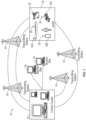
- the system includes a control center 12 that is in communication with a plurality of transmitting stations 14.
- the transmitting stations 14 transmit signals to the user devices 16.
- the control center 12 typically runs unattended with service personnel on call.
- Monitoring sites 18 act as receivers and provide real-time information to the control center 12 for detecting abnormalities. Feedback from the monitoring sites 18 may be used for providing differential corrections.
- a user device 16 may be disposed in various vehicles or may be hand held type devices. As illustrated, an airplane 16A, a ship 16B, an automotive vehicle 16C and a portal device 16D may incorporate a receiving system. In this example, the portal device 16D is a cellular phone. An antenna 20 is used for receiving signals at the various devices. The signals received may be time signals and location signal. As well, a data channel is also established within the eLoran system. The data channel conveys corrections, warnings and signal integrity information to the receivers associated with the user devices 16.
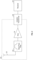
- the antenna 20 may be associated with a band pass filter 22 and an amplifier 24.
- the antenna 20, the band pass filter 22 and the amplifier 24 may be disposed on a substrate 26.
- the substrate 26 may be a dielectric substrate.
- the band pass filter 22 and the amplifier 24 may be disposed as separate components coupled between the antenna 20 and a receiver 30. Details of the antenna 20 are described in more detail below.
- the band pass filter 22 is used for filtering higher frequencies and lower frequencies than the band provided.
- a Chebyshev band pass filter is used. In an eLoran system, the center frequency is 100 kHz and the desirable frequencies are between 90 and 100 kHz to provide a total bandwidth of 20 kHz.
- the band pass filter 22 may be tuned differently.
- the amplifier 24 is used for amplifying the signal communicated from the band pass filter 22.
- a two stage amplifier using an LT6235 from Analog Devices Corp. was used.
- the LT6235 is a low noise, low power instrumentation amplifier.
- a second amplifier in series with the first amplifier was used.
- the LT1206 amplifier is a current feedback amplifier with high output current drive capability.
- various types of signal and multi-stage amplifiers may be used depending upon the signal received and the desired output characteristics.
- the receiver 30 receives the amplified signal from the amplifier 24.
- the receiver 30 processes the amplified signal to determine location, timing and other data therefrom.
- An isolation transformer 28 may be coupled to the substrate 26 or to the receiver 30 or both.
- the isolation transformer filters additional noise from the received signal. It was found that the isolation transformer 28 allows lower level signals to be discerned from the received signal.
- the antenna 20 is illustrated on a substrate 26.
- the substrate 26 contains only the antenna 20 and the circuitry such as the band pass filter 22, the amplifier 24 and the isolation transformer 28.
- the antenna 20 is formed from a planar outer conductive layer of a circuit board.
- a connector 40 is coupled to the circuit board.
- the connector 40 illustrated as a subminiature version A (SMA) connector.
- the SMA connector 40 is a semi-precision coaxial RF connector.
- the connector 40 has an outer portion 42 and an inner portion 44.
- the outer portion 42 is coupled to a ground plane 46 that has two ground plane portions 46A, 46B.
- the ground plane 46A, 46B are electrically in communication through the outer portions 42.
- the ground planes 46A, 46B are disposed laterally relative to an elongated feed 48.
- the feed 48 has two elongated sides 49 adjacent to and spaced apart from the first ground plane 46A and the second ground plane 46B by gaps 50A and 50B in the electrically conductive layer of the substrate 26. Gaps 50A, 50B are used to separate the ground plane 46A from the feed 48 while gap 50B is used to space the ground plane 46B from the feed 48.
- the feed 48 comprises a first feed portion 48A and a second feed portion 48B that are spaced apart by a gap 52 in the conductive layer of the substrate 26.
- Coupling components 54 may be disposed over the gaps 50A, 50B and 52. That is, the coupling components 54 may be a combination of one or more electrical components. For example, a capacitor, a very high resistance resistor, such as a one megohm and diodes may be used as the coupling components.
- the coupling components may be also be an inductor. The size of the components, for example, the capacitance, the resistance, the inductance or the type of diode varies depending upon the characteristics of the received signal.
- the antenna 20 has a longitudinal axis LA that extends through the connector and through the feed portions 48A, 48B.
- the longitudinal sides 49 of the feeds 48A, 48B including the gaps 50A, 50B are parallel to the longitudinal axis LA.
- the first end 56 of the feed 48 is triangular or angled and is coupled to the inner portion 44 of the connector 40.
- a second end 58 of the feed 48 is coupled to a meander 60.
- the meander 60 has a first end 62 coupled to the second end 58 of the feed 48.
- the meander 60 has a second end 64 that may be referred to as a common node as will be described in further detail below.
- the meander 60 has a longitudinal length between the first end 62 and the second end 64, which, in this example, is less than the longitudinal length of the feed.
- the meander 60 has a plurality of turns 70 that are formed from a plurality of lateral portions 66 and a plurality of longitudinal portions 68 that space out the lateral portions 66 in the longitudinal direction.
- the lateral portions 66 and the longitudinal portions 68 form right angles.
- the longitudinal portions 68 except the first and last longitudinal portions, extend symmetrically on each side of the longitudinal axis LA and have a length longer than the combination of the feed 48 and the gaps 50A, 50B.
- the number of turns 70 formed by the lateral portions 66 and the longitudinal portions 68 increase the efficiency. In this example, the number of turns 70 is twelve.
- the resonant frequency of the meander 60 decreases as the length of the longitudinal portions 68 increase.
- the size of the meander 60 varies depending upon the characteristics of the signal to be received.
- the meander 60 is elongated and the total length of the lateral portions 66 is longer than the longitudinal portions 68.
- the second end 64 is coupled to a first extension 80A and a second extension 80B.
- the first extension 80A comprises a first lateral portion 82A and the second extension 80B comprises a second lateral portion 82B.
- the lateral portions 82A, 82B extend laterally wider than the longitudinal portions of the turns 70 of the meander 60.
- the first extension 80A also has a longitudinal portion 84A extending longitudinally from the lateral portion 80A.
- the second extension 80B has a longitudinal portion 84B extending longitudinally from the lateral portion 82B.
- the longitudinal portion 84A, 84B are parallel to the longitudinal axis, in this example.
- the lateral portion 82A forms a right angle with the longitudinal portion 84A.
- the lateral portion 82B forms a right angle with the longitudinal portion 84B.
- Longitudinal portion 84A extends toward the ground plane 46A.
- the longitudinal portion 84B extends toward the ground plane 46B.
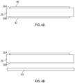
- the substrate 26 has a first side 26A and a second side 26B.
- the first side 26A has the components 88 illustrated in Fig. 3A , namely the ground plane 46A, 46B, the components of the meander 60 and the extensions 80A, 80B and its components making them coplanar.
- the ground plane 46 does not extend opposite the meander 60 of the substrate 26.
- the first side components 88 generally refer to the components described above on the first side 26A of the substrate 26.
- a second ground plane 90 may be disposed on the second side 26B of the substrate 26. The ground plane 90 may extend under the ground plane 46 and under the meander 60 and the first extension and the second extension 80A, 80B.
- the ground plane 90 is optional.
- the components 88 may be etched from the circuit board. That is, the substrate 26 may include a first metal side and a second metal side separate by a dielectric. The dielectric may be exposed in areas by cutting or chemically etching so that the components forming the meander are formed. The components forming the meander 60 may be referred to as a circuit trace. Likewise, the gaps 50A, 50B and 52 may be formed in a similar manner by etching or chemical removal. Another process for forming the antenna 20 is three dimensional printing.
- the ground plane 90' is separated from the second side of the substrate 26B. That is, the ground plane 90' may not be formed as part of the substrate 26 but rather a separate component or a component of the vehicle or device that is it mounted.
- the ground plane 90' may be the outer skin of a ship, airplane or car.
- a center frequency of 100 kHz is used with a 20 kHz bandwidth.
- the size of the various components used in one constructed embodiment are as follows: the length A of the lateral portions 66 was 23.93 mm. The length B of the lateral spacing between the longitudinal portions 84A, 84B was 37.96 mm. The length C corresponding to the lateral extent of the ground plane 46 was 6 in. The length D corresponding to the distance between the end of the longitudinal portions 84A, 84B of the first extension 80A and the second extension 80B was 10.725 mm. The length E corresponding to the distance between the ground plane and the lateral portions 82A, 82B was 43.73 mm.
- the length F between the furthest extent of the lateral portions 82A, 82B to the ground plane 46 is 1.75 in.
- the length G corresponds to the thickness of the meanders is 0.838 mm.
- the length H corresponding to the distance between two adjacent lateral portions of the meander is 2.46 mm.
- the length I corresponds to the longitudinal distance of the feed 48 and the length longitudinally of the ground plane 46.
- the length J corresponding to the distance from the angle to the connector 40 is 7.5 mm.
- the length K corresponding to the distance from the end of the terminals 42 to the connector 40 is 3.8 mm.
- the length L corresponding to the width of the feed 48 is 5 mm.
- the gap between the feed and each ground plane 46A, 46B is 0.676 in.
- the width end corresponding to the width of the end of the feed is 1.78 mm.
- the length O of the gap between the first end 56 of the feed 48 and the ground planes 46A and 46B is 1 mm.
- Example embodiments are provided so that this disclosure will be thorough and will fully convey the scope to those who are skilled in the art. Numerous specific details are set forth such as examples of specific components, devices, and methods, to provide a thorough understanding of embodiments of the present disclosure. It will be apparent to those skilled in the art that specific details need not be employed, that example embodiments may be embodied in many different forms and that neither should be construed to limit the scope of the disclosure. In some example embodiments, well-known processes, well-known device structures, and well-known technologies are not described in detail.
- first, second, third, etc. may be used herein to describe various elements, components, regions, layers and/or sections, these elements, components, regions, layers and/or sections should not be limited by these terms. These terms may be only used to distinguish one element, component, region, layer or section from another region, layer or section. Terms such as “first,” “second,” and other numerical terms when used herein do not imply a sequence or order unless clearly indicated by the context. Thus, a first element, component, region, layer or section discussed below could be termed a second element, component, region, layer or section without departing from the teachings of the example embodiments.
- spatially relative terms such as “inner,” “outer,” “beneath,” “below,” “lower,” “above,” “upper,” and the like, may be used herein for ease of description to describe one element or feature's relationship to another element(s) or feature(s) as illustrated in the figures.
- Spatially relative terms may be intended to encompass different orientations of the device in use or operation in addition to the orientation depicted in the figures. For example, if the device in the figures is turned over, elements described as “below” or “beneath” other elements or features would then be oriented “above” the other elements or features.
- the example term “below” can encompass both an orientation of above and below.
- the device may be otherwise oriented (rotated 90 degrees or at other orientations) and the spatially relative descriptors used herein interpreted accordingly.
Landscapes
- Engineering & Computer Science (AREA)
- Physics & Mathematics (AREA)
- General Physics & Mathematics (AREA)
- Radar, Positioning & Navigation (AREA)
- Remote Sensing (AREA)
- Computer Networks & Wireless Communication (AREA)
- Details Of Aerials (AREA)
Claims (14)
- Antenne (20), umfassend:ein dielektrisches Substrat (26), das eine ebene Form aufweist, das dielektrische Substrat umfassend eine erste Seite (26A) und eine zweite Seite (26B),eine längliche Zuleitung (48), die auf der ersten Seite des Substrats angeordnet ist, die längliche Zuleitung umfassend eine erste, sich in Längsrichtung erstreckende Seite (49) und eine zweite, sich in Längsrichtung erstreckende Seite (49), wobei die längliche Zuleitung einen ersten Abschnitt (48A) umfasst, der durch ein Kopplungselement (54) von einem zweiten Abschnitt (48B) beabstandet ist,eine Grundfläche (46), die neben der Zuleitung auf der ersten Seite des Substrats angeordnet und von dieser beabstandet ist, wobei die Grundfläche einen ersten Grundflächenabschnitt (46A) neben und beabstandet von der ersten, sich in Längsrichtung erstreckenden Seite und einen zweiten Grundflächenabschnitt (46B) neben und beabstandet von der zweiten, sich in Längsrichtung erstreckenden Seite umfasst,ein Mäander (60), das ein erstes Ende (62) aufweist, das mit der länglichen Zuleitung verbunden ist, der Mäander umfassend ein zweites Ende (64), das gegenüber dem ersten Ende angeordnet ist, wobei die längliche Zuleitung und der Mäander koaxial um eine Längsachse (LA) sind, wobei das zweite Ende sich in Längsrichtung erstreckt, koaxial zur Längsachse ist und einen gemeinsamen Knoten bildet,eine erste Erweiterung (80A), die sich vom zweiten Ende neben dem Mäander am gemeinsamen Knoten erstreckt, die erste Erweiterung umfassend einen ersten seitlichen Abschnitt (82A), der sich vom zweiten Ende erstreckt, und einen ersten Längsabschnitt (84A), der sich vom ersten seitlichen Abschnitt erstreckt und neben dem Mäander angeordnet ist, undeine zweite Erweiterung (80B), die sich vom zweiten Ende neben dem Mäander am gemeinsamen Knoten erstreckt, die zweite Erweiterung umfassend einen zweiten seitlichen Abschnitt (82B), der sich vom zweiten Ende erstreckt, und einen zweiten Längsabschnitt (84B), der sich vom zweiten seitlichen Abschnitt erstreckt und neben dem Mäander auf einer dem ersten Längsabschnitt gegenüberliegenden Seite des Mäanders angeordnet ist.
- Antenne (20) nach Anspruch 1, wobei der erste Längsabschnitt (84A) und der zweite Längsabschnitt (84B) parallel sind.
- Antenne (20) nach Anspruch 1, wobei der erste Längsabschnitt (84A) und der zweite Längsabschnitt (84B) sich in Längsrichtung zur Grundfläche (46) erstrecken.
- Antenne (20) nach Anspruch 1, wobei eine Länge des ersten Längsabschnitts (84A) kleiner als eine Längslänge des Mäanders (60) ist.
- Antenne (20) nach Anspruch 1, wobei eine Längslänge des Mäanders (60) kleiner ist als eine Längslänge (I) der länglichen Zuleitung (48).
- Antenne (20) nach Anspruch 1, wobei eine Breite (A) des Mäanders größer ist als die Breite (L) der länglichen Zuleitung (48).
- Antenne (20) nach Anspruch 1, wobei der Mäander (60) eine Vielzahl von Windungen (70) umfasst.
- Antenne (20) nach Anspruch 7, wobei die Anzahl der Windungen (70) größer als 10 ist.
- Antenne (20) nach Anspruch 1, ferner umfassend eine erste Lücke zwischen der Grundfläche (46) und der länglichen Zuleitung (48).
- Antenne (20) nach Anspruch 1, ferner umfassend ein Verbindungselement (40), das elektrisch mit der länglichen Zuleitung (48) und der Grundfläche (46) verbunden ist.
- Antenne (20) nach Anspruch 1, wobei die längliche Zuleitung (48) und die Grundfläche (46) koplanar sind.
- Antenne (20) nach Anspruch 1, wobei die längliche Zuleitung (48), die Grundfläche (46), der Mäander (60), die erste Erweiterung (80A) und die zweite Erweiterung (80B) koplanar sind.
- Antenne (20) nach Anspruch 1, ferner umfassend eine zweite Grundfläche (90), die auf der zweiten Seite (26B) des Substrats (26) angeordnet ist.
- System (10), umfassenddie in Anspruch 1 erwähnte Antenne (20),einen Bandpassfilter (22) undeinen Verstärker (24).
Applications Claiming Priority (3)
| Application Number | Priority Date | Filing Date | Title |
|---|---|---|---|
| US202063125739P | 2020-12-15 | 2020-12-15 | |
| US17/545,483 US11757196B2 (en) | 2020-12-15 | 2021-12-08 | Antenna ELORAN communication system |
| PCT/US2021/072894 WO2022133428A1 (en) | 2020-12-15 | 2021-12-14 | Antenna eloran communication system |
Publications (2)
| Publication Number | Publication Date |
|---|---|
| EP4264740A1 EP4264740A1 (de) | 2023-10-25 |
| EP4264740B1 true EP4264740B1 (de) | 2025-02-19 |
Family
ID=79425316
Family Applications (1)
| Application Number | Title | Priority Date | Filing Date |
|---|---|---|---|
| EP21841170.0A Active EP4264740B1 (de) | 2020-12-15 | 2021-12-14 | Antennen-eloran-kommunikationssystem |
Country Status (2)
| Country | Link |
|---|---|
| EP (1) | EP4264740B1 (de) |
| WO (1) | WO2022133428A1 (de) |
Family Cites Families (6)
| Publication number | Priority date | Publication date | Assignee | Title |
|---|---|---|---|---|
| JP4023500B2 (ja) * | 2004-08-03 | 2007-12-19 | ソニー株式会社 | イヤホンアンテナ |
| US7180465B2 (en) * | 2004-08-13 | 2007-02-20 | Interdigital Technology Corporation | Compact smart antenna for wireless applications and associated methods |
| US7450077B2 (en) * | 2006-06-13 | 2008-11-11 | Pharad, Llc | Antenna for efficient body wearable applications |
| TW200803038A (en) * | 2006-06-23 | 2008-01-01 | Wistron Neweb Corp | A flat mini type digital television antenna |
| CN101174730B (zh) * | 2006-11-03 | 2011-06-22 | 鸿富锦精密工业(深圳)有限公司 | 印刷式天线 |
| KR101718761B1 (ko) * | 2015-11-16 | 2017-03-23 | 한국과학기술원 | 대각 방향의 방사를 위한 밀리미터파 대역 안테나 |
-
2021
- 2021-12-14 WO PCT/US2021/072894 patent/WO2022133428A1/en not_active Ceased
- 2021-12-14 EP EP21841170.0A patent/EP4264740B1/de active Active
Also Published As
| Publication number | Publication date |
|---|---|
| EP4264740A1 (de) | 2023-10-25 |
| WO2022133428A1 (en) | 2022-06-23 |
Similar Documents
| Publication | Publication Date | Title |
|---|---|---|
| EP3671956B1 (de) | Doppelfrequenz-patchantennen | |
| US7132984B2 (en) | Antenna with built-in filter | |
| US7392029B2 (en) | Method and apparatus for true diversity reception with single antenna | |
| EP0993069A2 (de) | Oberflächenmontierte zirkularpolarisierte Antenne und Kommunikationsgerät mit einer derartigen Antenne | |
| US20170149137A1 (en) | Antenna device | |
| US11749895B2 (en) | Stacked patch antenna devices and methods | |
| US8552922B2 (en) | Helix-spiral combination antenna | |
| US11217891B2 (en) | Antenna device | |
| US10224610B2 (en) | Mobile computing device antenna | |
| CN114256605A (zh) | 一种组合天线 | |
| CN113782970A (zh) | 车载天线组件及车载天线装置 | |
| US11757476B2 (en) | Radio frequency module and communication device | |
| US11757196B2 (en) | Antenna ELORAN communication system | |
| JP2006311478A (ja) | 円偏波マイクロストリップアンテナ及び円偏波マイクロストリップアンテナ装置 | |
| WO2022133428A1 (en) | Antenna eloran communication system | |
| JP2008278059A (ja) | 多周波共用送受信装置 | |
| CN205016670U (zh) | 一种多频贴片天线装置 | |
| KR100969274B1 (ko) | 비정방형 패치 안테나 | |
| CN219350663U (zh) | 一种车联网天线 | |
| RU72580U1 (ru) | Комбинированная антенна | |
| JPH09139625A (ja) | 複合アンテナ | |
| US12019164B1 (en) | Unintentional RF radiators filter protection for a cospas sarsat emergency locator transmitter (ELT) GNSS receiver | |
| KR100406965B1 (ko) | 범지구측위시스템용 안테나 내장형 듀플렉서 | |
| US9985352B2 (en) | Dynamically allocated broadband multi-tap antenna | |
| JP2018182362A (ja) | アンテナ装置 |
Legal Events
| Date | Code | Title | Description |
|---|---|---|---|
| STAA | Information on the status of an ep patent application or granted ep patent |
Free format text: STATUS: UNKNOWN |
|
| STAA | Information on the status of an ep patent application or granted ep patent |
Free format text: STATUS: THE INTERNATIONAL PUBLICATION HAS BEEN MADE |
|
| PUAI | Public reference made under article 153(3) epc to a published international application that has entered the european phase |
Free format text: ORIGINAL CODE: 0009012 |
|
| STAA | Information on the status of an ep patent application or granted ep patent |
Free format text: STATUS: REQUEST FOR EXAMINATION WAS MADE |
|
| 17P | Request for examination filed |
Effective date: 20230627 |
|
| AK | Designated contracting states |
Kind code of ref document: A1 Designated state(s): AL AT BE BG CH CY CZ DE DK EE ES FI FR GB GR HR HU IE IS IT LI LT LU LV MC MK MT NL NO PL PT RO RS SE SI SK SM TR |
|
| DAV | Request for validation of the european patent (deleted) | ||
| DAX | Request for extension of the european patent (deleted) | ||
| GRAP | Despatch of communication of intention to grant a patent |
Free format text: ORIGINAL CODE: EPIDOSNIGR1 |
|
| STAA | Information on the status of an ep patent application or granted ep patent |
Free format text: STATUS: GRANT OF PATENT IS INTENDED |
|
| INTG | Intention to grant announced |
Effective date: 20241031 |
|
| GRAS | Grant fee paid |
Free format text: ORIGINAL CODE: EPIDOSNIGR3 |
|
| GRAA | (expected) grant |
Free format text: ORIGINAL CODE: 0009210 |
|
| STAA | Information on the status of an ep patent application or granted ep patent |
Free format text: STATUS: THE PATENT HAS BEEN GRANTED |
|
| AK | Designated contracting states |
Kind code of ref document: B1 Designated state(s): AL AT BE BG CH CY CZ DE DK EE ES FI FR GB GR HR HU IE IS IT LI LT LU LV MC MK MT NL NO PL PT RO RS SE SI SK SM TR |
|
| P01 | Opt-out of the competence of the unified patent court (upc) registered |
Free format text: CASE NUMBER: APP_1346/2025 Effective date: 20250109 |
|
| REG | Reference to a national code |
Ref country code: GB Ref legal event code: FG4D |
|
| REG | Reference to a national code |
Ref country code: CH Ref legal event code: EP |
|
| REG | Reference to a national code |
Ref country code: DE Ref legal event code: R096 Ref document number: 602021026517 Country of ref document: DE |
|
| REG | Reference to a national code |
Ref country code: IE Ref legal event code: FG4D |
|
| REG | Reference to a national code |
Ref country code: NL Ref legal event code: MP Effective date: 20250219 |
|
| PG25 | Lapsed in a contracting state [announced via postgrant information from national office to epo] |
Ref country code: RS Free format text: LAPSE BECAUSE OF FAILURE TO SUBMIT A TRANSLATION OF THE DESCRIPTION OR TO PAY THE FEE WITHIN THE PRESCRIBED TIME-LIMIT Effective date: 20250519 |
|
| PG25 | Lapsed in a contracting state [announced via postgrant information from national office to epo] |
Ref country code: FI Free format text: LAPSE BECAUSE OF FAILURE TO SUBMIT A TRANSLATION OF THE DESCRIPTION OR TO PAY THE FEE WITHIN THE PRESCRIBED TIME-LIMIT Effective date: 20250219 |
|
| PG25 | Lapsed in a contracting state [announced via postgrant information from national office to epo] |
Ref country code: PL Free format text: LAPSE BECAUSE OF FAILURE TO SUBMIT A TRANSLATION OF THE DESCRIPTION OR TO PAY THE FEE WITHIN THE PRESCRIBED TIME-LIMIT Effective date: 20250219 |
|
| PG25 | Lapsed in a contracting state [announced via postgrant information from national office to epo] |
Ref country code: ES Free format text: LAPSE BECAUSE OF FAILURE TO SUBMIT A TRANSLATION OF THE DESCRIPTION OR TO PAY THE FEE WITHIN THE PRESCRIBED TIME-LIMIT Effective date: 20250219 |
|
| REG | Reference to a national code |
Ref country code: LT Ref legal event code: MG9D |
|
| PG25 | Lapsed in a contracting state [announced via postgrant information from national office to epo] |
Ref country code: IS Free format text: LAPSE BECAUSE OF FAILURE TO SUBMIT A TRANSLATION OF THE DESCRIPTION OR TO PAY THE FEE WITHIN THE PRESCRIBED TIME-LIMIT Effective date: 20250619 Ref country code: NO Free format text: LAPSE BECAUSE OF FAILURE TO SUBMIT A TRANSLATION OF THE DESCRIPTION OR TO PAY THE FEE WITHIN THE PRESCRIBED TIME-LIMIT Effective date: 20250519 |
|
| PG25 | Lapsed in a contracting state [announced via postgrant information from national office to epo] |
Ref country code: NL Free format text: LAPSE BECAUSE OF FAILURE TO SUBMIT A TRANSLATION OF THE DESCRIPTION OR TO PAY THE FEE WITHIN THE PRESCRIBED TIME-LIMIT Effective date: 20250219 |
|
| PG25 | Lapsed in a contracting state [announced via postgrant information from national office to epo] |
Ref country code: HR Free format text: LAPSE BECAUSE OF FAILURE TO SUBMIT A TRANSLATION OF THE DESCRIPTION OR TO PAY THE FEE WITHIN THE PRESCRIBED TIME-LIMIT Effective date: 20250219 |
|
| PG25 | Lapsed in a contracting state [announced via postgrant information from national office to epo] |
Ref country code: PT Free format text: LAPSE BECAUSE OF FAILURE TO SUBMIT A TRANSLATION OF THE DESCRIPTION OR TO PAY THE FEE WITHIN THE PRESCRIBED TIME-LIMIT Effective date: 20250620 Ref country code: LV Free format text: LAPSE BECAUSE OF FAILURE TO SUBMIT A TRANSLATION OF THE DESCRIPTION OR TO PAY THE FEE WITHIN THE PRESCRIBED TIME-LIMIT Effective date: 20250219 |
|
| PG25 | Lapsed in a contracting state [announced via postgrant information from national office to epo] |
Ref country code: GR Free format text: LAPSE BECAUSE OF FAILURE TO SUBMIT A TRANSLATION OF THE DESCRIPTION OR TO PAY THE FEE WITHIN THE PRESCRIBED TIME-LIMIT Effective date: 20250520 Ref country code: BG Free format text: LAPSE BECAUSE OF FAILURE TO SUBMIT A TRANSLATION OF THE DESCRIPTION OR TO PAY THE FEE WITHIN THE PRESCRIBED TIME-LIMIT Effective date: 20250219 |
|
| REG | Reference to a national code |
Ref country code: AT Ref legal event code: MK05 Ref document number: 1769245 Country of ref document: AT Kind code of ref document: T Effective date: 20250219 |
|
| PG25 | Lapsed in a contracting state [announced via postgrant information from national office to epo] |
Ref country code: SE Free format text: LAPSE BECAUSE OF FAILURE TO SUBMIT A TRANSLATION OF THE DESCRIPTION OR TO PAY THE FEE WITHIN THE PRESCRIBED TIME-LIMIT Effective date: 20250219 |
|
| PG25 | Lapsed in a contracting state [announced via postgrant information from national office to epo] |
Ref country code: SM Free format text: LAPSE BECAUSE OF FAILURE TO SUBMIT A TRANSLATION OF THE DESCRIPTION OR TO PAY THE FEE WITHIN THE PRESCRIBED TIME-LIMIT Effective date: 20250219 |
|
| PG25 | Lapsed in a contracting state [announced via postgrant information from national office to epo] |
Ref country code: DK Free format text: LAPSE BECAUSE OF FAILURE TO SUBMIT A TRANSLATION OF THE DESCRIPTION OR TO PAY THE FEE WITHIN THE PRESCRIBED TIME-LIMIT Effective date: 20250219 |
|
| PG25 | Lapsed in a contracting state [announced via postgrant information from national office to epo] |
Ref country code: IT Free format text: LAPSE BECAUSE OF FAILURE TO SUBMIT A TRANSLATION OF THE DESCRIPTION OR TO PAY THE FEE WITHIN THE PRESCRIBED TIME-LIMIT Effective date: 20250219 |
|
| PG25 | Lapsed in a contracting state [announced via postgrant information from national office to epo] |
Ref country code: AT Free format text: LAPSE BECAUSE OF FAILURE TO SUBMIT A TRANSLATION OF THE DESCRIPTION OR TO PAY THE FEE WITHIN THE PRESCRIBED TIME-LIMIT Effective date: 20250219 |
|
| PG25 | Lapsed in a contracting state [announced via postgrant information from national office to epo] |
Ref country code: EE Free format text: LAPSE BECAUSE OF FAILURE TO SUBMIT A TRANSLATION OF THE DESCRIPTION OR TO PAY THE FEE WITHIN THE PRESCRIBED TIME-LIMIT Effective date: 20250219 Ref country code: CZ Free format text: LAPSE BECAUSE OF FAILURE TO SUBMIT A TRANSLATION OF THE DESCRIPTION OR TO PAY THE FEE WITHIN THE PRESCRIBED TIME-LIMIT Effective date: 20250219 |
|
| PG25 | Lapsed in a contracting state [announced via postgrant information from national office to epo] |
Ref country code: RO Free format text: LAPSE BECAUSE OF FAILURE TO SUBMIT A TRANSLATION OF THE DESCRIPTION OR TO PAY THE FEE WITHIN THE PRESCRIBED TIME-LIMIT Effective date: 20250219 |
|
| PG25 | Lapsed in a contracting state [announced via postgrant information from national office to epo] |
Ref country code: SK Free format text: LAPSE BECAUSE OF FAILURE TO SUBMIT A TRANSLATION OF THE DESCRIPTION OR TO PAY THE FEE WITHIN THE PRESCRIBED TIME-LIMIT Effective date: 20250219 |
|
| REG | Reference to a national code |
Ref country code: DE Ref legal event code: R097 Ref document number: 602021026517 Country of ref document: DE |
|
| PLBE | No opposition filed within time limit |
Free format text: ORIGINAL CODE: 0009261 |
|
| STAA | Information on the status of an ep patent application or granted ep patent |
Free format text: STATUS: NO OPPOSITION FILED WITHIN TIME LIMIT |
|
| PGFP | Annual fee paid to national office [announced via postgrant information from national office to epo] |
Ref country code: GB Payment date: 20251229 Year of fee payment: 5 |
|
| PGFP | Annual fee paid to national office [announced via postgrant information from national office to epo] |
Ref country code: FR Payment date: 20251226 Year of fee payment: 5 |
|
| 26N | No opposition filed |
Effective date: 20251120 |
|
| PGFP | Annual fee paid to national office [announced via postgrant information from national office to epo] |
Ref country code: DE Payment date: 20251229 Year of fee payment: 5 |