EP4263985B1 - Anordnung zur führung eines bewegbaren möbelteils - Google Patents
Anordnung zur führung eines bewegbaren möbelteils Download PDFInfo
- Publication number
- EP4263985B1 EP4263985B1 EP21830922.7A EP21830922A EP4263985B1 EP 4263985 B1 EP4263985 B1 EP 4263985B1 EP 21830922 A EP21830922 A EP 21830922A EP 4263985 B1 EP4263985 B1 EP 4263985B1
- Authority
- EP
- European Patent Office
- Prior art keywords
- cable
- furniture part
- display element
- tensioning device
- assembly
- Prior art date
- Legal status (The legal status is an assumption and is not a legal conclusion. Google has not performed a legal analysis and makes no representation as to the accuracy of the status listed.)
- Active
Links
Images



Classifications
-
- E—FIXED CONSTRUCTIONS
- E05—LOCKS; KEYS; WINDOW OR DOOR FITTINGS; SAFES
- E05F—DEVICES FOR MOVING WINGS INTO OPEN OR CLOSED POSITION; CHECKS FOR WINGS; WING FITTINGS NOT OTHERWISE PROVIDED FOR, CONCERNED WITH THE FUNCTIONING OF THE WING
- E05F1/00—Closers or openers for wings, not otherwise provided for in this subclass
- E05F1/08—Closers or openers for wings, not otherwise provided for in this subclass spring-actuated, e.g. for horizontally sliding wings
- E05F1/16—Closers or openers for wings, not otherwise provided for in this subclass spring-actuated, e.g. for horizontally sliding wings for sliding wings
-
- E—FIXED CONSTRUCTIONS
- E05—LOCKS; KEYS; WINDOW OR DOOR FITTINGS; SAFES
- E05D—HINGES OR SUSPENSION DEVICES FOR DOORS, WINDOWS OR WINGS
- E05D15/00—Suspension arrangements for wings
- E05D15/06—Suspension arrangements for wings for wings sliding horizontally more or less in their own plane
- E05D15/0621—Details, e.g. suspension or supporting guides
-
- E—FIXED CONSTRUCTIONS
- E05—LOCKS; KEYS; WINDOW OR DOOR FITTINGS; SAFES
- E05D—HINGES OR SUSPENSION DEVICES FOR DOORS, WINDOWS OR WINGS
- E05D15/00—Suspension arrangements for wings
- E05D15/56—Suspension arrangements for wings with successive different movements
- E05D15/58—Suspension arrangements for wings with successive different movements with both swinging and sliding movements
-
- E—FIXED CONSTRUCTIONS
- E06—DOORS, WINDOWS, SHUTTERS, OR ROLLER BLINDS IN GENERAL; LADDERS
- E06B—FIXED OR MOVABLE CLOSURES FOR OPENINGS IN BUILDINGS, VEHICLES, FENCES OR LIKE ENCLOSURES IN GENERAL, e.g. DOORS, WINDOWS, BLINDS, GATES
- E06B3/00—Window sashes, door leaves, or like elements for closing wall or like openings; Layout of fixed or moving closures, e.g. windows in wall or like openings; Features of rigidly-mounted outer frames relating to the mounting of wing frames
- E06B3/32—Arrangements of wings characterised by the manner of movement; Arrangements of movable wings in openings; Features of wings or frames relating solely to the manner of movement of the wing
- E06B3/50—Arrangements of wings characterised by the manner of movement; Arrangements of movable wings in openings; Features of wings or frames relating solely to the manner of movement of the wing with more than one kind of movement
- E06B3/5045—Arrangements of wings characterised by the manner of movement; Arrangements of movable wings in openings; Features of wings or frames relating solely to the manner of movement of the wing with more than one kind of movement specially adapted for furniture
-
- E—FIXED CONSTRUCTIONS
- E05—LOCKS; KEYS; WINDOW OR DOOR FITTINGS; SAFES
- E05D—HINGES OR SUSPENSION DEVICES FOR DOORS, WINDOWS OR WINGS
- E05D15/00—Suspension arrangements for wings
- E05D15/56—Suspension arrangements for wings with successive different movements
- E05D15/58—Suspension arrangements for wings with successive different movements with both swinging and sliding movements
- E05D15/581—Suspension arrangements for wings with successive different movements with both swinging and sliding movements the swinging axis laying in the sliding direction
-
- E—FIXED CONSTRUCTIONS
- E05—LOCKS; KEYS; WINDOW OR DOOR FITTINGS; SAFES
- E05Y—INDEXING SCHEME ASSOCIATED WITH SUBCLASSES E05D AND E05F, RELATING TO CONSTRUCTION ELEMENTS, ELECTRIC CONTROL, POWER SUPPLY, POWER SIGNAL OR TRANSMISSION, USER INTERFACES, MOUNTING OR COUPLING, DETAILS, ACCESSORIES, AUXILIARY OPERATIONS NOT OTHERWISE PROVIDED FOR, APPLICATION THEREOF
- E05Y2201/00—Constructional elements; Accessories therefor
- E05Y2201/40—Motors; Magnets; Springs; Weights; Accessories therefor
- E05Y2201/47—Springs
-
- E—FIXED CONSTRUCTIONS
- E05—LOCKS; KEYS; WINDOW OR DOOR FITTINGS; SAFES
- E05Y—INDEXING SCHEME ASSOCIATED WITH SUBCLASSES E05D AND E05F, RELATING TO CONSTRUCTION ELEMENTS, ELECTRIC CONTROL, POWER SUPPLY, POWER SIGNAL OR TRANSMISSION, USER INTERFACES, MOUNTING OR COUPLING, DETAILS, ACCESSORIES, AUXILIARY OPERATIONS NOT OTHERWISE PROVIDED FOR, APPLICATION THEREOF
- E05Y2201/00—Constructional elements; Accessories therefor
- E05Y2201/60—Suspension or transmission members; Accessories therefor
- E05Y2201/606—Accessories therefor
- E05Y2201/61—Cooperation between suspension or transmission members
- E05Y2201/612—Cooperation between suspension or transmission members between carriers and rails
- E05Y2201/614—Anti-derailing means
-
- E—FIXED CONSTRUCTIONS
- E05—LOCKS; KEYS; WINDOW OR DOOR FITTINGS; SAFES
- E05Y—INDEXING SCHEME ASSOCIATED WITH SUBCLASSES E05D AND E05F, RELATING TO CONSTRUCTION ELEMENTS, ELECTRIC CONTROL, POWER SUPPLY, POWER SIGNAL OR TRANSMISSION, USER INTERFACES, MOUNTING OR COUPLING, DETAILS, ACCESSORIES, AUXILIARY OPERATIONS NOT OTHERWISE PROVIDED FOR, APPLICATION THEREOF
- E05Y2201/00—Constructional elements; Accessories therefor
- E05Y2201/60—Suspension or transmission members; Accessories therefor
- E05Y2201/622—Suspension or transmission members elements
- E05Y2201/624—Arms
- E05Y2201/626—Levers
-
- E—FIXED CONSTRUCTIONS
- E05—LOCKS; KEYS; WINDOW OR DOOR FITTINGS; SAFES
- E05Y—INDEXING SCHEME ASSOCIATED WITH SUBCLASSES E05D AND E05F, RELATING TO CONSTRUCTION ELEMENTS, ELECTRIC CONTROL, POWER SUPPLY, POWER SIGNAL OR TRANSMISSION, USER INTERFACES, MOUNTING OR COUPLING, DETAILS, ACCESSORIES, AUXILIARY OPERATIONS NOT OTHERWISE PROVIDED FOR, APPLICATION THEREOF
- E05Y2201/00—Constructional elements; Accessories therefor
- E05Y2201/60—Suspension or transmission members; Accessories therefor
- E05Y2201/622—Suspension or transmission members elements
- E05Y2201/644—Flexible elongated pulling elements
- E05Y2201/654—Cables
-
- E—FIXED CONSTRUCTIONS
- E05—LOCKS; KEYS; WINDOW OR DOOR FITTINGS; SAFES
- E05Y—INDEXING SCHEME ASSOCIATED WITH SUBCLASSES E05D AND E05F, RELATING TO CONSTRUCTION ELEMENTS, ELECTRIC CONTROL, POWER SUPPLY, POWER SIGNAL OR TRANSMISSION, USER INTERFACES, MOUNTING OR COUPLING, DETAILS, ACCESSORIES, AUXILIARY OPERATIONS NOT OTHERWISE PROVIDED FOR, APPLICATION THEREOF
- E05Y2201/00—Constructional elements; Accessories therefor
- E05Y2201/60—Suspension or transmission members; Accessories therefor
- E05Y2201/622—Suspension or transmission members elements
- E05Y2201/658—Members cooperating with flexible elongated pulling elements
-
- E—FIXED CONSTRUCTIONS
- E05—LOCKS; KEYS; WINDOW OR DOOR FITTINGS; SAFES
- E05Y—INDEXING SCHEME ASSOCIATED WITH SUBCLASSES E05D AND E05F, RELATING TO CONSTRUCTION ELEMENTS, ELECTRIC CONTROL, POWER SUPPLY, POWER SIGNAL OR TRANSMISSION, USER INTERFACES, MOUNTING OR COUPLING, DETAILS, ACCESSORIES, AUXILIARY OPERATIONS NOT OTHERWISE PROVIDED FOR, APPLICATION THEREOF
- E05Y2201/00—Constructional elements; Accessories therefor
- E05Y2201/60—Suspension or transmission members; Accessories therefor
- E05Y2201/622—Suspension or transmission members elements
- E05Y2201/658—Members cooperating with flexible elongated pulling elements
- E05Y2201/672—Tensioners, tension sensors
-
- E—FIXED CONSTRUCTIONS
- E05—LOCKS; KEYS; WINDOW OR DOOR FITTINGS; SAFES
- E05Y—INDEXING SCHEME ASSOCIATED WITH SUBCLASSES E05D AND E05F, RELATING TO CONSTRUCTION ELEMENTS, ELECTRIC CONTROL, POWER SUPPLY, POWER SIGNAL OR TRANSMISSION, USER INTERFACES, MOUNTING OR COUPLING, DETAILS, ACCESSORIES, AUXILIARY OPERATIONS NOT OTHERWISE PROVIDED FOR, APPLICATION THEREOF
- E05Y2400/00—Electronic control; Electrical power; Power supply; Power or signal transmission; User interfaces
- E05Y2400/80—User interfaces
- E05Y2400/81—Feedback to user, e.g. tactile
- E05Y2400/818—Visual
-
- E—FIXED CONSTRUCTIONS
- E05—LOCKS; KEYS; WINDOW OR DOOR FITTINGS; SAFES
- E05Y—INDEXING SCHEME ASSOCIATED WITH SUBCLASSES E05D AND E05F, RELATING TO CONSTRUCTION ELEMENTS, ELECTRIC CONTROL, POWER SUPPLY, POWER SIGNAL OR TRANSMISSION, USER INTERFACES, MOUNTING OR COUPLING, DETAILS, ACCESSORIES, AUXILIARY OPERATIONS NOT OTHERWISE PROVIDED FOR, APPLICATION THEREOF
- E05Y2900/00—Application of doors, windows, wings or fittings thereof
- E05Y2900/20—Application of doors, windows, wings or fittings thereof for furniture, e.g. cabinets
- E05Y2900/212—Doors disappearing in pockets in the furniture body
Definitions
- the invention relates to an arrangement for guiding a movable furniture part, preferably a sliding door or folding sliding door, on a fixed furniture part, preferably a furniture body, with the features of the preamble of claim 1.
- the invention further relates to a piece of furniture with such an arrangement and a method for assembling such an arrangement.
- the EP 1 394 349 A1 an arrangement for guiding a movable furniture part, wherein a compensation device for compensating a tilting moment of a furniture door or a support on which a furniture door can be arranged.
- the compensation device is designed as a cable pull device.
- the EP 0 019 076 A1 reveals such an arrangement.
- the object of the present invention is to overcome the described disadvantages according to the prior art. and to provide an arrangement which is improved compared to the prior art for guiding a movable furniture part, preferably a sliding door or folding-sliding door, on a fixed furniture part, preferably a furniture body, a piece of furniture with at least one such arrangement and a method for assembling such an arrangement.
- a movable furniture part preferably a sliding door or folding-sliding door
- the cable tensioning device comprises a display device for displaying a cable tension.
- the display device can be used to read whether the cable tension of the cable is within a range suitable for the function of the cable pulling device. If this is the case, the cable can be secured and thus kept under tension.
- the display device thus enables the cable tension to be checked, which significantly facilitates the assembly and also the checking of an arrangement according to the invention.
- a piece of furniture according to the invention is provided with at least one fixed furniture part, at least one movable furniture part and at least one arrangement according to one of the preceding claims, preferably wherein the piece of furniture has at least one shaft-shaped cavity in which the at least one movable furniture part can be arranged.
- the display device can comprise a display element with an indicator. This makes it easy to implement a display device.
- the display device comprises a force accumulator, preferably a spring, particularly preferably a tension spring, wherein the force accumulator applies a force to the display element.
- the display element has a tensioning element, via which the display element is in, preferably direct, operative connection with the at least one cable.
- the display element is formed in one piece. This facilitates an uncomplicated construction and cost-effective production of an arrangement according to the invention.
- the cable tensioning device comprises at least two locking elements for locking the at least one cable.
- the cable tensioning device has at least one actuating element, preferably at least two actuating elements, for actuating the locking elements.
- the cable tensioning device has a housing, wherein it can be particularly preferably provided that parts of the cable tensioning device and/or the display device are/is arranged at least partially within the housing.
- the housing thus protects parts of the cable tensioning device and/or the display device from external influences, in particular from transport damage or the like. Furthermore, it can be provided that the housing has a cable guide for guiding the at least one cable. This allows the cable to be guided easily and inexpensively in the area of the cable tensioning device.
- the at least one pivoting lever mechanism comprises at least two pivoting levers which are connected to one another in an articulated manner and which can be pivoted relative to one another when the carrier moves on the fixed furniture part.
- Figure 1a schematically shows a furniture item 100 in a perspective view, which may comprise different components, for example several compartments inside the furniture item 100.
- the fixed furniture part 3 is formed by a furniture body.
- a cavity 101 is provided on the side of the furniture 100, which is formed by two furniture walls 101a spaced apart from one another.
- a movable furniture part 2 in the form of a folding sliding door can be lowered into the cavity 101 when folded. When the folding sliding door is spread open, it covers the interior of the furniture 100.
- the folding sliding door is composed of two partial flaps, which are in the position according to the Figure 1 are folded together. From this folded position, the folding sliding doors 2 can be transferred into a spread-out position in which the partial flaps enclose an angle which is greater than 0°.
- a further part of the furniture 100 for example a cupboard, is arranged adjacent to the hollow space 101. If the folding sliding door is in an open position and the other part of the furniture 100 is closed, the folding sliding door and the other part of the furniture 100 form a continuous furniture front.
- Figure 2 shows an exploded view of a piece of furniture 100 with an arrangement 1 according to the invention in a perspective view.
- the second furniture wall 101a of the cavity 101 is not shown. It is clear that the folding sliding door is in a fully spread position.
- Two guide systems 4, 5 and a furniture wall 3 can also be seen.
- a support 6 is also visible.
- FIG 3 shows a part of a piece of furniture 100 with an arrangement 1 according to the invention. Again, a carrier 6 can be seen which is displaceably mounted on the two guide systems 1, 5.
- a compensation device 7 consisting of a cable pulling device 8 and a pivoting lever mechanism 12 is also shown.
- the pivot lever mechanism consists of a first 12a and a second pivot lever 12b.
- the first pivot lever 12a is arranged on the guide system 4 and is displaceable on the support 6.
- the second pivot lever 12b is arranged on the support 6 and centrally on the first pivot lever 12a.
- the cable pulling device 8 comprises a cable 8a and deflection rollers 8b, which are arranged on the furniture wall 101a and/or on one of the two guide systems 1, 5.
- the cable tensioning device 9 is arranged on the back of the carrier 6 and is therefore not visible.
- the Figure 4 shows an exploded view of a cable tensioning device 9 according to the invention.
- a base body 9c can be seen on which a display element 11 is rotatably mounted.
- the display element 11 has an indicator 11a, a tensioning element 11b and an actuating lever 11c.
- the display element is formed in one piece.
- a multi-part display element can also be provided.
- the one-piece display element 11 is designed in the same color as the indicator 11a.
- the indicator 11a is specially colored or has stickers or the like.
- the display element 11 is subjected to a force via a tension spring 10a.
- the display element 11 can be rotated manually via the actuating lever 11c.
- a housing 9d can also be seen, which has a recess 10b.
- the indicator 11a becomes visible in the recess 10b when the cable is sufficiently tensioned.
- a locking element 9a is also formed on the base body 9a.
- the second locking element 9a is arranged on the first locking element 9a via actuating elements 9b in the form of screws.
- the cable can be clamped between the locking elements 9a and thus locked.
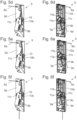
- FIGS. 5a to 5h show a cable tensioning device according to the invention in a perspective front view and the Figures 6a to 6h in a perspective rear view during a step of a method according to the invention.
- the Figures 5a to 5f and 6a to 6f show how a rope 8a is inserted into the rope tensioning device 9.
- the rope 8a is first passed through an opening in the housing 9d and then inserted into the housing 9d ( Fig. 5a to 5c or 6a to 6c).
- the housing 9d also serves as a rope guide for the rope 8a.
- the indicator element 11 is rotated via the actuating lever 11c against the force applied by the energy storage device 10.
- the cable 8a can then be passed between the indicator 11a and the tensioning element 11b ( Fig. 5d and 6d ).
- the cable 8a is then guided between the clamping elements 9a and out of the housing 9d ( Fig. 5e /f and 6e/f). Meanwhile, the display element 11 is held in the rotated position via the operating lever 11c.
- the actuating lever 11c can be released.
- the display element 11 is rotated in the direction of the original position due to the energy storage device 10a.
- the tensioning element 11b presses against the cable 8a and thus represents an effective connection between the display element 11 and the cable 8a.
- the cable 8a is slightly clamped, which prevents the cable 8a from slipping out of the cable tensioning device 9, for example during a transport process.
- the cable 8a presses against the tensioning element 11b due to the tension and in doing so twists the indicator element 11 against the force applied by the energy storage device 10a. If the cable tension is sufficiently high, the indicator element 11 is twisted so far that the indicator 11a can be seen through the recess 10b. The indicator device 10 shows that the cable tension is sufficient.
- the rope can be secured via the clamping elements 9a by operating the actuating elements 9b while maintaining the rope tension ( Fig.5g/6g ).
- One end of the rope 8a can be stowed in an opening of the carrier 6 in the last step ( Fig. 5h/6h ).
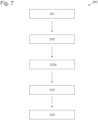
- the Figure 7 shows a flow chart of a preferred method 200 for mounting an arrangement 1 according to the invention on a furniture wall 3.
- the order of the method steps 201 to 204 of the method 200 can be seen.
Landscapes
- Engineering & Computer Science (AREA)
- Mechanical Engineering (AREA)
- Civil Engineering (AREA)
- Structural Engineering (AREA)
- Installation Of Indoor Wiring (AREA)
- Closing And Opening Devices For Wings, And Checks For Wings (AREA)
- Freezers Or Refrigerated Showcases (AREA)
- Devices For Conveying Motion By Means Of Endless Flexible Members (AREA)
- Support Devices For Sliding Doors (AREA)
- Display Racks (AREA)
- Drawers Of Furniture (AREA)
- Devices For Indicating Variable Information By Combining Individual Elements (AREA)
- Transmission Devices (AREA)
- Cabinets, Racks, Or The Like Of Rigid Construction (AREA)
- Instructional Devices (AREA)
Description
- Die Erfindung betrifft eine Anordnung zur Führung eines bewegbaren Möbelteils, vorzugsweise einer Schiebetür oder Falt-Schiebetür, an einem feststehenden Möbelteil, vorzugsweise einem Möbelkorpus, mit den Merkmalen des Oberbegriffs des Anspruchs 1. Die Erfindung betrifft weiterhin ein Möbel mit einer solchen Anordnung sowie ein Verfahren zur Montage einer solchen Anordnung.
- Anordnungen gemäß dem Oberbegriff des Anspruchs 1 sind bereits bekannt. Beispielsweise zeigt die
EP 1 394 349 A1 eine Anordnung zur Führung eines bewegbaren Möbelteils, wobei eine Kompensationsvorrichtung zur Kompensation eines Kippmoments einer Möbeltüre oder eines Trägers, an welchem eine Möbeltüre angeordnet sein kann, aufweist. Die Kompensationsvorrichtung ist dabei als Seilzugvorrichtung ausgeführt. Auch dieEP 0 019 076 A1 offenbart eine solche Anordnung. - Nachteilig bei solchen Lösungen gemäß dem Stand der Technik ist, dass die richtige Spannung des Seils nur sehr schwer oder gar nicht überprüft werden kann. Wenn das Seil nicht ausreichend oder aber zu fest gespannt ist, so hat dies negative Auswirkungen auf die Funktion einer Seilzugvorrichtung. Im schlechtesten Fall funktioniert die Seilzugvorrichtung nicht ordnungsgemäß, was zu einer Beschädigung eines bewegbaren und/oder feststehenden Möbelteils bzw. eines Möbels führen kann.
- Die Aufgabe der vorliegenden Erfindung besteht darin, die beschriebenen Nachteile gemäß dem Stand der Technik zu vermeiden und eine gegenüber dem Stand der Technik verbesserte Anordnung zur Führung eines bewegbaren Möbelteils, vorzugsweise einer Schiebetür oder Falt-Schiebetür, an einem feststehenden Möbelteil, vorzugsweise einem Möbelkorpus, ein Möbel mit zumindest einer solchen Anordnung und ein Verfahren zur Montage einer solchen Anordnung anzugeben.
- Diese Aufgaben werden gelöst durch die Merkmale der unabhängigen Ansprüche 1, 12 und 13.
- Erfindungsgemäß ist es demnach vorgesehen, dass die Seilspannvorrichtung eine Anzeigevorrichtung zum Anzeigen einer Seilspannung umfasst. Über die Anzeigevorrichtung kann abgelesen werden, ob sich die Seilspannung des Seils in einem für die Funktion der Seilzugvorrichtung geeigneten Rahmen befindet. Ist dies der Fall, so kann das Seil festgestellt und somit unter Spannung gehalten werden. Über die Anzeigevorrichtung wird somit eine Kontrolle der Seilspannung ermöglicht, was die Montage und auch Überprüfung einer erfindungsgemäßen Anordnung signifikant erleichtert.
- Es ist weiters ein erfindungsgemäßes Möbel mit zumindest einem feststehenden Möbelteil, zumindest einem bewegbaren Möbelteil und wenigstens einer Anordnung nach einem der vorangehenden Ansprüche, vorzugsweise wobei das Möbel zumindest einen schachtförmiger Hohlraum aufweist, in welchem das zumindest eine bewegbare Möbelteil anordenbar ist, vorgesehen.
- Außerdem ist ein erfindungsgemäßes Verfahren zur Montage einer Anordnung nach einem der vorangehenden Ansprüche vorgesehen, wobei
- in einem ersten Verfahrensschritt das zumindest eine Führungssystem an dem feststehenden Möbelteil befestigt wird,
- in einem zweiten Verfahrensschritt der Träger mit dem zumindest einen Führungssysteme bewegungsgekoppelt verbunden wird, und
- in einem dritten Verfahrensschritt das Seil der Seilzugvorrichtung mittels des Seilspannvorrichtung gespannt wird.
- Weitere vorteilhafte Ausführungsformen der Erfindung werden in den abhängigen Ansprüchen definiert.
- Besonders bevorzugt kann vorgesehen sein, dass die Anzeigevorrichtung ein Anzeigeelement mit einem Indikator umfasst. Dadurch lässt sich eine Anzeigevorrichtung einfach realisieren.
- Es kann vorgesehen sein, dass die Anzeigevorrichtung einen Kraftspeicher, bevorzugt eine Feder, besonders bevorzugt eine Zugfeder, umfasst, wobei der Kraftspeicher das Anzeigeelement mit einer Kraft beaufschlagt.
- Weiters kann vorgesehen sein, dass das Anzeigeelement ein Spannelement aufweist, über welches das Anzeigeelement in, vorzugsweise unmittelbarer, Wirkverbindung mit dem zumindest einen Seil steht.
- Dadurch kann eine einfache Koppelung des Anzeigeelements mit dem Seil erreicht werden.
- In einem Ausführungsbeispiel der Erfindung kann vorgesehen sein, dass das Anzeigeelement einstückig ausgebildet ist. Dies begünstigt einen unkomplizierten Aufbau und eine kostengünstige Fertigung einer erfindungsgemäßen Anordnung.
- Gemäß einem weiteren Ausführungsbeispiel der Erfindung kann es vorgesehen sein, dass die Seilspannvorrichtung zumindest zwei Feststellelemente zum Feststellen des zumindest einen Seils umfasst.
- Zusätzlich dazu kann vorgesehen sein, dass die Seilspannvorrichtung zumindest ein Betätigungselement, vorzugsweise zumindest zwei Betätigungselemente, zum Betätigen der Feststellelemente aufweist.
- Dadurch wird ein unkompliziertes Feststellen des Seils ermöglicht.
- Bevorzugt kann vorgesehen sein, dass die Seilspannvorrichtung ein Gehäuse aufweist, wobei besonders bevorzugt vorgesehen sein kann, dass Teile der Seilspannvorrichtung und/oder die Anzeigevorrichtung zumindest teilweise innerhalb des Gehäuses angeordnet sind/ist.
- Das Gehäuse schützt somit Teile der Seilspannvorrichtung und/oder die Anzeigevorrichtung vor äußeren Einflüssen, insbesondere vor Transportschäden oder dergleichen. Weiters kann vorgesehen sein, dass das Gehäuse eine Seilführung zur Führung des zumindest einen Seils aufweist. Dadurch kann das Seil einfach und kostengünstig im Bereich der Seilspannvorrichtung geführt werden.
- Besonders bevorzugt kann vorgesehen sein, dass zusätzlich zur wenigstens einen Seilzugvorrichtung wenigstens einen Schwenkhebelmechanismus aufweist, wobei der wenigstens eine Schwenkhebelmechanismus wenigstens zwei gelenkig miteinander verbundene Schwenkhebel umfasst, welche bei einer Bewegung des Trägers am feststehenden Möbelteil relativ zueinander verschwenkbar sind.
- Hinsichtlich eines erfindungsgemäßen Verfahrens kann vorgesehen sein, dass der dritte Verfahrensschritt folgende Schritte umfasst:
- Einbringen des Seils in die Seilspannvorrichtung,
- Spannen des Seils, bis die Anzeigevorrichtung eine ausreichende Seilspannung attestiert,
- Feststellen des gespannten Seils mittels der zumindest zwei Feststellelemente der Seilspannvorrichtung, und
- Verstauen eines Seilendes des Seils im oder am Träger.
- Weitere Einzelheiten und Vorteile der Erfindung werden anhand der Figurenbeschreibung unter Bezugnahme auf die Zeichnungen im Folgenden näher erläutert. Darin zeigen:
- Fig. 1
- ein Möbel mit einer erfindungsgemäßen Anordnung in einer perspektivischen Ansicht,
- Fig. 2
- eine Explosionsdarstellung eines Möbels mit einer erfindungsgemäßen Anordnung in einer perspektivischen Ansicht,
- Fig. 3
- einen Teil eines Möbels mit einer erfindungsgemäßen Anordnung,
- Fig. 4
- eine Explosionsdarstellung einer erfindungsgemäßen Seilspannvorrichtung,
- Fig. 5a-h
- eine erfindungsgemäße Seilspannvorrichtung in einer perspektivischen Frontansicht während eines Schritts eines erfindungsgemäßen Verfahrens,
- Fig. 6a-h
- eine erfindungsgemäße Seilspannvorrichtung perspektivischen Hinteransicht während eines Schritts eines erfindungsgemäßen Verfahrens, und
- Fig. 7
- ein Ablaufdiagramm eines erfindungsgemäßen Verfahrens.
- In der Figur 1a ist schematisch in einer perspektivischen Ansicht ein Möbel 100 dargestellt, welches unterschiedliche Bestandteile umfassen kann, beispielsweise mehrere Fächer im Inneren des Möbels 100. Das feststehende Möbelteil 3 wird durch einen Möbelkorpus gebildet.
- Seitlich vom Möbel 100 ist ein Hohlraum 101 vorgesehen, welcher aus zwei voneinander beabstandeten Möbelwänden 101a gebildet wird. In den Hohlraum 101 ist ein bewegbares Möbelteil 2 in Form einer Falt-Schiebetür im zusammengefalteten Zustand versenkbar. Ist die Falt-Schiebetür aufgespreizt, so verdeckt sie das Innere des Möbels 100.
- Die Falt-Schiebetür ist aus zwei Teilklappen zusammengesetzt, die in der Stellung gemäß der
Figur 1 zusammengefaltet sind. Aus dieser zusammengefalteten Stellung können die Falt-Schiebetüren 2 in eine aufgespreizte Stellung überführt werden, in welche die Teilklappen einen Winkel einschließen, welche größer als 0° ist. - An den Hohlraum 101 anschließend ist ein weiterer Teil des Möbels 100 angeordnet, beispielsweise ein Schrank. Befindet sich die Falt-Schiebetür in einer aufgespreizten Stellung und ist der weitere Teil des Möbels 100 geschlossen, so bilden die Falt-Schiebetür und der weitere Teil des Möbels 100 eine durchgängige Möbelfront.
-
Figur 2 zeigt eine Explosionsdarstellung eines Möbels 100 mit einer erfindungsgemäßen Anordnung 1 in einer perspektivischen Ansicht. Zum besseren Verständnis ist die zweite Möbelwand 101a des Hohlraums 101 nicht dargestellt. Es ist ersichtlich, dass sich die Falt-Schiebetüre in einer vollständig aufgespreizten Stellung befindet. Es sind weiters ein zwei Führungssysteme 4, 5 und eine Möbelwand 3 erkennbar. Auch ein Träger 6 ist ersichtlich. - Die
Figur 3 zeigt einen Teil eines Möbels 100 mit einer erfindungsgemäßen Anordnung 1. Es ist wiederum ein Träger 6 erkennbar, welcher an den zwei Führungssystemen 1, 5 verschiebbar gelagert ist. - Eine Kompensationsvorrichtung 7 bestehend aus einer Seilzugvorrichtung 8 und einem Schwenkhebelmechanismus 12 ist ebenfalls dargestellt. Der Schwenkhebelmechanismus besteht aus eine ersten 12a und einem zweiten Schwenkhebel 12b. Der erste Schwenkhebel 12a ist am Führungssystem 4 und verschiebbar am Träger 6 angeordnet. Der zweite Schwenkhebel 12b ist am Träger 6 und mittig am ersten Schwenkhebel 12a angeordnet. Die Seilzugvorrichtung 8 umfasst ein Seil 8a und Umlenkrollen 8b, welche an der Möbelwand 101a und/oder an einem der beiden Führungssysteme 1, 5 angeordnet sind.
- Die Seilspannvorrichtung 9 ist an der Rückseite des Trägers 6 angeordnet und daher nicht ersichtlich.
- Die
Figur 4 zeigt eine Explosionsdarstellung einer erfindungsgemäßen Seilspannvorrichtung 9. Es ist ein Grundkörper 9c erkennbar, an welchem ein Anzeigeelement 11 drehbar gelagert ist. - Das Anzeigeelement 11 weist einen Indikator 11a, ein Spannelement 11b sowie einen Betätigungshebel 11c auf. Im vorliegenden Ausführungsbeispiel ist das Anzeigeelement einstückig ausgebildet. Es kann aber auch ein mehrteiliges Anzeigeelement vorgesehen sein.
- Im vorliegenden Ausführungsbeispiel ist das einstückige Anzeigeelement 11 in jener Farbe ausgeführt, welche auch der Indikator 11a aufweisen soll. Es kann aber auch vorgesehen sein, dass der Indikator 11a extra eingefärbt ist oder aber Aufkleber o.a. aufweist.
- Das Anzeigeelement 11 ist über eine Zugfeder 10a mit einer Kraft beaufschlagt. Über den Betätigungshebel 11c kann das Anzeigeelement 11 händisch verdreht werden.
- Es ist weiters ein Gehäuse 9d erkennbar, welches eine Ausnehmung 10b aufweist. In der Ausnehmung 10b wird im zusammengebauten Zustand bei ausreichender Seilspannung der Indikator 11a sichtbar.
- Am Grundkörper 9a ist weiters ein Feststellelement 9a ausgebildet ist. Das zweite Feststellelement 9a wird über Betätigungselemente 9b in Form von Schrauben am ersten Feststellelement 9a angeordnet. Das Seil kann zwischen den Feststellelementen 9a geklemmt und somit festgestellt werden.
- Die
Figuren 5a bis 5h zeigen eine erfindungsgemäße Seilspannvorrichtung in einer perspektivischen Front- und dieFiguren 6a bis 6h in einer perspektivischen Hinteransicht während eines Schritts eines erfindungsgemäßen Verfahrens. - Die
Figuren 5a bis 5f und 6a bis 6f zeigen, wie ein Seil 8a in die Seilspannvorrichtung 9 eingeführt wird. Das Seil 8a wird zuerst durch eine Öffnung im Gehäuse 9d durchgeführt und anschließend in das Gehäuse 9d eingeführt (Fig. 5a bis 5c bzw. 6a bis 6c). Das Gehäuse 9d dient dabei auch als Seilführung für das Seil 8a. - In den
Figuren 6a bis 6c ist jeweils der Grundkörper 9c nicht dargestellt Es ist erkennbar, dass das Anzeigeelement 11 nicht bewegt wird. - In einem nächsten Schritt wird das Anzeigeelement 11 über den Betätigungshebel 11c entgegen der durch den Kraftspeicher 10 aufgebrachten Kraft verdreht. Danach kann das Seil 8a zwischen dem Indikator 11a und dem Spannelement 11b durchgeführt werden (
Fig. 5d und 6d ). - Anschließend wird das Seil 8a zwischen den Klemmelementen 9a hindurch und aus dem Gehäuse 9d herausgeführt (
Fig. 5e /f und 6e/f). Währenddessen wird das Anzeigeelement 11 über den Betätigungshebel 11c in der verdrehten Position gehalten. - Ist das Seil 8a derart in der Seilspannvorrichtung 9 angeordnet, so kann der Betätigungshebel 11c losgelassen werden. Das Anzeigeelement 11 wird aufgrund des Kraftspeichers 10a in Richtung der ursprünglichen Position verdreht. Dabei drückt das Spannelement 11b gegen das Seil 8a und stellt somit eine Wirkverbindung zwischen dem Anzeigeelement 11 und dem Seil 8a dar. Gleichzeitig wird das Seil 8a dadurch leicht geklemmt, was ein herausrutschen des Seils 8a aus der Seilspannvorrichtung 9, beispielsweise bei einem Transportvorgang, verhindert.
- Wird das Seil 8a nun gespannt, so drückt das Seil aufgrund der Spannung gegen das Spannelement 11b und verdreht dabei das Anzeigeelement 11 gegen die durch den Kraftspeicher 10a aufgebrachte Kraft. Ist die Seilspannung ausreichend groß, so ist das Anzeigeelement 11 soweit verdreht, dass der Indikator 11a durch die Ausnehmung 10b erkennbar ist. Die Anzeigevorrichtung 10 zeigt eine ausreichende Seilspannung an.
- Nun kann das Seil unter Aufrechterhaltung der Seilspannung, durch Betätigung der Betätigungselemente 9b, über die Klemmelemente 9a festgestellt werden (
Fig. 5g/6g ). Ein Seilende des Seils 8a kann im letzten Schritt in einer Öffnung des Trägers 6 verstaut werden (Fig. 5h/6h ). - Die
Figur 7 zeigt ein Flussdiagramm eines bevorzugten Verfahrens 200 zur Montage einer erfindungsgemäßen Anordnung 1 an einer Möbelwand 3. Es ist die Reihenfolge der Verfahrensschritte 201 bis 204 des Verfahrens 200 zu erkennen. -
- 1
- Anordnung
- 2
- Bewegbares Möbelteil
- 3
- Feststehendes Möbelteil
- 4
- Führungssystem
- 5
- Führungssystem
- 6
- Träger
- 7
- Kompensationsvorrichtung
- 8
- Seilzugvorrichtung
8a Seil
8b Umlenkrolle - 9
- Seilspannvorrichtung
9a Feststellelemente
9b Betätigungselement
9c Grundkörper
9d Gehäuse - 10
- Anzeigevorrichtung
10a Kraftspeicher
10b Ausnehmung - 11
- Anzeigeelement
11a Indikator
11b Spannelement
11c Betätigungshebel - 12
- Schwenkhebelmechanismus
12a erster Schwenkhebel
12b zweiter Schwenkhebel - 100
- Möbel
- 101
- Hohlraum
101a Möbelwand
Claims (15)
- Anordnung (1) zur Führung eines bewegbaren Möbelteils (2), vorzugsweise einer Schiebetür oder Falt-Schiebetür, an einem feststehenden Möbelteil (3), vorzugsweise einem Möbelkorpus, mit- zumindest einem an dem feststehenden Möbelteil (3) zu befestigenden Führungssystem (4, 5)- einem Träger (6), an welchem das bewegbare Möbelteil (2) schwenkbar gelagert oder lagerbar ist,- einer Kompensationsvorrichtung (7) zur Kompensation eines Kippmoments des Trägers (6) oder des daran angeordneten bewegbaren Möbelteils (2) um eine Kippachse durch ein Rückstellmoment, wobei die Kompensationsvorrichtung (7) wenigstens eine Seilzugvorrichtung (8) mit zumindest einem Seil (8a) umfasst, und- einer Seilspannvorrichtung (9) zum Spannen des zumindest einen Seils (8a),dadurch gekennzeichnet, dass die Seilspannvorrichtung (9) eine Anzeigevorrichtung (10) zum Anzeigen einer Seilspannung umfasst.
- Anordnung nach Anspruch 1, dadurch gekennzeichnet, dass die Anzeigevorrichtung (10) ein Anzeigeelement (11) mit einem Indikator (11a) umfasst, vorzugsweise wobei die Anzeigevorrichtung (10) einen Kraftspeicher (10a), bevorzugt eine Feder, besonders bevorzugt eine Zugfeder, umfasst, wobei der Kraftspeicher (10a) das Anzeigeelement (11) mit einer Kraft beaufschlagt.
- Anordnung nach einem der Ansprüche 1 oder 2, dadurch gekennzeichnet, dass das Anzeigeelement (11) ein Spannelement (11b) aufweist, über welches das Anzeigeelement (11) in, vorzugsweise unmittelbarer, Wirkverbindung mit dem zumindest einen Seil (8a) steht, und/oder, dass das Anzeigeelement (11) einen Betätigungshebel (11c) zum manuellen Betätigen des Anzeigeelements (11) umfasst, und/oder, dass das Anzeigeelement (11) einstückig ausgebildet ist.
- Anordnung nach einem der Ansprüche 1 bis 3, dadurch gekennzeichnet, dass die Seilspannvorrichtung (9) zumindest zwei Feststellelemente (9a) zum Feststellen des zumindest einen Seils (8a) umfasst, vorzugsweise wobei die Seilspannvorrichtung (4) zumindest ein Betätigungselement (9b), vorzugsweise zumindest zwei Betätigungselemente (9b), zum Betätigen der Feststellelemente (9a) aufweist.
- Anordnung nach einem der Ansprüche 1 bis 4, dadurch gekennzeichnet, dass die Seilspannvorrichtung (9) einen Grundkörper (9c) umfasst, vorzugsweise wobei das Anzeigeelement (11) bewegbar, vorzugsweise drehbar, am Grundkörper (9c) gelagert ist.
- Anordnung nach einem der Ansprüche 4 oder 5, dadurch gekennzeichnet, dass zumindest eines der zumindest zwei Feststellelemente (9a) am Grundkörper (9c) ausgebildet ist.
- Anordnung nach einem der Ansprüche 1 bis 5, dadurch gekennzeichnet, dass die Seilspannvorrichtung (9) ein Gehäuse (9d) aufweist, vorzugsweise wobei die Anzeigevorrichtung (1) eine Ausnehmung (10d) in dem Gehäuse (9c) umfasst.
- Anordnung nach Anspruch 7, dadurch gekennzeichnet, dass das Gehäuse (9c) eine Seilführung zur Führung des zumindest einen Seils (13a) aufweist.
- Anordnung nach einem der Ansprüche 7 oder 8, dadurch gekennzeichnet, dass Teile der Seilspannvorrichtung (9) und/oder die Anzeigevorrichtung (10) zumindest teilweise innerhalb des Gehäuses (9c) angeordnet sind/ist.
- Anordnung nach einem der Ansprüche 1 bis 9, dadurch gekennzeichnet, dass zusätzlich zur wenigstens einen Seilzugvorrichtung (8) wenigstens ein Schwenkhebelmechanismus (12) vorgesehen ist, wobei der wenigstens eine Schwenkhebelmechanismus (12) wenigstens zwei gelenkig miteinander verbundene Schwenkhebel (12a, 12b) umfasst, welche bei einer Bewegung des Trägers (6) am feststehenden Möbelteil (3) relativ zueinander verschwenkbar sind.
- Anordnung (1) nach einem der Ansprüche 1 bis 10, wobei die Kompensationsvorrichtung (7) in einem Auslieferungszustand der Anordnung (1) zumindest teilweise, vorzugsweise vollständig, am Träger (6) vormontiert ist.
- Möbel (100) mit zumindest einem feststehenden Möbelteil (3), zumindest einem bewegbaren Möbelteil (2) und wenigstens einer Anordnung (1) nach einem der vorangehenden Ansprüche, vorzugsweise wobei das Möbel (100) zumindest einen schachtförmiger Hohlraum (101) aufweist, in welchem das zumindest eine bewegbare Möbelteil (2) anordenbar ist.
- Verfahren (200) zur Montage einer Anordnung (1) nach einem der vorangehenden Ansprüche, wobei- in einem ersten Verfahrensschritt (201) das zumindest eine Führungssystem (4, 5) an dem feststehenden Möbelteil (3) befestigt wird,- in einem zweiten Verfahrensschritt (202) der Träger (6) mit dem zumindest einen Führungssysteme (4, 5) bewegungsgekoppelt verbunden wird, und- in einem dritten Verfahrensschritt (203) das Seil (8a) der Seilzugvorrichtung (8) mittels des Seilspannvorrichtung (9) gespannt wird.
- Verfahren nach Anspruch 13, dadurch gekennzeichnet, dass der dritte Verfahrensschritt (203) folgende Schritte umfasst:- Einbringen des Seils (13a) in die Seilspannvorrichtung (9),- Spannen des Seils (13a), bis die Anzeigevorrichtung (10) eine ausreichende Seilspannung attestiert,- Feststellen des gespannten Seils (13a) mittels der zumindest zwei Feststellelemente (9a) der Seilspannvorrichtung (9), und- Verstauen eines Seilendes des Seils (13a) im oder am Träger (6).
- Verfahren nach einem der Ansprüche 13 oder 14, dadurch gekennzeichnet, dass in einem Zwischenschritt (202a) zumindest einer der wenigstens zwei Schwenkhebel (12a, 12b) mit dem zumindest einen Führungssystem (4, 5) und/oder mit dem feststehenden Möbelteil (3) verbunden wird und/oder wobei in einem weiteren Verfahrensschritt (204) ein bewegbares Möbelteil (2), vorzugsweise eine Schiebetür oder Falt-Schiebetür, am Träger (6) montiert wird.
Priority Applications (1)
| Application Number | Priority Date | Filing Date | Title |
|---|---|---|---|
| EP24170262.0A EP4375465A3 (de) | 2020-12-17 | 2021-12-14 | Anordnung zur führung eines bewegbaren möbelteils |
Applications Claiming Priority (2)
| Application Number | Priority Date | Filing Date | Title |
|---|---|---|---|
| ATA51103/2020A AT524332B1 (de) | 2020-12-17 | 2020-12-17 | Anordnung zur Führung eines bewegbaren Möbelteils |
| PCT/AT2021/060474 WO2022126165A1 (de) | 2020-12-17 | 2021-12-14 | Anordnung zur führung eines bewegbaren möbelteils |
Related Child Applications (1)
| Application Number | Title | Priority Date | Filing Date |
|---|---|---|---|
| EP24170262.0A Division EP4375465A3 (de) | 2020-12-17 | 2021-12-14 | Anordnung zur führung eines bewegbaren möbelteils |
Publications (2)
| Publication Number | Publication Date |
|---|---|
| EP4263985A1 EP4263985A1 (de) | 2023-10-25 |
| EP4263985B1 true EP4263985B1 (de) | 2024-04-24 |
Family
ID=79024856
Family Applications (2)
| Application Number | Title | Priority Date | Filing Date |
|---|---|---|---|
| EP21830922.7A Active EP4263985B1 (de) | 2020-12-17 | 2021-12-14 | Anordnung zur führung eines bewegbaren möbelteils |
| EP24170262.0A Withdrawn EP4375465A3 (de) | 2020-12-17 | 2021-12-14 | Anordnung zur führung eines bewegbaren möbelteils |
Family Applications After (1)
| Application Number | Title | Priority Date | Filing Date |
|---|---|---|---|
| EP24170262.0A Withdrawn EP4375465A3 (de) | 2020-12-17 | 2021-12-14 | Anordnung zur führung eines bewegbaren möbelteils |
Country Status (8)
| Country | Link |
|---|---|
| US (1) | US12607057B2 (de) |
| EP (2) | EP4263985B1 (de) |
| JP (1) | JP7678109B2 (de) |
| CN (1) | CN116601368A (de) |
| AT (1) | AT524332B1 (de) |
| ES (1) | ES2983212T3 (de) |
| TW (1) | TWI781857B (de) |
| WO (1) | WO2022126165A1 (de) |
Families Citing this family (1)
| Publication number | Priority date | Publication date | Assignee | Title |
|---|---|---|---|---|
| AT524635B1 (de) * | 2020-12-17 | 2022-10-15 | Blum Gmbh Julius | Anordnung zur Führung wenigstens eines bewegbaren Möbelteiles relativ zu einem Möbelkorpus |
Family Cites Families (23)
| Publication number | Priority date | Publication date | Assignee | Title |
|---|---|---|---|---|
| DE1143415B (de) * | 1958-02-28 | 1963-02-07 | Ziehl Fa Gustav | Schwenk-Schiebebeschlag fuer Tueren von Moebeln |
| US3632179A (en) * | 1969-12-17 | 1972-01-04 | Jon D Vredevoogd | Furniture unit constituted of sections held together by a tension cable |
| DE2847578A1 (de) * | 1978-11-02 | 1980-05-08 | Schock Metallwerk | Fuehrungsvorrichtung fuer an einem traeger linear verstellbar angeordnete gegenstaende, insbesondere zur parallelverstellung von moebeleinschueben |
| JPS55119873A (en) * | 1979-03-05 | 1980-09-13 | Matsushita Electric Industrial Co Ltd | Slide device |
| DE2919876A1 (de) * | 1979-05-17 | 1980-11-27 | Schock Metallwerk | Fuehrungsanordnung zum linearen verstellen mindestens eines an einem traeger angeordneten gegenstandes, insbesondere zur parallelverstellung von moebeleinschueben |
| DE2920350A1 (de) | 1979-05-19 | 1980-11-20 | Basf Ag | Verfahren zum entwaessern von klaerschlaemmen auf kammerfilterpressen |
| US4729612A (en) * | 1987-02-27 | 1988-03-08 | Stone Allen F | Hinge support system |
| US4821375A (en) * | 1988-01-29 | 1989-04-18 | Viking Metal Cabinet Co., Inc. | Recessing hinge mechanism |
| US5395165A (en) * | 1993-03-25 | 1995-03-07 | Hafele America Co. | Suspension system for pocket-type doors |
| EP1394349A1 (de) * | 2002-08-27 | 2004-03-03 | Hawa Ag | Verschiebevorrichtung für drehbar gehaltene Trennelemente und Möbelstück |
| US20050189080A1 (en) * | 2004-02-26 | 2005-09-01 | Wayne-Dalton Corp. | Tensioning tool for a counterbalance system for sectional doors |
| JP5067734B2 (ja) * | 2008-01-04 | 2012-11-07 | 東芝エレベータ株式会社 | エレベータのロープ張力調整方法 |
| ES2397458T3 (es) | 2009-04-28 | 2013-03-07 | Hawa Ag | Dispositivo de desplazamiento para sostener de forma pivotante elementos de separación, y artículo de mobiliario |
| GB2531244B (en) | 2014-09-30 | 2016-09-21 | Martin Frappell Christopher | Tensioning Apparatus |
| US10358317B2 (en) * | 2015-06-30 | 2019-07-23 | The Chamberlain Group, Inc. | Cable tension monitor |
| DE202016006656U1 (de) * | 2016-10-28 | 2018-02-01 | Hetal-Werke Franz Hettich Gmbh & Co. Kg | Steuervorrichtung zur Bewegungssteuerung einer Eckschranktür eines Eckschranks |
| AT519513B1 (de) | 2017-01-13 | 2022-09-15 | Blum Gmbh Julius | Anordnung zur Führung einer Schiebetür oder Falt-Schiebetür an einer Möbelwand |
| AT519838B1 (de) | 2017-03-31 | 2019-05-15 | Fulterer Ag & Co Kg | Ausziehführung für ein aus einem Möbelkorpus ausziehbares Möbelteil |
| AT16936U1 (de) * | 2019-02-07 | 2020-12-15 | Blum Gmbh Julius | Vorrichtung zum Bewegen einer Schiebetür oder Falt-Schiebetür |
| AU2020288203A1 (en) | 2019-06-05 | 2021-12-09 | Automatic Technology (Australia) Pty Ltd | Tensioning device for a drive train |
| EP3832062B1 (de) * | 2019-12-04 | 2025-09-03 | dormakaba Deutschland GmbH | Antriebseinheit für eine schiebetür |
| KR20230019818A (ko) * | 2020-06-04 | 2023-02-09 | 아사 알보이 엔트란스 시스템스 에이비 | 벨트 텐셔닝 시스템 |
| US20240392608A1 (en) * | 2023-05-25 | 2024-11-28 | Modus Furniture International Inc. | Cable interlock system and related methods |
-
2020
- 2020-12-17 AT ATA51103/2020A patent/AT524332B1/de active
-
2021
- 2021-12-14 CN CN202180085034.3A patent/CN116601368A/zh active Pending
- 2021-12-14 ES ES21830922T patent/ES2983212T3/es active Active
- 2021-12-14 WO PCT/AT2021/060474 patent/WO2022126165A1/de not_active Ceased
- 2021-12-14 JP JP2023537039A patent/JP7678109B2/ja active Active
- 2021-12-14 EP EP21830922.7A patent/EP4263985B1/de active Active
- 2021-12-14 EP EP24170262.0A patent/EP4375465A3/de not_active Withdrawn
- 2021-12-17 TW TW110147446A patent/TWI781857B/zh active
-
2023
- 2023-06-16 US US18/210,900 patent/US12607057B2/en active Active
Also Published As
| Publication number | Publication date |
|---|---|
| AT524332B1 (de) | 2022-05-15 |
| JP7678109B2 (ja) | 2025-05-15 |
| EP4263985A1 (de) | 2023-10-25 |
| ES2983212T3 (es) | 2024-10-22 |
| EP4375465A3 (de) | 2024-07-31 |
| US20230332449A1 (en) | 2023-10-19 |
| US12607057B2 (en) | 2026-04-21 |
| EP4375465A2 (de) | 2024-05-29 |
| JP2023554084A (ja) | 2023-12-26 |
| TWI781857B (zh) | 2022-10-21 |
| TW202228557A (zh) | 2022-08-01 |
| CN116601368A (zh) | 2023-08-15 |
| AT524332A4 (de) | 2022-05-15 |
| WO2022126165A1 (de) | 2022-06-23 |
Similar Documents
| Publication | Publication Date | Title |
|---|---|---|
| DE68916526T2 (de) | Fahrzeug-Türschlosssystem. | |
| DE10218307B4 (de) | Dachkonstruktion für ein Cabriolet | |
| DE102020102207B4 (de) | Vorrichtung zum Bewegen einer Schiebetür oder Falt-Schiebetür | |
| DE102023109932B3 (de) | Antriebsvorrichtung mit Kopplungsvorrichtung für eine Fahrzeugklappe | |
| DE202008003694U1 (de) | Band zur schwenkbaren Befestigung eines Flügels, einer Tür, eines Fensters o.dgl. an einem feststehenden Rahmen | |
| DE102008058710A1 (de) | Querträger eines Dachgepäckträgers für ein Fahrzeug | |
| DE202015006895U1 (de) | Aufstellbares Klappenscharnier | |
| AT523270A4 (de) | Anordnung zur Führung einer Schiebetür oder Falt-Schiebetür | |
| DE102010044484A1 (de) | Flurförderzeug | |
| EP4375465A2 (de) | Anordnung zur führung eines bewegbaren möbelteils | |
| DE10153724A1 (de) | Fahrzeugklappe | |
| DE202015004305U1 (de) | Vorrichtung zum Öffnen und Schließen ein oder mehrerer Bugklappen, insbesondere für Schienenfahrzeuge | |
| EP4060153B1 (de) | Türfeststeller | |
| DE102013019378A1 (de) | Verriegelungseinrichtung für ein Flügelelement, insbesondere einen Verdeckkastendeckel, eines Kraftwagens | |
| DE102019100986A1 (de) | Schließeinrichtung, Bowdenzug und Verfahren zur Bowdenzugmontage | |
| DE102007015705A1 (de) | Verdeck für ein Kraftfahrzeug, insbesondere Cabriolet-Fahrzeug, mit einem faltbaren Dach | |
| DE102004010136B3 (de) | Vorrichtung zur Betätigung eines kombinierten Heck- und Verdeckdeckels für ein Cabriolet-Fahrzeug | |
| DE102005033098A1 (de) | Heckklappe für ein Kraftfahrzeug | |
| AT523271B1 (de) | Führungsanordnung zur Führung wenigstens eines bewegbaren Möbelteils | |
| DE4446904C1 (de) | Kraftfahrzeug-Türgriff | |
| DE10235608B4 (de) | Zuziehvorrichtung | |
| DE102013003672A1 (de) | Fahrzeug mit einem Haubenelement | |
| DE102019002900A1 (de) | Flügelelementöffnungsvorrichtung sowie Fahrzeug | |
| DE102013016034A1 (de) | Verriegelungseinrichtung für ein Flügelelement eines Kraftwagens | |
| DE102013003666A1 (de) | Fahrzeug mit einem Haubenelement |
Legal Events
| Date | Code | Title | Description |
|---|---|---|---|
| STAA | Information on the status of an ep patent application or granted ep patent |
Free format text: STATUS: UNKNOWN |
|
| STAA | Information on the status of an ep patent application or granted ep patent |
Free format text: STATUS: THE INTERNATIONAL PUBLICATION HAS BEEN MADE |
|
| PUAI | Public reference made under article 153(3) epc to a published international application that has entered the european phase |
Free format text: ORIGINAL CODE: 0009012 |
|
| STAA | Information on the status of an ep patent application or granted ep patent |
Free format text: STATUS: REQUEST FOR EXAMINATION WAS MADE |
|
| 17P | Request for examination filed |
Effective date: 20230613 |
|
| AK | Designated contracting states |
Kind code of ref document: A1 Designated state(s): AL AT BE BG CH CY CZ DE DK EE ES FI FR GB GR HR HU IE IS IT LI LT LU LV MC MK MT NL NO PL PT RO RS SE SI SK SM TR |
|
| GRAP | Despatch of communication of intention to grant a patent |
Free format text: ORIGINAL CODE: EPIDOSNIGR1 |
|
| STAA | Information on the status of an ep patent application or granted ep patent |
Free format text: STATUS: GRANT OF PATENT IS INTENDED |
|
| DAV | Request for validation of the european patent (deleted) | ||
| DAX | Request for extension of the european patent (deleted) | ||
| INTG | Intention to grant announced |
Effective date: 20231114 |
|
| P01 | Opt-out of the competence of the unified patent court (upc) registered |
Effective date: 20231207 |
|
| GRAS | Grant fee paid |
Free format text: ORIGINAL CODE: EPIDOSNIGR3 |
|
| GRAJ | Information related to disapproval of communication of intention to grant by the applicant or resumption of examination proceedings by the epo deleted |
Free format text: ORIGINAL CODE: EPIDOSDIGR1 |
|
| GRAL | Information related to payment of fee for publishing/printing deleted |
Free format text: ORIGINAL CODE: EPIDOSDIGR3 |
|
| STAA | Information on the status of an ep patent application or granted ep patent |
Free format text: STATUS: REQUEST FOR EXAMINATION WAS MADE |
|
| GRAP | Despatch of communication of intention to grant a patent |
Free format text: ORIGINAL CODE: EPIDOSNIGR1 |
|
| STAA | Information on the status of an ep patent application or granted ep patent |
Free format text: STATUS: GRANT OF PATENT IS INTENDED |
|
| INTC | Intention to grant announced (deleted) | ||
| GRAA | (expected) grant |
Free format text: ORIGINAL CODE: 0009210 |
|
| STAA | Information on the status of an ep patent application or granted ep patent |
Free format text: STATUS: THE PATENT HAS BEEN GRANTED |
|
| INTG | Intention to grant announced |
Effective date: 20240305 |
|
| AK | Designated contracting states |
Kind code of ref document: B1 Designated state(s): AL AT BE BG CH CY CZ DE DK EE ES FI FR GB GR HR HU IE IS IT LI LT LU LV MC MK MT NL NO PL PT RO RS SE SI SK SM TR |
|
| REG | Reference to a national code |
Ref country code: GB Ref legal event code: FG4D Free format text: NOT ENGLISH |
|
| REG | Reference to a national code |
Ref country code: CH Ref legal event code: EP |
|
| REG | Reference to a national code |
Ref country code: DE Ref legal event code: R096 Ref document number: 502021003505 Country of ref document: DE |
|
| REG | Reference to a national code |
Ref country code: IE Ref legal event code: FG4D Free format text: LANGUAGE OF EP DOCUMENT: GERMAN |
|
| REG | Reference to a national code |
Ref country code: LT Ref legal event code: MG9D |
|
| REG | Reference to a national code |
Ref country code: NL Ref legal event code: MP Effective date: 20240424 |
|
| PG25 | Lapsed in a contracting state [announced via postgrant information from national office to epo] |
Ref country code: NL Free format text: LAPSE BECAUSE OF FAILURE TO SUBMIT A TRANSLATION OF THE DESCRIPTION OR TO PAY THE FEE WITHIN THE PRESCRIBED TIME-LIMIT Effective date: 20240424 |
|
| PG25 | Lapsed in a contracting state [announced via postgrant information from national office to epo] |
Ref country code: NL Free format text: LAPSE BECAUSE OF FAILURE TO SUBMIT A TRANSLATION OF THE DESCRIPTION OR TO PAY THE FEE WITHIN THE PRESCRIBED TIME-LIMIT Effective date: 20240424 |
|
| PG25 | Lapsed in a contracting state [announced via postgrant information from national office to epo] |
Ref country code: IS Free format text: LAPSE BECAUSE OF FAILURE TO SUBMIT A TRANSLATION OF THE DESCRIPTION OR TO PAY THE FEE WITHIN THE PRESCRIBED TIME-LIMIT Effective date: 20240824 |
|
| PG25 | Lapsed in a contracting state [announced via postgrant information from national office to epo] |
Ref country code: BG Free format text: LAPSE BECAUSE OF FAILURE TO SUBMIT A TRANSLATION OF THE DESCRIPTION OR TO PAY THE FEE WITHIN THE PRESCRIBED TIME-LIMIT Effective date: 20240424 |
|
| PG25 | Lapsed in a contracting state [announced via postgrant information from national office to epo] |
Ref country code: HR Free format text: LAPSE BECAUSE OF FAILURE TO SUBMIT A TRANSLATION OF THE DESCRIPTION OR TO PAY THE FEE WITHIN THE PRESCRIBED TIME-LIMIT Effective date: 20240424 Ref country code: FI Free format text: LAPSE BECAUSE OF FAILURE TO SUBMIT A TRANSLATION OF THE DESCRIPTION OR TO PAY THE FEE WITHIN THE PRESCRIBED TIME-LIMIT Effective date: 20240424 |
|
| PG25 | Lapsed in a contracting state [announced via postgrant information from national office to epo] |
Ref country code: GR Free format text: LAPSE BECAUSE OF FAILURE TO SUBMIT A TRANSLATION OF THE DESCRIPTION OR TO PAY THE FEE WITHIN THE PRESCRIBED TIME-LIMIT Effective date: 20240725 |
|
| PG25 | Lapsed in a contracting state [announced via postgrant information from national office to epo] |
Ref country code: PT Free format text: LAPSE BECAUSE OF FAILURE TO SUBMIT A TRANSLATION OF THE DESCRIPTION OR TO PAY THE FEE WITHIN THE PRESCRIBED TIME-LIMIT Effective date: 20240826 |
|
| REG | Reference to a national code |
Ref country code: ES Ref legal event code: FG2A Ref document number: 2983212 Country of ref document: ES Kind code of ref document: T3 Effective date: 20241022 |
|
| PG25 | Lapsed in a contracting state [announced via postgrant information from national office to epo] |
Ref country code: PL Free format text: LAPSE BECAUSE OF FAILURE TO SUBMIT A TRANSLATION OF THE DESCRIPTION OR TO PAY THE FEE WITHIN THE PRESCRIBED TIME-LIMIT Effective date: 20240424 |
|
| PG25 | Lapsed in a contracting state [announced via postgrant information from national office to epo] |
Ref country code: LV Free format text: LAPSE BECAUSE OF FAILURE TO SUBMIT A TRANSLATION OF THE DESCRIPTION OR TO PAY THE FEE WITHIN THE PRESCRIBED TIME-LIMIT Effective date: 20240424 |
|
| PG25 | Lapsed in a contracting state [announced via postgrant information from national office to epo] |
Ref country code: PT Free format text: LAPSE BECAUSE OF FAILURE TO SUBMIT A TRANSLATION OF THE DESCRIPTION OR TO PAY THE FEE WITHIN THE PRESCRIBED TIME-LIMIT Effective date: 20240826 Ref country code: PL Free format text: LAPSE BECAUSE OF FAILURE TO SUBMIT A TRANSLATION OF THE DESCRIPTION OR TO PAY THE FEE WITHIN THE PRESCRIBED TIME-LIMIT Effective date: 20240424 Ref country code: NO Free format text: LAPSE BECAUSE OF FAILURE TO SUBMIT A TRANSLATION OF THE DESCRIPTION OR TO PAY THE FEE WITHIN THE PRESCRIBED TIME-LIMIT Effective date: 20240724 Ref country code: LV Free format text: LAPSE BECAUSE OF FAILURE TO SUBMIT A TRANSLATION OF THE DESCRIPTION OR TO PAY THE FEE WITHIN THE PRESCRIBED TIME-LIMIT Effective date: 20240424 Ref country code: IS Free format text: LAPSE BECAUSE OF FAILURE TO SUBMIT A TRANSLATION OF THE DESCRIPTION OR TO PAY THE FEE WITHIN THE PRESCRIBED TIME-LIMIT Effective date: 20240824 Ref country code: HR Free format text: LAPSE BECAUSE OF FAILURE TO SUBMIT A TRANSLATION OF THE DESCRIPTION OR TO PAY THE FEE WITHIN THE PRESCRIBED TIME-LIMIT Effective date: 20240424 Ref country code: GR Free format text: LAPSE BECAUSE OF FAILURE TO SUBMIT A TRANSLATION OF THE DESCRIPTION OR TO PAY THE FEE WITHIN THE PRESCRIBED TIME-LIMIT Effective date: 20240725 Ref country code: FI Free format text: LAPSE BECAUSE OF FAILURE TO SUBMIT A TRANSLATION OF THE DESCRIPTION OR TO PAY THE FEE WITHIN THE PRESCRIBED TIME-LIMIT Effective date: 20240424 Ref country code: BG Free format text: LAPSE BECAUSE OF FAILURE TO SUBMIT A TRANSLATION OF THE DESCRIPTION OR TO PAY THE FEE WITHIN THE PRESCRIBED TIME-LIMIT Effective date: 20240424 Ref country code: RS Free format text: LAPSE BECAUSE OF FAILURE TO SUBMIT A TRANSLATION OF THE DESCRIPTION OR TO PAY THE FEE WITHIN THE PRESCRIBED TIME-LIMIT Effective date: 20240724 |
|
| PG25 | Lapsed in a contracting state [announced via postgrant information from national office to epo] |
Ref country code: DK Free format text: LAPSE BECAUSE OF FAILURE TO SUBMIT A TRANSLATION OF THE DESCRIPTION OR TO PAY THE FEE WITHIN THE PRESCRIBED TIME-LIMIT Effective date: 20240424 |
|
| PG25 | Lapsed in a contracting state [announced via postgrant information from national office to epo] |
Ref country code: EE Free format text: LAPSE BECAUSE OF FAILURE TO SUBMIT A TRANSLATION OF THE DESCRIPTION OR TO PAY THE FEE WITHIN THE PRESCRIBED TIME-LIMIT Effective date: 20240424 |
|
| PG25 | Lapsed in a contracting state [announced via postgrant information from national office to epo] |
Ref country code: CZ Free format text: LAPSE BECAUSE OF FAILURE TO SUBMIT A TRANSLATION OF THE DESCRIPTION OR TO PAY THE FEE WITHIN THE PRESCRIBED TIME-LIMIT Effective date: 20240424 |
|
| PG25 | Lapsed in a contracting state [announced via postgrant information from national office to epo] |
Ref country code: RO Free format text: LAPSE BECAUSE OF FAILURE TO SUBMIT A TRANSLATION OF THE DESCRIPTION OR TO PAY THE FEE WITHIN THE PRESCRIBED TIME-LIMIT Effective date: 20240424 Ref country code: SK Free format text: LAPSE BECAUSE OF FAILURE TO SUBMIT A TRANSLATION OF THE DESCRIPTION OR TO PAY THE FEE WITHIN THE PRESCRIBED TIME-LIMIT Effective date: 20240424 |
|
| REG | Reference to a national code |
Ref country code: DE Ref legal event code: R097 Ref document number: 502021003505 Country of ref document: DE |
|
| PG25 | Lapsed in a contracting state [announced via postgrant information from national office to epo] |
Ref country code: SM Free format text: LAPSE BECAUSE OF FAILURE TO SUBMIT A TRANSLATION OF THE DESCRIPTION OR TO PAY THE FEE WITHIN THE PRESCRIBED TIME-LIMIT Effective date: 20240424 |
|
| PG25 | Lapsed in a contracting state [announced via postgrant information from national office to epo] |
Ref country code: SM Free format text: LAPSE BECAUSE OF FAILURE TO SUBMIT A TRANSLATION OF THE DESCRIPTION OR TO PAY THE FEE WITHIN THE PRESCRIBED TIME-LIMIT Effective date: 20240424 Ref country code: SK Free format text: LAPSE BECAUSE OF FAILURE TO SUBMIT A TRANSLATION OF THE DESCRIPTION OR TO PAY THE FEE WITHIN THE PRESCRIBED TIME-LIMIT Effective date: 20240424 Ref country code: RO Free format text: LAPSE BECAUSE OF FAILURE TO SUBMIT A TRANSLATION OF THE DESCRIPTION OR TO PAY THE FEE WITHIN THE PRESCRIBED TIME-LIMIT Effective date: 20240424 Ref country code: EE Free format text: LAPSE BECAUSE OF FAILURE TO SUBMIT A TRANSLATION OF THE DESCRIPTION OR TO PAY THE FEE WITHIN THE PRESCRIBED TIME-LIMIT Effective date: 20240424 Ref country code: DK Free format text: LAPSE BECAUSE OF FAILURE TO SUBMIT A TRANSLATION OF THE DESCRIPTION OR TO PAY THE FEE WITHIN THE PRESCRIBED TIME-LIMIT Effective date: 20240424 Ref country code: CZ Free format text: LAPSE BECAUSE OF FAILURE TO SUBMIT A TRANSLATION OF THE DESCRIPTION OR TO PAY THE FEE WITHIN THE PRESCRIBED TIME-LIMIT Effective date: 20240424 |
|
| PLBE | No opposition filed within time limit |
Free format text: ORIGINAL CODE: 0009261 |
|
| STAA | Information on the status of an ep patent application or granted ep patent |
Free format text: STATUS: NO OPPOSITION FILED WITHIN TIME LIMIT |
|
| 26N | No opposition filed |
Effective date: 20250127 |
|
| PG25 | Lapsed in a contracting state [announced via postgrant information from national office to epo] |
Ref country code: SI Free format text: LAPSE BECAUSE OF FAILURE TO SUBMIT A TRANSLATION OF THE DESCRIPTION OR TO PAY THE FEE WITHIN THE PRESCRIBED TIME-LIMIT Effective date: 20240424 |
|
| PG25 | Lapsed in a contracting state [announced via postgrant information from national office to epo] |
Ref country code: MC Free format text: LAPSE BECAUSE OF FAILURE TO SUBMIT A TRANSLATION OF THE DESCRIPTION OR TO PAY THE FEE WITHIN THE PRESCRIBED TIME-LIMIT Effective date: 20240424 |
|
| PG25 | Lapsed in a contracting state [announced via postgrant information from national office to epo] |
Ref country code: LU Free format text: LAPSE BECAUSE OF NON-PAYMENT OF DUE FEES Effective date: 20241214 |
|
| PG25 | Lapsed in a contracting state [announced via postgrant information from national office to epo] |
Ref country code: SE Free format text: LAPSE BECAUSE OF FAILURE TO SUBMIT A TRANSLATION OF THE DESCRIPTION OR TO PAY THE FEE WITHIN THE PRESCRIBED TIME-LIMIT Effective date: 20240424 |
|
| REG | Reference to a national code |
Ref country code: BE Ref legal event code: MM Effective date: 20241231 |
|
| PG25 | Lapsed in a contracting state [announced via postgrant information from national office to epo] |
Ref country code: BE Free format text: LAPSE BECAUSE OF NON-PAYMENT OF DUE FEES Effective date: 20241231 |
|
| PG25 | Lapsed in a contracting state [announced via postgrant information from national office to epo] |
Ref country code: FR Free format text: LAPSE BECAUSE OF NON-PAYMENT OF DUE FEES Effective date: 20241231 |
|
| PG25 | Lapsed in a contracting state [announced via postgrant information from national office to epo] |
Ref country code: IE Free format text: LAPSE BECAUSE OF NON-PAYMENT OF DUE FEES Effective date: 20241214 |
|
| REG | Reference to a national code |
Ref country code: CH Ref legal event code: U11 Free format text: ST27 STATUS EVENT CODE: U-0-0-U10-U11 (AS PROVIDED BY THE NATIONAL OFFICE) Effective date: 20260101 |
|
| PGFP | Annual fee paid to national office [announced via postgrant information from national office to epo] |
Ref country code: AT Payment date: 20260113 Year of fee payment: 5 |
|
| PG25 | Lapsed in a contracting state [announced via postgrant information from national office to epo] |
Ref country code: IT Free format text: LAPSE BECAUSE OF NON-PAYMENT OF DUE FEES Effective date: 20241214 |
|
| PGFP | Annual fee paid to national office [announced via postgrant information from national office to epo] |
Ref country code: TR Payment date: 20251126 Year of fee payment: 5 |
|
| P04 | Withdrawal of opt-out of the competence of the unified patent court (upc) registered |
Free format text: CASE NUMBER: UPC_APP_0004009_4263985/2026 Effective date: 20260203 |
|
| PGFP | Annual fee paid to national office [announced via postgrant information from national office to epo] |
Ref country code: ES Payment date: 20260122 Year of fee payment: 5 |
|
| PGFP | Annual fee paid to national office [announced via postgrant information from national office to epo] |
Ref country code: DE Payment date: 20251229 Year of fee payment: 5 |
|
| PG25 | Lapsed in a contracting state [announced via postgrant information from national office to epo] |
Ref country code: IT Free format text: LAPSE BECAUSE OF NON-PAYMENT OF DUE FEES Effective date: 20241214 |
|
| PGFP | Annual fee paid to national office [announced via postgrant information from national office to epo] |
Ref country code: IT Payment date: 20251218 Year of fee payment: 5 |
|
| PGRI | Patent reinstated in contracting state [announced from national office to epo] |
Ref country code: IT Effective date: 20241231 |
|
| PGFP | Annual fee paid to national office [announced via postgrant information from national office to epo] |
Ref country code: CH Payment date: 20260101 Year of fee payment: 5 |