EP4263318B1 - Automatische zugkupplung und verfahren zum entkuppeln einer automatischen zugkupplung - Google Patents
Automatische zugkupplung und verfahren zum entkuppeln einer automatischen zugkupplung Download PDFInfo
- Publication number
- EP4263318B1 EP4263318B1 EP21839851.9A EP21839851A EP4263318B1 EP 4263318 B1 EP4263318 B1 EP 4263318B1 EP 21839851 A EP21839851 A EP 21839851A EP 4263318 B1 EP4263318 B1 EP 4263318B1
- Authority
- EP
- European Patent Office
- Prior art keywords
- core
- coupling
- automatic train
- lever
- gear
- Prior art date
- Legal status (The legal status is an assumption and is not a legal conclusion. Google has not performed a legal analysis and makes no representation as to the accuracy of the status listed.)
- Active
Links
Images


Classifications
-
- B—PERFORMING OPERATIONS; TRANSPORTING
- B61—RAILWAYS
- B61G—COUPLINGS; DRAUGHT AND BUFFING APPLIANCES
- B61G3/00—Couplings comprising mating parts of similar shape or form which can be coupled without the use of any additional element or elements
- B61G3/16—Couplings comprising mating parts of similar shape or form which can be coupled without the use of any additional element or elements with coupling heads rigidly connected by rotatable hook plates or discs and balancing links, the coupling members forming a parallelogram, e.g. "Scharfenberg" type
- B61G3/20—Control devices, e.g. for uncoupling
-
- B—PERFORMING OPERATIONS; TRANSPORTING
- B61—RAILWAYS
- B61G—COUPLINGS; DRAUGHT AND BUFFING APPLIANCES
- B61G3/00—Couplings comprising mating parts of similar shape or form which can be coupled without the use of any additional element or elements
- B61G3/16—Couplings comprising mating parts of similar shape or form which can be coupled without the use of any additional element or elements with coupling heads rigidly connected by rotatable hook plates or discs and balancing links, the coupling members forming a parallelogram, e.g. "Scharfenberg" type
- B61G3/18—Locking devices
Definitions
- the present invention relates to an automatic train coupling, in particular for a freight wagon of a rail vehicle, according to the preamble of claim 1 and a method for uncoupling such an automatic train coupling according to the preamble of claim 16.
- automatic train couplings of this type which comprise a coupling head with a coupling housing and a coupling lock with a locking mechanism.
- the coupling lock is designed as a rotary lock with a coupling eye and a frog.
- the frog is rotatable about a main axis between a coupled position and an uncoupled position, and the coupling eye is connected to the frog by a first end rotatable about a coupling eye axis and has a second free end.
- the frog has a mouth for receiving a corresponding second end of a coupling eye of a matching coupling head.
- a spring-loaded mechanism is attached to the frog.
- the frog can be rotated from the coupled position to the uncoupled position against the force of the spring-loaded mechanism, and from the uncoupled position to the coupled position by the force of the spring-loaded mechanism.
- the uncoupled position is also referred to as the ready-to-couple position, since in this position the train couplers of the two cars can be moved towards each other and coupled. If necessary, the coupling lock or its frog can also be rotated into a position that is over-extended compared to the ready-to-couple position, i.e., opened more than necessary. In this over-extended position, the spring accumulator is maximally tensioned.
- This over-extended position also constitutes a ready-to-couple or uncoupled position within the meaning of the present invention. Furthermore, such a ready-to-couple or uncoupled position is also referred to as a waiting position.
- the locking mechanism which holds the coupling lock in the appropriate position or releases it accordingly for transition to another position by rotating the frog, has, for example, a plunger that can be moved against a spring force in the coupling direction of the train coupling and a ratchet rod that can be moved transversely or diagonally to the coupling direction.
- the ratchet rod is articulated to the frog and, when the frog is rotated from the coupled position to the uncoupled position, can be moved into a detent position. In this detent position, the ratchet rod blocks the frog from rotating backward, i.e. from the uncoupled position to the coupled position.
- the plunger in turn, is movable between a first position and a second position.
- the plunger In the first position, in which the plunger is moved against the spring force, the plunger blocks the ratchet rod in the detent position, and in the second position, in which the plunger is moved from the first position by the spring force, the plunger releases the ratchet rod from the detent position.
- This generic automatic train coupling is as follows: Two opposing coupling heads on two vehicles to be coupled together are locked together by inserting the second end of the respective coupling eye into the mouth of the frog of the other coupling head and holding it in place by rotating the frog there. This mechanically couples the two vehicles.
- the two coupling locks are loaded exclusively by tensile forces, which are evenly distributed between both coupling eyes within the parallelogram formed by the coupling eyes and the frogs.
- Compressive forces are transmitted by a special profile on the front of the coupling head housing.
- the profile usually comprises a cone and a funnel, which are enclosed by a wide, particularly flat, front surface, as is advantageous in the present invention.
- the profile can be formed by a separate front plate attached to the front of the coupling head housing.
- the profile can form sliding and centering surfaces with the cone and funnel and, in particular, determine the gripping area in lateral, vertical and angular offset.
- a decoupling device rotates both coupling locks, i.e., the two frogs, against the force of the spring-loaded mechanisms until the coupling eyes slide out of the frogs' mouths.
- the rotating frogs are designed to displace the ratchet rods sufficiently to prevent the frogs from rotating back from the over-drawn position beyond the ready-to-couple position when the vehicles are separated, by moving the ratchet rods into their locking positions.
- Uncoupling devices are known in various designs.
- manually operated, mechanical uncoupling devices have levers, cables, and/or chain hoists that act on different types of latches and, when actuated, release the latch position.
- Automated uncoupling devices comprise a pneumatic cylinder or an electric motor, in particular a linear actuator, as the drive.
- Train coupling uncoupled For example, DE 29 23 195 C2 a remotely operated uncoupling device for a central buffer coupling of a rail vehicle, in which an electric motor actuates a lever connected to the main bolt in a rotationally fixed manner via a cam disc in order to rotate the frog from the coupled position to the uncoupled position.
- DE 40 13 521 A1 discloses a coupling and uncoupling device for an electrical cable coupling and a mechanical coupling with a common rotary drive.
- EP 3 470 295 A1 discloses an electric linear actuator that engages the main bolt via a lever.
- EP 3 689 705 A1 describes an automatic train coupling with the features of the preamble of claim 1.
- the known automated uncoupling devices require a relatively large installation space and are located on the outside of the automatic train coupling, outside the coupling head housing.
- housings can be provided that shield them from the environment.
- the disadvantage of the known designs is the structural complexity associated with these housings and the resulting relatively large installation space.
- a further disadvantage of known automatic train couplings is that after uncoupling with the uncoupling device, the frog can be inadvertently rotated into its coupled position when the corresponding rail vehicle equipped with the automatic train coupling is being shunted. For example, when pushing the rail vehicle over a bump, there is a risk that the newly uncoupled automatic train coupling will re-engage before the rail vehicle reaches the wagon intended for the direction-of-way. Unintentional engagement requires the coupler to be uncoupled again, which takes additional time and disrupts shunting.
- the present invention is based on the object of providing an automatic train coupling, in particular for a freight car of a rail vehicle, for example of the embodiment shown above, in such a way that and to provide a method for uncoupling an automatic train coupling in which the aforementioned disadvantages are avoided.
- the automatic train coupling according to the invention which is designed in particular as an automatic train coupling for a freight car of a rail vehicle, has a coupling head comprising a coupling head housing and a coupling lock with a locking mechanism.
- Locking means that the coupling lock can be locked in at least one position in a rotationally fixed manner, as will become apparent below.
- the coupling lock is designed as a rotary lock with a coupling eye and a frog, with the frog being rotatable about a main rotation axis between a coupled position and an uncoupled position.
- the coupling eye is connected to the frog at a first end, rotatable about a coupling eye axis, and has a second free end.
- the frog has a mouth arranged to receive a second end of a coupling eye of an opposite coupling head.
- an electrically, hydraulically or pneumatically operated uncoupling device which comprises an electric motor, hydraulic motor or pneumatic motor, which is at least indirectly connected to the frog via a drive connection in order to rotate the frog from the coupled position to the uncoupled position.
- the locking mechanism allows the frog to be held in a rotationally fixed position, particularly in the uncoupled position, the so-called ready-to-couple position.
- the uncoupling device has a locked position in which it blocks rotation of the frog from the uncoupled position into the coupled position via the drive connection.
- a control device is provided with which the uncoupling device can be controlled in order to hold it permanently in the locked position for a period of time.
- the duration of the period of time can be determined, for example, by active actuation, in particular by means of a switch, in that, for example, holding in the locked position is ended when the vehicle driver gives a release.
- a predetermined period of time could also be selected, which is then ended automatically.
- the uncoupling device according to the invention therefore operates via the motor contained within it and is to be distinguished from the aforementioned locking mechanism, which operates purely mechanically by mutually engaging two automatic train couplings. Rather, the electrically, hydraulically, or pneumatically operated uncoupling device is provided in addition to the mechanical locking mechanism.
- the decoupling device is either arranged entirely within the coupling head housing, or the decoupling device is arranged entirely within the coupling head housing and a coupling rod adjoining the coupling head housing, i.e. in a space which is either enclosed solely by the coupling head housing or which is enclosed by the coupling head housing together with a corresponding region of the coupling rod.
- Such a design eliminates the need for additional housings for the electrically, hydraulically or pneumatically operated uncoupling device and at the same time ensures good protection of the electrically, hydraulically or pneumatically operated uncoupling device against environmental influences. No installation space is required outside the coupling head housing and, if applicable, the corresponding part of the coupling rod for the electrically, hydraulically, or pneumatically operated uncoupling device.
- Another preferred embodiment provides that parts of the electrically, hydraulically, or pneumatically actuated decoupling device are arranged outside the coupling head housing and outside the coupling rod, with other parts of the decoupling device preferably being arranged inside the coupling head housing and/or the coupling rod, for example, the motor and in particular the harmonic drive and/or angular drive explained below.
- the parts arranged outside the coupling head housing can be enclosed by an additional housing.
- the electrically, hydraulically, or pneumatically actuated uncoupling device can be designed to be particularly compact if the motor has an output rotational axis that is arranged at least substantially radially to the main axis.
- the output rotational axis therefore advantageously points in the direction of the main axis or intersects the main axis or at least a main pin that is rotatable about the main axis and is connected to the frog in a rotationally fixed manner.
- the electrically, hydraulically, or pneumatically actuated uncoupling device requires a significantly narrower installation space, the longitudinal extent of which extends in the direction of the coupling rod longitudinal axis or the coupling head housing longitudinal axis and can thus be easily accommodated within the coupling head housing and, if applicable, the adjacent area of the coupling rod.
- an angular gear is provided in the drive connection between the motor, in particular the electric motor, and the core.
- Such an angular gear can, for example, be formed by a drive pinion and a toothed engagement with the latter.
- a crown gear can be formed, the axis of rotation of which is parallel to the main axis.
- the drive pinion can be provided on the output axis of rotation or on an output shaft of the motor, in particular the electric motor, rotating around the output axis of rotation, or it can be arranged coaxially to it and be in driving connection with the output shaft of the motor.
- the drive pinion can also be designed as a bevel gear that meshes with another bevel gear instead of the crown gear.
- the angular gear is connected to the frog via a one-piece or multi-piece articulated lever.
- a driver for example in the form of a bolt on a disk, can be provided on the angular gear output. This driver drives the articulated lever when the frog is rotated from the coupled position to the uncoupled position, allowing the angular gear output to be rotated in the opposite direction without driving the articulated lever.
- the angular gear is connected to the frog via an articulated lever, which is at least two-part, comprising a first lever part that is articulated to the frog, and a second lever part that is articulated to the first lever part and articulated to an angular gear output, wherein the axes of rotation of said articulated connections are parallel to the main axis.
- the angular gear output can be formed, for example, by a rotary lever extending radially to the angular gear output rotation axis. According to one embodiment, such an angular gear output is essentially spoke-shaped. However, a disc-shaped or circular angular gear output, or other shapes, are also possible.
- a reduction gear advantageously with a coaxial arrangement of its input and output, can be provided between the bevel gear and the motor.
- the bevel gear can be designed, for example, as a planetary gear or eccentric gear, in particular in the form of a harmonic drive.
- a differential gear is also conceivable, for example.
- the output of this reduction gear is then formed, in particular, by the aforementioned drive pinion, which represents the input to the bevel gear.
- the reduction gear in particular in the form of a wave gear, can then be arranged coaxially to the motor or to its output axis of rotation.
- the bevel gear can preferably have a further reduction ratio to further reduce the speed in the direction of the drive power flow behind the bevel gear and preferably simultaneously increase the transmitted torque. This allows a particularly high torque to be applied to the frog to rotate it from its coupled position to the uncoupled position.
- the wave gear and/or the angular gear can be carried, in particular exclusively, by the motor or by a bracket which carries the motor and is in particular plate-shaped.
- the angular gear output is rotatable about a angular gear output rotation axis between a zero position and a release position.
- the angular gear output In the zero position, the angular gear output enables rotation of the frog between the coupled position and the uncoupled position without hindrance from the angular gear output.
- the angular gear output When the angular gear output is rotated from the zero position to the release position, the angular gear output drives the frog so that it rotates from the coupled position to the uncoupled position.
- the length of the articulated lever in particular the lengths of the first lever part and the second lever part, are therefore preferably selected such that the core can be rotated from the uncoupled position to the coupled position while the angular gear output remains in the zero position.
- the arc traversed by the axis of rotation of the articulated connection of the second lever part to the angular gear output when the angular gear output is rotated from the zero position to the release position can be less than or equal to the combined lengths of the first lever part and the second lever part.
- the angular gear is connected at least indirectly via a gear drive to a main pin, which is connected to the frog in a drive connection.
- the drive connection can be a one-sided rotationally fixed connection with a freewheel acting in the opposite direction, so that the frog can be rotated from the coupled position to the uncoupled position using the electrically, hydraulically, or pneumatically actuated uncoupling device or its angular gear, but an opposite actuation of the angular gear is possible without torque transmission to the frog in order to release the frog from the uncoupled position to the coupled position.
- the reversing then takes place as usual via the coupling lock or the bringing together of two automatic train couplers.
- a unidirectional driver is provided in the drive connection between the angular gear and the frog or the main bolt, which driver transmits the uncoupling movement of the uncoupling device to the frog and does not transmit an opposite movement of the uncoupling device to the frog.
- the angular gear also has an angular gear output which is rotatable about an angular gear output axis of rotation, which is parallel to the main axis and on which a first spur gear is arranged, which meshes with a second spur gear or a spur gear segment that is in a driving connection with the main pin, wherein the angular gear output is rotatable between a zero position and a release position.
- the angular gear output is rotated from the zero position to the release position, the frog is rotated from its coupled position to the uncoupled position.
- the angular gear output is rotated back from its release position to the zero position, the rotation of the frog from the uncoupled position to the coupled position is only released, without a corresponding rotation of the frog occurring immediately.
- a manual actuation device is provided with which the frog can be manually moved into the uncoupled position and/or the angular gear output into the neutral position.
- the angular gear output By moving the angular gear output into the neutral position, blocking of the frog's rotation from the coupled position to the uncoupled position is avoided.
- By rotating the frog into the uncoupled position uncoupling of the automatic train coupler is possible.
- the second spur gear or spur gear segment has a driver that acts on a lever of the manual operating device, which acts on the main bolt, on one side in the sense of rotating the frog from the coupled position to the uncoupled position.
- the uncoupling device can be actuated independently of the position of the frog, and in particular the angular gear output can be rotated with the motor about the angular gear output axis of rotation both in the coupled position and in the uncoupled position of the frog.
- the position of the decoupling device in particular of the angular gear output and/or the articulated lever and/or the second spur gear or spur gear segment, can preferably be detected with a sensor in order to to be able to monitor certain positions of the uncoupling device and/or to control them more precisely.
- the automatic train coupling can be provided with a locking device which in particular comprises the illustrated ratchet rod and the plunger and operates as described above.
- a rail vehicle according to the invention has a corresponding automatic train coupling of the type shown.
- a method for uncoupling an automatic train coupling provides that the frog is rotated from the coupled position to the uncoupled position via the drive connection between the electrically, hydraulically, or pneumatically operated uncoupling device and the frog by driving the motor with the electrically, hydraulically, or pneumatically operated uncoupling device.
- the uncoupling device In a preselectable operating mode, the uncoupling device is held in the locked position, thus preventing the frog from rotating from the uncoupled position to the coupled position with the uncoupling device.
- the automatic train coupling can be operated in two different operating modes, wherein a first operating mode can be set with the control device, in which the uncoupling device releases a rotation of the frog from the uncoupled position to the coupled position immediately after the frog has been rotated with the uncoupling device from the coupled to the uncoupled position, in particular by rotating the angular gear output from the release position to the zero position, and a second operating mode can be set with the control device, in which the uncoupling device is held in the locked position, as explained.
- a first operating mode can be set with the control device, in which the uncoupling device releases a rotation of the frog from the uncoupled position to the coupled position immediately after the frog has been rotated with the uncoupling device from the coupled to the uncoupled position, in particular by rotating the angular gear output from the release position to the zero position
- a second operating mode can be set with the control device, in which the uncoupling device is held in the locked position, as explained.
- the automatic train coupling has a coupling head 1, which comprises a coupling head housing 2 and the coupling lock 3.
- the coupling lock 3 is designed as a rotary lock, with the frog 6, to which a coupling eye 5 is connected so as to be rotatable about a coupling eye axis 8.
- the frog 6, in turn, is rotatable about the main axis 7.
- the frog 6 is mounted on a main bolt 19 and connected to it in a rotationally fixed manner.
- an actuator of a valve (not shown in detail here) of a compressed air line, in particular a brake air line HL, can be controlled via the main bolt 19, so that when the When the dome closure 3 is turned into the coupled position the valve is opened and when the dome closure 3 is turned into the uncoupled position the valve is closed.
- the coupling eye 5 has a first end 5.1, at which it is rotatably connected to the frog 6, and an opposite second end 5.2, which can be clamped into a mouth 9 of the frog 6 of an oppositely identical coupling head 1 in order to mechanically lock the two coupling heads 1 together. Accordingly, the coupling eye 5 has a crossbar (not shown in detail here) at its second end 5.2.
- each coupling head 1 can be rotated from the uncoupled position into the coupled position against the force of a spring accumulator 4, which is formed, for example, by one or more tension springs.
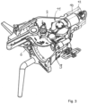
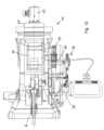
- FIG. 1 A decoupled position of the coupling head 1 or the coupling lock 3 is shown.
- Such a decoupled position which is also referred to as the ready-to-couple position, can also be the overdrawn position mentioned above.
- the dome closures 3 are loaded exclusively by tensile forces, whereas the compressive forces are transmitted via the end faces 23 of the end plate 24.
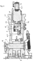
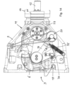
- the Figure 4 shows the arrangement from the Figure 3 again in a vertical section, but here without the coupling rod 10, which is connected in the axial direction to the coupling head housing 2.
- the electric motor 12 is connected in the drive connection to the frog 6 by a harmonic drive (or generally a reduction gear, in particular an eccentric gear or differential gear) 25, which carries a drive pinion 13 on the output side coaxial with the output rotational axis 12.1 of the electric motor, which drive pinion meshes with a crown gear 14 rotating about a vertical rotational axis 14.1 in order to drive the crown gear 14.
- the rotational axis 14.1 is parallel to the main axis 7, about which the main pin 19 can be rotated together with the frog 6.
- the output rotational axis 12.1 is arranged radially to the main axis 7.
- meshing bevel gears can also be considered to form a bevel gear
- the drive pinion 13 and the crown gear 14 together form an angular gear 15, which preferably has a reduction gear, as does the wave gear 25.
- the angular gear output 15.1 is formed by a rotary lever 17, which can be rotated about the angular gear output rotation axis 15.2.
- the angular gear output rotation axis 15.2 and the rotation axis 14.1 of the crown gear 14 coincide.
- the rotary lever 17 With the rotation of the crown gear 14, the rotary lever 17 is also rotated about the angular gear output rotation axis 15.2.
- the rotary lever 17 is connected to the frog 6 via an articulated lever 16, comprising a first lever part 16.1 and a second lever part 16.2.
- the first lever part 16.1 is articulated to the frog 6
- the second lever part 16.2 is articulated to the first lever part 16.1 and articulated to the rotary lever 17.
- the position of the rotary lever 17 can be detected, for example, by a sensor 18.
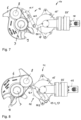
- the function of the electrically operated uncoupling device 11 will be explained below using the Figures 6 to 8 be explained.
- the frog 6 is shown in the uncoupled position; the angular gear output 15.1, which is formed by the rotary lever 17, is in its so-called zero position, in which it does not hinder rotation of the frog 6 about the main axis 7.
- the first lever part 16.1 and the second lever part 16.2 are folded against each other or moved towards each other, i.e., they enclose a comparatively acute angle between them.
- the angular gear output 15.1 can remain in its zero position, and the increasing distance between the connecting joint of the articulated lever 16 on the frog 6 and the connecting joint of the articulated lever 16 on the angular gear output 15.1 is bridged by folding apart the first lever part 16.1 and the second lever part 16.2. Accordingly, in the coupled position of the frog 6, the first lever part 16.1 and the second lever part 16.2 extend relatively linearly relative to one another.
- the angular gear output 15.1 or the rotary lever 17 is moved into the position shown in the Figure 8 shown release position by driving the electric motor 12. During this rotation, the rotary lever 17 pulls on the frog 6 via the articulated lever 16, so that it is rotated into the uncoupled position.
- the angle gear output 15.1 or the rotary lever 17 is turned again into its zero position, which is in the Figures 6 and 7 shown, preferably before the frog 6 begins to rotate into the coupled position.
- the Figure 9a shows the frog 6 in the coupled position and the angular gear output 15.1 in its zero position.
- the articulated lever 16 and the angular gear output 15.1 are designed differently from the embodiment shown in the previous figures.
- the articulated lever 16 is one-piece and is connected to the frog 6 in an articulated manner on the one hand and to the rotary lever 17 on the other hand.
- the rotary lever 17 on the angular gear output 15.1 is used to rotate the frog 6 from the position shown in the Figure 9a shown coupled position to the position shown in the Figure 9b shown uncoupled position by a Driver 34 is rotated in such a way that it pulls on the frog 6 via the articulated lever 16 to move it into the uncoupled position.
- angle gear output 15.1 is now returned to its zero position, which is in the Figures 9a and 9c shown, is rotated, this is done by turning back the driver 34, which is arranged non-rotatably on the angular gear output 15.1, so that it moves away from the rotary lever 17, which is arranged rotatably on the angular gear output 15.1, and, as shown in the Figure 9c As shown, a turning back of the frog 6 into the coupled position, during which turning back the rotary lever 17 must also be turned back via the articulated lever 16, is not blocked.
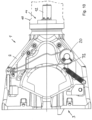
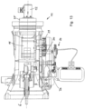
- FIG 10 A view from below of the coupling head housing 2 of an alternative design of an automatic train coupling is shown.
- the function of the automatic train coupling can be described in the Figure 1
- the coupling rod 10, which accommodates the electric motor 12, is shown in dashed lines.
- parts of the electrically actuated uncoupling device 11 are arranged in a separate housing 31 below the coupling head housing 2. This is particularly evident from the Figure 11 Below the housing 31, parts of the manual operating device 20 are provided, which is connected to the main bolt 19 at the bottom. The parts of the manual operating device 20 can also be seen from the illustration in the Figure 14 , in which the components of the electrically operated decoupling device 11 are also shown.
- the angular gear output 15.1 which is rotatable about the angular gear output rotation axis 15.2, carries a first spur gear 29, which is connected to a spur gear segment 30 meshes, which is connected to the main pin 19 in a torque-transmitting manner, at least in the direction of rotation of the frog 6 from the coupled position to the uncoupled position.
- a one-sided torque transmission can be achieved by a freewheel.
- this torque transmission is achieved by a driver 32, which is fixedly connected to the spur gear segment 30 (or a corresponding second spur gear) and drives the lever 33 of the manual actuation device 20 when the angular gear output 15.1 is rotated from its zero position to the release position.
- the lever 33 is accordingly connected to the main pin 19 in a rotationally fixed manner. In principle, however, the connection of this lever 33 or another lever, which is driven by the driver 32, to the frog 6 would also be possible.
- the driver 32 acts unilaterally, it is easy to reverse the angular gear 15 without simultaneously moving the frog 6 into its coupled position.
- the frog remains in the uncoupled position until the coupling lock 3 is moved into the coupled position by engaging an opposing train coupler or an opposing coupling lock.
- another motor can also be considered instead of the electric motor, for example a hydraulic motor or a pneumatic motor.
Landscapes
- Engineering & Computer Science (AREA)
- Mechanical Engineering (AREA)
- Mechanical Operated Clutches (AREA)
- Gear Transmission (AREA)
Description
- Die vorliegende Erfindung betrifft eine automatische Zugkupplung, insbesondere für einen Güterwagen eines Schienenfahrzeugs, gemäß dem Oberbegriff von Anspruch 1 und ein Verfahren zum Entkuppeln einer solchen automatischen Zugkupplung gemäß dem Oberbegriff von Anspruch 16.
- In der Praxis sind gattungsgemäße automatische Zugkupplungen bekannt, die einen Kupplungskopf mit einem Kupplungsgehäuse und einem Kuppelverschluss mit Arretierung aufweisen. Der Kuppelverschluss ist als Drehverschluss mit einer Kuppelöse und einem Herzstück ausgeführt, wobei das Herzstück um eine Hauptachse verdrehbar ist zwischen einer gekuppelten Stellung und einer entkuppelten Stellung, und die Kuppelöse mit einem ersten Ende verdrehbar um eine Kuppelösenachse am Herzstück angeschlossen ist und ein zweites freies Ende aufweist. Das Herzstück weist ein Maul zur Aufnahme eines entsprechenden zweiten Endes einer Kuppelöse eines gegengleichen Kupplungskopfes auf.
- Dem Herzstück ist ein Federspeicher zugeordnet. Das Herzstück ist entgegen der Kraft des Federspeichers aus der gekuppelten Stellung in die entkuppelte Stellung und durch die Kraft des Federspeichers aus der entkuppelten Stellung in die gekuppelte Stellung verdrehbar.
- Die entkuppelte Stellung wird auch als kuppelbereite Stellung bezeichnet, da in dieser Stellung die Zugkupplungen der beiden Wagen gegeneinander gefahren und gekuppelt werden können. Gegebenenfalls kann der Kuppelverschluss beziehungsweise dessen Herzstück auch in eine gegenüber der kuppelbereiten Stellung überzogene Stellung verdreht werden, also mehr als nötig geöffnet werden. In dieser überzogenen Stellung ist der Federspeicher maximal gespannt. Auch bei dieser überzogenen Stellung handelt es sich im Sinne der vorliegenden Erfindung um eine kuppelbereite oder entkuppelte Stellung. Ferner wird eine solche kuppelbereite oder entkuppelte Stellung auch als Warteposition bezeichnet.
- Die Arretierung, welche den Kuppelverschluss in der jeweils geeigneten Stellung hält oder entsprechend zum Übergang in eine andere Stellung durch Verdrehen des Herzstückes freigibt, weist zum Beispiel einen entgegen einer Federkraft in Kuppelrichtung der Zugkupplung verschiebbaren Stempel und eine quer oder schräg zur Kuppelrichtung verschiebbare Klinkenstange auf. Die Klinkenstange ist gelenkig am Herzstück angeschlossen und vom Herzstück bei dessen Verdrehung aus der gekuppelten Stellung in die entkuppelte Stellung in eine Rastposition verschiebbar, in welcher die Klinkenstange eine Verdrehung des Herzstückes zurück, das heißt in Richtung aus der entkuppelten Stellung in die gekuppelte Stellung, blockiert. Der Stempel wiederum ist bewegbar zwischen einer ersten Position und einer zweiten Position. In der ersten Position, in welcher der Stempel entgegen der Federkraft verschoben ist, blockiert der Stempel die Klinkenstange in der Rastposition und in der zweiten Position, in welche der Stempel durch die Federkraft aus der ersten Position verschoben wird, löst der Stempel die Klinkenstange aus der Rastposition.
- Die Funktion der gattungsgemäßen automatischen Zugkupplung ist wie folgt: Zwei gegengleiche Kupplungsköpfe an zwei miteinander zu kuppelnden Fahrzeugen werden dadurch aneinander arretiert, dass jeweils das zweite Ende der jeweiligen Kuppelöse in das Maul des Herzstückes des jeweils anderen Kupplungskopfes eingesetzt und durch Verdrehen des dortigen Herzstückes formschlüssig gehalten wird. Damit werden die beiden Fahrzeuge mechanisch miteinander gekuppelt. Die beiden Kuppelverschlüsse werden ausschließlich durch Zugkräfte belastet, die sich innerhalb des Parallelogramms, das die Kuppelösen und die Herzstücke bilden, auf beide Kuppelösen gleichmäßig verteilen. Druckkräfte hingegen werden durch ein besonderes Profil frontseitig am Kupplungskopfgehäuse übertragen, wobei das Profil in der Regel, wie vorteilhaft auch bei der vorliegenden Erfindung, einen Kegel und einen Trichter umfasst, die von einer breiten, insbesondere ebenen Stirnfläche umschlossen sind. Das Profil kann von einer separaten Stirnplatte gebildet werden, die vorne am Kupplungskopfgehäuse befestigt ist. Das Profil kann mit dem Kegel und Trichter Gleit- und Zentrierflächen bilden und insbesondere den Greifbereich in Seiten-, Höhen- und Winkelversatz bestimmen.
- Wenn die Kupplungsköpfe aufeinandertreffen, zentrieren sie sich und gleiten ineinander.
- Wenn zwei Schienenfahrzeuge aufeinander zu bewegt werden, so befinden sich deren Kuppelverschlüsse beziehungsweise deren Herzstücke in der kuppelbereiten beziehungsweise entkuppelten Stellung, in welcher die Herzstücke insbesondere von den Klinkenstangen, die sich in der Rastposition befinden, gehalten werden. Beim Kuppeln tauchen jeweils die Kegel in die Trichter der Kupplungskopfgehäuseprofile ein. Dabei drücken die Kegel auf die Stempel und schieben diese zurück, sodass die Stempel die Klinkenstangen aus deren Rastposition lösen. Dadurch werden die Kuppelverschlüsse freigegeben und durch die Kraft des jeweiligen Federspeichers gedreht, bis das Herzstück an einem vorgegebenen Anschlag, in der Regel am Kupplungskopfgehäuse, anschlägt. Dabei rasten die in den Trichtern geführten Kuppelösen in die Herzstückmäuler ein, die beiden Kuppelverschlüsse sind ineinander verhakt und die gekuppelte Stellung ist erreicht. Ein ungewolltes Trennen der Kuppelverschlüsse ist nicht möglich. Normaler Verschleiß beeinträchtigt die Sicherheit des Kuppelverschlusses nicht.
- Um die Kupplungsköpfe zu entkuppeln, dreht eine Entkuppeleinrichtung beide Kuppelverschlüsse, das heißt die beiden Herzstücke gegen die Kraft der Federspeicher, bis die Kuppelösen aus den Mäulern der Herzstücke gleiten. Die sich verdrehenden Herzstücke sollen dabei die Klinkenstangen soweit verschieben, dass beim Trennen der Fahrzeuge ein Zurückdrehen der Herzstücke aus der überzogenen Stellung über die kuppelbereite Stellung hinaus dadurch verhindert wird, dass die Klinkenstangen in ihre Rastpositionen verbracht werden.
- Entkuppeleinrichtungen sind in unterschiedlichen Ausführungen bekannt. Beispielsweise weisen manuell betätigbare, mechanische Entkuppeleinrichtungen Hebel, Seile und/oder Kettenzüge auf, die auf unterschiedliche Arten von Riegeln wirken und bei Betätigung die Riegelstellung aufheben. Automatisierte Entkuppeleinrichtungen umfassen als Antrieb einen pneumatischen Zylinder oder einen elektrischen Motor, insbesondere einen Linearaktuator, welcher die Zugkupplung entkuppelt. Beispielsweise offenbart
DE 29 23 195 C2 eine fernbetätigbare Entkuppeleinrichtung für eine Mittelpufferkupplung eines Schienenfahrzeugs, bei welcher ein Elektromotor über eine Kurvenscheibe eine am Hauptbolzen drehfest angeschlossenen Hebel betätigt, um das Herzstück aus der gekuppelten Stellung in die entkuppelte Stellung zu verdrehen.DE 40 13 521 A1 offenbart eine Kuppel- und Entkuppeleinrichtung für eine elektrische Kabelkupplung und eine mechanische Kupplung mit einem gemeinsamen Drehantrieb.EP 3 470 295 A1 offenbart einen elektrischen Linearaktuator, der über einen Hebel am Hauptbolzen angreift.EP 3 689 705 A1 beschreibt eine automatische Zugkupplung mit den Merkmalen des Oberbegriffs des Anspruchs 1. - Die bekannten automatisierten Entkuppeleinrichtungen benötigen einen relativ großen Bauraum und sind außen an der automatischen Zugkupplung außerhalb des Kupplungskopfgehäuses angeordnet. Um die Entkuppeleinrichtungen vor Umwelteinflüssen zu schützen, können Einhausungen vorgesehen werden, welche die Entkuppeleinrichtungen gegenüber der Umgebung abschirmen. Nachteilig an den bekannten Ausführungsformen ist der mit diesen Einhausungen verbundene konstruktive Aufwand und der damit erforderliche vergleichsweise große Bauraum.
- Ein weiterer Nachteil der bekannten automatischen Zugkupplungen liegt darin, dass nach einem Entkuppeln mit der Entkuppeleinrichtung das Herzstück ungewollt in seine gekuppelte Stellung verdreht werden kann, wenn das entsprechende Schienenfahrzeug, das die automatische Zugkupplung aufweist, im Rangierbetrieb verfahren wird. So besteht beispielsweise beim Abdrücken des Schienenfahrzeugs über einen Abrollberg bei der gerade entkuppelten automatischen Zugkupplung die Gefahr, dass diese wieder einkuppelt, bevor das Schienenfahrzeug auf den im Richtungsgleis vorgesehenen Wagen auffährt. Ein unbeabsichtigtes Einkoppeln erfordert, dass die Kupplung erneut entkuppelt wird, was mit einem zusätzlichen Zeitaufwand verbunden ist und das Rangieren stört.
- Der vorliegenden Erfindung liegt die Aufgabe zugrunde, eine automatische Zugkupplung, insbesondere für einen Güterwagen eines Schienenfahrzeugs, beispielsweise der vorstehend dargestellten Ausführungsform derart zu verbessern und ein Verfahren zum Entkuppeln einer automatischen Zugkupplung anzugeben, bei welchen die vorgenannten Nachteile vermieden werden.
- Die erfindungsgemäße Aufgabe wird durch eine automatische Zugkupplung mit den Merkmalen von Anspruch 1 und ein Verfahren mit den Merkmalen von Anspruch 16 gelöst. In den abhängigen Ansprüchen werden vorteilhafte und besonders zweckmäßige Ausgestaltungen der Erfindung sowie ein Schienenfahrzeug mit einer erfindungsgemäßen automatischen Zugkupplung angegeben.
- Die erfindungsgemäße automatische Zugkupplung, die insbesondere als automatische Zugkupplung eines Güterwagens eines Schienenfahrzeugs ausgeführt ist, weist einen Kupplungskopf auf, der ein Kupplungskopfgehäuse und einen Kuppelverschluss mit Arretierung umfasst. Arretierung bedeutet, dass der Kuppelverschluss zumindest in einer Stellung drehfest arretierbar ist, wie sich aus dem Nachfolgenden ergibt.
- Der Kuppelverschluss ist als Drehverschluss mit einer Kuppelöse und einem Herzstück ausgeführt, wobei das Herzstück um eine Hauptdrehachse verdrehbar ist zwischen einer gekuppelten Stellung und einer entkuppelten Stellung. Die Kuppelöse ist mit einem ersten Ende verdrehbar um eine Kuppelösenachse am Herzstück angeschlossen und weist ein zweites freies Ende auf.
- Das Herzstück weist ein Maul auf, das zur Aufnahme eines zweiten Endes einer Kuppelöse eines gegengleichen Kupplungskopfes angeordnet ist.
- Ferner ist eine elektrisch, hydraulisch oder pneumatisch betätigte Entkuppeleinrichtung vorgesehen, die einen Elektromotor, Hydaulikmotor oder pneumatischen Motor umfasst, der über eine Triebverbindung zumindest mittelbar am Herzstück angeschlossen ist, um das Herzstück aus der gekuppelten Stellung in die entkuppelte Stellung zu verdrehen.
- Mit der Arretierung kann das Herzstück insbesondere in der entkuppelten Stellung, der sogenannten kuppelbereiten Stellung, drehfest gehalten werden.
- Erfindungsgemäß weist die Entkuppeleinrichtung eine Sperrstellung auf, in der sie ein Verdrehen des Herzstücks aus der entkuppelten Stellung in die gekuppelte Stellung über die Triebverbindung blockiert, wobei eine Steuervorrichtung vorgesehen ist, mit welcher die Entkuppeleinrichtung ansteuerbar ist, um diese über eine Zeitspanne dauerhaft in der Sperrstellung zu halten. Die Dauer der Zeitspanne kann beispielsweise durch eine aktive Betätigung, insbesondere mittels eines Schalters, bestimmt werden, indem beispielsweise das Halten in der Sperrstellung dann beendet wird, wenn durch den Fahrzeugführer eine Freigabe erfolgt. Prinzipiell könnte auch eine vorbestimmte Zeitspanne ausgewählt werden, die dann automatisch beendet wird.
- Die erfindungsgemäße Entkuppeleinrichtung wirkt demnach durch den in ihr enthaltenen Motor und ist von der zuvor genannten Arretierung, die rein mechanisch durch gegenseitiges Anfahren von zwei automatischen Zugkupplungen wirkt, zu unterscheiden. Vielmehr ist die elektrisch, hydraulisch oder pneumatisch betätigte Entkuppeleinrichtung zusätzlich zu der mechanischen Arretierung vorgesehen.
- Bevorzugt ist die Entkuppeleinrichtung entweder vollständig innerhalb des Kupplungskopfgehäuses angeordnet, oder die Entkuppeleinrichtung ist vollständig innerhalb des Kupplungskopfgehäuses und einer sich an das Kupplungskopfgehäuse anschließenden Kupplungsstange angeordnet, also in einem Raum, der entweder allein vom Kupplungskopfgehäuse umschlossen wird oder der vom Kupplungskopfgehäuse zusammen mit einem entsprechenden Bereich der Kupplungsstange umschlossen wird.
- Durch eine solche Ausgestaltung kann auf zusätzliche Einhausungen für die elektrisch, hydraulisch oder pneumatisch betätigte Entkuppeleinrichtung verzichtet werden und zugleich kann ein guter Schutz der elektrisch, hydraulisch oder pneumatisch betätigten Entkuppeleinrichtung vor Umwelteinflüssen gewährleitstet werden. Außerhalb des Kupplungskopfgehäuses und gegebenenfalls des entsprechenden Teils der Kupplungsstange muss kein Bauraum für die elektrisch, hydraulisch oder pneumatisch betätigte Entkuppeleinrichtung vorgehalten werden.
- Eine andere bevorzugte Ausführungsform sieht vor, dass Teile der elektrisch, hydraulisch oder pneumatisch betätigte Entkuppeleinrichtung außerhalb des Kupplungskopfgehäuse und außerhalb der Kupplungsstange angeordnet sind, wobei andere Teile der Entkuppeleinrichtung bevorzugt innerhalb des Kupplungskopfgehäuses und/oder der Kupplungsstange angeordnet sind, zum Beispiel der Motor und insbesondere das nachfolgend noch erläuterte Wellgetriebe und/oder Winkelgetriebe. Die außerhalb des Kupplungskopfgehäuses angeordneten Teile können von einer zusätzlichen Einhausung umschlossen sein.
- Besonders kompakt kann die elektrisch, hydraulisch oder pneumatisch betätigte Entkuppeleinrichtung ausgeführt werden, wenn der Motor eine Abtriebsdrehachse aufweist, die zumindest im Wesentlichen radial zur Hauptachse angeordnet ist. Die Abtriebsdrehachse zeigt demnach vorteilhaft in Richtung der Hauptachse beziehungsweise schneidet die Hauptachse oder zumindest einen um die Hauptachse verdrehbaren Hauptbolzen, der drehfest am Herzstück angeschlossen ist. Im Vergleich zu einer Motorabtriebsdrehachse, die windschief oder tangential zu einem solchen Hauptbolzen oder zur Hauptachse angeordnet ist, benötigt die elektrisch, hydraulisch oder pneumatisch betätigte Entkuppeleinrichtung einen wesentlich schmaleren Bauraum, der sich mit seiner Längserstreckung in Richtung der Kupplungsstangenlängsachse beziehungsweise der Kupplungskopfgehäuselängsachse erstreckt und damit leicht innerhalb des Kupplungskopfgehäuses und ggf. dem angrenzenden Bereich der Kupplungsstange untergebracht werden kann.
- Günstig für die kompakte Ausführungsform ist, wenn in der Triebverbindung zwischen dem Motor, insbesondere dem Elektromotor und dem Herzstück ein Winkelgetriebe vorgesehen ist. Ein solches Winkelgetriebe kann beispielsweise durch ein Antriebsritzel und ein mit diesem in verzahnten Eingriff stehendes Kronenrad gebildet werden, dessen Drehachse parallel zur Hauptachse ist. Das Antriebsritzel kann auf der Abtriebsdrehachse beziehungsweise auf einer um die Abtriebsdrehachse umlaufender Abtriebswelle des Motors, insbesondere dem Elektromotor vorgesehen sein oder koaxial zu dieser angeordnet sein und in Triebverbindung mit der Abtriebswelle des Motors stehen. Das Antriebsritzel kann auch als Kegelrad ausgeführt sein, das mit einem weiteren Kegelrad anstelle des Kronenrads kämmt.
- Gemäß einer vorteilhaften Ausführungsform der Erfindung ist das Winkelgetriebe über einen einteiligen oder mehrteiligen Gelenkhebel am Herzstück angeschlossen. Insbesondere, wenn der Gelenkhebel einteilig ist, so kann am Winkelgetriebeabtrieb ein Mitnehmer, beispielsweise in Form eines Bolzens auf einer Scheibe, vorgesehen sein, der den Gelenkhebel beim Verdrehen des Herzstücks aus der gekuppelten Stellung in die entkuppelte Stellung mitnimmt und ein Verdrehen des Winkelgetriebeabtriebs in die entgegengesetzte Richtung ohne Mitnahme des Gelenkhebels ermöglicht.
- Gemäß einer anderen Ausführungsform ist das Winkelgetriebe über einen Gelenkhebel am Herzstück angeschlossen, der wenigstens zweiteilig ist, umfassend ein erstes Hebelteil, das gelenkig am Herzstück angeschlossen ist, und ein zweites Hebelteil, das gelenkig am ersten Hebelteil und gelenkig an einem Winkelgetriebeabtrieb angeschlossen ist, wobei die Drehachsen der genannten gelenkigen Anschlüsse parallel zur Hauptachse sind. Damit kann zum einen ein kompakter Bauraum erzielt werden und zum anderen kann die notwendige Bewegungsfreiheit bei der Verdrehung des Herzstücks erreicht werden, ohne die Gefahr einer unerwünschten Blockade oder Einschränkung durch das Winkelgetriebe.
- Der Winkelgetriebeabtrieb kann beispielsweise durch einen Drehhebel gebildet werden, der sich radial zur einer Winkelgetriebeabtriebsdrehachse erstreckt. Gemäß einer Ausführungsform ist ein solcher Winkelgetriebeabtrieb im Wesentlichen speichenförmig. Jedoch kommen auch ein scheibenförmiger oder kreisförmiger Winkelgetriebeabtrieb oder andere Formen in Betracht.
- Zwischen dem Winkelgetriebe und dem Motor kann gemäß einer vorteilhaften Ausführungsform der Erfindung ein Untersetzungsgetriebe, vorteilhaft mit einer koaxialen Anordnung von dessen Antrieb und Abtrieb vorgesehen sein. Das Winkelgetriebe kann zum Beispiel als Planetengetriebe oder Exzentergetriebe, insbesondere in Form eines Wellgetriebes, ausgeführt sein. Auch ein Differentialgetriebe kommt beispielsweise in Betracht. Der Abtrieb dieses Untersetzungsgetriebes wird dann insbesondere durch das genannte Antriebsritzel gebildet, welches den Eingang zu dem Winkelgetriebe darstellt.
- Das Untersetzungsgetriebe, insbesondere in Form des Wellgetriebes, kann dann koaxial zu dem Motor beziehungsweise zu dessen Abtriebsdrehachse angeordnet sein.
- Das Winkelgetriebe kann bevorzugt eine weitere Untersetzung aufweisen, um die Drehzahl in Richtung des Antriebsleistungsflusses hinter dem Winkelgetriebe nochmals zu reduzieren und bevorzugt zugleich das übertragene Drehmoment zu erhöhen. Damit kann ein besonders großes Drehmoment auf das Herzstück zum Verdrehen des Herzstücks aus seiner gekuppelten Stellung in die entkuppelte Stellung erreicht werden.
- Das Wellgetriebe und/oder das Winkelgetriebe können vom Motor oder von einer Konsole, die den Motor trägt und insbesondere plattenförmig ist, getragen werden, insbesondere ausschließlich.
- Bevorzugt ist der Winkelgetriebeabtrieb um eine Winkelgetriebeabtriebsdrehachse verdrehbar zwischen einer Nullstellung und einer Auslösestellung. In der Nullstellung ermöglicht der Winkelgetriebeabtrieb eine Verdrehung des Herzstücks zwischen der gekuppelten Stellung und der entkuppelten Stellung ohne eine Behinderung durch den Winkelgetriebeabtrieb. Beim Verdrehen des Winkelgetriebeabtriebs aus der Nullstellung in die Auslösestellung treibt der Winkelgetriebeabtrieb das Herzstück an, damit sich dieses aus der gekuppelten Stellung in die entkuppelte Stellung verdreht.
- Die Länge des Gelenkhebels, insbesondere die Längen des ersten Hebelteils und des zweiten Hebelteils, sind daher bevorzugt derart gewählt, dass das Herzstück aus der entkuppelten Stellung in die gekuppelte Stellung verdrehbar ist und dabei der Winkelgetriebeabtrieb in der Nullstellung verbleibt. Somit kann der Bogen, den die Drehachse des gelenkigen Anschlusses des zweiten Hebelteils am Winkelgetriebeabtrieb bei der Verdrehung des Winkelgetriebeabtriebs aus der Nullstellung in die Auslösestellung überstreicht, kleiner oder gleich der kombinierten Längen des ersten Hebelteils und des zweiten Hebelteils sein.
- Gemäß einer anderen Ausführungsform der Erfindung ist das Winkelgetriebe über einen Rädertrieb zumindest mittelbar an einem Hauptbolzen angeschlossen, der in einer Triebverbindung am Herzstück angeschlossen ist. Bei der Triebverbindung kann es sich um eine einseitig drehfeste Verbindung mit einem in die Gegenrichtung wirkenden Freilauf handeln, sodass das Herzstück mit der elektrisch, hydraulisch oder pneumatisch betätigbaren Entkuppeleinrichtung beziehungsweise mit deren Winkelgetriebe aus der gekuppelten Position in die entkuppelte Position verdrehbar ist, jedoch eine gegenläufige Betätigung des Winkelgetriebes ohne Drehmomentübertragung auf das Herzstück möglich ist, um ein Zurückdrehen des Herzstücks aus der entkuppelten Stellung in die gekuppelte Stellung freizugeben, wobei das Zurückdrehen dann jedoch wie herkömmlich über den Kuppelverschluss beziehungsweise das Zusammenfahren von zwei automatischen Zugkupplungen erfolgt. Alternativ ist gemäß einer bevorzugten Ausführungsform, die nachfolgend noch näher beschrieben wird, in einseitig wirkender Mitnehmer in der Triebverbindung zwischen dem Winkelgetriebe und dem Herzstück beziehungsweise dem Hauptbolzen vorgesehen, der die Entkuppelbewegung der Entkuppeleinrichtung auf das Herzstück überträgt und eine gegensinnige Bewegung der Entkuppeleinrichtung nicht auf das Herzstück weitergibt.
- Beispielsweise weist das Winkelgetriebe auch bei dieser Ausführungsform einen um eine Winkelgetriebeabtriebsdrehachse verdrehbaren Winkelgetriebeabtrieb auf, der parallel zur Hauptachse ist und auf dem ein erstes Stirnrad angeordnet ist, das mit einem zweiten Stirnrad oder einem Stirnradsegment kämmt, das in einer Triebverbindung mit dem Hauptbolzen steht, wobei der Winkelgetriebeabtrieb zwischen einer Nullstellung und einer Auslösestellung verdrehbar ist. Insbesondere wird bei einer Verdrehung des Winkelgetriebeabtriebs aus der Nullstellung in die Auslösestellung das Herzstück aus seiner gekuppelten Stellung in die entkuppelte Stellung verdreht, jedoch bei einem Zurückdrehen des Winkelgetriebeabtriebs aus seiner Auslösestellung in die Nullstellung die Verdrehung des Herzstücks aus der entkuppelten Stellung in die gekuppelte Stellung nur freigegeben, ohne dass sofort eine entsprechende Verdrehung des Herzstücks erfolgt.
- Besonders bevorzugt ist eine Handbetätigungsvorrichtung vorgesehen, mit welcher das Herzstück manuell in die entkuppelte Stellung und/oder der Winkelgetriebeabtrieb in die Nullstellung verbringbar ist. Durch Verbringen des Winkelgetriebeabtriebs in die Nullstellung wird ein Blockieren der Verdrehung des Herzstücks aus der gekuppelten Stellung in die entkuppelte Stellung vermieden. Durch ein Verdrehen des Herzstücks in die entkuppelte Stellung ist eine Entkupplung der automatischen Zugkupplung möglich.
- Bei einer sehr kompakten Ausführungsform, die zuverlässig arbeitete, weist das zweite Stirnrad oder Stirnradsegment einen Mitnehmer auf, der einen Hebel der Handbetätigungsvorrichtung, die am Hauptbolzen angreift, einseitig im Sinne eines Verdrehens des Herzstücks aus der gekuppelten Stellung in die entkuppelte Stellung beaufschlagt.
- Bevorzugt ist die Entkuppeleinrichtung unabhängig von der Stellung des Herzstücks betätigbar, und insbesondere ist der Winkelgetriebeabtrieb sowohl in der gekuppelten Stellung als auch in der entkuppelten Stellung des Herzstücks mit dem Motor um die Winkelgetriebeabtriebsdrehachse verdrehbar.
- Die Stellung der Entkuppeleinrichtung, insbesondere des Winkelgetriebeabtriebs und/oder des Gelenkhebels und/oder des zweiten Stirnrads oder Stirnradsegments, kann bevorzugt mit einem Sensor erfasst werden, um bestimmte Stellungen der Entkuppeleinrichtung überwachen zu können und/oder besser gezielt ansteuern zu können.
- Die automatische Zugkupplung kann, wie eingangs dargelegt, mit einer Arretierung versehen sein, die insbesondere die dargestellte Klinkenstange und den Stempel umfasst und wie eingangs beschrieben wurde arbeitet.
- Ein erfindungsgemäßes Schienenfahrzeug weist eine entsprechende automatische Zugkupplung der dargestellten Art auf.
- Ein erfindungsgemäßes Verfahren zum Entkuppeln einer automatischen Zugkupplung sieht vor, dass das Herzstück über die Triebverbindung zwischen der elektrisch, hydraulisch oder pneumatisch betätigten Entkuppeleinrichtung und dem Herzstück durch Antreiben des Motors mit der elektrisch, hydraulisch oder pneumatisch betätigten Entkuppeleinrichtung aus der gekuppelten Stellung in die entkuppelte Stellung verdreht wird. In einem vorwählbaren Betriebsmodus wird die Entkuppeleinrichtung in der Sperrstellung gehalten und so mit der Entkuppeleinrichtung ein Verdrehen des Herzstücks aus der entkuppelten Stellung in die gekuppelte Stellung blockiert.
- Bevorzugt kann die automatische Zugkupplung in zwei verschiedenen Betriebsmodi betrieben werden, wobei ein erster Betriebsmodus mit der Steuervorrichtung einstellbar ist, in welchem die Entkuppeleinrichtung unmittelbar nach Verdrehen des Herzstücks mit der Entkuppeleinrichtung aus der gekuppelten in die entkuppelte Stellung ein Verdrehen des Herzstücks aus der entkuppelten Stellung in die gekuppelte Stellung wieder freigibt, insbesondere durch Verdrehen des Winkelgetriebeabtriebs aus der Auslösestellung in die Nullstellung, und ein zweiter Betriebsmodus mit der Steuervorrichtung einstellbar ist, in welchem die Entkuppeleinrichtung in der Sperrstellung gehalten wird, wie dargelegt.
- Die Erfindung soll nachfolgend anhand eines Ausführungsbeispiels und den Figuren exemplarisch beschrieben werden.
- Es zeigen:
- Figur 1
- eine Schnittdarstellung einer erfindungsgemäßen automatischen Zugkupplung;
- Figur 2
- eine Ansicht einer erfindungsgemäßen automatischen Zugkupplung von unten;
- Figur 3
- eine teilweise geschnittene Ansicht einer erfindungsgemäßen automatischen Zugkupplung in einer Draufsicht schräg von oben;
- Figur 4
- einen Vertikalschnitt durch eine erfindungsgemäße automatische Zugkupplung;
- Figur 5
- eine erfindungsgemäße automatische Zugkupplung ohne das Kupplungskopfgehäuse in einer Ansicht schräg von oben;
- Figur 6
- die automatische Zugkupplung aus der
Figur 5 mit dem Herzstück in der entkuppelten beziehungsweise kuppelbereiten Stellung; - Figur 7
- die automatische Zugkupplung aus der
Figur 6 mit dem Herzstück in der gekuppelten Stellung; - Figur 8
- die automatische Zugkupplung aus den
Figuren 6 und7 in der entkuppelten Stellung und dem Winkelgetriebeabtrieb in der Auslösestellung; - Figuren 9a
- eine alternative Gestaltung des Winkelgetriebeabtriebs und des
- bis 9c
- Gelenkhebels mit dem Herzstück in der gekuppelten Stellung und entkuppelten Stellung und dem Winkelgetriebeabtrieb in der Auslösestellung und Nullstellung;
- Figur 10
- eine alternative Ausgestaltung einer automatischen Zugkupplung in einer Ansicht von unten;
- Figur 11
- einen Vertikalschnitt durch die alternative Ausgestaltung der automatischen Zugkupplung;
- Figur 12
- eine Ansicht schräg von unten auf die alternative Ausgestaltung der automatischen Zugkupplung;
- Figur 13
- eine schematische seitliche Ansicht der alternativen Ausgestaltung der automatischen Zugkupplung;
- Figur 14
- eine weitere Ansicht von unten auf die alternative Ausgestaltung der automatischen Zugkupplung mit Bauteilen des Gehäuses in gestrichelter Liniendarstellung.
- In der
Figur 1 ist schematisch ein Ausführungsbeispiel einer erfindungsgemäßen automatischen Zugkupplung in einer entkuppelten Stellung des Kuppelverschlusses 3 beziehungsweise von dessen Herzstück 6 gezeigt. Die zugehörige Entkuppeleinrichtung ist aus denFiguren 3 bis 8 entnehmbar. Im Einzelnen weist die automatische Zugkupplung einen Kupplungskopf 1 auf, der ein Kupplungskopfgehäuse 2 sowie den Kuppelverschluss 3 umfasst. Der Kuppelverschluss 3 ist als Drehverschluss ausgeführt, mit dem Herzstück 6, an welchem eine Kuppelöse 5 verdrehbar um eine Kuppelösenachse 8 angeschlossen ist. Das Herzstück 6 wiederum ist drehbar um die Hauptachse 7. Hierzu ist das Herzstück 6 auf einem Hauptbolzen 19 gelagert und drehfest an diesem angeschlossen. - Am Hauptbolzen 19 kann, wie in der
Figur 1 dargestellt ist, zum einen eine Handbetätigungsvorrichtung 20 angreifen, um den Kuppelverschluss 3 manuell zu entkuppeln. Zum anderen kann über den Hauptbolzen 19 ein Aktuator eines hier nicht näher dargestellten Ventils einer Druckluftleitung, insbesondere Bremsluftleitung HL, angesteuert werden, sodass beim Verdrehen des Kuppelverschlusses 3 in die gekuppelte Stellung das Ventil geöffnet wird und beim Verdrehen des Kuppelverschlusses 3 in die entkuppelte Stellung das Ventil geschlossen wird. - Die Kuppelöse 5 weist ein erstes Ende 5.1 auf, an welchem sie drehbar an dem Herzstück 6 angeschlossen ist, sowie ein entgegengesetztes zweites Ende 5.2, das in ein Maul 9 des Herzstücks 6 eines gegengleichen Kupplungskopfes 1 eingespannt werden kann, um die beiden Kupplungsköpfe 1 mechanisch aneinander zu verriegeln. Entsprechend weist die Kuppelöse 5 an ihrem zweiten Ende 5.2 einen hier nicht näher dargestellten Querriegel auf.
- Das Herzstück 6 jedes Kupplungskopfes 1 ist entgegen der Kraft eines Federspeichers 4, der beispielsweise durch eine oder mehrere Zugfedern gebildet wird, aus der entkuppelten Stellung in die gekuppelte Stellung verdrehbar.
- In der
Figur 1 ist eine entkuppelte Stellung des Kupplungskopfes 1 beziehungsweise des Kuppelverschlusses 3 gezeigt. Bei einer solchen entkuppelten Stellung, die auch als kuppelbereite Stellung bezeichnet wird, kann es sich auch im die eingangs genannte überzogene Stellung handeln. - Wenn in der in der
Figur 1 gezeigten entkuppelten Stellung des Kuppelverschlusses beziehungsweise des Herzstücks 6 zwei Kupplungsköpfe 1 aufeinander zubewegt werden, so tauchen die Kegel 21 in die Trichter 22 ein und entriegeln die Arretierung des Kuppelverschlusses 3, beispielsweise indem die Kegel 21 auf die Stempel 26 der Arretierung drücken, dabei eine Rastverbindung beispielsweise der Klinkenstangen 27 lösen, sodass die Herzstücke 6 nicht länger gegen ein Verdrehen in die gekuppelte Stellung blockiert werden und durch die Kraft beispielsweise des Federspeichers 4 sich in die gekuppelte Stellung verdrehen. Dabei rasten die in den Trichtern 22 geführten Kuppelösen 5 in die Herzstückmäuler 9 ein und die beiden Kuppelverschlüsse 3 sind ineinander verhakt. - Die Kuppelverschlüsse 3 werden ausschließlich durch Zugkräfte belastet, wohingegen die Druckkräfte über die Stirnflächen 23 der Stirnplatte 24 übertragen werden.
- Bei der Darstellung in der
Figur 2 erkennt man, dass alle Komponenten des Kuppelverschlusses 3 innerhalb des Kupplungskopfgehäuses 2 aufgenommen sind und sich in Längsrichtung der Zugkupplung an das Kupplungskopfgehäuse 2 die Kupplungsstange 10 anschließt, welche zusätzlich zu dem Kupplungskopfgehäuse 2 einen Teil der elektrisch betätigten Entkuppeleinrichtung 11, hier den Elektromotor 12, aufnimmt. - Die Aufnahme der kompletten, elektrisch betätigten Entkuppeleinrichtung 11 innerhalb des Kupplungskopfgehäuses 2 und dem sich anschließenden Bereich der Kupplungsstange 10 ergibt sich auch aus der
Figur 3 , welche einen Horizontalschnitt durch das Kupplungskopfgehäuse 2 und den sich anschließenden Bereich der Kupplungsstange 10 zeigt. Bei der Stellung in derFigur 3 befindet sich das Herzstück 6 dabei in der gekuppelten Stellung, in welcher das Maul 9 vergleichsweise weit innerhalb des Kupplungskopfgehäuses 2 angeordnet ist. - Die
Figur 4 zeigt die Anordnung aus derFigur 3 nochmals in einem Vertikalschnitt, hier jedoch ohne die Kupplungsstange 10, die sich in Axialrichtung an das Kupplungskopfgehäuse 2 anschließt. Besonders aus derFigur 4 ist ersichtlich, dass sich an den Elektromotor 12 in der Triebverbindung zum Herzstück 6 zunächst ein Wellgetriebe (oder allgemein Untersetzungsgetriebe, insbesondere Exzentergetriebe oder Differentialgetriebe) 25 anschließt, das abtriebsseitig koaxial zur Abtriebsdrehachse 12.1 des Elektromotors ein Antriebsritzel 13 trägt, das mit einem um eine vertikale Drehachse 14.1 umlaufenden Kronenrad 14 kämmt, um das Kronenrad 14 anzutreiben. Die Drehachse 14.1 ist parallel zur Hauptachse 7, um welche der Hauptbolzen 19 zusammen mit dem Herzstück 6 verdrehbar ist. Die Abtriebsdrehachse 12.1 ist radial zur Hauptachse 7 angeordnet. Anstelle des Antriebsritzels 13 und des Kronenrads 14 kommen beispielsweise auch miteinander kämmende Kegelräder in Betracht, um ein Kegelradgetriebe auszubilden - Das Antriebsritzel 13 und das Kronenrad 14 (oder die Kegelräder) bilden gemeinsam ein Winkelgetriebe 15, das bevorzugt eine Untersetzung aufweist, ebenso wie das Wellgetriebe 25.
- Die Anordnung des Elektromotors 12, des Wellgetriebes 25 und des Winkelgetriebes 15 ist auch nochmals aus der
Figur 5 entnehmbar. - Der Winkelgetriebeabtrieb 15.1 wird durch einen Drehhebel 17 gebildet, der um die Winkelgetriebeabtriebsdrehachse 15.2 verdrehbar ist. Im gezeigten Ausführungsbeispiel fallen die Winkelgetriebeabtriebsdrehachse 15.2 und die Drehachse 14.1 des Kronenrads 14 zusammen.
- Mit der Verdrehung des Kronenrads 14 wird auch der Drehhebel 17 um die Winkelgetriebeabtriebsdrehachse 15.2 verdreht. Der Drehhebel 17 ist über einen Gelenkhebel 16, umfassend ein erstes Hebelteil 16.1 und ein zweites Hebelteil 16.2, am Herzstück 6 angeschlossen. Das erste Hebelteil 16.1 ist gelenkig am Herzstück 6 angeschlossen, das zweite Hebelteil 16.2 ist gelenkig am ersten Hebelteil 16.1 und gelenkig am Drehhebel 17 angeschlossen.
- Die Position des Drehhebels 17 kann beispielsweise durch einen Sensor 18 erfasst werden.
- Die Funktion der elektrisch betätigten Entkuppeleinrichtung 11 soll nachfolgend anhand der
Figuren 6 bis 8 erläutert werden. In derFigur 6 ist das Herzstück 6 in der entkuppelten Stellung gezeigt, der Winkelgetriebeabtrieb 15.1, der durch den Drehhebel 17 gebildet wird, befindet sich in seiner sogenannten Nullstellung, in welcher er ein Verdrehen des Herzstücks 6 um die Hauptachse 7 nicht behindert. Das erste Hebelteil 16.1 und das zweite Hebelteil 16.2 sind gegeneinander eingeklappt oder aneinander angefahren, das heißt sie schließen einen vergleichsweise spitzen Winkel zwischen sich ein. - Wenn nun das Herzstück 6 aus der gezeigten entkuppelten Stellung in der
Figur 6 in die in derFigur 7 gezeigte gekuppelte Stellung verdreht wird, kann der Winkelgetriebeabtrieb 15.1 in seiner Nullstellung verbleiben und die sich vergrößernde Distanz zwischen dem Anschlussgelenk des Gelenkhebels 16 am Herzstück 6 und dem Anschlussgelenk des Gelenkhebels 16 am Winkelgetriebeabtrieb 15.1 wird durch Auseinanderklappen des ersten Hebelteils 16.1 und des zweiten Hebelteils 16.2 überbrückt. Demnach erstrecken sich in der gekuppelten Stellung des Herzstücks 6 das erste Hebelteil 16.1 und das zweite Hebelteil 16.2 vergleichsweise linear zueinander. - Um nun mit der elektrisch betätigten Entkuppeleinrichtung 11 das Herzstück aus der gekuppelten Stellung in die entkuppelte Stellung um die Hauptachse 7 zu verdrehen und damit den Kuppelverschluss 3 zu entkuppeln, wird der Winkelgetriebeabtrieb 15.1 beziehungsweise der Drehhebel 17 in die in der
Figur 8 gezeigte Auslösestellung durch Antrieb mit dem Elektromotor 12 verdreht. Bei dieser Verdrehung zieht der Drehhebel 17 über den Gelenkhebel 16 am Herzstück 6, sodass dieses in die entkuppelte Stellung verdreht wird. - Um nun ein erneutes Kuppeln des Kuppelverschlusses 3 zu ermöglichen, wofür das Herzstück 6 in die gekuppelte Stellung verdreht werden muss, wird der Winkelgetriebeabtrieb 15.1 beziehungsweise der Drehhebel 17 erneut in seine Nullstellung verdreht, die in den
Figuren 6 und7 gezeigt ist, bevorzugt bevor das Herzstück 6 beginnt, sich in die gekuppelte Stellung zu verdrehen. - Die
Figur 9a zeigt das Herzstück 6 in der gekuppelten Stellung und den Winkelgetriebeabtrieb 15.1 in seiner Nullstellung. Der Gelenkhebel 16 und der Winkelgetriebeabtrieb 15.1 sind dabei abweichend zu der in den vorherigen Figuren gezeigten Ausführungsform gestaltet. So ist der Gelenkhebel 16 einteilig und einerseits gelenkig am Herzstück 6 und andererseits gelenkig am Drehhebel 17 angeschlossen. Der Drehhebel 17 am Winkelgetriebeabtrieb 15.1 wird zum Verdrehen des Herzstücks 6 aus der in derFigur 9a gezeigten gekuppelten Stellung in die in derFigur 9b gezeigte entkuppelte Stellung durch einen Mitnehmer 34 derart verdreht, dass er über den Gelenkhebel 16 am Herzstück 6 zieht, um dieses in die entkuppelte Stellung zu bewegen. Wenn nun der Winkelgetriebeabtrieb 15.1 zurück in seine Nullstellung, die in denFiguren 9a und 9c gezeigt ist, gedreht wird, so erfolgt dies durch Rückdrehen des Mitnehmers 34, der drehfest am Winkelgetriebeabtrieb 15.1 angeordnet ist, sodass sich dieser vom Drehhebel 17, der verdrehbar am Winkelgetriebeabtrieb 15.1 angeordnet ist, entfernt und, wie in derFigur 9c gezeigt ist, ein Zurückdrehen des Herzstücks 6 in die gekuppelte Stellung, bei welchem Zurückdrehen auch der Drehhebel 17 über den Gelenkhebel 16 zurückgedreht werden muss, nicht blockiert. - In der
Figur 10 ist eine Ansicht von unten auf das Kupplungskopfgehäuse 2 einer alternativen Gestaltung einer automatischen Zugkupplung gezeigt. Die Funktion der automatischen Zugkupplung kann entsprechend der Beschreibung zu derFigur 1 sein. Die Kupplungsstange 10, welche den Elektromotor 12 aufnimmt, ist in gestrichelter Linie gezeigt. - Anders als im vorherigen Ausführungsbeispiel sind Teile der elektrisch betätigbaren Entkuppeleinrichtung 11 in einer separaten Einhausung 31 unterhalb des Kupplungskopfgehäuses 2 angeordnet. Dies ist besonders auch aus der
Figur 11 ersichtlich. Unterhalb der Einhausung 31 sind Teile der Handbetätigungsvorrichtung 20 vorgesehen, die unten am Hauptbolzen 19 angeschlossen ist. Die Teile der Handbetätigungsvorrichtung 20 ergeben sich auch aus der Darstellung in derFigur 14 , in der auch die Bauteile der elektrisch betätigten Entkuppeleinrichtung 11 gezeigt sind. - Die in den
Figuren 10 bis 14 gezeigte alternative Ausführungsform unterscheidet sich durch die Gestaltung der elektrisch betätigten Entkuppeleinrichtung 11 von der zuvor anhand derFiguren 2 bis 8 erläuterten Ausführungsform. Ausgehend vom Elektromotor 12 bis zum Kronenrad 14 entsprechen sich die Ausführungsformen jedoch. - Der Winkelgetriebeabtrieb 15.1, der um die Winkelgetriebeabtriebsdrehachse 15.2 verdrehbar ist, trägt ein erstes Stirnrad 29, das mit einem Stirnradsegment 30 kämmt, das zumindest in Drehrichtung des Herzstücks 6 aus der gekuppelten Stellung in die entkuppelte Stellung drehmomentübertragend am Hauptbolzen 19 angeschlossen ist. Eine solche einseitige Drehmomentübertragung kann durch einen Freilauf erreicht werden. Im gezeigten Ausführungsbeispiel wird diese Drehmomentübertragung durch einen Mitnehmer 32 erzielt, der ortsfest am Stirnradsegment 30 (oder einem entsprechenden zweiten Stirnrad) angeschlossen ist und den Hebel 33 der Handbetätigungsvorrichtung 20 mitnimmt, wenn der Winkelgetriebeabtrieb 15.1 aus seiner Nullstellung in die Auslösestellung verdreht wird. Der Hebel 33 ist entsprechend drehfest am Hauptbolzen 19 angeschlossen. Prinzipiell wäre jedoch auch der Anschluss dieses Hebels 33 oder eines anderen Hebels, der vom Mitnehmer 32 mitgenommen wird, am Herzstück 6 möglich.
- Da der Mitnehmer 32 einseitig wirkt, ist ohne weiteres ein Rückdrehen des Winkelgetriebes 15 möglich, ohne dass gleichzeitig das Herzstück 6 in seine gekuppelte Stellung bewegt wird. Somit verbleibt das Herzstück in der entkuppelten Stellung bis der Kuppelverschluss 3 durch Anfahren einer gegengleichen Zugkupplung beziehungsweise eines gegengleichen Kuppelverschlusses in die gekuppelte Stellung verbracht wird.
- Im Übrigen wird bezüglich der Funktionsweise der automatischen Zugkupplung beziehungsweise der elektrisch betätigten Entkuppeleinrichtung 11 auf die Beschreibung der
Figuren 1 bis 9 verwiesen. - Obwohl die Erfindung anhand eines Ausführungsbeispiels in vorteilhafter Weise mit Elektromotor dargestellt wurde, kommt anstelle des Elektromotors auch ein anderer Motor in Betracht, beispielsweise Hydraulikmotor oder pneumatischer Motor.
-
- 1
- Kupplungskopf
- 2
- Kupplungskopfgehäuse
- 3
- Kuppelverschluss
- 4
- Federspeicher
- 5
- Kuppelöse
- 5.1
- erstes Ende
- 5.2
- zweites Ende
- 6
- Herzstück
- 7
- Hauptachse
- 8
- Kuppelösenachse
- 9
- Maul
- 10
- Kupplungsstange
- 11
- elektrisch betätigte Entkuppeleinrichtung
- 12
- Elektromotor
- 12.1
- Abtriebsdrehachse
- 13
- Antriebsritzel
- 14
- Kronenrad
- 14.1
- Drehachse
- 15
- Winkelgetriebe
- 15.1
- Winkelgetriebeabtrieb
- 15.2
- Winkelgetriebeabtriebsdrehachse
- 16
- Gelenkhebel
- 16.1
- erstes Hebelteil
- 16.2
- zweites Hebelteil
- 17
- Drehhebel
- 18
- Sensor
- 19
- Hauptbolzen
- 20
- Handbetätigungsvorrichtung
- 21
- Kegel
- 22
- Trichter
- 23
- Stirnfläche
- 24
- Stirnplatte
- 25
- Wellgetriebe
- 26
- Stempel
- 27
- Klinkenstange
- 28
- Steuervorrichtung
- 29
- erstes Stirnrad
- 30
- Stirnradsegment
- 31
- Einhausung
- 32
- Mitnehmer
- 33
- Hebel
- 34
- Mitnehmer
Claims (17)
- Automatische Zugkupplung, insbesondere für einen Güterwagen eines Schienenfahrzeugs,mit einem Kupplungskopf (1), der ein Kupplungskopfgehäuse (2) und einen Kuppelverschluss (3) mit Arretierung umfasst, wobeider Kuppelverschluss (3) als Drehverschluss mit einer Kuppelöse (5) und einem Herzstück (6) ausgeführt ist, wobei das Herzstück (6) um eine Hauptachse (7) verdrehbar ist zwischen einer gekuppelten Stellung und einer entkuppelten Stellung, die Kuppelöse (5) mit einem ersten Ende (5.1) verdrehbar um eine Kuppelösenachse (8) am Herzstück (6) angeschlossen ist und ein zweites freies Ende (5.2) aufweist; unddas Herzstück (6) ein Maul (9) aufweist, das zur Aufnahme eines zweiten Endes (5.2) einer Kuppelöse (5) eines gegengleichen Kupplungskopfes (1) angeordnet ist;mit einer elektrisch, hydraulisch oder pneumatisch betätigten Entkuppeleinrichtung (11), die einen Elektromotor (12) oder Hydraulikmotor oder pneumatischen Motor umfasst, der über eine Triebverbindung zumindest mittelbar am Herzstück (6) angeschlossen ist, um das Herzstück (6) aus der gekuppelten Stellung in die entkuppelte Stellung zu verdrehen; dadurch gekennzeichnet, dassdie Entkuppeleinrichtung (11) eine Sperrstellung aufweist, in der sie ein Verdrehen des Herzstücks (6) aus der entkuppelten Stellung in die gekuppelte Stellung über die Triebverbindung blockiert, wobei eine Steuervorrichtung (28) vorgesehen ist, mit welcher die Entkuppeleinrichtung (11) ansteuerbar ist, um diese über eine Zeitspanne dauerhaft in der Sperrstellung zu halten.
- Automatische Zugkupplung gemäß Anspruch 1, dadurch gekennzeichnet, dass der Motor, insbesondere Elektromotor (12), eine Abtriebsdrehachse (12.1) aufweist, die zumindest im Wesentlichen radial zur Hauptachse (7) angeordnet ist.
- Automatische Zugkupplung gemäß einem der Ansprüche 1 oder 2, dadurch gekennzeichnet, dass in der Triebverbindung zwischen dem Motor, insbesondere Elektromotor (12), und dem Herzstück (6) ein Winkelgetriebe (15) vorgesehen ist.
- Automatische Zugkupplung gemäß Anspruch 3, dadurch gekennzeichnet, dass die Abtriebsdrehachse (12.1) ein Antriebsritzel (13) aufweist oder koaxial zu diesem und dieses antreibend angeordnet ist, welches in einem verzahnten Eingriff mit einem Kronenrad (14) oder Kegelrad steht, dessen Drehachse (14.1) parallel zur Hauptachse (7) ist, um das Winkelgetriebe (15) auszubilden.
- Automatische Zugkupplung gemäß einem der Ansprüche 3 oder 4, dadurch gekennzeichnet, dass zwischen dem Motor, insbesondere Elektromotor (12), und dem Winkelgetriebe (15) ein Untersetzungsgetriebe, insbesondere in Form eines koaxial zur Abtriebsdrehachse (12.1) angeordneten Exzentergetriebes, insbesondere Wellgetriebes (25), angeordnet ist.
- Automatische Zugkupplung gemäß einem der Ansprüche 3 bis 5, dadurch gekennzeichnet, dass das Winkelgetriebe (15) über einen Gelenkhebel (16) am Herzstück (6) angeschlossen ist, wobei der Gelenkhebel (16) wenigstens zweiteilig ist, umfassend ein erstes Hebelteil (16.1), das gelenkig am Herzstück (6) angeschlossen ist, und ein zweites Hebelteil (16.2), das gelenkig am ersten Hebelteil (16.1) und gelenkig an einem Winkelgetriebeabtrieb (15.1) angeschlossen ist, wobei die Drehachsen der gelenkigen Anschlüsse parallel zur Hauptachse (7) sind.
- Automatische Zugkupplung gemäß Anspruch 6, dadurch gekennzeichnet, dass der Winkelgetriebeabtrieb (15.1) durch einen Drehhebel (17) gebildet wird, der sich radial zu einer Winkelgetriebeabtriebsdrehachse (15.2) erstreckt.
- Automatische Zugkupplung gemäß einem der Ansprüche 3 bis 5, dadurch gekennzeichnet, dass das Winkelgetriebe (15) über einen Gelenkhebel (16) am Herzstück (6) angeschlossen ist, wobei der Gelenkhebel (16) einteilig oder mehrteilig ist und der Winkelgetriebeabtrieb (15) einen Mitnehmer (34) und einen Drehhebel (17) umfasst, der Drehhebel (17) gelenkig am Gelenkhebel (16) angeschlossen ist und mit dem Mitnehmer (34) in Wirkverbindung steht, um den Drehhebel (17) zur Verdrehung des Herzstücks (6) aus der gekuppelten Stellung in die entkuppelte Stellung mitzunehmen und ein Verdrehen des Winkelgetriebeabtriebs (15.1) in die hierzu entgegengesetzte Richtung den Drehhebel (17) freizugeben.
- Automatische Zugkupplung gemäß einem der Ansprüche 6 bis 8, dadurch gekennzeichnet, dass der Winkelgetriebeabtrieb (15.1) um eine Winkelgetriebeabtriebsdrehachse (15.2) verdrehbar ist zwischen einer Nullstellung und einer Auslösestellung, und die Länge des Gelenkhebels (16), insbesondere die Längen des ersten Hebelteils (16.1) und des zweiten Hebelteils (16.2), derart gewählt sind, dass das Herzstück (6) aus der entkuppelten Stellung in die gekuppelte Stellung verdrehbar ist und dabei der Winkelgetriebeabtrieb (15.1) in der Nullstellung verbleibt.
- Automatische Zugkupplung gemäß einem der Ansprüche 3 bis 5, dadurch gekennzeichnet, dass das Winkelgetriebe (15) über einen Rädertrieb zumindest mittelbar an einem Hauptbolzen (19) angeschlossen ist, der in einer Triebverbindung am Herzstück (6) angeschlossen ist.
- Automatische Zugkupplung gemäß Anspruch 10, dadurch gekennzeichnet, dass das Winkelgetriebe (15) einen um eine Winkelgetriebeabtriebsdrehachse (15.2) verdrehbaren Winkelgetriebeabtrieb (15.1) aufweist, der parallel zur Hauptachse (7) ist und auf dem ein erstes Stirnrad (29) angeordnet ist, das mit einem zweiten Stirnrad oder einem Stirnradsegment (30) kämmt, das in einem Drehantrieb mit dem Hauptbolzen (19) steht, wobei der Winkelgetriebeabtrieb (15.1) zwischen einer Nullstellung und einer Auslösestellung verdrehbar ist.
- Automatische Zugkupplung gemäß einem der Ansprüche 1 bis 11, dadurch gekennzeichnet, dass eine Handbetätigungsvorrichtung (20) vorgesehen ist, mit welcher das Herzstück (6) manuell in die entkuppelte Stellung und/oder der Winkelgetriebeabtrieb (15.1) in die Nullstellung verbringbar ist.
- Automatische Zugkupplung gemäß den Ansprüchen 11 und 12, dadurch gekennzeichnet, dass das zweite Stirnrad oder Stirnradsegment (30) einen Mitnehmer (32) aufweist, der einen Hebel (33) der Handbetätigungsvorrichtung (20), die am Hauptbolzen (19) angreift, einseitig im Sinne eines Verdrehens des Herzstücks (6) aus der gekuppelten Stellung in die entkuppelte Stellung beaufschlagt.
- Automatische Zugkupplung gemäß einem der Ansprüche 1 bis 13, dadurch gekennzeichnet, dass wenigstens ein Sensor (18) vorgesehen ist, der eine Stellung der Entkuppeleinrichtung (11), insbesondere des Winkelgetriebeabtriebs (15.1) und/oder des Gelenkhebels (16) und/oder des zweiten Stirnrads oder Stirnradsegments (30), erfasst.
- Schienenfahrzeug mit einer automatischen Zugkupplung gemäß einem der Ansprüche 1 bis 14.
- Verfahren zum Entkuppeln einer automatischen Zugkupplung gemäß einem der Ansprüche 1 bis 15, wobei das Herzstück (6) über die Triebverbindung durch Antreiben des Motors, insbesondere Elektromotors (12), mit der elektrisch, hydraulisch oder pneumatisch betätigten Entkuppeleinrichtung (11) aus der gekuppelten Stellung in die entkuppelte Stellung verdreht wird, dadurch gekennzeichnet, dass
in einem vorwählbaren Betriebsmodus die Entkuppeleinrichtung (11) in der Sperrstellung gehalten wird und mit der Entkuppeleinrichtung (11) ein Verdrehen des Herzstücks (6) aus der entkuppelten Stellung in die gekuppelte Stellung blockiert wird. - Verfahren gemäß Anspruch 16, dadurch gekennzeichnet, dass ein erster Betriebsmodus mit der Steuervorrichtung (28) einstellbar ist, in welchem die Entkuppeleinrichtung (11) unmittelbar nach dem Verdrehen des Herzstücks (6) mit der Entkuppeleinrichtung (11) aus der gekuppelten Stellung in die entkuppelte Stellung ein Verdrehen des Herzstücks (6) aus der entkuppelten Stellung in die gekuppelte Stellung wieder freigibt, insbesondere durch Verdrehen des Winkelgetriebeabtriebs (15.1) aus der Auslösestellung in die Nullstellung, und ein zweiter Betriebsmodus mit der Steuervorrichtung (28) einstellbar ist, in welchem die Entkuppeleinrichtung (11) in der Sperrstellung gehalten wird.
Applications Claiming Priority (3)
| Application Number | Priority Date | Filing Date | Title |
|---|---|---|---|
| DE102020133503 | 2020-12-15 | ||
| DE102021105364 | 2021-03-05 | ||
| PCT/EP2021/085650 WO2022129021A1 (de) | 2020-12-15 | 2021-12-14 | Automatische zugkupplung und verfahren zum entkuppeln einer automatischen zugkupplung |
Publications (2)
| Publication Number | Publication Date |
|---|---|
| EP4263318A1 EP4263318A1 (de) | 2023-10-25 |
| EP4263318B1 true EP4263318B1 (de) | 2025-04-09 |
Family
ID=79287790
Family Applications (1)
| Application Number | Title | Priority Date | Filing Date |
|---|---|---|---|
| EP21839851.9A Active EP4263318B1 (de) | 2020-12-15 | 2021-12-14 | Automatische zugkupplung und verfahren zum entkuppeln einer automatischen zugkupplung |
Country Status (6)
| Country | Link |
|---|---|
| EP (1) | EP4263318B1 (de) |
| CN (1) | CN116568581B (de) |
| DE (1) | DE102021132991A1 (de) |
| HU (1) | HUE071977T2 (de) |
| PL (1) | PL4263318T3 (de) |
| WO (1) | WO2022129021A1 (de) |
Families Citing this family (17)
| Publication number | Priority date | Publication date | Assignee | Title |
|---|---|---|---|---|
| DE102022118360A1 (de) | 2022-07-22 | 2024-01-25 | Voith Patent Gmbh | Automatische Zugkupplung, Schienenfahrzeug mit einer automatischen Zugkupplung und Verfahren zum Kuppeln und Entkuppeln einer automatischen Zugkupplung |
| EP4572992A1 (de) | 2022-08-15 | 2025-06-25 | Voith Patent GmbH | Mechanischer zugkupplungsverschluss und zugkupplung mit einem solchen mechanischen zugkupplungsverschluss |
| EP4339060B1 (de) | 2022-09-16 | 2025-06-04 | Ovalo GmbH | Kupplungskopf für eine scharfenbergkupplung |
| DE102022123887A1 (de) | 2022-09-19 | 2024-03-21 | Voith Patent Gmbh | Automatische Zugkupplung |
| DE102022125255A1 (de) * | 2022-09-30 | 2024-04-04 | Voith Patent Gmbh | Verfahren zum auflösen und neuzusammenstellen eines zugverbunds, automatische zugkupplung sowie zugverbund |
| EP4683843A1 (de) | 2023-03-21 | 2026-01-28 | Voith Patent GmbH | Automatische zugkupplung |
| DE102023111391A1 (de) | 2023-05-03 | 2024-11-07 | Voith Patent Gmbh | Automatische Zugkupplung |
| DE102023115258A1 (de) * | 2023-06-12 | 2024-12-12 | Knorr-Bremse Systeme für Schienenfahrzeuge GmbH | Mittelpufferkupplung für ein Schienenfahrzeug und Schienenfahrzeug mit einer solchen Mittelpufferkupplung |
| DE102023117027A1 (de) * | 2023-06-28 | 2025-01-02 | Knorr-Bremse Systeme für Schienenfahrzeuge GmbH | Verfahren zum Erfassen eines vollständigen Entkupplungsvorgangs einer Mittelpufferkupplung eines Schienenfahrzeugs, Mittelpufferkupplung für ein Schienenfahrzeug und Schienenfahrzeug mit einer solchen Mittelpufferkupplung |
| DE102023118506A1 (de) * | 2023-07-13 | 2025-01-16 | Knorr-Bremse Systeme für Schienenfahrzeuge GmbH | Digitale Automatische Kupplung (DAK) mit einem integrierten Antrieb für einen elektromechanischen Aktuator für ein Schienenfahrzeug und Schienenfahrzeug mit einer solchen Kupplung |
| DE102023120894A1 (de) * | 2023-08-07 | 2025-02-13 | Voith Patent Gmbh | Automatische Zugkupplung, insbesondere Mittelpufferkupplung, eine Kupplungsanordnung sowie ein Verfahren zum Auslösen einer Notbremsung |
| DE102023129402A1 (de) * | 2023-10-25 | 2025-04-30 | Pj Monitoring Gmbh | Automatische zugkupplung und verfahren zum überwachen und auflösen eines zugverbunds |
| DE102024104450A1 (de) * | 2024-02-16 | 2025-08-21 | Voith Patent Gmbh | Automatische zugkupplung sowie verfahren zum betreiben einer automatischen zugkupplung |
| EP4613603A1 (de) | 2024-03-05 | 2025-09-10 | Dellner Couplers AB | Kupplungsanordnung für ein schienenfahrzeug |
| EP4656489A1 (de) | 2024-05-31 | 2025-12-03 | Dellner Couplers AB | Kupplungsanordnung für ein schienenfahrzeug |
| DE102024126939A1 (de) * | 2024-09-19 | 2026-03-19 | Voith Patent Gmbh | Kupplungsanordnung und Luftkupplung für eine Kupplungsanordnung |
| CN120739999B (zh) * | 2025-09-02 | 2025-12-26 | 山西华图测绘科技有限公司 | 地质勘测用多地形的三脚架 |
Citations (10)
| Publication number | Priority date | Publication date | Assignee | Title |
|---|---|---|---|---|
| GB448876A (en) | 1933-12-18 | 1936-06-17 | Scharfenbergkupplung Ag | Automatic coupling for vehicles |
| DE1953105A1 (de) | 1969-10-22 | 1971-04-29 | Knorr Bremse Kg | Vorrichtung zum selektiven Entkuppeln von mit selbsttaetig kuppelbaren Kupplungen versehenen Schienenfahrzeugen |
| EP0578037A1 (de) | 1992-07-09 | 1994-01-12 | Linke-Hofmann-Busch GmbH | Steuereinrichtung für eine Mittelpufferkupplung für Schienenfahrzeuge mit indirekter wirkender Druckluftbremse |
| WO1995011826A1 (de) | 1993-10-29 | 1995-05-04 | Siemens Aktiengesellschaft | Einrichtung zum herstellen der ablaufbereitschaft und/oder der kuppelbereitschaft eines eisenbahnfahrzeugs |
| US5503280A (en) | 1994-04-26 | 1996-04-02 | Westinghouse Air Brake Company | Timed thrust uncoupling mechanism for passenger transit type railway cars |
| EP0711697A1 (de) | 1994-11-09 | 1996-05-15 | Siemens Aktiengesellschaft | Einrichtung zum Herstellen der Ablaufbereitschaft und/oder Kuppelbereitschaft von spurgebundenen Fahrzeugen |
| EP1149751A1 (de) | 2000-04-26 | 2001-10-31 | Knorr-Bremse Systeme für Schienenfahrzeuge GmbH | Betätigungsvorrichtung für eine Umstellautomatik und/oder ein Riegelsystem einer automatischen Kupplung |
| EP2420427A2 (de) | 2010-08-16 | 2012-02-22 | ALSTOM Transport SA | Verfahren und vorrichtung zur überwachung eines betriebszustands einer kupplungsvorrichtung |
| EP3476688A1 (de) | 2017-04-18 | 2019-05-01 | Qingdao Sri Technology Co., Ltd. | Steuermechanismus zur kopplerentkopplung |
| DE102019101996A1 (de) | 2019-01-28 | 2020-07-30 | Voith Patent Gmbh | Zugkupplungshälfte und Verfahren zum Erfassen einer Drehposition des Hauptbolzens einer Zugkupplungshälfte |
Family Cites Families (8)
| Publication number | Priority date | Publication date | Assignee | Title |
|---|---|---|---|---|
| DE2923195A1 (de) * | 1979-06-08 | 1980-12-18 | Scharfenbergkupplung Gmbh | Entkuppeleinrichtung fuer mittelpufferkupplungen an schienenfahrzeugen |
| DE3144730A1 (de) * | 1981-11-11 | 1983-05-19 | Scharfenbergkupplung Gmbh, 3320 Salzgitter | Mechanische mittelpufferkupplung |
| DE4013493C2 (de) * | 1990-04-27 | 1996-07-18 | Scharfenbergkupplung Gmbh | Kuppel- und Entkuppeleinrichtung für eine elektrische Kabelkupplung und eine mechanische Mittelpufferkupplung für Schienenfahrzeuge |
| DE4013521C2 (de) | 1990-04-27 | 1996-09-19 | Scharfenbergkupplung Gmbh | Kuppel- und Entkuppeleinrichtung für eine elektrische Kabelkupplung und eine mechanische Mittelpufferkupplung für Schienenfahrzeuge |
| CN102126505B (zh) * | 2011-03-17 | 2013-03-20 | 中国神华能源股份有限公司 | 一种车钩开启装置 |
| DE102016210278B4 (de) * | 2016-06-10 | 2024-03-28 | Voith Patent Gmbh | Kuppel- und Entkuppelvorrichtung für Schienenfahrzeuge |
| CN106274958B (zh) * | 2016-08-31 | 2018-02-02 | 中车青岛四方车辆研究所有限公司 | 车钩自动解钩机构 |
| DE102019102455A1 (de) * | 2019-01-31 | 2020-08-06 | Voith Patent Gmbh | Automatische Zugkupplung |
-
2021
- 2021-12-14 DE DE102021132991.4A patent/DE102021132991A1/de active Pending
- 2021-12-14 HU HUE21839851A patent/HUE071977T2/hu unknown
- 2021-12-14 WO PCT/EP2021/085650 patent/WO2022129021A1/de not_active Ceased
- 2021-12-14 CN CN202180082674.9A patent/CN116568581B/zh active Active
- 2021-12-14 EP EP21839851.9A patent/EP4263318B1/de active Active
- 2021-12-14 PL PL21839851.9T patent/PL4263318T3/pl unknown
Patent Citations (10)
| Publication number | Priority date | Publication date | Assignee | Title |
|---|---|---|---|---|
| GB448876A (en) | 1933-12-18 | 1936-06-17 | Scharfenbergkupplung Ag | Automatic coupling for vehicles |
| DE1953105A1 (de) | 1969-10-22 | 1971-04-29 | Knorr Bremse Kg | Vorrichtung zum selektiven Entkuppeln von mit selbsttaetig kuppelbaren Kupplungen versehenen Schienenfahrzeugen |
| EP0578037A1 (de) | 1992-07-09 | 1994-01-12 | Linke-Hofmann-Busch GmbH | Steuereinrichtung für eine Mittelpufferkupplung für Schienenfahrzeuge mit indirekter wirkender Druckluftbremse |
| WO1995011826A1 (de) | 1993-10-29 | 1995-05-04 | Siemens Aktiengesellschaft | Einrichtung zum herstellen der ablaufbereitschaft und/oder der kuppelbereitschaft eines eisenbahnfahrzeugs |
| US5503280A (en) | 1994-04-26 | 1996-04-02 | Westinghouse Air Brake Company | Timed thrust uncoupling mechanism for passenger transit type railway cars |
| EP0711697A1 (de) | 1994-11-09 | 1996-05-15 | Siemens Aktiengesellschaft | Einrichtung zum Herstellen der Ablaufbereitschaft und/oder Kuppelbereitschaft von spurgebundenen Fahrzeugen |
| EP1149751A1 (de) | 2000-04-26 | 2001-10-31 | Knorr-Bremse Systeme für Schienenfahrzeuge GmbH | Betätigungsvorrichtung für eine Umstellautomatik und/oder ein Riegelsystem einer automatischen Kupplung |
| EP2420427A2 (de) | 2010-08-16 | 2012-02-22 | ALSTOM Transport SA | Verfahren und vorrichtung zur überwachung eines betriebszustands einer kupplungsvorrichtung |
| EP3476688A1 (de) | 2017-04-18 | 2019-05-01 | Qingdao Sri Technology Co., Ltd. | Steuermechanismus zur kopplerentkopplung |
| DE102019101996A1 (de) | 2019-01-28 | 2020-07-30 | Voith Patent Gmbh | Zugkupplungshälfte und Verfahren zum Erfassen einer Drehposition des Hauptbolzens einer Zugkupplungshälfte |
Also Published As
| Publication number | Publication date |
|---|---|
| PL4263318T3 (pl) | 2025-09-01 |
| HUE071977T2 (hu) | 2025-10-28 |
| WO2022129021A1 (de) | 2022-06-23 |
| DE102021132991A1 (de) | 2022-06-15 |
| CN116568581A (zh) | 2023-08-08 |
| CN116568581B (zh) | 2026-02-27 |
| EP4263318A1 (de) | 2023-10-25 |
Similar Documents
| Publication | Publication Date | Title |
|---|---|---|
| EP4263318B1 (de) | Automatische zugkupplung und verfahren zum entkuppeln einer automatischen zugkupplung | |
| EP4263319B1 (de) | Automatische zugkupplung | |
| EP4330110B1 (de) | Automatische zugkupplung und verfahren zum entkuppeln einer automatischen zugkupplung | |
| EP4330109B1 (de) | Automatische zugkupplung und verfahren zum entkuppeln einer automatischen zugkupplung | |
| EP3689705B1 (de) | Automatische zugkupplung | |
| EP1557298B2 (de) | Anhängekupplung | |
| EP3382103B1 (de) | Schnellkupplersystem | |
| DE102009018188B4 (de) | Vorrichtung zum automatischen Schließen einer Fahrzeugtür | |
| EP2036421B1 (de) | Vorrichtung zum Kuppeln einer Gelenkwelle mit einer Zapfwelle eines Traktors | |
| EP4486624B1 (de) | Automatische zugkupplung, spurgeführtes fahrzeug mit einer solchen automatischen zugkupplung sowie verfahren zum entkuppeln von zwei miteinander gekuppelten automatischen zugkupplungen | |
| EP3105100A1 (de) | Kupplungskopf einer automatischen mittelpufferkupplung | |
| DE3800767A1 (de) | Vorrichtung fuer die bewegung eines torblattes wahlweise mittels eines sicherheitsueberwachten motorantriebes oder eines antriebes von hand | |
| EP1956168B1 (de) | Kraftfahrzeugtürverschluss | |
| EP2371657A1 (de) | Kupplungskopf einer automatischen Mittelpufferkupplung | |
| EP4558375A1 (de) | Automatische zugkupplung, schienenfahrzeug mit einer automatischen zugkupplung und verfahren zum kuppeln und entkuppeln einer automatischen zugkupplung | |
| EP0823342B1 (de) | Anhängerkupplung | |
| DE3042141C2 (de) | ||
| DE9205034U1 (de) | Fahrzeugzug | |
| DE102023127092A1 (de) | Kupplungsanordnung, insbesondere Hybridkupplungsanordnung | |
| DE102023121378A1 (de) | Kupplungsanordnung, insbesondere Hybridkupplungsanordnung | |
| WO2025103971A1 (de) | Automatische zugkupplung und kupplungsanordnung | |
| WO2025119718A1 (de) | Automatische zugkupplung, entkuppeleinrichtung für eine automatische zugkupplung und schienenfahrzeug mit einer automatischen zugkupplung | |
| WO2025125569A1 (de) | Automatische zugkupplung und kupplungsanordnung | |
| EP3782829A1 (de) | Sperrmechanismus für eine kugelkupplung | |
| DE3234187A1 (de) | Betaetigungsvorrichtung fuer eine blockiereinrichtung an riegelgetrieben |
Legal Events
| Date | Code | Title | Description |
|---|---|---|---|
| STAA | Information on the status of an ep patent application or granted ep patent |
Free format text: STATUS: UNKNOWN |
|
| STAA | Information on the status of an ep patent application or granted ep patent |
Free format text: STATUS: THE INTERNATIONAL PUBLICATION HAS BEEN MADE |
|
| PUAI | Public reference made under article 153(3) epc to a published international application that has entered the european phase |
Free format text: ORIGINAL CODE: 0009012 |
|
| STAA | Information on the status of an ep patent application or granted ep patent |
Free format text: STATUS: REQUEST FOR EXAMINATION WAS MADE |
|
| 17P | Request for examination filed |
Effective date: 20230717 |
|
| AK | Designated contracting states |
Kind code of ref document: A1 Designated state(s): AL AT BE BG CH CY CZ DE DK EE ES FI FR GB GR HR HU IE IS IT LI LT LU LV MC MK MT NL NO PL PT RO RS SE SI SK SM TR |
|
| DAV | Request for validation of the european patent (deleted) | ||
| DAX | Request for extension of the european patent (deleted) | ||
| GRAP | Despatch of communication of intention to grant a patent |
Free format text: ORIGINAL CODE: EPIDOSNIGR1 |
|
| STAA | Information on the status of an ep patent application or granted ep patent |
Free format text: STATUS: GRANT OF PATENT IS INTENDED |
|
| INTG | Intention to grant announced |
Effective date: 20241105 |
|
| GRAS | Grant fee paid |
Free format text: ORIGINAL CODE: EPIDOSNIGR3 |
|
| GRAA | (expected) grant |
Free format text: ORIGINAL CODE: 0009210 |
|
| STAA | Information on the status of an ep patent application or granted ep patent |
Free format text: STATUS: THE PATENT HAS BEEN GRANTED |
|
| P01 | Opt-out of the competence of the unified patent court (upc) registered |
Free format text: CASE NUMBER: APP_7002/2025 Effective date: 20250211 |
|
| AK | Designated contracting states |
Kind code of ref document: B1 Designated state(s): AL AT BE BG CH CY CZ DE DK EE ES FI FR GB GR HR HU IE IS IT LI LT LU LV MC MK MT NL NO PL PT RO RS SE SI SK SM TR |
|
| REG | Reference to a national code |
Ref country code: GB Ref legal event code: FG4D Free format text: NOT ENGLISH |
|
| REG | Reference to a national code |
Ref country code: CH Ref legal event code: EP |
|
| REG | Reference to a national code |
Ref country code: DE Ref legal event code: R096 Ref document number: 502021007197 Country of ref document: DE |
|
| REG | Reference to a national code |
Ref country code: IE Ref legal event code: FG4D Free format text: LANGUAGE OF EP DOCUMENT: GERMAN |
|
| REG | Reference to a national code |
Ref country code: SE Ref legal event code: TRGR |
|
| REG | Reference to a national code |
Ref country code: NL Ref legal event code: MP Effective date: 20250409 |
|
| PG25 | Lapsed in a contracting state [announced via postgrant information from national office to epo] |
Ref country code: NL Free format text: LAPSE BECAUSE OF FAILURE TO SUBMIT A TRANSLATION OF THE DESCRIPTION OR TO PAY THE FEE WITHIN THE PRESCRIBED TIME-LIMIT Effective date: 20250409 |
|
| PG25 | Lapsed in a contracting state [announced via postgrant information from national office to epo] |
Ref country code: FI Free format text: LAPSE BECAUSE OF FAILURE TO SUBMIT A TRANSLATION OF THE DESCRIPTION OR TO PAY THE FEE WITHIN THE PRESCRIBED TIME-LIMIT Effective date: 20250409 Ref country code: PT Free format text: LAPSE BECAUSE OF FAILURE TO SUBMIT A TRANSLATION OF THE DESCRIPTION OR TO PAY THE FEE WITHIN THE PRESCRIBED TIME-LIMIT Effective date: 20250811 Ref country code: ES Free format text: LAPSE BECAUSE OF FAILURE TO SUBMIT A TRANSLATION OF THE DESCRIPTION OR TO PAY THE FEE WITHIN THE PRESCRIBED TIME-LIMIT Effective date: 20250409 |
|
| REG | Reference to a national code |
Ref country code: LT Ref legal event code: MG9D |
|
| PG25 | Lapsed in a contracting state [announced via postgrant information from national office to epo] |
Ref country code: GR Free format text: LAPSE BECAUSE OF FAILURE TO SUBMIT A TRANSLATION OF THE DESCRIPTION OR TO PAY THE FEE WITHIN THE PRESCRIBED TIME-LIMIT Effective date: 20250710 Ref country code: NO Free format text: LAPSE BECAUSE OF FAILURE TO SUBMIT A TRANSLATION OF THE DESCRIPTION OR TO PAY THE FEE WITHIN THE PRESCRIBED TIME-LIMIT Effective date: 20250709 |
|
| PG25 | Lapsed in a contracting state [announced via postgrant information from national office to epo] |
Ref country code: BG Free format text: LAPSE BECAUSE OF FAILURE TO SUBMIT A TRANSLATION OF THE DESCRIPTION OR TO PAY THE FEE WITHIN THE PRESCRIBED TIME-LIMIT Effective date: 20250409 |
|
| PG25 | Lapsed in a contracting state [announced via postgrant information from national office to epo] |
Ref country code: HR Free format text: LAPSE BECAUSE OF FAILURE TO SUBMIT A TRANSLATION OF THE DESCRIPTION OR TO PAY THE FEE WITHIN THE PRESCRIBED TIME-LIMIT Effective date: 20250409 |
|
| PG25 | Lapsed in a contracting state [announced via postgrant information from national office to epo] |
Ref country code: RS Free format text: LAPSE BECAUSE OF FAILURE TO SUBMIT A TRANSLATION OF THE DESCRIPTION OR TO PAY THE FEE WITHIN THE PRESCRIBED TIME-LIMIT Effective date: 20250709 |
|
| PG25 | Lapsed in a contracting state [announced via postgrant information from national office to epo] |
Ref country code: IS Free format text: LAPSE BECAUSE OF FAILURE TO SUBMIT A TRANSLATION OF THE DESCRIPTION OR TO PAY THE FEE WITHIN THE PRESCRIBED TIME-LIMIT Effective date: 20250809 |
|
| REG | Reference to a national code |
Ref country code: HU Ref legal event code: AG4A Ref document number: E071977 Country of ref document: HU |
|
| PG25 | Lapsed in a contracting state [announced via postgrant information from national office to epo] |
Ref country code: LV Free format text: LAPSE BECAUSE OF FAILURE TO SUBMIT A TRANSLATION OF THE DESCRIPTION OR TO PAY THE FEE WITHIN THE PRESCRIBED TIME-LIMIT Effective date: 20250409 |
|
| REG | Reference to a national code |
Ref country code: CH Ref legal event code: U11 Free format text: ST27 STATUS EVENT CODE: U-0-0-U10-U11 (AS PROVIDED BY THE NATIONAL OFFICE) Effective date: 20260101 |
|
| PGFP | Annual fee paid to national office [announced via postgrant information from national office to epo] |
Ref country code: DE Payment date: 20251211 Year of fee payment: 5 |
|
| REG | Reference to a national code |
Ref country code: DE Ref legal event code: R026 Ref document number: 502021007197 Country of ref document: DE |
|
| PG25 | Lapsed in a contracting state [announced via postgrant information from national office to epo] |
Ref country code: DK Free format text: LAPSE BECAUSE OF FAILURE TO SUBMIT A TRANSLATION OF THE DESCRIPTION OR TO PAY THE FEE WITHIN THE PRESCRIBED TIME-LIMIT Effective date: 20250409 Ref country code: SM Free format text: LAPSE BECAUSE OF FAILURE TO SUBMIT A TRANSLATION OF THE DESCRIPTION OR TO PAY THE FEE WITHIN THE PRESCRIBED TIME-LIMIT Effective date: 20250409 |
|
| PGFP | Annual fee paid to national office [announced via postgrant information from national office to epo] |
Ref country code: AT Payment date: 20260113 Year of fee payment: 5 |
|
| PGFP | Annual fee paid to national office [announced via postgrant information from national office to epo] |
Ref country code: HU Payment date: 20251223 Year of fee payment: 5 Ref country code: FR Payment date: 20251229 Year of fee payment: 5 |
|
| PLBI | Opposition filed |
Free format text: ORIGINAL CODE: 0009260 |
|
| PGFP | Annual fee paid to national office [announced via postgrant information from national office to epo] |
Ref country code: SE Payment date: 20251219 Year of fee payment: 5 |
|
| PG25 | Lapsed in a contracting state [announced via postgrant information from national office to epo] |
Ref country code: CZ Free format text: LAPSE BECAUSE OF FAILURE TO SUBMIT A TRANSLATION OF THE DESCRIPTION OR TO PAY THE FEE WITHIN THE PRESCRIBED TIME-LIMIT Effective date: 20250409 |
|
| PLAX | Notice of opposition and request to file observation + time limit sent |
Free format text: ORIGINAL CODE: EPIDOSNOBS2 |
|
| REG | Reference to a national code |
Ref country code: CH Ref legal event code: L10 Free format text: ST27 STATUS EVENT CODE: U-0-0-L10-L00 (AS PROVIDED BY THE NATIONAL OFFICE) Effective date: 20260121 |
|
| PGFP | Annual fee paid to national office [announced via postgrant information from national office to epo] |
Ref country code: PL Payment date: 20251210 Year of fee payment: 5 |
|
| PG25 | Lapsed in a contracting state [announced via postgrant information from national office to epo] |
Ref country code: EE Free format text: LAPSE BECAUSE OF FAILURE TO SUBMIT A TRANSLATION OF THE DESCRIPTION OR TO PAY THE FEE WITHIN THE PRESCRIBED TIME-LIMIT Effective date: 20250409 |
|
| PG25 | Lapsed in a contracting state [announced via postgrant information from national office to epo] |
Ref country code: SK Free format text: LAPSE BECAUSE OF FAILURE TO SUBMIT A TRANSLATION OF THE DESCRIPTION OR TO PAY THE FEE WITHIN THE PRESCRIBED TIME-LIMIT Effective date: 20250409 |
|
| PG25 | Lapsed in a contracting state [announced via postgrant information from national office to epo] |
Ref country code: IT Free format text: LAPSE BECAUSE OF FAILURE TO SUBMIT A TRANSLATION OF THE DESCRIPTION OR TO PAY THE FEE WITHIN THE PRESCRIBED TIME-LIMIT Effective date: 20250409 |
|
| 26 | Opposition filed |
Opponent name: DELLNER COUPLERS AB Effective date: 20260109 |
|
| PG25 | Lapsed in a contracting state [announced via postgrant information from national office to epo] |
Ref country code: RO Free format text: LAPSE BECAUSE OF FAILURE TO SUBMIT A TRANSLATION OF THE DESCRIPTION OR TO PAY THE FEE WITHIN THE PRESCRIBED TIME-LIMIT Effective date: 20250409 |
|
| PGFP | Annual fee paid to national office [announced via postgrant information from national office to epo] |
Ref country code: CH Payment date: 20260101 Year of fee payment: 5 |