EP4262479B1 - Beschlag für einen höhenverstellbaren tisch und höhenverstellbarer tisch - Google Patents
Beschlag für einen höhenverstellbaren tisch und höhenverstellbarer tisch Download PDFInfo
- Publication number
- EP4262479B1 EP4262479B1 EP22718075.9A EP22718075A EP4262479B1 EP 4262479 B1 EP4262479 B1 EP 4262479B1 EP 22718075 A EP22718075 A EP 22718075A EP 4262479 B1 EP4262479 B1 EP 4262479B1
- Authority
- EP
- European Patent Office
- Prior art keywords
- fitting
- clamping
- column
- bolt
- clamping part
- Prior art date
- Legal status (The legal status is an assumption and is not a legal conclusion. Google has not performed a legal analysis and makes no representation as to the accuracy of the status listed.)
- Active
Links
Images


Classifications
-
- A—HUMAN NECESSITIES
- A47—FURNITURE; DOMESTIC ARTICLES OR APPLIANCES; COFFEE MILLS; SPICE MILLS; SUCTION CLEANERS IN GENERAL
- A47B—TABLES; DESKS; OFFICE FURNITURE; CABINETS; DRAWERS; GENERAL DETAILS OF FURNITURE
- A47B9/00—Tables with tops of variable height
- A47B9/08—Tables with tops of variable height with clamps acting on vertical rods
-
- A—HUMAN NECESSITIES
- A47—FURNITURE; DOMESTIC ARTICLES OR APPLIANCES; COFFEE MILLS; SPICE MILLS; SUCTION CLEANERS IN GENERAL
- A47B—TABLES; DESKS; OFFICE FURNITURE; CABINETS; DRAWERS; GENERAL DETAILS OF FURNITURE
- A47B13/00—Details of tables or desks
- A47B13/003—Connecting table tops to underframes
-
- A—HUMAN NECESSITIES
- A47—FURNITURE; DOMESTIC ARTICLES OR APPLIANCES; COFFEE MILLS; SPICE MILLS; SUCTION CLEANERS IN GENERAL
- A47B—TABLES; DESKS; OFFICE FURNITURE; CABINETS; DRAWERS; GENERAL DETAILS OF FURNITURE
- A47B13/00—Details of tables or desks
- A47B13/02—Underframes
- A47B13/023—Underframes with a central column
-
- A—HUMAN NECESSITIES
- A47—FURNITURE; DOMESTIC ARTICLES OR APPLIANCES; COFFEE MILLS; SPICE MILLS; SUCTION CLEANERS IN GENERAL
- A47B—TABLES; DESKS; OFFICE FURNITURE; CABINETS; DRAWERS; GENERAL DETAILS OF FURNITURE
- A47B2200/00—General construction of tables or desks
- A47B2200/0084—Accessories for tables or desks
- A47B2200/0086—Supplementary support fixed to the extension of a table leg
-
- A—HUMAN NECESSITIES
- A47—FURNITURE; DOMESTIC ARTICLES OR APPLIANCES; COFFEE MILLS; SPICE MILLS; SUCTION CLEANERS IN GENERAL
- A47B—TABLES; DESKS; OFFICE FURNITURE; CABINETS; DRAWERS; GENERAL DETAILS OF FURNITURE
- A47B2220/00—General furniture construction, e.g. fittings
- A47B2220/0002—Adjustable furniture construction
- A47B2220/0008—Table or tray, height adjustable on parasol pole
-
- A—HUMAN NECESSITIES
- A47—FURNITURE; DOMESTIC ARTICLES OR APPLIANCES; COFFEE MILLS; SPICE MILLS; SUCTION CLEANERS IN GENERAL
- A47B—TABLES; DESKS; OFFICE FURNITURE; CABINETS; DRAWERS; GENERAL DETAILS OF FURNITURE
- A47B37/00—Tables adapted for other particular purposes
- A47B37/04—Tables specially adapted for use in the garden or otherwise in the open air, e.g. with means for holding umbrellas or umbrella-like sunshades
-
- A—HUMAN NECESSITIES
- A47—FURNITURE; DOMESTIC ARTICLES OR APPLIANCES; COFFEE MILLS; SPICE MILLS; SUCTION CLEANERS IN GENERAL
- A47B—TABLES; DESKS; OFFICE FURNITURE; CABINETS; DRAWERS; GENERAL DETAILS OF FURNITURE
- A47B57/00—Cabinets, racks or shelf units, characterised by features for adjusting shelves or partitions
- A47B57/06—Cabinets, racks or shelf units, characterised by features for adjusting shelves or partitions with means for adjusting the height of the shelves
- A47B57/26—Cabinets, racks or shelf units, characterised by features for adjusting shelves or partitions with means for adjusting the height of the shelves consisting of clamping means, e.g. with sliding bolts or sliding wedges
Definitions
- the invention further relates to a height-adjustable table comprising a table frame with a column and a table top.
- a bracket that can be attached to a vertical support rod.
- the support rod can be fixed between the floor and the ceiling.
- the bracket is formed from a pair of separate parts, each with a semicircular pressure surface. In the pair of parts, a connecting bolt passes through the first part so that the head rests against it. A nut for the connecting bolt is attached to the second part, which is located on the other side of the rod.
- a bracket for a shelf can be attached to the bracket.
- FR 2 829 808 A1 This refers to a system for supporting multimedia equipment on a tabletop.
- a support rod is attached to the tabletop via a two-part clamp with an upper and lower section.
- the clamp sections are fixed to the support rod using clamping screws. Additional shelves are attached to the support rod.
- a well-known side table consists of a base plate, a rod mounted on it, and a tabletop that can be moved along the rod.
- a flange is attached to the tabletop.
- Two brake shoes are mounted in the flange. The brake shoes are arranged so that the tabletop can be adjusted in height as soon as it is tilted against gravity.
- the tabletop is suspended off-center from the rod, so that the tabletop's own weight provides the contact pressure necessary for clamping it in place.
- a compression spring can be mounted in the flange to push the tabletop back into the clamped position after adjustment.
- the fitting according to the invention serves to clamp a tabletop at different heights to a column extending through the fitting.
- the column is preferably oriented at an angle, i.e., inclined relative to the vertical.
- the fitting ensures a horizontal alignment of the tabletop when clamped.
- the fitting makes it possible to fix the tabletop at different heights (positions) to the column and to release the clamping to adjust the height of the tabletop.
- the fitting comprises a first and a second fitting part.
- the fitting parts each have a contact section for engagement with the column.
- the contact sections of the two fitting parts are arranged on the fitting parts for engagement with the column from different directions.
- one of the contact sections can be configured to engage the column from the rear (as viewed by a user of a table with the fitting) and the other of the contact sections from the front.
- the two Each bearing section can have a friction lining. The friction lining increases the friction between the fittings and the column.
- the two fitting parts can be rigidly connected to the tabletop. They can, in particular, be inserted into an opening in the tabletop from different directions (e.g., from above and below). Preferably, the two fitting parts can be directly connected to one another, in particular detachably connected. The two fitting parts can be screwed together.
- the two contact sections rest against the column. This holds the tabletop frictionally to the column.
- the contact sections are removed by tilting the tabletop away from the column. The tabletop with the fittings can then be moved continuously along the column.
- the fitting further comprises at least one clamping part.
- the at least one clamping part can be moved into a release position and a clamping position. Between the release position and the clamping position, the at least one clamping part can typically move by a few millimeters, for example between 4 mm and 8 mm.
- the fitting In the release position of the at least one clamping part, the fitting enables the column to be passed through while spacing the contact sections from the column.
- the height of a table top can be adjusted with the fitting when the at least one clamping part is in the release position.
- the at least one clamping part forces the contact sections to rest against the column. Adjusting the height of the table top is therefore not possible when the at least one clamping part is in the clamping position.
- the clamping part is in the clamping position, it is particularly ensured that the height of the table top is not accidentally adjusted, for example if the table top is knocked from below.
- a table with the fitting according to the invention is therefore particularly safe to use.
- the at least one clamping part itself can rest against the column to force the contact sections against the column.
- the at least one clamping part can have a friction lining.
- the fitting has a first clamping part for the first fitting part and a second clamping part for the second fitting part.
- each of the two clamping parts can ensure that the contact section of the respective associated fitting part cannot be lifted off the column.
- the fitting can be fixed to the column particularly securely and reliably.
- the fitting further comprises an actuating element for moving the at least one clamping part between the release position and the clamping position.
- the actuating element is movable relative to the fitting parts.
- the actuating element and the clamping part can be rigidly connected to one another.
- the actuating element and the clamping part can be sections of a common component.
- the actuating element and the at least one clamping part are separate components.
- the actuating element and the at least one clamping part are movable relative to one another, in particular rotationally and/or translationally.
- the actuating element and the clamping part are fundamentally motion-coupled to one another. In other words, a movement of the actuating element causes a movement of the clamping part.
- the actuating element makes it easy to lock the fitting for use on a table, ie to hold the clamping part in the clamping position, and to adjust the height, ie to move the clamping part into the release position.
- the operating element thus simplifies the safe use of the table with the fitting.
- the fitting can be manufactured cost-effectively.
- the fitting components can be injection-molded parts, especially plastic injection-molded parts.
- the fitting can provide a lightweight and inexpensive height-adjustable table.
- the actuating element can be, for example, a lever or a slider.
- the actuating element can be designed for actuation with a finger, in particular a thumb.
- the actuating element is arranged on the first or second fitting part.
- a cover is slidably guided on the first fitting part.
- the cover can form a first clamping part.
- the fitting By moving the cover towards the contact section of the first fitting part or away from the contact section of the first fitting part, the fitting can be closed to fix a position on the column, i.e., the first clamping part can be moved into the clamping position, or opened to adjust the position, i.e., the first clamping part can be moved into the release position. Because the first clamping part is formed by the cover, gaps in the area of the first fitting part can be minimized for use with a table with the fitting.
- a locking mechanism holds the clamping part in the clamping position. This prevents the clamping part from accidentally moving into the release position.
- the locking mechanism between the actuating element and the cover is particularly effective.
- the cover can also be pressed against the column. This ensures a particularly firm fixation of the fitting to the column.
- the fitting preferably has a clamping ring.
- the clamping ring can form a second clamping part.
- the clamping ring can have a fully closed opening for the column to pass through.
- the opening is typically designed as an elongated hole.
- the clamping ring can engage around the column. A component of a translational movement of the clamping ring when moving between the release position and the clamping position can run transversely to the column.
- the clamping ring is slidably guided on the second fitting part.
- the fitting By moving the clamping ring toward or away from the contact section of the second fitting part, the fitting can be closed to fix a position on the column, i.e., the second clamping part is moved into the clamping position, or opened to adjust the position, i.e., the second clamping part is moved into the release position. Guiding the clamping ring on the second fitting part enables a particularly compact design of the fitting.
- the clamping ring is arranged in an interior space enclosed by the first and second fitting parts.
- a bolt can be mounted on the fitting so as to be rotatable about a bolt axis.
- the actuating element preferably interacts with the bolt.
- the bolt can be rotated about the bolt axis by actuating the actuating element.
- the actuating element can be mounted on the fitting via the bolt.
- the actuating element and the bolt are preferably held together so as to be non-rotatable with respect to the bolt axis.
- Rotation of the bolt preferably causes the at least one clamping part to move between the clamping position and the release position.
- the bolt makes it possible to establish a coupling of the actuating element to the clamping part, in particular to two separate clamping parts.
- a bearing seat for the bolt is formed in each of the first and second fitting parts. This allows for axial
- the bolt is mounted at an angle relative to the bolt axis.
- the wide support of the bolt increases rigidity. This is advantageous for holding the at least one clamping part in the clamping position. If a clamping ring is provided as a clamping part, the clamping ring can have an elongated hole through which the bolt protrudes.
- the bolt can have a terminal bolt section and an extension spaced from the bolt axis.
- the independent bolt section is typically concentric with the bolt axis.
- the terminal bolt section and the extension engage in a recess in the actuating element. This allows a positive coupling of the bolt and the actuating element to be achieved, so that the bolt can be rotated by means of the actuating element.
- Separate recesses or a common recess for the bolt section and the extension can be provided in the actuating element.
- the extension can protrude through the actuating element. In other words, a free end of the extension can protrude beyond the actuating element.
- the extension engages in an elongated recess of the clamping part, in particular of the first clamping part.
- the recess extends at least partially transversely to a direction of movement of the (first) clamping part.
- the recess can extend at least partially transversely to a displacement direction of a panel guided on the first fitting part, which forms the first clamping part.
- the bolt and the clamping part in particular the second clamping part, can interact via respective toothed sections.
- a gear or gear segment can be formed on the bolt.
- the gear segment can be an eccentric extension of the bolt with respect to the bolt axis. be arranged opposite one another. This allows the two clamping parts to move in opposite directions when the bolt is rotated.
- the (second) clamping part can have at least one toothed rack.
- the toothed rack is preferably integrally formed with the (second) clamping part. Through the engagement of the toothed sections, the (second) clamping part can be pressed against the column with great force by rotating the bolt.
- the fitting can be assembled in two mirror-symmetrical configurations.
- the same components thus make it possible to obtain a fitting for use on a right or left column of a table with two columns and two fittings.
- the aforementioned components of the fitting are each themselves mirror-symmetrical.
- Planes of symmetry of the first and second fitting parts, and possibly of the cover and the clamping ring, contain a column axis of a column projecting through the fitting.
- a plane of symmetry of the bolt contains the bolt axis.
- the actuating element can extend essentially in its plane of symmetry.
- Locking cams of a locking mechanism, bearing seats for the bolt in the fitting parts, an elongated hole in the clamping ring for passing the bolt through, and toothed sections on the clamping ring can each be present twice.
- the present invention further includes a height-adjustable table.
- the table has a table frame with a column.
- the column extends, at least in sections, in a straight line.
- the column is preferably oriented at an angle. In other words, the column can be inclined relative to the vertical.
- the table further has a tabletop.
- a fitting according to the invention, as described above, is arranged on the tabletop. The fitting makes it possible to clamp the tabletop to the column at different heights (positions) and to release the clamping to adjust the height of the tabletop.
- the fitting is generally located at an opening in the tabletop.
- the two fitting parts can be inserted into the opening from different sides.
- the fitting is generally arranged eccentrically on the tabletop (away from its center of gravity).
- the weight of the tabletop presses the contact sections of the fitting against the column unless the tabletop is actively tilted against the effect of gravity.
- the weight of the tabletop preferably presses the contact sections against the column so strongly that the tabletop remains at the set height. In other words, pressing the contact sections against the column is usually sufficient to fix the tabletop to the column, even if at least one clamping part is in the release position.
- the inclined orientation of the column reinforces the clamping effect (assuming the eccentricity of the fitting relative to the center of gravity of the tabletop remains the same).
- the fitting is typically matched to the inclination of the column so that the tabletop fixed to the column is aligned horizontally.
- the tabletop When at least one clamping part is in the release position, the tabletop can be tilted against gravity and moved along the column to adjust the height. The height thus adjusted is maintained after the tabletop is released by the frictional engagement between the contact sections of the fitting and the column.
- the at least one clamping part is moved into the clamping position by means of the actuating element.
- the at least one clamping part preferably rests directly against the column.
- the at least one clamping part forces the contact sections of the two fitting parts to rest against the column.
- the clamping part can prevent the tabletop from tilting in the clamping position.
- the column can be a tube, especially a metal tube.
- the tabletop can be made of wood or a wood-based material.
- the table according to the invention can be provided cost-effectively. Furthermore, the table according to the invention can be relatively lightweight for a height-adjustable table.
- the fitting according to the invention allows, on the one hand, the height of the tabletop to be adjusted quickly and easily, and, on the other hand, the tabletop can be reliably fixed at the set height.
- the clamping part is moved into the release position using the actuating element.
- the tabletop is then tilted (lifted) against the force of gravity and moved to the desired height.
- the clamping part is returned to the clamped position using the actuating element. This can be done in a few simple steps and, in particular, without tools or other aids.
- the table can be used as a desk, a side table, a workbench for crafts, or the like, or as a dining table. Especially with multiple tabletops, the table can also be used as a shelf.
- the table frame can have an additional column, and an additional fitting for the additional column can be arranged on the tabletop.
- the two columns can improve the stability of the table. Furthermore, the two columns can prevent the tabletop from rotating around the column, even if the column has a circular cross-section.
- An (imaginary) straight line connecting the fittings generally does not run through the center of gravity of the tabletop.
- the two columns usually run parallel to each other, at least in sections.
- the table frame can have a support leg. This support leg can further improve the stability of the table.
- a table frame with two columns typically has two support legs. Preferably, the support leg is hinged to the respective column in a foldable manner. This allows the table frame to be folded up to save space when not in use.
- the tabletop can be pulled off the column when the clamping part is in the release position. This allows the table to be easily disassembled for storage or transport.
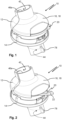
- FIGs 1 and 2 show a fitting 10.
- the fitting 10 is shown in a closed state.
- the fitting 10 is in an open state.
- the fitting 10 comprises a first fitting part 12 and a second fitting part 14.
- the two fitting parts 12, 14 can be connected to each other via screws (not shown in detail here).
- the fitting parts 12, 14 can have edge sections for contact with a tabletop from the top or bottom.
- a first clamping part 16 in the form of a cover 18 is slidably guided on the first fitting part 12.
- the first clamping part 16 In the closed state of the fitting 10 (see Figure 1 ) the first clamping part 16 is in a clamping position; in the open state of the fitting 10 (compare Figure 2 ) the first clamping part 16 is in a release position.
- the fitting 10 further comprises an actuating element 20.
- the actuating element 20 may have a projection 22 for deflecting the actuating element 20 with the fingers of a hand. By actuating the actuating element 20, the first clamping part 16 can be moved into the clamping position or release position.
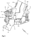
- Figure 9 the fitting 10 is in the closed position (compare Figure 1 ) is shown in a sectional view.
- Figure 10 shows a further view of the first clamping part 16 formed by the cover 18.
- Figure 11 shows a table 30.
- the table 30 has a table top 32.
- the table 30 further has a table frame 34.
- the table frame 34 is here provided with two Columns 36 are formed.
- the two columns 36 can be straight overall.
- the columns 36 extend parallel to one another. In this case, the columns 36 are aligned at an angle.
- a support leg 38 is pivotally connected to each of the columns 36. In the unfolded state, the support legs 38 hold the columns 36 at the predefined inclination relative to the vertical.
- the two support legs 38 can be connected to one another via a cross brace 40 .
- the table top 32 is height-adjustable on the columns 36.
- two fittings 10, 10' are inserted into openings in the table top 32.
- the columns 36 extend through the fittings 10, 10'.
- the two fittings 10, 10' of the table 30 are mirror-symmetrical to each other.
- Figures 3 to 8 The individual parts shown can be assembled in two different configurations to obtain the mirror-symmetrical fittings 10, 10'.
- the assembly state of the fitting 10 corresponds to that of the Figures 1, 2 and 9 fitting 10 shown.
- the table top 32 is clamped to the columns 36.
- the first and second clamping parts 16, 26 of the fittings 10, 10' are each moved into the clamped position by means of the actuating elements 20.
- the first and second clamping parts 16, 26 are each moved into the release position by means of the actuating elements 20.
- the table top 32 can then be tilted and moved along the columns 36.
- the fittings 10, 10' are closed again by means of the actuating elements 20.
- the first fitting part 12 has a first contact section 42 for contact with the column 36.
- the second fitting part 14 has a second contact section 44 for contact with the column 36.
- the contact sections 42, 44 of the two fitting parts 12, 14 are designed to contact the column 36 from opposite directions, see in particular Figure 9 When the table 30 is in use, the contact sections 42, 44 rest against the column 36 from the rear and front, respectively. To adjust the height of the table top 32, the contact sections 42, 44 are removed from the column 36.
- the contact sections 42, 44 can each have a friction lining 46a, 46b .
- the friction lining 46a, 46b can each be a rubber element.
- the friction linings 46a, 46b increase the friction between the contact sections 42, 44 and the column 36.
- the first and second fitting parts 12, 14 each have a bearing seat 48, 50 for the rotatable mounting of the bolt 24, see Figures 5 and 8 .
- a further bearing seat 48', 50' is provided for the mirror-inverted assembly of the bolt 24.
- the bearing seats 48, 48' are formed by interconnected recesses.
- the bearing seats 50, 50' are formed by separate recesses.
- radial wall sections 52 can be provided on the bolt 24, see Figure 6 .
- the actuating element 20 is rotationally coupled to the bolt 24. In other words, actuation of the actuating element 20 causes rotation of the bolt 24 about its bolt axis 25.
- the actuating element 20 (compare Figure 4 ) has a non-rotationally symmetrical recess 54, which can be formed with two partial recesses, for engagement or penetration of the bolt 24.
- the bolt 24 has a terminal bolt section 56 and an extension 58 offset from the bolt axis 25, see Figure 6
- the extension 58 can project in the axial direction beyond the terminal bolt section 56.
- the terminal bolt section 56 engages in the mounted state in the recess 54 of the actuating element 20; the extension 58 projects through the recess 54 (see also Figure 9 ).
- the cover 18 can have a further friction lining 46c , which in the closed state of the fitting 10, ie when the first clamping part 16 formed by the cover 18 is in the clamping position, rests against the column 36, compare Figure 9 .
- the first clamping part 16 has an elongated recess 62 which runs transversely to the direction of displacement, compare Figures 9 and 10
- the eccentric extension 58 of the bolt 24 engages the elongated recess 62. Rotation of the bolt 24 thus causes the first clamping part 16 to move between the clamping position and the release position.
- a locking mechanism is provided between the actuating element 20 and the cover 18.
- the cover 18 has a locking contour 64 (see Figure 10 ), which is connected to a nose 66 of the actuating element 20 (compare Figure 4 ).
- the nose 66 of the actuating element 20 presses the first clamping part 16 against the column 36.
- the clamping ring 28 forming the second clamping part 16 is slidably guided on the second fitting part 14.
- Corresponding guide devices 68a, 68b are formed on the second fitting part 14 below the clamping ring 28, see Figures 7 and 8 .
- the clamping ring 28 may have a friction lining 46d for engagement with the column 36.
- the clamping ring 28 has two elongated holes 70, 70' through which a second bolt section 72 can be guided for engagement in the bearing seats 50 and 50' in the second fitting part 14.
- the second clamping part 26 In order to move the second clamping part 26 (the clamping ring 28) between the release position and the clamping position upon rotation of the bolt 24, the second clamping part 26 and the bolt 24 interact via a toothing.
- a first toothing section 74 in the form of a gear segment is formed on the bolt 24.
- Two second toothing sections 76, 76' in the form of toothed racks are formed on the second clamping part 26 (symmetrical to a center plane).
- the first toothing section 74 of the bolt 24 interacts with the second toothing section 76 or 76' of the second clamping part 26.
- the bolt 24 is inserted in a correspondingly rotated position.
- the engagement positions for the bolt 24 in the fitting parts 12, 14 (engagement in the bearing seats 48 and 50 or 48' and 50') as well as the penetration through the clamping ring 28 (penetration through the elongated hole 70 or 70') change accordingly.
- the actuating element 20 is also placed on the bolt 24 in a correspondingly rotated position. Otherwise, there are no differences for the assembly of fitting 10 or 10'.
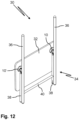
- Figure 12 shows the table 30 in a folded state.
- the support legs 38 are folded onto the columns 36.
- the table top 32 is removed from the columns 36.
- the table top 32 can be hung on the support legs 38 using hook elements 78.
- the hook elements 78 are formed on the second fitting parts 14, here molded onto them.
- the invention relates to a fitting for adjusting the height of a table top on a column and to a table with such a fitting.
- a table top is held frictionally to the column by means of the fitting.
- the frictional engagement is released by tilting the table top relative to the column.
- At least one clamping part is provided in the fitting. Using an actuating element, the clamping part can be brought into contact with the column, preventing the tabletop from tilting relative to the column.
- the clamping part can be removed from the column using the actuating element, allowing the tabletop to tilt relative to the column.
Landscapes
- Furniture Connections (AREA)
Description
- Die Erfindung betrifft einen Beschlag zum Festklemmen einer Tischplatte an einer den Beschlag durchragenden Säule, aufweisend
- ein erstes und ein zweites Beschlagteil mit je einem Anlageabschnitt zur Anlage an der Säule aus entgegengesetzten Richtungen,
- wenigstens ein in eine Freigabestellung und eine Klemmstellung verbringbares Klemmteil und
- ein Betätigungselement, das relativ zu den Beschlagteilen beweglich ist, um das Klemmteil zwischen der Freigabestellung und der Klemmstellung zu verbringen.
- Die Erfindung betrifft ferner einen höhenverstellbaren Tisch aufweisend ein Tischgestell mit einer Säule und eine Tischplatte.
- Ein solcher Beschlag ist aus
DE 199 14 184 A1 bekannt. -
DE 199 14 184 A1 beschreibt eine an einer vertikalen Tragstange festlegbare Klammer. Die Tragstange ist zwischen dem Boden und der Decke fixierbar. Die Klammer wird von einem Paar von getrennten Teilen gebildet, die je eine halbkreisförmige Druckfläche aufweisen. Bei dem Paar von Teilen tritt ein Verbindungsbolzen durch das erste Teil hindurch, so dass der Kopf an diesem anliegt. An dem zweiten Teil, welches an der anderen Seite der Stange angeordnet ist, ist für den Verbindungsbolzen eine Mutter angelegt. An der Klammer kann eine Konsole für ein Regalbrett befestigt werden. -
FR 2 829 808 A1 - Ein aus
DE 20 2013 008 627 U1 bekannter Beistelltisch besteht aus einer Fußplatte, einer daran montierten Stange und einer an der Stange bewegbaren Tischplatte. An der Tischplatte ist ein Flansch angebracht. In dem Flansch sind zwei Bremsbacken montiert. Die Bremsbacken sind so angeordnet, dass die Platte höhenverstellt werden kann, sobald sie entgegen der Schwerkraft angekippt wird. Die Tischplatte ist außerhalb der Mitte an der Stange aufgehängt, sodass das Eigengewicht der Tischplatte für den für eine Fixierung durch Verklemmen nötigen Anpressdruck sorgt. In dem Flansch kann eine Druckfeder montiert sein, um die Tischplatte nach dem Verstellen in die Klemmung zurück zu drücken. - Bei dieser Art der Verklemmung der Tischplatte an der Stange besteht jedoch die Gefahr, dass beim Anstoßen der Tischplatte von unten die Klemmwirkung aufgehoben wird, sodass die Tischplatte absacken kann.
- Es sind ferner höhenverstellbare Schreibtische mit manuell oder kraftunterstützt teleskopierbaren Beinen zahlreich bekannt. Diese sind jedoch im Allgemeinen relativ schwer, konstruktiv aufwendig und entsprechend teuer.
- Es ist eine Aufgabe der Erfindung, eine einfache und schnelle Höhenverstellung einer sicher fixierbaren Tischplatte zu ermöglichen.
- Diese Aufgabe wird erfindungsgemäß gelöst durch einen Beschlag mit den in Anspruch 1 angegebenen Merkmalen und einen Tisch gemäß Anspruch 13.
- Der erfindungsgemäße Beschlag dient zum Festklemmen einer Tischplatte in unterschiedlichen Höhen an einer den Beschlag durchragenden Säule. Die Säule ist dabei vorzugsweise schräg, d. h. gegenüber der Vertikalen geneigt, ausgerichtet. Der Beschlag bewirkt dabei eine horizontale Ausrichtung der Tischplatte im festgeklemmten Zustand. Der Beschlag ermöglicht es, die Tischplatte in unterschiedlichen Höhen (Positionen) an der Säule festzulegen und für ein Verstellen der Höhe der Tischplatte die Verklemmung aufzuheben.
- Der Beschlag weist ein erstes und ein zweites Beschlagteil auf. Die Beschlagteile weisen jeweils einen Anlageabschnitt zur Anlage an der Säule auf. Die Anlageabschnitte der beiden Beschlagteile sind für eine Anlage an der Säule aus unterschiedlichen Richtungen an den Beschlagteilen angeordnet. Beispielsweise kann einer der Anlageabschnitte dazu eingerichtet sein, von hinten (von einem Benutzer eines Tisches mit dem Beschlag aus gesehen) und der andere der Anlageabschnitte von vorne an der Säule anzuliegen. Die beiden Anlageabschnitte können jeweils einen Reibbelag aufweisen. Der Reibbelag erhöht die Reibung zwischen den Beschlagteilen und der Säule.
- Die beiden Beschlagteile können starr mit der Tischplatte verbunden werden. Sie können insbesondere aus unterschiedlichen Richtungen (zum Beispiel von oben und von unten) in eine Öffnung der Tischplatte einsetzbar sein. Vorzugsweise sind die beiden Beschlagteile unmittelbar miteinander verbindbar, insbesondere lösbar miteinander verbindbar. Die beiden Beschlagteile können miteinander verschraubbar sein.
- Für einen Gebrauch eines Tisches mit dem Beschlag liegen die beiden Anlageabschnitte, insbesondere die Reibbeläge, an der Säule an. Die Tischplatte wird dadurch reibschlüssig an der Säule gehalten. Zum Verstellen der Höhe der Tischplatte werden die Anlageabschnitte durch Kippen der Tischplatte von der Säule entfernt. Die Tischplatte mit den Beschlägen kann dann stufenlos an der Säule verschoben werden.
- Der Beschlag weist weiterhin wenigstens ein Klemmteil auf. Das wenigstens eine Klemmteil ist in eine Freigabestellung und eine Klemmstellung verbringbar. Zwischen der Freigabestellung und der Klemmstellung kann sich das wenigstens eine Klemmteil typischerweise um einige Millimeter, beispielsweise zwischen 4 mm und 8 mm, bewegen. In der Freigabestellung des wenigstens einen Klemmteils ermöglicht der Beschlag ein Durchführen der Säule unter Beabstandung der Anlageabschnitte von der Säule. Somit kann die Höhe einer Tischplatte eines Tisches mit dem Beschlag verstellt werden, wenn sich das wenigstens eine Klemmteil in der Freigabestellung befindet. In der Klemmstellung erzwingt das wenigstens eine Klemmteil eine Anlage der Anlageabschnitte an der Säule. Ein Verstellen der Höhe der Tischplatte ist mithin nicht möglich, wenn sich das wenigstens eine Klemmteil in der Klemmstellung befindet. Wenn sich das Klemmteil in der Klemmstellung befindet, ist insbesondere sichergestellt, dass die Höhe der Tischplatte nicht versehentlich verstellt wird, beispielsweise wenn die Tischplatte von unten angestoßen wird.
- Ein Tisch mit dem erfindungsgemäßen Beschlag ist daher besonders sicher zu benutzen.
- In der Klemmstellung kann das wenigstens eine Klemmteil selbst an der Säule anliegen, um die Anlage der Anlageabschnitte an der Säule zu erzwingen. Für eine besonders sichere Fixierung kann das wenigstens eine Klemmteil einen Reibbelag aufweisen.
- Vorzugsweise weist der Beschlag ein erstes Klemmteil für das erste Beschlagteil und ein zweites Klemmteil für das zweite Beschlagteil auf. In der Klemmstellung kann dabei jedes der beiden Klemmteile sicherstellen, dass der Anlageabschnitt des jeweils zugeordneten Beschlagteils nicht von der Säule abgehoben werden kann. Durch die Verwendung von zwei Klemmteilen kann der Beschlag besonders sicher und zuverlässig an der Säule fixiert werden.
- Der Beschlag weist ferner ein Betätigungselement auf, um das wenigstens eine Klemmteil zwischen der Freigabestellung und der Klemmstellung zu verbringen. Das Betätigungselement ist hierzu relativ zu den Beschlagteilen beweglich. Das Betätigungselement und das Klemmteil können starr miteinander verbunden sein. Insbesondere können das Betätigungselement und das Klemmteil Abschnitte eines gemeinsamen Bauteils sein. Vorzugsweise sind das Betätigungselement und das wenigstens eine Klemmteil voneinander separate Bauteile. Typischerweise sind das Betätigungselement und das wenigstens eine Klemmteil relativ zueinander beweglich, insbesondere rotatorisch und/oder translatorisch. Das Betätigungselement und das Klemmteil sind grundsätzlich miteinander bewegungsgekoppelt. Mit andern Worten bewirkt eine Bewegung des Betätigungselements eine Bewegung des Klemmteils.
- Das Betätigungselement ermöglicht es auf einfache Weise, einerseits den Beschlag für einen Gebrauch eines Tisches mit dem Beschlag zu sperren, d. h. das Klemmteil in der Klemmstellung zu halten, und andererseits ein Verstellen der Höhe zu ermöglichen, d. h. das Klemmteil in die Freigabestellung zu verbringen. Das Betätigungselement vereinfacht mithin die sichere Benutzung des Tisches mit dem Beschlag.
- Der Beschlag kann kostengünstig hergestellt werden. Die Komponenten des Beschlags können Spritzgussteile, insbesondere Kunststoffspritzgussteile, sein. Durch den Beschlag kann ein leichter und preisgünstiger höhenverstellbarer Tisch bereitgestellt werden.
- Das Betätigungselement kann beispielsweise ein Hebel oder ein Schieber sein. Das Betätigungselement kann für eine Betätigung mit einem Finger, insbesondere einem Daumen, ausgebildet sein. Typischerweise ist das Betätigungselement an dem ersten oder dem zweiten Beschlagteil angeordnet.
- Vorzugsweise ist an dem ersten Beschlagteil eine Blende verschieblich geführt. Die Blende kann ein erstes Klemmteil bilden. Durch Verschieben der Blende zu dem Anlageabschnitt des ersten Beschlagteils hin bzw. von dem Anlageabschnitt des ersten Beschlagteils weg kann der Beschlag zum Fixieren einer Position an der Säule geschlossen, d. h. das erste Klemmteil in die Klemmstellung verbracht, bzw. zum Verstellen der Position geöffnet, d. h. das erste Klemmteil in die Freigabestellung verbracht, werden. Indem das erste Klemmteil durch die Blende gebildet ist, können Spalte im Bereich des ersten Beschlagteils für den Gebrauch eines Tisches mit dem Beschlag minimiert werden.
- Erfindungsgemäß ist vorgesehen, dass eine Verrastung das Klemmteil in der Klemmstellung hält. Dadurch kann vermieden werden, dass das Klemmteil unbeabsichtigt in die Freigabestellung übergeht.
- Besonders bevorzugt wirkt die Verrastung zwischen dem Betätigungselement und der Blende. Beim Verrasten des Betätigungselements an der Blende kann die Blende zusätzlich gegen die Säule gepresst werden. Dies bewirkt eine besonders feste Fixierung des Beschlags an der Säule.
- Bevorzugt weist der Beschlag einen Klemmring auf. Der Klemmring kann ein zweites Klemmteil bilden. Der Klemmring kann eine allseitig geschlossene Öffnung zum Durchführen der Säule aufweisen. Die Öffnung ist typischerweise in der Art eines Langlochs ausgebildet. Der Klemmring kann die Säule umgreifen. Eine Komponente einer translatorischen Bewegung des Klemmrings beim Verbringen zwischen der Freigabestellung und der Klemmstellung kann quer zur Säule verlaufen.
- Besonders bevorzugt ist der Klemmring an dem zweiten Beschlagteil verschieblich geführt. Durch Verschieben des Klemmrings zu dem Anlageabschnitt des zweiten Beschlagteils hin bzw. von dem Anlageabschnitt des zweiten Beschlagteils weg kann der Beschlag zum Fixieren einer Position an der Säule geschlossen, d. h. das zweite Klemmteil in die Klemmstellung verbracht, bzw. zum Verstellen der Position geöffnet, d. h. das zweite Klemmteil in die Freigabestellung verbracht, werden. Die Führung des Klemmrings an dem zweiten Beschlagteil ermöglicht einen besonders kompakten Aufbau des Beschlags. Vorteilhafterweise ist der Klemmring in einem von dem ersten und dem zweiten Beschlagteil eingeschlossenen Innenraum angeordnet.
- An dem Beschlag kann ein Bolzen um eine Bolzenachse drehbar gelagert sein. Vorzugsweise wirkt das Betätigungselement mit dem Bolzen zusammen. Mit anderen Worten kann der Bolzen durch Betätigen des Betätigungselements um die Bolzenachse gedreht werden. Das Betätigungselement kann über den Bolzen am Beschlag gelagert sein. Das Betätigungselement und der Bolzen sind vorzugsweise unverdrehbar bezüglich der Bolzenachse an einander gehalten. Vorzugsweise bewirkt eine Drehung des Bolzens eine Bewegung des wenigstens einen Klemmteils zwischen der Klemmstellung und der Freigabestellung. Der Bolzen ermöglicht es, eine Kopplung des Betätigungselements mit dem Klemmteil, insbesondere mit zwei voneinander separaten Klemmteilen, einzurichten.
- Vorzugsweise ist in dem ersten und dem zweiten Beschlagteil jeweils ein Lagersitz für den Bolzen ausgebildet. Dies ermöglicht eine in axialer Richtung bezüglich der Bolzenachse beanstandete Lagerung des Bolzens. Die breite Abstützung des Bolzens erhöht die Steifigkeit. Dies ist für das Halten des wenigstens einen Klemmteils in der Klemmstellung vorteilhaft. Sofern ein Klemmring als ein Klemmteil vorgesehen ist, kann der Klemmring ein Langloch aufweisen, durch welches der Bolzen ragt.
- Der Bolzen kann einen endständigen Bolzenabschnitt und einen von der Bolzenachse beabstandet Fortsatz aufweisen. Der eigenständige Bolzenabschnitt ist typischerweise konzentrisch zur Bolzenachse. Vorzugsweise greifen der endständige Bolzenabschnitt und der Fortsatz in eine Ausnehmung des Betätigungselements ein. Dadurch kann eine formschlüssige Kopplung des Bolzens und des Betätigungselements erreicht werden, sodass der Bolzen mittels des Betätigungselement gedreht werden kann. Es können separate Ausnehmungen oder eine gemeinsame Ausnehmung für den Bolzenabschnitt und den Fortsatz im Betätigungselement vorgesehen sein. Der Fortsatz kann das Betätigungselement durchragen. Mit anderen Worten kann ein freies Ende des Fortsatzes über das Betätigungselement überstehen.
- Besonders bevorzugt greift der Fortsatz in eine langgestreckte Rücknehmung des Klemmteils, insbesondere des ersten Klemmteils, ein. Die Rücknehmung erstreckt sich zumindest abschnittsweise quer zu einer Bewegungsrichtung des (ersten) Klemmteils. Insbesondere kann sich die Rücknehmung zumindest bereichsweise quer zu einer Verschiebesichtung einer am ersten Beschlagteil geführten Blende, welche das erste Klemmteil bildet, verlaufen. Bei einer Drehung des Bolzens bewirkt der Eingriff des exzentrisch zur Bolzenachse angeordneten Fortsatzes eine Verschiebung des (ersten) Klemmteils. Der Eingriff des Fortsatzes in die Rücknehmung ermöglicht die Ausbildung einer einfachen montierbaren Kopplung zwischen dem Bolzen und dem (ersten) Klemmteil.
- Der Bolzen und das Klemmteil, insbesondere das zweite Klemmteil, können über jeweilige Verzahnungsabschnitte zusammenwirken. An den Bolzen kann ein Zahnrad oder ein Zahnradsegment angeformt sein. Das Zahnradsegment kann einem exzentrischen Fortsatz des Bolzens bezüglich der Bolzenachse gegenüberliegend angeordnet sein. Dadurch kann beim Drehen des Bolzens eine gegenläufige Bewegung der beiden Klemmteile erreicht werden. Das (zweite) Klemmteil kann wenigstens eine Zahnstange aufweisen. Vorzugsweise ist die Zahnstange an das (zweite) Klemmteil angeformt. Über den Eingriff der Verzahnungsabschnitte kann das (zweite) Klemmteil durch eine Drehung des Bolzens mit großer Kraft gegen die Säule gedrückt werden.
- Besonders bevorzugt ist der Beschlag in zwei zueinander spiegelsymmetrischen Konfigurationen zusammenbaubar. Dieselben Komponenten ermöglichen es somit, einen Beschlag zur Verwendung an einer rechten oder an einer linken Säule eines Tisches mit zwei Säulen und zwei Beschlägen zu erhalten. Die vorgenannten Komponenten des Beschlags sind hierzu je selbst spiegelsymmetrisch. Symmetrieebenen des ersten und zweiten Beschlagteils sowie ggf. der Blende und des Klemmrings enthalten eine Säulenachse einer den Beschlag durchragenden Säule. Eine Symmetrieebene des Bolzens enthält die Bolzenachse. Das Betätigungselement kann sich im Wesentlichen in seiner Symmetrieebene erstrecken. Rastnocken einer Verrastung, Lagersitze für den Bolzen in den Beschlagteilen, ein Langloch im Klemmring zum Durchführen des Bolzens sowie Verzahnungsabschnitte an dem Klemmring können je doppelt vorhanden sein.
- In den Rahmen der vorliegenden Erfindung fällt ferner ein höhenverstellbarer Tisch. Der Tisch weist ein Tischgestell mit einer Säule auf. Die Säule erstreckt sich zumindest abschnittsweise geradlinig. Die Säule ist vorzugsweise schräg ausgerichtet. Mit anderen Worten kann die Säule gegenüber der Vertikalen geneigt verlaufen. Der Tisch weist weiterhin eine Tischplatte auf. An der Tischplatte ist ein oben beschriebener, erfindungsgemäßer Beschlag angeordnet. Der Beschlag ermöglicht es, die Tischplatte in unterschiedlichen Höhen (Positionen) an der Säule festzuklemmen und für ein Verstellen der Höhe der Tischplatte die Verklemmung aufzuheben.
- Der Beschlag ist im Allgemeinen an einer Öffnung in der Tischplatte angeordnet. Insbesondere können die beiden Beschlagteile von unterschiedlichen Seiten in die Öffnung eingesetzt sein.
- Der Beschlag ist grundsätzlich exzentrisch an der Tischplatte (abseits ihres Schwerpunkts) angeordnet. Durch das Eigengewicht der Tischplatte werden die Anlageabschnitte des Beschlags gegen die Säule gepresst, wenn die Tischplatte nicht aktiv gegen die Wirkung der Schwerkraft angekippt wird. Durch das Eigengewicht der Tischplatte werden die Anlageabschnitte vorzugsweise so stark gegen die Säule gepresst, dass die Tischplatte in der eingestellten Höhe verbleibt. Mit anderen Worten genügt in der Regel die Anpressung der Anlageabschnitte gegen die Säule zum Fixieren der Tischplatte an der Säule, auch wenn sich das wenigstens eine Klemmteil in der Freigabestellung befindet. Die geneigte Ausrichtung der Säule verstärkt (bei gleicher Exzentrizität des Beschlags zum Schwerpunkt der Tischplatte) die Klemmwirkung. Der Beschlag ist typischerweise derart auf die Neigung der Säule abgestimmt, dass die an der Säule fixierte Tischplatte horizontal ausgerichtet ist.
- Wenn sich das wenigstens eine Klemmteil in der Freigabestellung befindet, kann die Tischplatte gegen die Schwerkraftwirkung angekippt und zur Einstellung der Höhe entlang der Säule verfahren werden. Die derart eingestellte Höhe wird nach dem Loslassen der Tischplatte durch den Reibschluss zwischen den Anlageabschnitten des Beschlags und der Säule gehalten.
- Um ein (unbeabsichtigtes) Verändern der Höhe der Tischplatte zu vermeiden, wird das wenigstens eine Klemmteil mittels des Betätigungselements in die Klemmstellung verbracht. Das wenigstens eine Klemmteil liegt hierbei vorzugsweise unmittelbar an der Säule an. In der Klemmstellung erzwingt das wenigstens eine Klemmteil eine Anlage der Anlageabschnitte der beiden Beschlagteile an der Säule. Insbesondere kann das Klemmteil in der Klemmstellung ein Verkippen der Tischplatte verhindern.
- Die Säule kann ein Rohr, insbesondere ein Metallrohr sein. Die Tischplatte kann aus Holz bestehen oder mit einem Holzwerkstoff gefertigt sein.
- Der erfindungsgemäße Tisch kann kostengünstig bereitgestellt werden. Ferner kann der erfindungsgemäße Tisch für einen höhenverstellbaren Tisch relativ leicht sein. Durch den erfindungsgemäßen Beschlag ist einerseits die Höhe der Tischplatte in einfacher Weise und schnell verstellbar, andererseits kann die Tischplatte in der eingestellten Höhe zuverlässig fixiert werden. Zum Verändern der Höhe wird das Klemmteil mittels des Betätigungselements in die Freigabestellung verbracht, sodann wird die Tischplatte gegen die Schwerkraftwirkung angekippt (angehoben) und in die gewünschte Höhe verschoben, schließlich wird das Klemmteil mittels des Betätigungselements wieder in die Klemmstellung überführt. Dies kann mit wenigen, einfachen Handgriffen und insbesondere ohne Werkzeug oder sonstige Hilfsmittel erfolgen.
- Der Tisch kann beispielsweise als Schreibtisch, als Beistelltisch, als Werkbank für Bastelarbeiten oder dergleichen oder als Esstisch verwendet werden. Insbesondere mit mehreren Tischplatten kann der Tisch auch als Regal verwendet werden.
- Das Tischgestell kann eine weitere Säule aufweisen und an der Tischplatte kann ein weiterer Beschlag für die weitere Säule angeordnet sein. Durch die zwei Säulen kann die Standsicherheit des Tisches verbessert werden. Zudem kann durch die beiden Säulen verhindert werden, dass die Tischplatte sich um die Säule drehen kann, auch wenn die Säule einen kreisförmigen Querschnitt aufweist. Eine (gedachte) Verbindungsgerade der Beschläge verläuft grundsätzlich nicht durch den Schwerpunkt der Tischplatte. Die beiden Säulen verlaufen in der Regel zumindest abschnittsweise parallel zueinander.
- Das Tischgestell kann einen Stützschenkel aufweisen. Der Stützschenkel kann die Standsicherheit des Tisches weiter verbessern. Bei einem Tischgestell mit zwei Säulen sind typischerweise zwei Stützschenkel vorgesehen Vorzugsweise ist der Stützschenkel klappbar an der (jeweiligen) Säule angelenkt. Dies ermöglicht es, das Tischgestell für Phasen des Nichtgebrauchs platzsparend zusammen zu klappen.
- Vorzugsweise kann die Tischplatte von der Säule abgezogen werden, wenn sich das Klemmteil in der Freigabestellung befindet. Dadurch kann der Tisch zur Aufbewahrung oder für einen Transport in einfacher Weise zerlegt werden.
- Weitere Merkmale und Vorteile der Erfindung ergeben sich aus den Ansprüchen, der Beschreibung und der Zeichnung. Erfindungsgemäß können die vorstehend genannten und die noch weiter ausgeführten Merkmale jeweils einzeln für sich oder zu mehreren in beliebigen, zweckmäßigen Kombinationen Verwendung finden. Die gezeigten und beschriebenen Ausführungsformen sind nicht als abschließende Aufzählung zu verstehen, sondern haben vielmehr beispielhaften Charakter für die Schilderung der Erfindung.
- Die Erfindung ist in der Zeichnung dargestellt und wird anhand von Ausführungsbeispielen beschrieben. Es zeigen:
- Fig. 1
- einen erfindungsgemäßen Beschlag mit einem ersten und einem zweiten Beschlagteil, wobei sich eine ein erstes Klemmteil bildende Blende in einer Klemmstellung befindet, in einer schematischen Perspektivansicht;
- Fig. 2
- den Beschlag von
Figur 1 , wobei die Blende durch Betätigen eines Betätigungselements in eine Freigabestellung überführt wurde, in einer schematischen Perspektivansicht; - Fig. 3
- die Blende des Beschlags von
Figur 1 in einer freigestellten, schematischen Perspektivansicht; - Fig. 4
- das Betätigungselement des Beschlags von
Figur 1 in einer freigestellten, schematischen Perspektivansicht; - Fig. 5
- das erste Beschlagteil des Beschlags von
Figur 1 in einer freigestellten, schematischen Perspektivansicht; - Fig. 6
- einen über das Betätigungselement drehbaren Bolzen des Beschlags von
Figur 1 in einer freigestellten, schematischen Perspektivansicht; - Fig. 7
- einen durch eine Drehung des Bolzens verschiebbaren Klemmring, welcher ein zweites Klemmteil des Beschlags von
Figur 1 bildet, in einer freigestellten, schematischen Perspektivansicht; - Fig. 8
- das zweite Beschlagteil des Beschlags von
Figur 1 in einer freigestellten, schematischen Perspektivansicht; - Fig. 9
- eine schematische Schnittansicht durch den Beschlag von
Figur 1 ; - Fig. 10
- eine weitere schematische Perspektivansicht der Blende des Beschlags von
Figur 1 ; - Fig. 11
- einen erfindungsgemäßen Tisch mit zwei Säulen, an welchen eine Tischplatte durch zwei erfindungsgemäße Beschläge höhenverstellbar gehalten ist, in einer schematischen Perspektivansicht;
- Fig. 12
- den Tisch von
Figur 11 in einem zusammengefalteten Zustand, in einer schematischen Perspektivansicht. - Die
Figuren 1 und 2 zeigen einen Beschlag 10. InFigur 1 ist der Beschlag 10 in einem geschlossenen Zustand dargestellt. InFigur 2 befindet sich der Beschlag 10 in einem geöffneten Zustand. - Der Beschlag 10 weist ein erstes Beschlagteil 12 und ein zweites Beschlagteil 14 auf. Die beiden Beschlagteile 12, 14 können über hier nicht näher dargestellte Schrauben miteinander verbunden sein. Die Beschlagteile 12, 14 können Randabschnitte zur ober- bzw. unterseitigen Anlage an einer Tischplatte aufweisen.
- An dem ersten Beschlagteil 12 ist ein erstes Klemmteil 16 in Form einer Blende 18 verschieblich geführt. Im geschlossenen Zustand des Beschlags 10 (vergleiche
Figur 1 ) befindet sich das erste Klemmteil 16 in einer Klemmstellung; im geöffneten Zustand des Beschlags 10 (vergleicheFigur 2 ) befindet sich das erste Klemmteil 16 in einer Freigabestellung. - Der Beschlag 10 weist ferner ein Betätigungselement 20 auf. Das Betätigungselement 20 kann einen Vorsprung 22 zum Auslenken des Betätigungselement 20 mit Fingern einer Hand aufweisen. Durch Betätigen des Betätigungselements 20 kann das erste Klemmteil 16 in die Klemmstellung bzw. Freigabestellung verbracht werden.
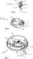
- Einzelteile des Beschlags 10 sind nachfolgend in einzelnen Figuren dargestellt. Hierbei zeigen
-
Figur 3 : die das erste Klemmteil 16 bildende Blende 18, -
Figur 4 : das Betätigungselement 20, -
Figur 5 : das erste Beschlagteil 14, -
Figur 6 : einen Bolzen 24, -
Figur 7 : ein zweites Klemmteil 26 in Form eines Klemmrings 28, -
Figur 8 : das zweite Beschlagteil 14. - In
Figur 9 ist der Beschlag 10 im geschlossenen Zustand (vergleicheFigur 1 ) in einer Schnittansicht gezeigt.Figur 10 zeigt eine weitere Ansicht des durch die Blende 18 gebildeten ersten Klemmteils 16. -
Figur 11 zeigt einen Tisch 30. Der Tisch 30 weist eine Tischplatte 32 auf. Der Tisch 30 weist ferner ein Tischgestell 34 auf. Das Tischgestell 34 ist hier mit zwei Säulen 36 gebildet. Die beiden Säulen 36 können insgesamt geradlinig verlaufen. Die Säulen 36 erstrecken sich parallel zueinander. Die Säulen 36 sind vorliegend schräg ausgerichtet. Bei der dargestellten Ausführungsform des Tisches 30 ist an jeder der Säulen 36 ein Stützschenkel 38 schwenkbar angelenkt. Im ausgeklappten Zustand halten die Stützschenkel 38 die Säulen 36 in der vordefinierten Neigung gegenüber der Vertikalen. Die beiden Stützschenkel 38 können über eine Querstrebe 40 miteinander verbunden sein. - Die Tischplatte 32 ist an den Säulen 36 höhenverstellbar. Hierzu sind zwei Beschläge 10, 10' in Öffnungen der Tischplatte 32 eingesetzt. Die Säulen 36 durchragen die Beschläge 10, 10'. Die beiden Beschläge 10, 10' des Tisches 30 sind zueinander spiegelsymmetrisch. Die in den
Figuren 3 bis 8 gezeigten Einzelteile können in zwei unterschiedlichen Konfigurationen zusammengesetzt werden, um die spiegelsymmetrischen Beschläge 10, 10' zu erhalten. Der Montagezustand des Beschlags 10 entspricht dem des in denFiguren 1, 2 und9 gezeigten Beschlag 10. - Für einen Gebrauch des Tisches 30 wird die Tischplatte 32 an den Säulen 36 festgeklemmt. Die ersten und zweiten Klemmteile 16, 26 der Beschläge 10, 10' werden hierzu jeweils mittels der Betätigungselemente 20 in die Klemmstellung verbracht. Zur Höhenverstellung der Tischplatte 32 werden die ersten und zweiten Klemmteile 16, 26 jeweils mittels der Betätigungselemente 20 in die Freigabestellung verbracht. Die Tischplatte 32 kann dann angekippt und entlang der Säulen 36 verschoben werden. Beim Loslassen der Tischplatte 32 wird diese über die Beschläge 10, 10' wieder an den Säulen 36 festgeklemmt. Um die eingestellte Höhe zu sichern, insbesondere gegen ein unbeabsichtigtes Verstellen bei Kontakt mit der Tischplatte 32, werden die Beschläge 10, 10' mittels der Betätigungselemente 20 wieder geschlossen.
- Das Zusammenwirken der Einzelteile des Beschlags 10 bzw. 10' miteinander und mit der jeweils zugeordneten Säule 36 wird nachfolgend im Einzelnen beschrieben.
- Das erste Beschlagteil 12 weist einen ersten Anlageabschnitt 42 zur Anlage an der Säule 36 auf. Das zweite Beschlagteil 14 weist einen zweiten Anlageabschnitte 44 zur Anlage an der Säule 36 auf. Die Anlageabschnitte 42, 44 der beiden Beschlagteile 12, 14 sind zur Anlage aus entgegengesetzten Richtungen an der Säule 36 ausgebildet, vergleiche insbesondere
Figur 9 . Bei Benutzung des Tisches 30 liegen die Anlageabschnitte 42, 44 von hinten bzw. vorne an der Säule 36 an. Zur Höhenverstellung der Tischplatte 32 werden die Anlageabschnitte 42, 44 von der Säule 36 entfernt. Die Anlageabschnitte 42, 44 können jeweils einen Reibbelag 46a, 46b aufweisen. Der Reibbelag 46a, 46b kann je ein Gummielement sein. Die Reibbeläge 46a, 46b erhöhen die Reibung zwischen den Anlageabschnitten 42, 44 und der Säule 36. - Das erste und das zweite Beschlagteil 12, 14 weisen je einen Lagersitz 48, 50 zur drehbaren Lagerung des Bolzens 24 auf, vergleiche
Figuren 5 und8 . Vorliegend ist jeweils ein weiterer Lagersitz 48', 50' zur spiegelverkehrten Montage des Bolzens 24 vorgesehen. Im ersten Beschlagteil 12 sind die Lagersitze 48, 48' durch miteinander verbundene Ausnehmungen gebildet. Im zweiten Beschlagteil 14 sind die Lagersitze 50, 50' durch voneinander separate Ausnehmungen gebildet. Für den Eingriff in den Lagersitz 48 des ersten Beschlagteils 12 können am Bolzen 24 radiale Wandabschnitte 52 vorgesehen sein, vergleicheFigur 6 . - Das Betätigungselement 20 ist mit dem Bolzen 24 drehgekoppelt. Mit anderen Worten bewirkt eine Betätigung des Betätigungselements 20 eine Drehung des Bolzens 24 um seine Bolzenachse 25. Das Betätigungselement 20 (vergleiche
Figur 4 ) weist eine nichtrotationsymmetrische Ausnehmung 54, die mit zwei Teilausnehmungen gebildet sein kann, für einen Eingriff bzw. Durchgriff des Bolzens 24 auf. Der Bolzen 24 weist einen endständigen Bolzenabschnitt 56 und einen gegenüber der Bolzenachse 25 versetzten Fortsatz 58 auf, vergleicheFigur 6 . Der Fortsatz 58 kann in axialer Richtung über den endständigen Bolzenabschnitt 56 hinaus vorstehen. Der endständige Bolzenabschnitt 56 greift im montierten Zustand in die Ausnehmung 54 des Betätigungselements 20 ein; der Fortsatz 58 durchragt die Ausnehmung 54 (vergleiche auchFigur 9 ). - Zur verschieblichen Führung der Blende 18 am ersten Beschlagteil 12 sind an dem ersten Beschlagteil 12 und der Blende 18 zueinander korrespondierende Führungseinrichtungen 60a, 60b ausgebildet, vergleiche
Figuren 5 und10 . Die Blende 18 kann einen weiteren Reibbelag 46c aufweisen, welcher im geschlossenen Zustand des Beschlags 10, d. h. wenn sich das durch die Blende 18 gebildete erste Klemmteil 16 in der Klemmstellung befindet, an der Säule 36 anliegt, vergleicheFigur 9 . - Das erste Klemmteil 16 weist eine langgestreckte Rücknehmung 62 auf, welche quer zur Verschieberichtung verläuft, vergleiche
Figuren 9 und10 . Der exzentrische Fortsatz 58 des Bolzens 24 greift in die langgestreckte Rücknehmung 62 ein. Eine Drehung des Bolzens 24 bewirkt mithin eine Bewegung des ersten Klemmteils 16 zwischen der Klemmstellung und der Freigabestellung. - Um den geschlossenen Zustand des Beschlags 10 zu sichern, ist eine Verrastung zwischen dem Betätigungselement 20 und der Blende 18 eingerichtet. Die Blende 18 weist eine Rastkontur 64 auf (vergleiche
Figur 10 ), welche mit einer Nase 66 des Betätigungselements 20 (vergleicheFigur 4 ) zusammenwirkt. Im geschlossenen Zustand des Beschlags 10 drückt die Nase 66 des Betätigungselements 20 das erste Klemmteil 16 gegen die Säule 36. - Der das zweite Klemmteil 16 bildende Klemmring 28 ist verschieblich an dem zweiten Beschlagteil 14 geführt. An dem zweiten Beschlagteil 14 unter dem Klemmring 28 sind hierzu zueinander korrespondierende Führungseinrichtungen 68a, 68b ausgebildet, vergleiche
Figuren 7 und 8 . Der Klemmring 28 kann einen Reibbelag 46d zur Anlage an der Säule 36 aufweisen. - Der Klemmring 28 weist zwei Langlöcher 70, 70' auf, durch welche ein zweiter Bolzenabschnitt 72 für den Eingriff in die Lagersitze 50 bzw. 50' im zweiten Beschlagteil 14 geführt werden kann.
- Um das zweite Klemmteil 26 (den Klemmring 28) bei einer Drehung des Bolzens 24 zwischen der Freigabestellung und der Klemmstellung zu verbringen, wirken das zweite Klemmteil 26 und der Bolzen 24 über eine Verzahnung zusammen. An dem Bolzen 24 ist ein erster Verzahnungsabschnitt 74 in Form eines Zahnradsegments ausgebildet. An dem zweiten Klemmteil 26 sind (symmetrisch zu einer Mittelebene) zwei zweite Verzahnungsabschnitte 76, 76' in Form von Zahnstangen ausgebildet. Je nach montierter Konfiguration des Beschlags 10 bzw. 10' wirkt der erste Verzahnungsabschnitt 74 des Bolzens 24 mit dem zweiten Verzahnungsabschnitt 76 oder 76' des zweiten Klemmteils 26 zusammen.
- Für die Montage des Beschlags 10 oder 10' wird der Bolzen 24 entsprechend gedreht eingesetzt. Die Eingriffspositionen für den Bolzens 24 in die Beschlagteile 12, 14 (Eingriff in die Lagersitze 48 und 50 oder 48' und 50') sowie der Durchgriff durch den Klemmring 28 (Durchragen des Langlochs 70 oder 70') ändern sich hierzu korrespondierend. Auch das Betätigungselement 20 wird entsprechend gedreht auf den Bolzen 24 aufgesetzt. Im Übrigen ergeben sich für die Montage des Beschlag 10 bzw. 10' keine Unterschiede.
-
Figur 12 zeigt den Tisch 30 in einem zusammengeklappten Zustand. Die Stützschenkel 38 sind an die Säulen 36 herangeklappt. Die Tischplatte 32 ist von den Säulen 36 abgezogen. Die Tischplatte 32 kann mithilfe von Hakenelementen 78 an den Stützschenkeln 38 eingehängt werden. Die Hakenelemente 78 sind vorliegend an den zweiten Beschlagteilen 14 ausgebildet, hier an diese angeformt. - Zusammenfassend betrifft die Erfindung einen Beschlag zur Höhenverstellung einer Tischplatte an einer Säule und einen Tisch mit einem solchen Beschlag. Für die Benutzung des Tisches wird eine Tischplatte mittels des Beschlags reibschlüssig an der Säule gehalten. Zum Verändern der Höhe der Tischplatte wird der Reibschluss durch Verkippen der Tischplatte gegenüber der Säule aufgehoben. Um die Tischplatte in der eingestellten Höhe zu sichern, ist an dem Beschlag wenigstens ein Klemmteil vorgesehen. Mittels eines Betätigungselements kann das Klemmteil an der Säule zur Anlage gebracht werden, sodass ein Verkippen der Tischplatte gegenüber der Säule nicht möglich ist. Um die Höhenverstellung zu erlauben, kann das Klemmteil mittels des Betätigungselements von der Säule entfernt werden, sodass ein Verkippen der Tischplatte gegenüber der Säule ermöglicht ist.
-
- Beschlag 10, 10'
- erstes Beschlagteil 12
- zweites Beschlagteil 14
- erstes Klemmteil 16
- Blende 18
- Betätigungselement 20
- Vorsprung 22
- Bolzen 24
- Bolzenachse 25
- zweites Klemmteil 26
- Klemmring 28
- Tisch 30
- Tischplatte 32
- Tischgestell 34
- Säule 36
- Stützschenkel 38
- Querstrebe 40
- erster Anlageabschnitt 42
- zweiter Anlageabschnitt 44
- Reibbelag 46a, 46b, 46c, 46d
- Lagersitz 48, 48', 50, 50'
- Wandabschnitte 52
- Ausnehmung 54
- endständiger Bolzenabschnitt 56
- Fortsatz 58
- Führungseinrichtungen 60a, 60b
- Rücknehmung 62
- Rastkontur 64
- Nase 66
- Führungseinrichtungen 68a, 68b
- Langlöcher 70, 70'
- zweiter Bolzenabschnitt 72
- erster Verzahnungsabschnitt 74
- zweite Verzahnungsabschnitte 76, 76'
- Hakenelement 78
Claims (15)
- Beschlag (10, 10'), zum Festklemmen einer Tischplatte (32) in unterschiedlichen Höhen an einer, vorzugsweise schräg ausgerichteten, den Beschlag (10, 10') durchragenden Säule (36), aufweisend- ein erstes und ein zweites Beschlagteil (12, 14) mit je einem Anlageabschnitt (42, 44) zur Anlage an der Säule (36) aus entgegengesetzten Richtungen,- wenigstens ein in eine Freigabestellung und eine Klemmstellung verbringbares Klemmteil (16, 26) und- ein Betätigungselement (20), das relativ zu den Beschlagteilen (12, 14) beweglich ist, um das Klemmteil (16, 26) zwischen der Freigabestellung und der Klemmstellung zu verbringen,dadurch gekennzeichnet,
dass eine Verrastung das wenigstens eine Klemmteil (16, 26) in der Klemmstellung hält. - Beschlag (10, 10') nach Anspruch 1, dadurch gekennzeichnet, dass ein erstes Klemmteil (16) für das erste Beschlagteil (12) und ein zweites Klemmteil (26) für das zweite Beschlagteil (26) vorgesehen sind.
- Beschlag (10, 10') nach einem der vorhergehenden Ansprüche, dadurch gekennzeichnet, dass an dem ersten Beschlagteil (12) eine Blende (18) verschieblich geführt ist, wobei die Blende (18) ein erstes Klemmteil (16) für das erste Beschlagteil (12) bildet.
- Beschlag (10, 10') nach Anspruch 3, dadurch gekennzeichnet, dass die Verrastung zwischen dem Betätigungselement (20) und der Blende (18) wirkt.
- Beschlag (10, 10') nach einem der vorhergehenden Ansprüche, dadurch gekennzeichnet, dass ein Klemmring (28) ein zweites Klemmteil (26) für das zweite Beschlagteil (26) bildet.
- Beschlag (10, 10') nach Anspruch 5, dadurch gekennzeichnet, dass der Klemmring (28) an dem zweiten Beschlagteil (26) verschieblich geführt ist.
- Beschlag (10, 10') nach einem der vorhergehenden Ansprüche, dadurch gekennzeichnet, dass das Betätigungselement (20) mit einem um eine Bolzenachse (25) drehbar am Beschlag (10, 10') gelagerten Bolzen (24) zusammenwirkt.
- Beschlag (10, 10') nach Anspruch 7, dadurch gekennzeichnet, dass das erste und das zweite Beschlagteil (12, 14) je einen Lagersitz (48, 48'; 50, 50') für den Bolzen (24) aufweisen.
- Beschlag (10, 10') nach Anspruch 7 oder 8, dadurch gekennzeichnet, dass der Bolzen (24) einen endständigen Bolzenabschnitt (56) und einen von der Bolzenachse (25) beabstandeten Fortsatz (58) aufweist, und vorzugsweise dass der endständige Bolzenabschnitt (56) und der Fortsatz (58) in eine Ausnehmung (54) des Betätigungselements (20) eingreifen.
- Beschlag (10, 10') nach Anspruch 9, dadurch gekennzeichnet, dass der Fortsatz (58) in eine langgestreckte Rücknehmung (62) des Klemmteils (16) eingreift.
- Beschlag (10, 10') nach einem der Ansprüche 7 bis 10, dadurch gekennzeichnet, dass der Bolzen (24) und das wenigstens eine Klemmteil (26) über jeweilige Verzahnungsabschnitte (74; 76, 76') zusammenwirken.
- Beschlag (10, 10') nach einem der vorhergehenden Ansprüche, dadurch gekennzeichnet, dass der Beschlag (10, 10') in zwei zueinander spiegelsymmetrischen Konfigurationen zusammenbaubar ist.
- Höhenverstellbarer Tisch (30) aufweisend- ein Tischgestell (34) mit einer, vorzugsweise schräg ausgerichteten, Säule (36),- eine Tischplatte (32), und- einen an der Tischplatte (32) angeordneten Beschlag (10, 10') nach einem der vorhergehenden Ansprüche.
- Tisch (30) nach Anspruch 13, dadurch gekennzeichnet, dass das Tischgestell (34) eine weitere Säule (36) aufweist und dass an der Tischplatte (32) ein weiterer Beschlag (10, 10') für die weitere Säule (36) angeordnet ist.
- Tisch (30) nach Anspruch 13 oder 14, dadurch gekennzeichnet, dass das Tischgestell (34) einen Stützschenkel (38) aufweist, der vorzugsweise klappbar an der Säule (36) angelenkt ist.
Applications Claiming Priority (2)
| Application Number | Priority Date | Filing Date | Title |
|---|---|---|---|
| DE102021203311.3A DE102021203311A1 (de) | 2021-03-31 | 2021-03-31 | Beschlag für einen höhenverstellbaren Tisch und höhenverstellbarer Tisch |
| PCT/EP2022/057328 WO2022207390A1 (de) | 2021-03-31 | 2022-03-21 | Beschlag für einen höhenverstellbaren tisch und höhenverstellbarer tisch |
Publications (3)
| Publication Number | Publication Date |
|---|---|
| EP4262479A1 EP4262479A1 (de) | 2023-10-25 |
| EP4262479C0 EP4262479C0 (de) | 2025-04-30 |
| EP4262479B1 true EP4262479B1 (de) | 2025-04-30 |
Family
ID=81384600
Family Applications (1)
| Application Number | Title | Priority Date | Filing Date |
|---|---|---|---|
| EP22718075.9A Active EP4262479B1 (de) | 2021-03-31 | 2022-03-21 | Beschlag für einen höhenverstellbaren tisch und höhenverstellbarer tisch |
Country Status (4)
| Country | Link |
|---|---|
| US (1) | US12290173B2 (de) |
| EP (1) | EP4262479B1 (de) |
| DE (1) | DE102021203311A1 (de) |
| WO (1) | WO2022207390A1 (de) |
Family Cites Families (11)
| Publication number | Priority date | Publication date | Assignee | Title |
|---|---|---|---|---|
| CH181126A (de) | 1935-05-18 | 1935-11-30 | Suter Strehler Soehne & Co | Vorrichtung zum Festklemmen der in ein Standrohr eingesteckten Schirmstange von Standschirmen. |
| DE2729880A1 (de) | 1977-07-01 | 1979-01-18 | Oskar Winkler Kg Formholz Und | Ablage |
| DE19600364A1 (de) * | 1995-02-24 | 1996-08-29 | Ekhart Dr Ing Wohlrab | Arbeitsplatz, insbesondere Bildschirmarbeitsplatz, bestehend aus einem Arbeitstisch und einem Arbeitsstuhl |
| DE19914184C2 (de) | 1999-03-29 | 2001-08-09 | Yang Kyung Ho | Ausstellungssystem mit vertikalen Haltestangen |
| GB0100815D0 (en) * | 2001-01-12 | 2001-02-21 | Leith John R | A shelf or stand device |
| FR2829808B1 (fr) | 2001-09-14 | 2004-11-19 | Bextra Systems | Pince de fixation et support d'equipements de bureau de type multimedia ainsi equipe |
| WO2006101279A1 (en) * | 2005-03-19 | 2006-09-28 | Duoback Korea Co., Ltd. | Adjustable height device for the leg of a table |
| DE202006009070U1 (de) | 2006-06-09 | 2006-08-17 | Hetal-Werke Franz Hettich Gmbh & Co. Kg | Beschlag für einen Eckschrank |
| FR2911483A1 (fr) * | 2007-01-24 | 2008-07-25 | Willy Olive Guembe | Table reglable en hauteur le long d'au moins un axe vertical |
| DE202013008627U1 (de) | 2013-09-27 | 2013-10-23 | Pieperconcept Gmbh & Co. Kg. | Höhenverstellbarer Beistelltisch |
| USD1033087S1 (en) * | 2021-04-07 | 2024-07-02 | Veyhl Gmbh | Table |
-
2021
- 2021-03-31 DE DE102021203311.3A patent/DE102021203311A1/de active Pending
-
2022
- 2022-03-03 US US17/653,340 patent/US12290173B2/en active Active
- 2022-03-21 WO PCT/EP2022/057328 patent/WO2022207390A1/de not_active Ceased
- 2022-03-21 EP EP22718075.9A patent/EP4262479B1/de active Active
Also Published As
| Publication number | Publication date |
|---|---|
| EP4262479C0 (de) | 2025-04-30 |
| EP4262479A1 (de) | 2023-10-25 |
| US20220312954A1 (en) | 2022-10-06 |
| US12290173B2 (en) | 2025-05-06 |
| WO2022207390A1 (de) | 2022-10-06 |
| DE102021203311A1 (de) | 2022-10-06 |
Similar Documents
| Publication | Publication Date | Title |
|---|---|---|
| EP2531068B1 (de) | Kupplungsvorrichtung mit seitenverstellung für eine schublade | |
| DE60012556T2 (de) | Ausziehtablett | |
| EP2873344B1 (de) | Möbel mit höhenverstellbarem Bein | |
| AT509416B1 (de) | Ausziehführung für eine schublade | |
| EP2254442B1 (de) | Feststellvorrichtung zum arretieren eines in oder an einem möbelteil bewegbar gelagerten möbelteils | |
| DE2307041A1 (de) | Schubfach fuer moebel | |
| AT506542A1 (de) | Verriegelbare ausstossvorrichtung für ein in einem möbel bewegbar gelagertes möbelteil | |
| DE102015105131B4 (de) | Zarge, insbesondere Seitenzarge, für einen Schubkasten | |
| EP1386778A2 (de) | Drehbeweglicher Körper mit Entrastelement | |
| EP3934481B1 (de) | Drehbarer oberschrankauszug | |
| EP2353436B1 (de) | Beschlag für einen Eckschrank und Eckschrank | |
| DE102015204770A1 (de) | Befestigungsvorrichtung für ein Gehäuse einer Dunstabzugshaube und Dunstabzugshaube | |
| EP2983553B1 (de) | Auszugsvorrichtung für schrankauszüge | |
| EP0104459B1 (de) | Sitzgruppe | |
| EP2353440A1 (de) | Beschlag für einen Eckschrank und Eckschrank | |
| EP0274569B1 (de) | Schreibtisch mit einer zusätzlichen Pultplatte | |
| DE102018206610B4 (de) | Tischfuß und Tischplatte | |
| AT524026A4 (de) | Tisch mit mehreren Tischplatten | |
| EP4262479A1 (de) | Beschlag für einen höhenverstellbaren tisch und höhenverstellbarer tisch | |
| DE202021101728U1 (de) | Beschlag für einen höhenverstellbaren Tisch und höhenverstellbarer Tisch | |
| DE4039097A1 (de) | Hoehenverstellbarer fuss fuer moebel | |
| EP4459091A1 (de) | Führungsvorrichtung, führungslaufwerk und funktionseinheit | |
| EP3917359B1 (de) | Verriegelungsvorrichtung zum lösbaren verriegeln eines ausziehbaren möbelteiles | |
| DE3505614A1 (de) | Ausziehfuehrung fuer schubladen u.dgl. | |
| DE19620505C2 (de) | Beschlag |
Legal Events
| Date | Code | Title | Description |
|---|---|---|---|
| STAA | Information on the status of an ep patent application or granted ep patent |
Free format text: STATUS: UNKNOWN |
|
| STAA | Information on the status of an ep patent application or granted ep patent |
Free format text: STATUS: THE INTERNATIONAL PUBLICATION HAS BEEN MADE |
|
| PUAI | Public reference made under article 153(3) epc to a published international application that has entered the european phase |
Free format text: ORIGINAL CODE: 0009012 |
|
| STAA | Information on the status of an ep patent application or granted ep patent |
Free format text: STATUS: REQUEST FOR EXAMINATION WAS MADE |
|
| 17P | Request for examination filed |
Effective date: 20230719 |
|
| AK | Designated contracting states |
Kind code of ref document: A1 Designated state(s): AL AT BE BG CH CY CZ DE DK EE ES FI FR GB GR HR HU IE IS IT LI LT LU LV MC MK MT NL NO PL PT RO RS SE SI SK SM TR |
|
| DAV | Request for validation of the european patent (deleted) | ||
| DAX | Request for extension of the european patent (deleted) | ||
| GRAP | Despatch of communication of intention to grant a patent |
Free format text: ORIGINAL CODE: EPIDOSNIGR1 |
|
| STAA | Information on the status of an ep patent application or granted ep patent |
Free format text: STATUS: GRANT OF PATENT IS INTENDED |
|
| INTG | Intention to grant announced |
Effective date: 20241118 |
|
| GRAS | Grant fee paid |
Free format text: ORIGINAL CODE: EPIDOSNIGR3 |
|
| GRAA | (expected) grant |
Free format text: ORIGINAL CODE: 0009210 |
|
| STAA | Information on the status of an ep patent application or granted ep patent |
Free format text: STATUS: THE PATENT HAS BEEN GRANTED |
|
| AK | Designated contracting states |
Kind code of ref document: B1 Designated state(s): AL AT BE BG CH CY CZ DE DK EE ES FI FR GB GR HR HU IE IS IT LI LT LU LV MC MK MT NL NO PL PT RO RS SE SI SK SM TR |
|
| REG | Reference to a national code |
Ref country code: CH Ref legal event code: EP Ref country code: GB Ref legal event code: FG4D Free format text: NOT ENGLISH |
|
| REG | Reference to a national code |
Ref country code: IE Ref legal event code: FG4D Free format text: LANGUAGE OF EP DOCUMENT: GERMAN |
|
| REG | Reference to a national code |
Ref country code: DE Ref legal event code: R096 Ref document number: 502022003782 Country of ref document: DE |
|
| U01 | Request for unitary effect filed |
Effective date: 20250516 |
|
| U07 | Unitary effect registered |
Designated state(s): AT BE BG DE DK EE FI FR IT LT LU LV MT NL PT RO SE SI Effective date: 20250522 |
|
| PG25 | Lapsed in a contracting state [announced via postgrant information from national office to epo] |
Ref country code: ES Free format text: LAPSE BECAUSE OF FAILURE TO SUBMIT A TRANSLATION OF THE DESCRIPTION OR TO PAY THE FEE WITHIN THE PRESCRIBED TIME-LIMIT Effective date: 20250430 |
|
| PG25 | Lapsed in a contracting state [announced via postgrant information from national office to epo] |
Ref country code: GR Free format text: LAPSE BECAUSE OF FAILURE TO SUBMIT A TRANSLATION OF THE DESCRIPTION OR TO PAY THE FEE WITHIN THE PRESCRIBED TIME-LIMIT Effective date: 20250731 Ref country code: NO Free format text: LAPSE BECAUSE OF FAILURE TO SUBMIT A TRANSLATION OF THE DESCRIPTION OR TO PAY THE FEE WITHIN THE PRESCRIBED TIME-LIMIT Effective date: 20250730 |
|
| PG25 | Lapsed in a contracting state [announced via postgrant information from national office to epo] |
Ref country code: PL Free format text: LAPSE BECAUSE OF FAILURE TO SUBMIT A TRANSLATION OF THE DESCRIPTION OR TO PAY THE FEE WITHIN THE PRESCRIBED TIME-LIMIT Effective date: 20250430 |
|
| PG25 | Lapsed in a contracting state [announced via postgrant information from national office to epo] |
Ref country code: HR Free format text: LAPSE BECAUSE OF FAILURE TO SUBMIT A TRANSLATION OF THE DESCRIPTION OR TO PAY THE FEE WITHIN THE PRESCRIBED TIME-LIMIT Effective date: 20250430 |
|
| PG25 | Lapsed in a contracting state [announced via postgrant information from national office to epo] |
Ref country code: RS Free format text: LAPSE BECAUSE OF FAILURE TO SUBMIT A TRANSLATION OF THE DESCRIPTION OR TO PAY THE FEE WITHIN THE PRESCRIBED TIME-LIMIT Effective date: 20250731 |
|
| PG25 | Lapsed in a contracting state [announced via postgrant information from national office to epo] |
Ref country code: IS Free format text: LAPSE BECAUSE OF FAILURE TO SUBMIT A TRANSLATION OF THE DESCRIPTION OR TO PAY THE FEE WITHIN THE PRESCRIBED TIME-LIMIT Effective date: 20250830 |
|
| PG25 | Lapsed in a contracting state [announced via postgrant information from national office to epo] |
Ref country code: SM Free format text: LAPSE BECAUSE OF FAILURE TO SUBMIT A TRANSLATION OF THE DESCRIPTION OR TO PAY THE FEE WITHIN THE PRESCRIBED TIME-LIMIT Effective date: 20250430 |
|
| PG25 | Lapsed in a contracting state [announced via postgrant information from national office to epo] |
Ref country code: CZ Free format text: LAPSE BECAUSE OF FAILURE TO SUBMIT A TRANSLATION OF THE DESCRIPTION OR TO PAY THE FEE WITHIN THE PRESCRIBED TIME-LIMIT Effective date: 20250430 |
|
| PG25 | Lapsed in a contracting state [announced via postgrant information from national office to epo] |
Ref country code: SK Free format text: LAPSE BECAUSE OF FAILURE TO SUBMIT A TRANSLATION OF THE DESCRIPTION OR TO PAY THE FEE WITHIN THE PRESCRIBED TIME-LIMIT Effective date: 20250430 |
|
| PLBE | No opposition filed within time limit |
Free format text: ORIGINAL CODE: 0009261 |
|
| STAA | Information on the status of an ep patent application or granted ep patent |
Free format text: STATUS: NO OPPOSITION FILED WITHIN TIME LIMIT |
|
| REG | Reference to a national code |
Ref country code: CH Ref legal event code: L10 Free format text: ST27 STATUS EVENT CODE: U-0-0-L10-L00 (AS PROVIDED BY THE NATIONAL OFFICE) Effective date: 20260311 |
|
| 26N | No opposition filed |
Effective date: 20260202 |