EP4261373A1 - Fahrzeugtürgriffanordnung - Google Patents
Fahrzeugtürgriffanordnung Download PDFInfo
- Publication number
- EP4261373A1 EP4261373A1 EP22168084.6A EP22168084A EP4261373A1 EP 4261373 A1 EP4261373 A1 EP 4261373A1 EP 22168084 A EP22168084 A EP 22168084A EP 4261373 A1 EP4261373 A1 EP 4261373A1
- Authority
- EP
- European Patent Office
- Prior art keywords
- handle
- bracket
- door panel
- panel skin
- vehicle door
- Prior art date
- Legal status (The legal status is an assumption and is not a legal conclusion. Google has not performed a legal analysis and makes no representation as to the accuracy of the status listed.)
- Pending
Links
- 238000006073 displacement reaction Methods 0.000 claims description 8
- 238000000034 method Methods 0.000 claims description 7
- 230000000903 blocking effect Effects 0.000 claims description 4
- 230000002093 peripheral effect Effects 0.000 description 3
- 238000003780 insertion Methods 0.000 description 2
- 230000037431 insertion Effects 0.000 description 2
- 239000000463 material Substances 0.000 description 2
- 229920003023 plastic Polymers 0.000 description 2
- 239000004033 plastic Substances 0.000 description 2
- XAGFODPZIPBFFR-UHFFFAOYSA-N aluminium Chemical compound [Al] XAGFODPZIPBFFR-UHFFFAOYSA-N 0.000 description 1
- 229910052782 aluminium Inorganic materials 0.000 description 1
- 239000004411 aluminium Substances 0.000 description 1
- 230000005540 biological transmission Effects 0.000 description 1
- 125000006850 spacer group Chemical group 0.000 description 1
Images


Classifications
-
- E—FIXED CONSTRUCTIONS
- E05—LOCKS; KEYS; WINDOW OR DOOR FITTINGS; SAFES
- E05B—LOCKS; ACCESSORIES THEREFOR; HANDCUFFS
- E05B85/00—Details of vehicle locks not provided for in groups E05B77/00 - E05B83/00
- E05B85/10—Handles
- E05B85/103—Handles creating a completely closed wing surface
-
- E—FIXED CONSTRUCTIONS
- E05—LOCKS; KEYS; WINDOW OR DOOR FITTINGS; SAFES
- E05B—LOCKS; ACCESSORIES THEREFOR; HANDCUFFS
- E05B79/00—Mounting or connecting vehicle locks or parts thereof
- E05B79/02—Mounting of vehicle locks or parts thereof
- E05B79/06—Mounting of handles, e.g. to the wing or to the lock
-
- E—FIXED CONSTRUCTIONS
- E05—LOCKS; KEYS; WINDOW OR DOOR FITTINGS; SAFES
- E05B—LOCKS; ACCESSORIES THEREFOR; HANDCUFFS
- E05B85/00—Details of vehicle locks not provided for in groups E05B77/00 - E05B83/00
- E05B85/10—Handles
- E05B85/107—Pop-out handles, e.g. sliding outwardly before rotation
Definitions
- the present invention relates to the field of vehicle door handles to control the opening of vehicle doors and in particular to retractable vehicle door handles configured for moving from a retractable position wherein the handle flushes with the outer side of the door panel to reduce drag when the vehicle is moving and a deployed position wherein the handle can be grabbed by a user to open the door.
- a support plate is glued on a inner side of the door panel skin around a central opening, then the handle assembly is fixed to the inner side of the support plate with the handle being located within the central opening.
- an external removable part is used to ensure the centering of the handle within the opening.
- spacers may be needed to ensure the flush position of the handle with respect to the outer side of the panel skin.
- the assembly of the handle on the door panel may be cumbersome to obtain the right positioning of the handle which has to flush with the outer side of the door panel notably because of the tolerances of the glued part with respect to the door panel.
- the present invention refers to a vehicle door handle assembly comprising:
- a vehicle door handle assembly comprising a bracket fixed to the inner side of the door panel skin and a handle arranged on the outer side of the door panel skin which is clipped to the bracket enables a fast and easy assembly of the vehicle door handle assembly while ensuring a correct positioning of the handle with respect to the door panel skin and in particular a handle that flushes with the outer side of the door panel skin in e retracted position of the handle.
- the vehicle door handle assembly comprises a first clip configured for linking the first sleeve of the handle to the first lever of the bracket and a second clip configured for linking the second sleeve of the handle to the second lever of the bracket.
- the first clip comprises a first axis configured for allowing a rotation of the first sleeve with respect to the first lever and the second clip comprises a second axis configured for allowing a rotation of the second sleeve with respect to the second lever.
- the first and the second axis are configured to be positioned parallel to each other and in a range of 20° around the vertical position and the first and second clips are configured for blocking the relative displacement in the lateral direction of respectively the first handle sleeve with respect to the first lever and the second handle sleeve with respect to the second lever.
- the first and/or the second axis is/are metallic.
- the extremal part of the first lever comprises a hole configured for receiving the first axis and the extremal part of the second lever comprises a hole configured for receiving the second axis.
- the bracket comprises a deformable parallelogram mechanism, the first and the second levers of the bracket corresponding to two opposite branches of the deformable parallelogram mechanism.
- the first and the second levers have different lengths and the first clip comprises an oblong aperture configured for receiving the first axis to allow a relative displacement of the first axis with respect to the handle in an assembled position of the vehicle door handle assembly.
- the vehicle door handle assembly comprises an electrical actuator configured for displacing the deformable parallelogram mechanism from a first position associated with the retracted position of the handle and a second position associated with the deployed position of the handle.
- the handle comprises a command button connected to the electrical actuator and configured for sending a command signal to the electrical actuator to deploy or retract the handle.
- the bracket comprises an actionable arm linked to a mechanical actuator and configured for displacing the deformable parallelogram mechanism from the first position to a third position wherein the first and second levers protrude through the at least one opening of the door panel skin to allow fastening the handle to the said first and second levers.
- the third position may correspond to the second position.
- the mechanical actuator comprises a screw configured to be rotated in a first direction to displace the deformable parallelogram mechanism toward the deployed position and in a second direction opposite to the first direction to displace, in combination with a return spring, the deformable parallelogram mechanism toward the retracted position.
- the present invention also refers to a method for assembling a vehicle door handle assembly on a door panel skin, the door panel skin comprising at least one opening, the vehicle door handle assembly comprising a bracket arranged on an inner side of the door panel skin and comprising a first and a second movable levers and a handle configured to be arranged on an outer side of the door panel skin and to be fastened to the bracket, wherein the method comprises the following steps:
- up, upper, low, lower, vertical, horizontal refers to relative positions or directions when the door handle is assembled to a vehicle.
- the present invention refers to a vehicle door handle assembly 1 comprising a bracket 3 configured to be fixed to a door panel skin 4 and a handle 5 configured to be fastened to the bracket 3.
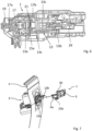
- Fig.1a represents a perspective view of a door panel skin 4 and a bracket 3 configured to be fixed to the inner side of the door panel skin 4.
- the door panel skin comprises a first 4a and a second 4b openings as well as a first 4c and a second 4d slots arranged respectively next to the first 4a and the second 4b openings.
- the slots 4c, 4d are directed towards a horizontal direction when the door panel skin 4 is assembled onto a vehicle and are configured for receiving screws 7 attached to the bracket 3 to enable the fixation of the bracket 3 to the door panel skin 4.
- Fig.2 represents the positioning of the screws 7 (pre-assembled to the bracket 3 on the side destined to be facing the door panel skin 4) in the openings 4a, 4b, next to the slots 4c, 4d.
- the screws 7 are then inserted into the slots 4c, 4d by displacing the bracket 3 laterally until the bracket 3 or the screws 7 come to a rest.
- the bracket 3 may comprise a pin 9 (or several) configured to come in contact with the door panel skin 4 to ensure the right lateral position of the bracket 3 when tightening the screws 7.
- a pin 9 or several
- the bracket 3 also comprises a deformable parallelogram mechanism 13 configured for moving between a retracted and a deployed position.
- Two opposite branches 13a, 13b of the parallelogram correspond to a first 13a and a second 13b levers configured for protruding through the first 4a and second 4b openings in the deployed position of the deformable parallelogram mechanism 13 as represented in Fig.2 and Fig.5 .
- Other parts of the deformable parallelogram mechanism 13 are more visible in Fig.6 .
- the first lever 13a is configured to rotate around a first axis 15a and the second lever 13b is configured to rotate around a second axis 15b.
- the first 13a and the second 13b levers are linked by rods 13c corresponding to a branch of the deformable parallelogram mechanism 13.
- the bracket 3 also comprises an actionable arm 17 (visible in Fig.6 ) configured for displacing the deformable parallelogram mechanism 13 from the retracted position to the deployed position.
- the actionable arm 17 is linked on its first end 17a to a mechanical actuator, a screw 19 in the present case, which is configured to displace the actionable arm in a first direction when the screw 19 is rotated in a first rotating direction and in a second direction opposite to the first direction when the screw 19 is rotated in a second rotating direction opposite to the first rotating direction.
- the actionable arm 17 is also configured to come in contact with the first lever 13a of the deformable parallelogram mechanism 13 at its second end 17b to push or pull on the said first lever 13a in order to displace the deformable parallelogram mechanism 13 from a retracted position to a deployed position.
- the actionable arm 17 is moved in the opposite direction (through the rotation of the screw in the opposite rotating direction)
- the deformable parallelogram is moved from its deployed position to its retracted position by the action of a return spring 21.
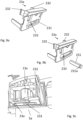
- the handle 5 comprises a first sleeve 5a configured for coming around the first lever 13a and a second sleeve 5b configured for coming around the second lever 13b.
- the handle 5 may be clipped to the first 13a and second 113b levers by a first 23a and a second 23b clips.
- the first clip 23a is configured to be positioned in a recess located in the first sleeve 5a on the side facing the ground when assembled to the vehicle.
- the second clip 23b is configured to be positioned in a recess located in the second sleeve 5b on the side facing the ground when assembled to the vehicle.
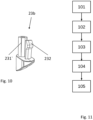
- the first clip 23a represented in Fig.9a and 9b , comprises an axis 231 configured to enable the rotation of the handle 5 with respect to the first lever 13a and the second clip 23b, represented in fig. 10 , comprises an axis 231' configured to enable the rotation of the handle 5 with respect to the second lever 13b.
- the first and second clips 23a and 23b also comprise clipping means 232 configured to cooperate respectively with the first and second sleeve 5a, 5b to prevent an axial displacement of the clips 23a, 23b and the associated axis 231, 231'.
- the first clip 23a is configured for blocking the relative displacement in the lateral direction (with respect to the vehicle direction) of respectively the first handle sleeve 5a with respect to the first lever 13a and the second clip 23b is configured for blocking the relative displacement in the lateral direction of respectively the second handle sleeve 5b with respect to the second lever 13b.
- the clipping means 232 may be made of a flexible rod with a hook at its extremal end.
- the first lever 13a comprises a hole 131 at its extremal end for receiving the axis 231 of the first clip 23a and the second lever 13b comprises a hole 131' at its extremal end for receiving the axis 231' of the second clip 23b.
- the first clip 23a comprise an oblong aperture 233 for receiving the first axis 231 of the first clip 23a so that the first axis may be displaced within the oblong aperture 233 as represented in fig.9a and 9b .
- the first axis 231 comprises a peripheral groove 231a with a reduced diameter and the oblong aperture 233 comprises a slot of reduced height where only the reduced diameter of the peripheral groove 231 can be introduced.
- the axis 231 is therefore introduced in the portion of the oblong aperture 233 having a large height and its peripheral groove is then slid in the slot.
- the axis 231 can then move laterally within the slot but cannot move axially.
- the end of the slot next to the portion of large height of the oblong aperture 233 may have an even smaller height to prevent the axis from getting out of the slot so that a predetermined force needs to be apply to the axis 231 to slide it into the slot.
- the axis 231 may be made in a different material than the rest of the first clip 23a.
- the axis 231 may be metallic, for example made of aluminium, whereas the rest of the clip may be made of plastics.
- the axis 231 is first positioned in the slot of the oblong aperture 233 of the first clip 23a and the first clip 23a is then positioned in the recess below the first sleeve 5a surrounding the first lever 13a, the axis 231 being configured to be positioned in the hole 131 of the first lever 13a as represented in Fig.9c .
- the axis 231' of the second clip 23b may be formed from the second clip 23b or may be made of a different material, for example, the axis 231' may be metallic and the rest of the second clip 23b may be made of plastics.
- the second clip 23b is for example overmolded.
- the second clip 23b also comprises clipping means 232.
- the first and the second lever 13a, 13b are configured so that the axis 231 and 231'of the first and the second clip 23a, 23b are parallel with each other. Furthermore, the axis 231, 231' are configured to be in a range of 20° around the vertical position, for example in the vertical position when assembled to the vehicle so that the handle 5 is displaced in a range of 20° around the horizontal direction when the handle 5 is moved from the retracted position to the deployed position.
- the vehicle door handle assembly 1 may also comprise an electrical actuator 29 (visible in Fig.6 ) such as an electrical motor 29 (visible in Fig.6 ) linked to the deformable parallelogram mechanism 13 in order to displace the handle 5 between the retracted position and the deployed position (the deployed and retracted position of the handle 5 may correspond to the deployed and retracted position of the deformable parallelogram mechanism 13).
- the handle 5 comprises for example a command button 50 on its outer side and a push on the said command button 50 by a user leads to the transmission of a command signal towards the electrical actuator 29 to deploy or retract the handle 5.
- the present invention also refers to a method for assembling a vehicle door handle assembly 1 on a door panel.
- Fig.11 is a flowchart of the different steps of the method.
- the first step 101 refers to the fixation of the bracket 3 on the inner side of the door panel skin 4.
- the door panel skin 4 may comprise two openings 4a, 4b through which the first 13a and second 13b levers of the bracket 3 may protrude.
- the fixation of the bracket 3 is for example achieved by two screws 7 pre-mounted on the bracket 3 and configured to be inserted respectively in a first 4c and a second 4d slots of the door panel skin 4.
- the first and second slots 4c, 4d are positioned respectively next to the two openings 4a, 4b.
- the second step 102 refers to the deployment of the first 13a and the second 13b levers of the bracket 4 through the first 4a and the second 4b openings of the door panel skin 4.
- Such deployment is achieved manually by rotating the screw 19 associated with the actionable arm 17 of the bracket 4 in a first rotating direction. Such rotation produces a displacement of the actionable arm 17.
- the deformable parallelogram mechanism 13 linked to the actionable arm 17 is then led towards the deployed position so that the first 13a and second 13b levers are displaced towards the outer side of the door panel skin 4 through the openings 4a, 4b.
- the screw 19 is rotated until it comes to a rest corresponding to the deployed position.
- the third step 103 refers to the positioning of the handle 5 on the first 13a and second 13b levers.
- the handle 5 is arranged so that the first sleeve 5a comes around the first lever 13a, the recess of the first sleeve 5a facing the hole 131 of the first lever 13a and so that the second sleeve 5b comes around the second lever 13b, the recess of the second sleeve 5b facing the hole 131' of the second lever 13b.
- the fourth step 104 refers to the clipping of the handle 5 to the first 13a and the second 13b levers.
- This step 104 comprises a first sub-step of introducing the axis 231 within the first clip 23a and more specifically the groove of the axis 231 within the slot of the first clip 23a.
- the second sub-step refers to the introduction of the first clip 23a in the recess of the first sleeve 5a and the insertion of the axis 231 in the hole 131 arranged in the first lever 5a.
- the third sub-step refers to the introduction of the second clip 23b in the recess of the second sleeve 5b and the insertion of the axis 231 in the hole 131' arranged in the second lever 13b.
- the first 13a and second 13b levers and the handle 5 may comprise electrical contacts so that the command button 50 is linked electrically to the electrical actuator 29 when the handle 5 is clipped to the bracket 3.
- the fifth step 105 refers to the positioning of the handle 5 back in the retracted position. Such positioning is obtained by rotating the screw 19 associated with the actionable arm 17 in the opposite direction.
- the deformable parallelogram mechanism 13 is brought back to the retracted position thanks to one or several return springs. In the retracted position, the handle 5 flushes with the outer side of the door panel skin 4.
- the use of a bracket 3 fixed directly on the door panel skin 4 and a handle 5 which is fastened to the bracket 3 from the outer side of the door panel skin 4 allow an easy and fast assembly and positioning of the door handle assembly 1.
- the clipping of the handle 5 allows a fast and secured fastening of the handle 5 to the bracket 3.
- the use of a deformable parallelogram mechanism 1 which can be displaced manually from a retracted position to a deployed position allowing the fixation of the handle 5 on the first 13a and second 13b levers of the bracket 3 corresponding to opposite branches of the deformable parallelogram mechanism 1 enables the fastening of the handle 5 on the bracket 3 without requiring the use of a electrical actuator which has to be supplied.
Landscapes
- Lock And Its Accessories (AREA)
Priority Applications (1)
| Application Number | Priority Date | Filing Date | Title |
|---|---|---|---|
| EP22168084.6A EP4261373A1 (de) | 2022-04-13 | 2022-04-13 | Fahrzeugtürgriffanordnung |
Applications Claiming Priority (1)
| Application Number | Priority Date | Filing Date | Title |
|---|---|---|---|
| EP22168084.6A EP4261373A1 (de) | 2022-04-13 | 2022-04-13 | Fahrzeugtürgriffanordnung |
Publications (1)
| Publication Number | Publication Date |
|---|---|
| EP4261373A1 true EP4261373A1 (de) | 2023-10-18 |
Family
ID=81308207
Family Applications (1)
| Application Number | Title | Priority Date | Filing Date |
|---|---|---|---|
| EP22168084.6A Pending EP4261373A1 (de) | 2022-04-13 | 2022-04-13 | Fahrzeugtürgriffanordnung |
Country Status (1)
| Country | Link |
|---|---|
| EP (1) | EP4261373A1 (de) |
Citations (5)
| Publication number | Priority date | Publication date | Assignee | Title |
|---|---|---|---|---|
| DE102013112041A1 (de) * | 2013-10-31 | 2015-04-30 | Dr. Ing. H.C. F. Porsche Aktiengesellschaft | Befestigungsvorrichtung |
| EP3274532A1 (de) * | 2015-03-25 | 2018-01-31 | Jaguar Land Rover Limited | Einziehbare griffanordnung |
| DE102018127805A1 (de) * | 2018-11-07 | 2020-05-07 | Huf Hülsbeck & Fürst Gmbh & Co. Kg | Türgriffanordnung für ein Kraftfahrzeug |
| EP3670797A1 (de) * | 2018-12-17 | 2020-06-24 | HUF Hülsbeck & Fürst GmbH & Co. KG | Türgriffanordnung eines kraftfahrzeugs |
| EP3763904A1 (de) * | 2018-03-09 | 2021-01-13 | Alpha Corporation | Türgriffvorrichtung für fahrzeuge |
-
2022
- 2022-04-13 EP EP22168084.6A patent/EP4261373A1/de active Pending
Patent Citations (5)
| Publication number | Priority date | Publication date | Assignee | Title |
|---|---|---|---|---|
| DE102013112041A1 (de) * | 2013-10-31 | 2015-04-30 | Dr. Ing. H.C. F. Porsche Aktiengesellschaft | Befestigungsvorrichtung |
| EP3274532A1 (de) * | 2015-03-25 | 2018-01-31 | Jaguar Land Rover Limited | Einziehbare griffanordnung |
| EP3763904A1 (de) * | 2018-03-09 | 2021-01-13 | Alpha Corporation | Türgriffvorrichtung für fahrzeuge |
| DE102018127805A1 (de) * | 2018-11-07 | 2020-05-07 | Huf Hülsbeck & Fürst Gmbh & Co. Kg | Türgriffanordnung für ein Kraftfahrzeug |
| EP3670797A1 (de) * | 2018-12-17 | 2020-06-24 | HUF Hülsbeck & Fürst GmbH & Co. KG | Türgriffanordnung eines kraftfahrzeugs |
Similar Documents
| Publication | Publication Date | Title |
|---|---|---|
| US5282657A (en) | Door handle assembly | |
| US8469412B2 (en) | Door handle device | |
| KR102155212B1 (ko) | 보우덴 케이블 | |
| KR100347877B1 (ko) | 브레이크와이어조립체단부클립을구비한제어장치 | |
| EP0375275A2 (de) | Fahrzeug-Türschlosssystem | |
| KR101479916B1 (ko) | 도어 장치 및 도어 장치를 위한 조립 방법 | |
| EP4261373A1 (de) | Fahrzeugtürgriffanordnung | |
| JP2000231862A (ja) | 電気的開閉装置とケーブル式連動装置とを備えた設備 | |
| US9761961B2 (en) | Lead-through terminal | |
| EP4261374A1 (de) | Fahrzeugtürgriffanordnung | |
| JP4184070B2 (ja) | ランプユニットの取付構造 | |
| EP3626921B1 (de) | Griffvorrichtung für ein fahrzeug | |
| EP3536884B1 (de) | Fahrzeuggriffvorrichtung | |
| US6626482B2 (en) | Vehicle door assembly | |
| US10794418B2 (en) | Bowden cable assembly | |
| EA003568B1 (ru) | Модуль размыкания, содержащий в себе вакуумный картридж и средство крепления, и электрическое коммутационное устройство, содержащее в себе такой модуль | |
| EP1972714B1 (de) | Türverschlussvorrichtung mit Notentriegelung, insbesondere für Haushaltsgeräte | |
| KR100535505B1 (ko) | 차량 도어 인사이드 핸들 로드의 압축 코일 스프링 적용구조 | |
| JP7477611B2 (ja) | 送電線のシールド導体のための接続デバイス | |
| EP3754781B1 (de) | Befestigungsanordnung einer antennenvorrichtung für ein fahrzeug | |
| EP3787384B1 (de) | Gleitschienenanordnung und haltemechanismus davon | |
| US20230313575A1 (en) | Vehicle door handle assembly | |
| CN216671235U (zh) | 用于车辆闩锁机构的线缆返回辅助组件 | |
| JPH04231715A (ja) | 調整可能なケーブル端部取付具 | |
| JP4176910B2 (ja) | 電気部品の取付構造 |
Legal Events
| Date | Code | Title | Description |
|---|---|---|---|
| PUAI | Public reference made under article 153(3) epc to a published international application that has entered the european phase |
Free format text: ORIGINAL CODE: 0009012 |
|
| STAA | Information on the status of an ep patent application or granted ep patent |
Free format text: STATUS: THE APPLICATION HAS BEEN PUBLISHED |
|
| AK | Designated contracting states |
Kind code of ref document: A1 Designated state(s): AL AT BE BG CH CY CZ DE DK EE ES FI FR GB GR HR HU IE IS IT LI LT LU LV MC MK MT NL NO PL PT RO RS SE SI SK SM TR |
|
| RAP3 | Party data changed (applicant data changed or rights of an application transferred) |
Owner name: MINEBEA ACCESSSOLUTIONS ITALIA S.P.A. |
|
| STAA | Information on the status of an ep patent application or granted ep patent |
Free format text: STATUS: REQUEST FOR EXAMINATION WAS MADE |
|
| 17P | Request for examination filed |
Effective date: 20240329 |
|
| RBV | Designated contracting states (corrected) |
Designated state(s): AL AT BE BG CH CY CZ DE DK EE ES FI FR GB GR HR HU IE IS IT LI LT LU LV MC MK MT NL NO PL PT RO RS SE SI SK SM TR |