EP4260751B1 - Befestigungsvorrichtung zum lösbaren verbinden eines befestigungselements mit einem bauteil - Google Patents
Befestigungsvorrichtung zum lösbaren verbinden eines befestigungselements mit einem bauteil Download PDFInfo
- Publication number
- EP4260751B1 EP4260751B1 EP23167019.1A EP23167019A EP4260751B1 EP 4260751 B1 EP4260751 B1 EP 4260751B1 EP 23167019 A EP23167019 A EP 23167019A EP 4260751 B1 EP4260751 B1 EP 4260751B1
- Authority
- EP
- European Patent Office
- Prior art keywords
- intermediate element
- blade
- locking blade
- stop
- housing
- Prior art date
- Legal status (The legal status is an assumption and is not a legal conclusion. Google has not performed a legal analysis and makes no representation as to the accuracy of the status listed.)
- Active
Links
Images


Classifications
-
- A—HUMAN NECESSITIES
- A44—HABERDASHERY; JEWELLERY
- A44C—PERSONAL ADORNMENTS, e.g. JEWELLERY; COINS
- A44C5/00—Bracelets; Wrist-watch straps; Fastenings for bracelets or wrist-watch straps
- A44C5/14—Bracelets; Wrist-watch straps; Fastenings for bracelets or wrist-watch straps characterised by the way of fastening to a wrist-watch or the like
- A44C5/145—Hooks
-
- A—HUMAN NECESSITIES
- A44—HABERDASHERY; JEWELLERY
- A44B—BUTTONS, PINS, BUCKLES, SLIDE FASTENERS, OR THE LIKE
- A44B11/00—Buckles; Similar fasteners for interconnecting straps or the like, e.g. for safety belts
- A44B11/006—Attachment of buckle to strap
-
- A—HUMAN NECESSITIES
- A44—HABERDASHERY; JEWELLERY
- A44C—PERSONAL ADORNMENTS, e.g. JEWELLERY; COINS
- A44C25/00—Miscellaneous fancy ware for personal wear, e.g. pendants, crosses, crucifixes, charms
-
- A—HUMAN NECESSITIES
- A44—HABERDASHERY; JEWELLERY
- A44C—PERSONAL ADORNMENTS, e.g. JEWELLERY; COINS
- A44C27/00—Making jewellery or other personal adornments
-
- G—PHYSICS
- G04—HOROLOGY
- G04B—MECHANICALLY-DRIVEN CLOCKS OR WATCHES; MECHANICAL PARTS OF CLOCKS OR WATCHES IN GENERAL; TIME PIECES USING THE POSITION OF THE SUN, MOON OR STARS
- G04B37/00—Cases
- G04B37/14—Suspending devices, supports or stands for time-pieces insofar as they form part of the case
- G04B37/1486—Arrangements for fixing to a bracelet
-
- A—HUMAN NECESSITIES
- A44—HABERDASHERY; JEWELLERY
- A44C—PERSONAL ADORNMENTS, e.g. JEWELLERY; COINS
- A44C5/00—Bracelets; Wrist-watch straps; Fastenings for bracelets or wrist-watch straps
- A44C5/18—Fasteners for straps, chains or the like
- A44C5/185—Attachment of fasteners to straps or chains
Definitions
- the present invention relates to a fastening device for removably connecting a fastening element to a component, such as a watch, jewelry or leather goods item.
- the invention relates in particular to a fastening device for connecting a bracelet to a watch case or two strands together by means of the fastening device.
- the present invention also relates to a method for mounting a fastening device.
- Watch straps consist of two strands attached to the watch case by means of a bar passing through a hole in the strap to connect it to the lugs of the case.
- a strand is a segment of the strap at least one end of which is connected to the watch case, sometimes through an intermediate piece or fastening device. The other end of each strand may be free, or connected, for example, to a strap clasp.
- the document FR2479667A1 describes a fixing device according to the preamble of claim 1.
- the document CH704810A1 describes a flexible bracelet strand intended to be removably attached to the bracelet attachment bar of a watch case.
- the bracelet strand has a flexible portion and a fastener.
- the document EP3838054A1 describes a device for attaching a bracelet, comprising a terminal body of the bracelet, a lock mounted on the terminal body, for sliding between a locking position, and an unlocking position.
- the present description relates to a fastening device intended to removably connect a fastening element, such as a bracelet strand, to a component, such as a watch, jewelry or leather goods item.
- the device comprises a first intermediate element intended to be fixed on the fastening element and comprising a fastening housing extending along a transverse axis and configured to cooperate with a fastening element intended to be fixed to the component.
- a second intermediate element is assembled in sliding connection with the first intermediate element, along a longitudinal axis substantially perpendicular to the transverse axis.
- the fastening device is configured to be in a locked position, in which the fastening element is fixed in the fastening housing, and an unlocked position allowing the release of the fastening element relative to the fastening housing, elastic means being provided to maintain the fastening device in the locked position.
- the second intermediate element is held assembled on the first intermediate element by a blade locking, the locking blade being housed in a blade housing provided in the first intermediate element and abutting, along the longitudinal axis, with a connecting stop provided on the first intermediate element. At least a portion of the locking blade and/or the connecting stop is elastically deformable so that the locking blade can be inserted into the blade housing.
- the present description also relates to a fastening device intended to removably connect a strand to a watch or leather goods component, comprising: a strand element (or first intermediate element) intended to be fixed on the strand and comprising a fastening housing, extending along a transverse axis and configured to cooperate with a fastening element intended to be fixed to the component.
- the fastening device also comprises a lock element (or second intermediate element) configured to be assembled in sliding connection with the strand element, along a strand axis (or longitudinal axis) substantially perpendicular to the transverse axis, so as to be secured to the strand element.
- the fastening device is configured to be in a locked position, in which the fastening element is fixed in the fastening housing, and an unlocked position allowing the release of the fastening element relative to the fastening housing.
- the fastening device comprises a locking blade comprising at least one portion elastically deformable in a direction out of the plane formed by the strand axis and the transverse axis.
- the lock element cooperates with the locking blade such that, when assembling the lock element with the strand element, the deformable portion is elastically deformed so as to pass over a stop element provided on the strand element and, when the lock element is secured, the locking blade abuts against the connecting stop, preventing the lock element from being detached from the strand element.
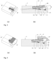
- the fastening device 100 comprises a first intermediate element 1 intended to be fixed on a strand (not shown), for example a bracelet or a strap.
- the first intermediate element 1 comprises a fastening housing 20, extending along a transverse axis A 20 and configured to cooperate with a fastening element (not shown) intended to be fixed to a component (not shown).
- the component may comprise a watch case or a buckle and the fastening element a bar.
- the strand may comprise a watch strap, a belt, or a leather goods strap.
- the first intermediate element 1 may be constitutive of the strand, overmolded in the strand, sheathed in a material of the strand, attached to the strand, or fixed to the strand.
- the fixing device 100 further comprises a second intermediate element 2 configured to be assembled in sliding connection with the first intermediate element 1 along a longitudinal axis A 10 , substantially perpendicular to the transverse axis A 20 so as to be assembled with the first intermediate element 1.
- the fixing device 100 further comprises a locking blade 3 of which at least one portion is elastically deformable.
- the second intermediate element 2 cooperates with the locking blade 3 such that, when assembling the second intermediate element 2 with the first intermediate element 1, the deformable portion of the locking blade 3 is elastically deformed so as to pass a connecting stop 11 provided on the first intermediate element 1.
- the locking blade 3 abuts against the connecting stop 11, preventing the second intermediate element 2 from being disassembled from the first intermediate element 1.
- elastic means may be arranged to maintain the second intermediate element 2 in its locked position.
- a return spring 4 may be arranged to push the second intermediate element 2 back into the locked position when no external force is exerted on the second intermediate element 2, as will be illustrated below.
- the locking blade 3 shows the locking blade 3 in isolation.
- the locking blade 3 has an opening 35 of length d in the direction of the longitudinal axis A 10 .
- the locking blade 3 has a distal arm 34 and a proximal arm 31 connected to the distal arm 34 by two lateral arms 33.
- the proximal arm 31 may have a notch 38 configured to cooperate with the connecting stop 11 as will be discussed below.
- the second intermediate element 2 comprises at least one drive stop 21 (see FIG. figure 1b ) configured to cooperate with the arm distal 34 so as to drive the locking blade 3 when assembling the second intermediate element 2 with the first intermediate element 1.
- the drive stop 21 is formed of two studs as illustrated in figure 1b .
- the second intermediate element 2 is shown inverted with respect to the axis A 30 in comparison with the second intermediate element 2 shown in the figure 1a .
- the lateral width of the two pads can correspond to the width between the two lateral arms 33.
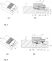
- FIGS. 3 to 6 illustrate sectional views at different stages of the assembly of the fixing device 100, according to one embodiment. More particularly, the Figures 3a and 3b show a perspective view ( Figure 3a ) and in section according to section AA on the Figure 3a ( Figure 3b ), of the fixing device 100 in the absence of the second intermediate element 2.
- the locking blade 3 is mounted in the first intermediate element 1 in a blade housing 12 provided in the first intermediate element 1.
- the locking blade 3 is mounted with the proximal arm 31 on the side of the fixing housing 20.
- the return spring 4 can be mounted in a bore 16 provided in the first intermediate element 1.
- the return spring 4 can also be formed integrally with the first intermediate element 1 or with the second intermediate element 2.
- the return spring 4 makes an angle ⁇ with the longitudinal axis A 10 , in a direction outside the plane A 30 (axis A 30 ) formed by the longitudinal axis A 10 and the transverse axis A 20 .
- This configuration of the return spring 4 makes it possible to produce a fixing device 100 which has a reduced thickness.
- the second intermediate element 2 is assembled on the fixing device 100.
- the second intermediate element 2 can be assembled in sliding connection with the first intermediate element 1.
- the second intermediate element 2 is positioned at the entrance of a guide rail 17, on the side of the fixing housing 20.
- the drive stop 21 is located at the level of the opening 35 and in the plane of the locking blade 3.
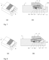
- FIGS. 5a and 5b which show a perspective view ( Figure 5a ) and in section according to section AA on the Figure 5a ( Figure 5b ), the fixing device 100 in which the second intermediate element 2 is moved along the longitudinal axis A 10 , in a direction away from the fixing housing 20 (shown by the arrow).
- the drive stop 21 located in the opening 35 engages with the distal arm 34.
- the drive stop 21 drives the locking blade 3 during its movement.
- the locking blade 3 is configured to be guided in a groove 13 provided on each side of the blade housing 12, when the locking blade 3 is driven by the second intermediate element 2.
- the locking blade 3 may comprise a sliding portion 39, provided on each of the lateral arms 33, and configured to be inserted and slide in the groove 13.
- the locking blade 3 When driven by the second intermediate element 2, the locking blade 3 is elastically deformed so as to pass over the connecting stop 11. More particularly, the proximal arm 31 of the locking blade 3 comes into contact with the connecting stop 11. The proximal arm 31 as well as the two lateral arms 33 are elastically deformed in the direction out of the plane A 30 , so that the proximal arm 31 passes over the connecting stop 11.
- the connecting stop 11 takes the form of a tooth comprising an inclined plane 111. When it passes, the proximal arm 31 presses on the inclined plane 111 until it passes to the other side of the connecting stop 11 which has a substantially straight side.
- FIG. 6a and 6b which represent a perspective view ( Figure 6a ) and in section according to section AA on the Figure 6a ( Figure 6b ), the locking blade 3 at the moment when the proximal arm 31 is almost above of the connecting stop 11.
- the figure 6 also shows the distal arm 34 of the locking blade 3 being guided in the groove 13 of the blade housing 12.
- a clearance 24 may be provided in the second intermediate member 2 to accommodate the deformed portion of the locking blade 3 as it deforms in the out-of-plane A direction 30 (see FIG. figure 1b ).
- FIGS. 7a and 7b show a perspective view ( Figure 7a ) and in section according to section AA on the Figure 7a ( Figure 7b ), of the fixing device 100 once the second intermediate element 2 is assembled with the first intermediate element 1.
- the locking blade 3 has passed over the stop element 11 and resumes its initial substantially flat shape in the blade housing 12.
- the proximal arm 31 of the locking blade 3 abuts against the connecting stop 11.
- the locking blade 3 is then trapped in the blade housing 12 and prevents the second intermediate element 2 from being disassembled from the first intermediate element 1.
- the notch 38 provided on the proximal arm 31 cooperates with the connecting stop 11 in order to keep the locking blade 3 aligned along the longitudinal axis A 10 .
- the second intermediate element 2 When the second intermediate element 2 is assembled with the first intermediate element 1, the second intermediate element 2 is movable relative to the first intermediate element 1 between a locked position, in which the fixing element is fixed in the fixing housing 20, and an unlocked position allowing the release of the fixing element relative to the fixing housing 20.
- figure 7 shows the fixing device 100 when the second intermediate element 2 is in the unlocked position.
- FIGS. 8a and 8b show a perspective view ( Figure 8a ) and in section according to section AA on the Figure 8a ( Figure 8b ), of the fixing device 100 once the second intermediate element 2 is assembled with the first intermediate element 1 and when the second intermediate element 2 is in the locked position.
- the return spring 4 is arranged to exert a return force pushing the second intermediate element 2 in the direction of the fixing housing 20, so that the second intermediate element 2 is in the locked position when no external force is exerted on the latter.
- the distal arm 34 abuts against the bottom 15 of the blade housing 12. Consequently, when the second intermediate element 2 is assembled with the first intermediate element 1, the length d of the opening 35 defines the free travel of the drive stop 21 in the opening 35 and therefore the travel of the second intermediate element 2 between the locked and unlocked positions.
- the fixing device 100 can be disassembled from the first intermediate element 1 by moving the second intermediate element 2 back in a direction towards the bottom 15 of the blade housing 12, so that the second intermediate element 2 does not cover the fixing housing 20 and to align the clearance 24 with the proximal arm 31 of the locking blade 3. In this position, it is then possible to lift the locking blade 3 (with a suitable tool) in order to pass the proximal arm 31 over the connecting stop 11 and to return the locking blade 3 to the initial mounting position of the Figures 3 and 4 .
- the clearance 24 being aligned with the proximal arm 31, the latter makes it possible to accommodate the locking blade 3 when it is deformed.
- the locking blade 3 and the second intermediate element 2 are then disassembled from the first intermediate element 1.
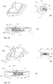
- Figures 9 and 10 show a perspective view of the fixing device 100 when the second intermediate element 2 is assembled with the first intermediate element 1 and when the second intermediate element 2 is in the unlocked position ( figure 9 ) and locked ( figure 10 ).
- the second intermediate element 2 comprises a tab 27 covering, when the second intermediate element 2 is in the locked position, at least part of the fixing housing 20 so as to prevent the fixing element from coming out of the fixing housing 20.
- the tab 27 In the unlocked position, the tab 27 is retracted opening the fixing housing 20 so that the fixing element can come out of the latter.
- the fixing device 100 can be configured so that, in the locked position, the tab 27 of the second intermediate element 2 covers the entire width L of the fixing housing 20 (see figure 9 ).
- the fastening device 100 may be configured such that, in the locked position, the tab 27 of the second intermediate element 2 covers only a portion of the width L of the fastening housing 20, for example, approximately half of the width L of the fastening housing 20. In this case, the travel of the second intermediate element 2 between the locked and unlocked positions may be reduced.
- the connecting stop 11 is elastically deformable so that, when the locking blade 3 is driven by the second intermediate element 2, the connecting stop 11 is elastically deformed.
- the locking blade 3 can be rigid.
- the locking blade 3 is driven while the second intermediate element 2 is slid.
- the locking blade 3 is arranged in the blade housing 12, prior to the engagement of the second intermediate element 2 in the first intermediate element 1.
- FIG 11 shows an exploded view of the fastening device 100, according to another embodiment.
- the locking blade 3 comprises a spring portion 32 configured, when the second intermediate element 2 is assembled, to deploy and compress along the longitudinal axis A 10 so as to cover at least a portion of the fastening housing 20.
- the spring portion 32 is configured to deploy and compress along the longitudinal axis A 10 , respectively, between a locked position, in which the fastening element is secured in the fastening housing 20, and an unlocked position allowing the release of the fastening element relative to the fastening housing 20.
- figure 12 shows an isolated view of the first intermediate element 1 or the first intermediate element 1 is inverted with respect to the representation of the figure 11 .
- the locking blade 3 also comprises a stop arm 31.
- the locking blade 3 comprises two stop arms 31 on each side of the spring portion 32.
- the stop arms 31 form the elastically deformable portion.
- the connecting stop takes the form of a stud 11 cooperating with each of the stop arms 31 in the blade housing 12 provided in the first intermediate element 1 (see figure 12 ). Note that the locking blade 3 could have only one stop arm 31.
- the locking blade 3 comprises a bolt 36 at its end on the side of the fixing housing 20.
- the second intermediate element 2 comprises a first blade stop 23 located on the side of the fixing housing 20, when the second intermediate element 2 is assembled with the first intermediate element 1, and a second blade stop 22, located on the opposite side of the second intermediate element 2.
- the locking blade 3 is assembled with the second intermediate element 2
- the locking blade 3 is constrained between the first and second blade stops 23, 22.
- the second intermediate element 2 is provided with a second blade housing 25 in which the locking blade 3 is received when it is assembled with the second intermediate element 2.
- the first blade stop is formed of two studs 23 cooperating with the bottom of a notch 37 provided on the spring portion 32 of the locking blade 3.
- the locking blade 3 is constrained between the first blade stop, formed by the two studs 23, and the second blade stop, formed by the opposite side 22 of the second blade housing 25.
- the second intermediate element 2 comprising the locking blade 3 is assembled in sliding connection with the first intermediate element 1.
- the second intermediate element 2 comprising the locking blade 3 is first placed on the first intermediate element 1 ( figure 15 ). In this position, the second intermediate element 2 and the locking blade 3 completely overlap the fixing housing 20.
- the bolt 36 which projects from the second intermediate element 2 bears against the edge of the fixing housing 20.
- the locking blade 3 can be compressed so that the bolt 36 is retracted inside the second intermediate element 2 ( figure 16 ) so as to lower the second intermediate element 2 into the blade housing 12 of the first intermediate element 1.
- figure 17a shows the second intermediate element 2 comprising the locking blade 3 mounted in the first intermediate element 1 when the bolt 36 is in the retracted position.
- figure 17b shows a detail of a section of the fixing device 100 at the assembly stage of the figure 17a , during which the locking blade 3 comes to bear on the connecting stop 11 provided on the first intermediate element 1.
- figure 17c shows a sectional and perspective view of the second intermediate element 2 mounted in the first intermediate element 1.
- the second intermediate element 2 is lowered into the bottom of the blade housing 12 of the first intermediate element 1, forcing the stop arm 31 of the locking blade 3 to deform in the direction out of the plane A 30 (shown by the dashed arrow at figure 18b ).
- THE Figures 17b And 18b correspond respectively to the AA cut at Figures 17a And 18a , view from a position shown by the arrow "V”.
- the figure 18c shows a view in section and perspective view of the second intermediate element 2 mounted in the first intermediate element 1.
- the second intermediate element 2 comprises a drive stop 21 configured to cooperate with the stop arm 31 so as to drive the locking blade 3 during assembly of the second intermediate element 2 with the first intermediate element 1.
- the second intermediate element 2 comprises a clearance 24 (see also FIG. figure 13 ) in order to accommodate the locking blade 3 when it deforms in the direction out of the plane A 30 .
- a projecting edge of the clearance 24 forms the drive stop 21 against which the stop arm 31 comes to bear (see the figures 13, 14 And 17b ).
- the first intermediate element 1 may comprise a guide rail 17.
- the second intermediate element 2 may comprise a guide rail counter-element 28 configured to cooperate with the guide rail 17.
- the second intermediate element 2 may also comprise a lip 29 configured to cooperate with a locking groove 19 provided on the rim 18 of the first intermediate element 1 (see the figures 12 , 19b and 19c ).
- FIGs 19a and 19b show the fixing device 100 when the second intermediate element 2 is pulled towards the bottom of the first intermediate element 1 (indicated by the arrow), i.e. in the direction away from the fixing housing 20.
- the locking blade 3 is driven in the same direction by the drive stop 21 of the second intermediate element 2.
- the figure 19b corresponds to the BB cut at the figure 19a .
- FIGs 20a and 20b show the fixing device 100 when the second intermediate element 2 comprising the locking blade 3 is assembled on the first intermediate element 1.
- the figure 20b corresponds to the CC cut at the figure 20a .
- the stop arm 31 abuts both against the connecting stop 11 of the first intermediate element 1 and the driving stop 21 of the second intermediate element 2.
- the locking blade 3 is thus fixed and prevents the second intermediate element 2 from disassembling from the first intermediate element 1.
- the figure 20c shows a sectional and perspective view of the second intermediate element 2 mounted in the first intermediate element 1.
- the spring portion 32 of the locking blade 3 comprises a stop finger 30 on each side of the spring portion 32.
- Each stop finger 30 is configured to come into abutment against a stop arm 31 when the second intermediate element 2 is assembled with the first intermediate element 1 and the spring portion 32 is compressed. This arrangement makes it possible to prevent the spring portion 32 from compressing beyond its elastic limit. Furthermore, the distance between the stop finger 30 and the stop arm 31 corresponds to the travel of the spring portion 32 between the locked and unlocked positions.
- the bolt 36 projects from the second intermediate element 2 so as to cover at least a portion of the fixing housing 20.
- the locking blade 3 can be configured so that the bolt 36 covers only a portion of the width L of the fixing housing 20, for example, approximately half of the width L of the fixing housing 20.
- the method of mounting the fixing device comprises the step of mounting the locking blade 3 in the second blade housing of the second element intermediate 2, prior to the engagement of the second intermediate element 2 in the first intermediate element 1.
- the locking blade 3 may be elastically deformable in a direction other than the direction out of the plane A 30 .
- the locking blade 3 may be elastically deformable along the longitudinal axis A 10 and/or transverse axis A 20 so as to pass around the connecting stop 11.
- the connecting stop 11 is elastically deformable so that, when the locking blade 3 is driven by the second intermediate element 2, the connecting stop 11 is elastically deformed.
- the stop arm 31 may be rigid.
- the fastening device 100 can also be configured to connect two strands together.
- the first intermediate element 1 can be fixed on one of the strands and the other strand is fixed to the fastening element.
Landscapes
- Physics & Mathematics (AREA)
- General Physics & Mathematics (AREA)
- Engineering & Computer Science (AREA)
- Manufacturing & Machinery (AREA)
- Clamps And Clips (AREA)
- Connection Of Plates (AREA)
Claims (19)
- Befestigungsvorrichtung (100), die dazu bestimmt ist, ein Befestigungselement, wie z. B. einen Strang eines Armband, abnehmbar mit einer Komponente , wie z. B. einem Uhren-, Schmuck- oder Lederwarenartikel, zu verbinden, wobei die Vorrichtung Folgendes umfasst:ein erstes Zwischenelement (1), das ausgerichtet ist, an dem Befestigungselement befestigt zu werden und das ein Befestigungsgehäuse (20) aufweist, wobei sich das Befestigungsgehäuse entlang einer Querachse (A20 ) erstreckt und so konfiguriert ist, dass es mit einem Befestigungselement, das ausgerichtet ist, an der Komponente befestigt zu werden, zusammenwirkt; undein zweites Zwischenelement (2), das mit dem ersten Zwischenelement (1) entlang einer Längsachse (A10 ), die im Wesentlichen senkrecht zur Querachse (A20 ) verläuft, in Gleitverbindung zusammengesetzt ist;wobei die Befestigungsvorrichtung (100) so konfiguriert ist, dass sie sich in einer verriegelten Position, in der das Befestigungselement in dem Befestigungsgehäuse (20) befestigt werden kann, und einer entriegelten Position, die das Lösen des Befestigungselements von der Befestigungsaufnahme (20) ermöglicht, befinden kann;dadurch gekennzeichnet, dassdas zweite Zwischenelement (2) durch eine Sperrklinge (3), die in einer in dem ersten Zwischenelement (1) vorgesehenen Klingenaufnahme (12) untergebracht ist, an dem ersten Zwischenelement (1) zusammengehalten wird, wobei die Sperrklinge (3) angeordnet ist mit dem zweiten Zwischenelement (2) zusammenzuwirken und entlang der Längsachse (A10 ) an einen an dem ersten Zwischenelement (1) vorgesehenen Verbindungsanschlag (11) anzustossen; unddass mindestens ein Teil der Sperrklinge (3) und/oder des Verbindungsanschlags (11) elastisch verformbar ist, was ein Einführen der Sperrklinge (3) in die Klingenaufnahme (12) ermöglicht.
- Die Befestigungsvorrichtung (100) nach Anspruch 1, wobei das zweite Zwischenelement (2) in Bezug auf das erste Zwischenelement (1) zwischen der verriegelten Position und der entriegelten Position verschiebbar ist.
- Die Befestigungsvorrichtung (100) nach Anspruch 2, bei der die Sperrklinge (3) eine Öffnung (35) mit einer Länge (d) entlang der Längsachse (A10 ) aufweist, wobei das zweite Zwischenelement (2) mindestens einen Mitnehmeranschlag (21) aufweist, der sich in der Ebene der Öffnung (35) bewegen kann, wobei die Länge (d) den Hub des zweiten Zwischenelements (2) zwischen der verriegelten und der entriegelten Position definiert.
- Die Befestigungsvorrichtung (100) nach Anspruch 3, wobei die Sperrklinge (3) in einer Richtung ausserhalb der Ebene (A30 ), die von der Längsachse (A10 ) und der Querachse (A20 ) gebildet wird, elastisch verformbar ist, so dass ein Anschlagarm (31) der Sperrklinge (3) beim Einführen der Sperrklinge (3) in die Klingenaufnahme (12) über den Verbindungsanschlag (11) hinweggehen und an den Verbindungsanschlag (11) anstoßen kann, wenn das zweite Zwischenelement (2) mit dem ersten Zwischenelement (1) zusammengesetzt ist.
- Die Befestigungsvorrichtung (100) nach einem der Ansprüche 1 bis 4, wobei die Klingenaufnahme (12) eine Nut (13) aufweist, die so gestaltet ist, dass sie mit einem Gleitabschnitt (39) zusammenwirkt, der an der Sperrklinge (3) vorgesehen ist und der es ermöglicht, die Sperrklinge zu führen, wenn sie in die Klingenaufnahme (12) eingeführt wird.
- Die Befestigungsvorrichtung (100) nach Anspruch 4 oder 5, wobei der Anschlagarm (31) eine Kerbe (38) aufweist, die so gestaltet ist, dass sie mit dem Verbindungsanschlag (11) zusammenwirkt, um die Sperrklinge (3) entlang der Längsachse (A10 ) auszurichten.
- Die Befestigungsvorrichtung (100) nach Anspruch 1, wobei die Sperrklinge (3) einen Federabschnitt (32) umfasst, der so konfiguriert ist, dass er sich entlang der Längsachse (A10 ) jeweils zwischen der verriegelten Position und der entriegelten Position ausdehnt und komprimiert.
- Die Befestigungsvorrichtung (100) nach Anspruch 7, wobei der elastisch verformbare Abschnitt mindestens einen Anschlagarm (31) der Sperrklinge (3) umfasst, so dass der Anschlagarm (31) beim Einführen der Sperrklinge (3) in die Klingenaufnahme (12) über den Verbindungsanschlag (11) hinweggehen und an den Verbindungsanschlag (11) anstoßen kann, wenn das zweite Zwischenelement (2) mit dem ersten Zwischenelement (1) zusammengesetzt ist.
- Die Befestigungsvorrichtung (100) nach Anspruch 7 oder 8, wobei das zweite Zwischenelement (2) einen ersten Klingenanschlag (23) und einen zweiten Klingenanschlag (22) umfasst, wobei die Sperrklinge (3) zwischen dem ersten und dem zweiten Klingenanschlag (23, 22) eingespannt ist, wenn das zweite Zwischenelement (2) mit der Sperrklinge (3) zusammenwirkt.
- Die Befestigungsvorrichtung (100) nach einem der Ansprüche 7 bis 9, wobei der Federabschnitt (32) einen Riegel (36) umfasst, der von dem zweiten Zwischenelement (2) so vorsteht, dass er zumindest einen Teil des Befestigungsgehäuses (20) abdeckt.
- Die Befestigungsvorrichtung (100) nach einem der Ansprüche 7 bis 10, wobei das erste Zwischenelement (1) eine Führungsschiene (17) umfasst, die so konfiguriert ist, dass sie mit einem Führungsschienen-Gegenelement (28), das an dem zweiten Zwischenelement (2) vorgesehen ist, zusammenwirkt.
- Die Befestigungsvorrichtung (100) nach einem der Ansprüche 8 bis 11, wobei der Federabschnitt (32) mindestens einen Anschlagfinger (30) aufweist, der so konfiguriert ist, dass er an den Anschlagarm (31) anstößt, wenn der Federabschnitt (32) zusammengedrückt wird;
wobei der Abstand zwischen dem Anschlagfinger (30) und dem Anschlagarm (31) dem Hub des Federabschnitts (32) zwischen der verriegelten und der entriegelten Position entspricht. - Die Befestigungsvorrichtung (100) nach einem der Ansprüche 1 bis 12, wobei das zweite Zwischenelement (2) eine Aussparung (24) aufweist, die so konfiguriert ist, dass sie den verformten Abschnitt der Sperrklinge (3) aufnimmt.
- Die Befestigungsvorrichtung (100) nach einem der Ansprüche 1 bis 13, die so konfiguriert ist, dass das zweite Zwischenelement (2) in der verriegelten Position nur einen Teil der Breite (L) des Befestigungsgehäuses (20) abdeckt.
- Armband mit mindestens einer Befestigungsvorrichtung (100) nach einem der Ansprüche 1 bis 14.
- Armbanduhr, die das Armband nach Anspruch 15 umfasst.
- Verfahren zum Montieren einer Befestigungsvorrichtung nach einem der Ansprüche 1 bis 14, das die folgenden Schritte umfasst:Teilweises Einrasten lassen der Sperrklinge in der Klingenaufnahme,Eingreifen lassen des zweiten Zwischenelements (2) in das erste Zwischenelement (1);Verschieben des zweiten Zwischenelements (2) in dem ersten Zwischenelement (1), wobei die Sperrklinge (3) von dem zweiten Zwischenelement (2) angetrieben wird, bis die Sperrklinge (3) in die Klingenaufnahme (12) eingreift und dabei an dem Verbindungsanschlag (11) anliegt;wobei mindestens ein Abschnitt der Sperrklinge (3) und/oder des Verbindungsanschlags (11) während des Einführens der Sperrklinge (3) in die Klingenaufnahme (12) elastisch verformt wird und in seine unverformte Form zurückkehrt, wenn die Sperrklinge (3) in die Klingenaufnahme (12) eingeführt wird.
- Montageverfahren nach Anspruch 17, bei dem die Sperrklinge (3) angetrieben wird, während das zweite Zwischenelement (2) verschoben wird.
- Montageverfahren nach Anspruch 17, wobei die Sperrklinge (3) in der Klingenaufnahme (12) montiert wird, bevor das zweite Zwischenelement (2) mit dem ersten Zwischenelement (1) in Eingriff kommt; oder
wobei das zweite Zwischenelement (2) eine zweite Klingenaufnahme (25) aufweist, in der die Sperrklinge (3) vor dem Eingriff des zweiten Zwischenelements (2) in das erste Zwischenelement (1) montiert wird.
Applications Claiming Priority (1)
| Application Number | Priority Date | Filing Date | Title |
|---|---|---|---|
| CH4242022 | 2022-04-13 |
Publications (2)
| Publication Number | Publication Date |
|---|---|
| EP4260751A1 EP4260751A1 (de) | 2023-10-18 |
| EP4260751B1 true EP4260751B1 (de) | 2024-11-06 |
Family
ID=87984610
Family Applications (1)
| Application Number | Title | Priority Date | Filing Date |
|---|---|---|---|
| EP23167019.1A Active EP4260751B1 (de) | 2022-04-13 | 2023-04-06 | Befestigungsvorrichtung zum lösbaren verbinden eines befestigungselements mit einem bauteil |
Country Status (2)
| Country | Link |
|---|---|
| EP (1) | EP4260751B1 (de) |
| CN (1) | CN116898189A (de) |
Family Cites Families (5)
| Publication number | Priority date | Publication date | Assignee | Title |
|---|---|---|---|---|
| FR2479667A1 (fr) * | 1980-04-03 | 1981-10-09 | Caplain Saint Andre Sa | Fermoir plat utilisable notamment comme fermoir de bracelet-montre |
| CH704810B1 (fr) | 2011-03-31 | 2015-08-14 | Louis Vuitton Malletier Sa | Brin de bracelet flexible. |
| US9498029B2 (en) * | 2015-03-13 | 2016-11-22 | Google Inc. | Clasp mechanisms for wristwatch bands |
| CH716976A1 (fr) | 2019-12-19 | 2021-06-30 | Richemont Int Sa | Dispositif d'attache de bracelet. |
| CN214509836U (zh) * | 2021-03-31 | 2021-10-29 | 东莞正源智能科技有限公司 | 一种表粒、表带及智能穿戴式设备 |
-
2023
- 2023-04-06 EP EP23167019.1A patent/EP4260751B1/de active Active
- 2023-04-13 CN CN202310392184.XA patent/CN116898189A/zh active Pending
Also Published As
| Publication number | Publication date |
|---|---|
| EP4260751A1 (de) | 2023-10-18 |
| CN116898189A (zh) | 2023-10-20 |
Similar Documents
| Publication | Publication Date | Title |
|---|---|---|
| EP2319349B1 (de) | Vorrichtung zum Befestigen eines Armbands auf einem Uhrengehäuse | |
| EP4059374B1 (de) | Armbandverschluss, der eine vorrichtung zur einstellung der länge des armbands umfasst, die eine rasche und bequeme anpassung ermöglicht | |
| EP3470935A1 (de) | Einrastsystem, beispielsweise zum festmachen eines armbands an einer armbanduhr | |
| CH715584A1 (fr) | Embout arrangé pour être fixé de façon amovible à une barrette. | |
| EP1841339B1 (de) | Entfaltbare schnalle für armband | |
| EP4260751B1 (de) | Befestigungsvorrichtung zum lösbaren verbinden eines befestigungselements mit einem bauteil | |
| EP3565431B1 (de) | Verbindungsvorrichtung für armband | |
| CH715870B1 (fr) | Système de fixation pour bracelets. | |
| EP4266942A1 (de) | Gurt | |
| EP4151116B1 (de) | Befestigungssystem für austauschbares band | |
| EP4486166B1 (de) | Element zur befestigung eines armbands an einem armbanduhrgehäuse | |
| EP3417734B1 (de) | Armbandverschluss, der eine reguliervorrichtung der länge des armbands umfasst | |
| CH695656A5 (fr) | Maillon réglable en longueur notamment pour bracelet à maillons. | |
| EP4238447A1 (de) | Faltverschluss | |
| WO2021209922A1 (fr) | Système de boucle interchangeable | |
| EP3641584A1 (de) | Bandverschluss mit einer vorrichtung zur anpassung der bandlänge | |
| CH719813A2 (fr) | Dispositif de fixation pour la fixation amovible d'un élément de bracelet sur une boite de montre et élément de bracelet comprenant le dispositif de fixation | |
| CH703680B1 (fr) | Dispositif de fixation ou d'accouplement rapide. | |
| EP3957205A1 (de) | Uhrkomponente, die mit einer kappe ausgestattet ist | |
| EP3918946B1 (de) | Vorrichtung zum befestigen eines armbands an einem armbanduhrgehäuse | |
| EP3918945B1 (de) | Armband für armbanduhr und vorrichtung zur befestigung eines solchen armbands | |
| EP1183958B1 (de) | Uhrarmbandverschluss | |
| CH652008A5 (fr) | Fermoir destine a relier les deux extremites d'un article souple formant une boucle. | |
| CH720024B1 (fr) | Connecteur pour fixer de manière amovible un bracelet à une boite de montre. | |
| EP4473862A1 (de) | Austauschbare schnallenvorrichtung |
Legal Events
| Date | Code | Title | Description |
|---|---|---|---|
| PUAI | Public reference made under article 153(3) epc to a published international application that has entered the european phase |
Free format text: ORIGINAL CODE: 0009012 |
|
| STAA | Information on the status of an ep patent application or granted ep patent |
Free format text: STATUS: THE APPLICATION HAS BEEN PUBLISHED |
|
| AK | Designated contracting states |
Kind code of ref document: A1 Designated state(s): AL AT BE BG CH CY CZ DE DK EE ES FI FR GB GR HR HU IE IS IT LI LT LU LV MC ME MK MT NL NO PL PT RO RS SE SI SK SM TR |
|
| STAA | Information on the status of an ep patent application or granted ep patent |
Free format text: STATUS: REQUEST FOR EXAMINATION WAS MADE |
|
| 17P | Request for examination filed |
Effective date: 20240409 |
|
| RBV | Designated contracting states (corrected) |
Designated state(s): AL AT BE BG CH CY CZ DE DK EE ES FI FR GB GR HR HU IE IS IT LI LT LU LV MC ME MK MT NL NO PL PT RO RS SE SI SK SM TR |
|
| GRAP | Despatch of communication of intention to grant a patent |
Free format text: ORIGINAL CODE: EPIDOSNIGR1 |
|
| STAA | Information on the status of an ep patent application or granted ep patent |
Free format text: STATUS: GRANT OF PATENT IS INTENDED |
|
| INTG | Intention to grant announced |
Effective date: 20240723 |
|
| GRAS | Grant fee paid |
Free format text: ORIGINAL CODE: EPIDOSNIGR3 |
|
| GRAA | (expected) grant |
Free format text: ORIGINAL CODE: 0009210 |
|
| STAA | Information on the status of an ep patent application or granted ep patent |
Free format text: STATUS: THE PATENT HAS BEEN GRANTED |
|
| AK | Designated contracting states |
Kind code of ref document: B1 Designated state(s): AL AT BE BG CH CY CZ DE DK EE ES FI FR GB GR HR HU IE IS IT LI LT LU LV MC ME MK MT NL NO PL PT RO RS SE SI SK SM TR |
|
| REG | Reference to a national code |
Ref country code: GB Ref legal event code: FG4D Free format text: NOT ENGLISH |
|
| REG | Reference to a national code |
Ref country code: CH Ref legal event code: EP |
|
| REG | Reference to a national code |
Ref country code: DE Ref legal event code: R096 Ref document number: 602023000921 Country of ref document: DE |
|
| REG | Reference to a national code |
Ref country code: IE Ref legal event code: FG4D Free format text: LANGUAGE OF EP DOCUMENT: FRENCH |
|
| REG | Reference to a national code |
Ref country code: LT Ref legal event code: MG9D |
|
| REG | Reference to a national code |
Ref country code: NL Ref legal event code: MP Effective date: 20241106 |
|
| PG25 | Lapsed in a contracting state [announced via postgrant information from national office to epo] |
Ref country code: HR Free format text: LAPSE BECAUSE OF FAILURE TO SUBMIT A TRANSLATION OF THE DESCRIPTION OR TO PAY THE FEE WITHIN THE PRESCRIBED TIME-LIMIT Effective date: 20241106 Ref country code: IS Free format text: LAPSE BECAUSE OF FAILURE TO SUBMIT A TRANSLATION OF THE DESCRIPTION OR TO PAY THE FEE WITHIN THE PRESCRIBED TIME-LIMIT Effective date: 20250306 Ref country code: PT Free format text: LAPSE BECAUSE OF FAILURE TO SUBMIT A TRANSLATION OF THE DESCRIPTION OR TO PAY THE FEE WITHIN THE PRESCRIBED TIME-LIMIT Effective date: 20250306 |
|
| PG25 | Lapsed in a contracting state [announced via postgrant information from national office to epo] |
Ref country code: NL Free format text: LAPSE BECAUSE OF FAILURE TO SUBMIT A TRANSLATION OF THE DESCRIPTION OR TO PAY THE FEE WITHIN THE PRESCRIBED TIME-LIMIT Effective date: 20241106 Ref country code: FI Free format text: LAPSE BECAUSE OF FAILURE TO SUBMIT A TRANSLATION OF THE DESCRIPTION OR TO PAY THE FEE WITHIN THE PRESCRIBED TIME-LIMIT Effective date: 20241106 |
|
| REG | Reference to a national code |
Ref country code: AT Ref legal event code: MK05 Ref document number: 1738367 Country of ref document: AT Kind code of ref document: T Effective date: 20241106 |
|
| PG25 | Lapsed in a contracting state [announced via postgrant information from national office to epo] |
Ref country code: BG Free format text: LAPSE BECAUSE OF FAILURE TO SUBMIT A TRANSLATION OF THE DESCRIPTION OR TO PAY THE FEE WITHIN THE PRESCRIBED TIME-LIMIT Effective date: 20241106 |
|
| PG25 | Lapsed in a contracting state [announced via postgrant information from national office to epo] |
Ref country code: ES Free format text: LAPSE BECAUSE OF FAILURE TO SUBMIT A TRANSLATION OF THE DESCRIPTION OR TO PAY THE FEE WITHIN THE PRESCRIBED TIME-LIMIT Effective date: 20241106 |
|
| PG25 | Lapsed in a contracting state [announced via postgrant information from national office to epo] |
Ref country code: NO Free format text: LAPSE BECAUSE OF FAILURE TO SUBMIT A TRANSLATION OF THE DESCRIPTION OR TO PAY THE FEE WITHIN THE PRESCRIBED TIME-LIMIT Effective date: 20250206 |
|
| PG25 | Lapsed in a contracting state [announced via postgrant information from national office to epo] |
Ref country code: LV Free format text: LAPSE BECAUSE OF FAILURE TO SUBMIT A TRANSLATION OF THE DESCRIPTION OR TO PAY THE FEE WITHIN THE PRESCRIBED TIME-LIMIT Effective date: 20241106 Ref country code: GR Free format text: LAPSE BECAUSE OF FAILURE TO SUBMIT A TRANSLATION OF THE DESCRIPTION OR TO PAY THE FEE WITHIN THE PRESCRIBED TIME-LIMIT Effective date: 20250207 Ref country code: AT Free format text: LAPSE BECAUSE OF FAILURE TO SUBMIT A TRANSLATION OF THE DESCRIPTION OR TO PAY THE FEE WITHIN THE PRESCRIBED TIME-LIMIT Effective date: 20241106 |
|
| PG25 | Lapsed in a contracting state [announced via postgrant information from national office to epo] |
Ref country code: PL Free format text: LAPSE BECAUSE OF FAILURE TO SUBMIT A TRANSLATION OF THE DESCRIPTION OR TO PAY THE FEE WITHIN THE PRESCRIBED TIME-LIMIT Effective date: 20241106 |
|
| PG25 | Lapsed in a contracting state [announced via postgrant information from national office to epo] |
Ref country code: RS Free format text: LAPSE BECAUSE OF FAILURE TO SUBMIT A TRANSLATION OF THE DESCRIPTION OR TO PAY THE FEE WITHIN THE PRESCRIBED TIME-LIMIT Effective date: 20250206 |
|
| PG25 | Lapsed in a contracting state [announced via postgrant information from national office to epo] |
Ref country code: SM Free format text: LAPSE BECAUSE OF FAILURE TO SUBMIT A TRANSLATION OF THE DESCRIPTION OR TO PAY THE FEE WITHIN THE PRESCRIBED TIME-LIMIT Effective date: 20241106 |
|
| PGFP | Annual fee paid to national office [announced via postgrant information from national office to epo] |
Ref country code: DE Payment date: 20250422 Year of fee payment: 3 |
|
| PG25 | Lapsed in a contracting state [announced via postgrant information from national office to epo] |
Ref country code: DK Free format text: LAPSE BECAUSE OF FAILURE TO SUBMIT A TRANSLATION OF THE DESCRIPTION OR TO PAY THE FEE WITHIN THE PRESCRIBED TIME-LIMIT Effective date: 20241106 |
|
| PG25 | Lapsed in a contracting state [announced via postgrant information from national office to epo] |
Ref country code: EE Free format text: LAPSE BECAUSE OF FAILURE TO SUBMIT A TRANSLATION OF THE DESCRIPTION OR TO PAY THE FEE WITHIN THE PRESCRIBED TIME-LIMIT Effective date: 20241106 |
|
| PGFP | Annual fee paid to national office [announced via postgrant information from national office to epo] |
Ref country code: FR Payment date: 20250425 Year of fee payment: 3 |
|
| PG25 | Lapsed in a contracting state [announced via postgrant information from national office to epo] |
Ref country code: RO Free format text: LAPSE BECAUSE OF FAILURE TO SUBMIT A TRANSLATION OF THE DESCRIPTION OR TO PAY THE FEE WITHIN THE PRESCRIBED TIME-LIMIT Effective date: 20241106 |
|
| PG25 | Lapsed in a contracting state [announced via postgrant information from national office to epo] |
Ref country code: SK Free format text: LAPSE BECAUSE OF FAILURE TO SUBMIT A TRANSLATION OF THE DESCRIPTION OR TO PAY THE FEE WITHIN THE PRESCRIBED TIME-LIMIT Effective date: 20241106 |
|
| PG25 | Lapsed in a contracting state [announced via postgrant information from national office to epo] |
Ref country code: CZ Free format text: LAPSE BECAUSE OF FAILURE TO SUBMIT A TRANSLATION OF THE DESCRIPTION OR TO PAY THE FEE WITHIN THE PRESCRIBED TIME-LIMIT Effective date: 20241106 |
|
| PG25 | Lapsed in a contracting state [announced via postgrant information from national office to epo] |
Ref country code: IT Free format text: LAPSE BECAUSE OF FAILURE TO SUBMIT A TRANSLATION OF THE DESCRIPTION OR TO PAY THE FEE WITHIN THE PRESCRIBED TIME-LIMIT Effective date: 20241106 |
|
| REG | Reference to a national code |
Ref country code: DE Ref legal event code: R097 Ref document number: 602023000921 Country of ref document: DE |
|
| PG25 | Lapsed in a contracting state [announced via postgrant information from national office to epo] |
Ref country code: SE Free format text: LAPSE BECAUSE OF FAILURE TO SUBMIT A TRANSLATION OF THE DESCRIPTION OR TO PAY THE FEE WITHIN THE PRESCRIBED TIME-LIMIT Effective date: 20241106 |
|
| PLBE | No opposition filed within time limit |
Free format text: ORIGINAL CODE: 0009261 |
|
| STAA | Information on the status of an ep patent application or granted ep patent |
Free format text: STATUS: NO OPPOSITION FILED WITHIN TIME LIMIT |
|
| 26N | No opposition filed |
Effective date: 20250807 |
|
| PG25 | Lapsed in a contracting state [announced via postgrant information from national office to epo] |
Ref country code: LU Free format text: LAPSE BECAUSE OF NON-PAYMENT OF DUE FEES Effective date: 20250406 |
|
| PG25 | Lapsed in a contracting state [announced via postgrant information from national office to epo] |
Ref country code: MC Free format text: LAPSE BECAUSE OF FAILURE TO SUBMIT A TRANSLATION OF THE DESCRIPTION OR TO PAY THE FEE WITHIN THE PRESCRIBED TIME-LIMIT Effective date: 20241106 |
|
| REG | Reference to a national code |
Ref country code: BE Ref legal event code: MM Effective date: 20250430 |
|
| PG25 | Lapsed in a contracting state [announced via postgrant information from national office to epo] |
Ref country code: BE Free format text: LAPSE BECAUSE OF NON-PAYMENT OF DUE FEES Effective date: 20250430 |