EP4259564B1 - Anlage und verfahren zur handhabung von kartonrollen - Google Patents
Anlage und verfahren zur handhabung von kartonrollen Download PDFInfo
- Publication number
- EP4259564B1 EP4259564B1 EP21848041.6A EP21848041A EP4259564B1 EP 4259564 B1 EP4259564 B1 EP 4259564B1 EP 21848041 A EP21848041 A EP 21848041A EP 4259564 B1 EP4259564 B1 EP 4259564B1
- Authority
- EP
- European Patent Office
- Prior art keywords
- reels
- reel
- unwinding
- stack
- station
- Prior art date
- Legal status (The legal status is an assumption and is not a legal conclusion. Google has not performed a legal analysis and makes no representation as to the accuracy of the status listed.)
- Active
Links
Images


Classifications
-
- B—PERFORMING OPERATIONS; TRANSPORTING
- B65—CONVEYING; PACKING; STORING; HANDLING THIN OR FILAMENTARY MATERIAL
- B65H—HANDLING THIN OR FILAMENTARY MATERIAL, e.g. SHEETS, WEBS, CABLES
- B65H19/00—Changing the web roll
- B65H19/10—Changing the web roll in unwinding mechanisms or in connection with unwinding operations
- B65H19/12—Lifting, transporting, or inserting the web roll; Removing empty core
- B65H19/123—Lifting, transporting, or inserting the web roll; Removing empty core with cantilever supporting arrangements
-
- B—PERFORMING OPERATIONS; TRANSPORTING
- B65—CONVEYING; PACKING; STORING; HANDLING THIN OR FILAMENTARY MATERIAL
- B65H—HANDLING THIN OR FILAMENTARY MATERIAL, e.g. SHEETS, WEBS, CABLES
- B65H19/00—Changing the web roll
- B65H19/10—Changing the web roll in unwinding mechanisms or in connection with unwinding operations
- B65H19/12—Lifting, transporting, or inserting the web roll; Removing empty core
-
- B—PERFORMING OPERATIONS; TRANSPORTING
- B65—CONVEYING; PACKING; STORING; HANDLING THIN OR FILAMENTARY MATERIAL
- B65H—HANDLING THIN OR FILAMENTARY MATERIAL, e.g. SHEETS, WEBS, CABLES
- B65H2301/00—Handling processes for sheets or webs
- B65H2301/40—Type of handling process
- B65H2301/41—Winding, unwinding
- B65H2301/417—Handling or changing web rolls
- B65H2301/41702—Handling or changing web rolls management and organisation of stock and production
-
- B—PERFORMING OPERATIONS; TRANSPORTING
- B65—CONVEYING; PACKING; STORING; HANDLING THIN OR FILAMENTARY MATERIAL
- B65H—HANDLING THIN OR FILAMENTARY MATERIAL, e.g. SHEETS, WEBS, CABLES
- B65H2301/00—Handling processes for sheets or webs
- B65H2301/40—Type of handling process
- B65H2301/41—Winding, unwinding
- B65H2301/417—Handling or changing web rolls
- B65H2301/4171—Handling web roll
- B65H2301/4173—Handling web roll by central portion, e.g. gripping central portion
-
- B—PERFORMING OPERATIONS; TRANSPORTING
- B65—CONVEYING; PACKING; STORING; HANDLING THIN OR FILAMENTARY MATERIAL
- B65H—HANDLING THIN OR FILAMENTARY MATERIAL, e.g. SHEETS, WEBS, CABLES
- B65H2301/00—Handling processes for sheets or webs
- B65H2301/40—Type of handling process
- B65H2301/46—Splicing
-
- B—PERFORMING OPERATIONS; TRANSPORTING
- B65—CONVEYING; PACKING; STORING; HANDLING THIN OR FILAMENTARY MATERIAL
- B65H—HANDLING THIN OR FILAMENTARY MATERIAL, e.g. SHEETS, WEBS, CABLES
- B65H2408/00—Specific machines
- B65H2408/20—Specific machines for handling web(s)
- B65H2408/24—Specific machines for handling web(s) unwinding machines
- B65H2408/241—Turret
-
- B—PERFORMING OPERATIONS; TRANSPORTING
- B65—CONVEYING; PACKING; STORING; HANDLING THIN OR FILAMENTARY MATERIAL
- B65H—HANDLING THIN OR FILAMENTARY MATERIAL, e.g. SHEETS, WEBS, CABLES
- B65H2701/00—Handled material; Storage means
- B65H2701/10—Handled articles or webs
- B65H2701/17—Nature of material
- B65H2701/176—Cardboard
Definitions
- the present invention relates to a plant and a process for handling cardboard reels.
- the present invention relates to the handling of cardboard reels to feed machines that produce cardboard tubes, especially for making paper rolls with an internal tubular core.
- logs of paper material from which rolls of toilet paper or kitchen paper rolls are obtained, involves feeding a web of paper, formed by one or more overlapping plies, along a predetermined path along which various operations are carried out before proceeding with the formation of the logs, including a transversal pre-incision of the web to form pre-cutting lines that divide it into tear-off sheets.
- the formation of the logs normally involves the use of cardboard tubes, commonly called “cores” on the surface of which a predetermined quantity of glue is distributed to allow the gluing of the paper web on the cores gradually introduced into the machine that produces the logs commonly known as "rewinder".
- Patent EP1700805 describes a rewinding machine which works according to the above indicated operating scheme.
- the logs thus produced are then conveyed to a storage unit which supplies one or more cutting-off machines by means of which the transversal cutting of the logs is carried out in order to obtain the rolls in the desired format.
- tubular cores are produced by means of machines commonly known as "tube-forming machines” configured to wind one or more cardboard webs around a mandrel creating a helical winding. Examples of tube mills configured in this way are provided in EP3099481 and EP3212391B .
- the main object of the present invention is to meet the above requirement.
- the present invention it is possible to automate most of the operations connected to the handling of the cardboard reels used to feed the tube mills, with both economic and technical advantages. From an economic point of view, the main advantages derive from a more efficient management of the personnel assigned to handling the cardboard reels and from the greater efficiency of the production process. From a technical point of view, the main advantages derive not only from automation, but also from greater operational precision and greater safety in the handling phases of the cardboard reels, avoiding risky manual interventions by the operators.
- a plant according to the present invention comprises:
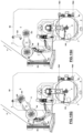
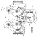
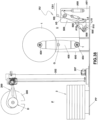
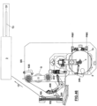
- FIG. 46 an arrangement is exemplified which provides for a single tube-forming machine (3) served by a plant in accordance with the present invention
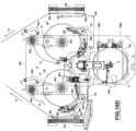
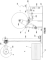
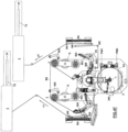
- Fig. 47 an arrangement is exemplified that provides two tube-forming machines (3) served by a plant in accordance with the present invention
- a cardboard tube (T3) produced by each tube-forming machine (3) is also schematically illustrated and the arrow "TF" indicates the exit of the tubes (T3) from the respective tube-forming machine (3).
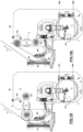
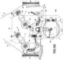
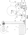
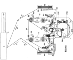
- Fig. 48 an arrangement is exemplified which provides a tube-forming machine (3) which receives the cardboard strips fed by two unwinding units to produce tubes formed by the superimposition of two strips rather than by a single cardboard strip.
- the reels (1) are formed by a predetermined amount of cardboard web wrapped around a central tubular core (1C).
- the stack (2) is formed by a predetermined number of superimposed reels (1).
- the tube-forming machines (3) are machines known per se, for example of the type described in the previously cited documents.
- the handling device (D) is configured to operate on the single reels (1) of the stack (2) set up in the loading station (P) to feed one or more tube-forming machines (3) which use the reels (1) to produce cardboard tubes.
- the handling device (D) is preferably configured and structured to facilitate the detachment of each reel (1) of the stack (2) from the underlying reel.
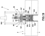
- a device comprises two coaxial ducts (4, 5) with an upper side and a lower side, connected to respective inlets (40, 50) for the introduction of compressed air which are arranged on a distributor (6) positioned on the upper side of the same ducts (40, 50).
- Each of said inputs (40, 50) is controlled by a respective solenoid valve (41, 51) which, in turn, is operated by means of a programmable control unit (7) as further described below.
- the duct (4) is inside the duct (5).
- the distributor (6) is mounted on the upper side of the external duct (5) by means of a bolt (65) which screws into the upper side of this duct.
- the inlets (40, 50) are radially oriented in the distributor (6) with respect to the coaxial ducts (4, 5) and are spaced apart by a predetermined value (h) thus forming an upper inlet (40) and a lower inlet (50) for compressed air.
- the upper inlet (40) is in communication with the internal duct (4), while the lower inlet (50) is in communication with the external duct (5).
- the lower base (60) of the distributor (6) is integral with the upper base (80) of a box-like body (8) which is crossed by the tubular ducts (4, 5) and has a lower base in the form of a flange (81).
- the box-shaped body (8) is integral with a maneuvering portion (800) which can be moved to and from the stack (2) by means of a movement arm (200) as further described below.
- said operating portion (800) is formed by a plurality of vertical rods (801) which connect an upper flange (802) to the lower flanged base (81) of said body (8), so as to contain the latter and the distributor (6) inside it.
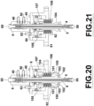
- the upper plate (91) includes a fixed upper flange (911) keyed on the rod (45), a movable lower flange (912) able to slide on the rod itself (45), and an elastic gasket (913) positioned between the fixed upper flange (911) and the lower movable flange (912) coaxially to the rod (45).
- the lower plate (92) comprises a fixed lower flange (921) integral with the lower end of the rod (45), a movable upper flange (922) able to slide on the rod (45), and an elastic gasket (923) positioned between the fixed lower flange (921) and the movable upper flange (922) coaxially to the rod (45).
- the fixed lower flange (921) is blocked on the lower end of the rod (45) by means of a bolt (95).
- the outlet (42) of the internal duct (4) is between the movable flanges (912, 922) of the plates (91, 92).
- the drawings also show two ducts (420) that pneumatically connect the movable flanges (912, 922) with the outlet (42) of the duct (4).
- the movable flanges (912, 922) move in the direction of the respective fixed flanges (911, 921), each compressing the corresponding elastic gasket (913, 923) which, consequently, is forced to expand radially outwards.
- the gaskets (913, 923) are made of silicone rubber or para rubber, which is rubber with a hardness between 20 Shore A and 40 Shore A.
- the fixed lower flange (920) has a lower conical surface (924) which favors its insertion into the cores (1C) of the stacked reels (1).
- said conical surface is a perimeter surface that delimits an internal concave cavity (925) whose function is described below.
- the plates (91, 92) have an elastically expandable portion in the radial direction (the portion that in the example described above consists of the respective gaskets) when compressed air is introduced into the internal duct (4).
- the outlet (52) of the external duct (5) is in correspondence with a space (S) present between the movable flanges (912, 922) of the plates (91, 92).
- the external duct (5) is used to pressurize a space (S) between the plates (91, 92).
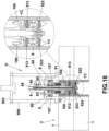
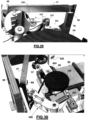
- the device (D) shown by way of example in Figs. 17-27 also comprises a mechanism suitable for engaging the internal surface of the cores (1C) of the reels (1).
- this mechanism comprises a plurality of jaws (100) consisting of levers in the shape of an inverted "L” with a toothed front side (101), a rear side (102) constrained to a bushing (104) able to slide on the surface external duct (5), and an intermediate part pivoted on a pin (103) oriented perpendicular to the surface of a casing (880) developed under the flanged part (81).
- Said casing has suitable openings (881) to allow the jaws (100) to come out.
- the upper part of the bushing (104) has a flange (105) which, in cooperation with a cup-shaped lower appendix (82) of the lower base (81) of the box-shaped body (8), defines a housing for an elastic element (106) invested coaxially on the bushing (104).
- the flange (105) arranged on the upper part of the bushing (104) is integral with a piston (107) arranged between the same flange (105) and the upper base (80) of the box-like body (8).
- the upper base (80) of the box-like body (8) has an inlet (83) for the introduction of compressed air into it.
- the piston (107) is lowered, overcoming the resistance of the elastic element (106) and causing the lowering of the bushing (104), meaning the approach of the toothed sides of the levers (100) to the bushing (104).
- the inlet (83) is also controlled by a solenoid valve (830) operated by the control unit (7).
- the drawings also show two ducts (420) that pneumatically connect the movable flanges (912, 922) with the outlet (42) of the duct (4).
- the whole part of the device (D) underneath the flanged part (81) will also be called the “engagement part” (ED) of the device (D).
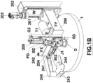
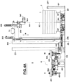
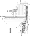
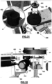
- the device (D) described above can be mounted on a handling arm (200) which allows it to be moved to and from the stack (2) set up in the reel loading station (P) (1) as indicated by the double arrow "M" in Fig.4A .
- the reference “AC” indicates the axis of the reels (1).
- the arm (200) is provided with a carriage (201) sliding on a column (202).
- the carriage (201) is connected to an electric motor (203), arranged on the column (202), by means of a screw-nut screw connection (W).
- the electric motor (203) controls the movement of the arm (200) to and from the stack (2).
- the length of the arm (200) is selected in such a way that the device (D) is moved to and from the stack (2) along the aforementioned axis (AC).
- the column (202) is mounted on a revolving base (206) whose rotation is controlled by a corresponding electric motor (207).
- the rotation axis of the swivel base (206) is indicated by the reference "A6". Therefore, the arm (200) can be moved along the direction indicated by the double arrow "M", parallel to the column (202), and can be rotated around the axis (A6) of the rotating base (206). By coordinating these movements, the arm (200) can therefore travel along a predetermined trajectory, in particular a transport trajectory of the reels from the loading point (P) to the unwinding station (U).
- the arm (200) carries, on its side opposite to the side attached to the carriage (201), a vertical guide (G2) on which a secondary carriage (204) slides, operated by a corresponding pneumatic actuator (205) which, in turn, is bound to said guide (G2).
- the device (D) for moving the cores is supported by the secondary carriage (204): the first carriage (201) moves the arm (200) towards the stack (2) for a section of predetermined length and subsequently the second carriage (204) operated by the actuator (205) intervenes and moves the device (D) until it comes into contact with the highest reel of the stack (2).
- the contact of the device (D) with the highest reel of the stack (2) is detected by a proximity sensor (SD) mounted on the bottom of the device (D).
- SD proximity sensor
- a tank (T1) is mounted on the arm (200) in which compressed air is stored to feed the pneumatic actuator (205) and always make the compressed air readily available that can be used to pressurize the space (S) previously mentioned.
- the device (D) for moving the reels is connected to the secondary carriage (204) by means of a bracket (S8) connected to the flange (802) of the device (D) by means of a spherical joint (J1). In this way, the device (D) is connected to the secondary carriage (204) and to the first carriage (201), so it can be moved vertically according to the direction indicated by the double arrow "M", but is free to swing around the joint (J1).
- the device oscillation detection mechanism (D) can consist of a pin (PD) projecting centrally from the upper flange (802) of the same device (D) and two photocells (FX, FY) oriented with the respective optical axes orthogonal to each other and supported by a bracket (BD) fixed to the secondary carriage at a predetermined distance from the flange (802).
- the pin (PD) is connected to the flange (802) by means of two stems (GP) fixed on the upper side of the same flange (802).
- the optical axes of the photocells (FX, FY) intercept the pin (PD).
- the photocells (FX, FY) each detect a predetermined reference distance from the pin (PD), while if the device (D) is inclined the said photocells detect a variation with respect to the reference distance. Said variation is assumed to be indicative of the inclination of the device (D) with respect to the vertical.
- the detections of the photocells (FX, FY) i.e. the detections of the mechanism for detecting the inclination of the device (D) with respect to the vertical, can be used to control the position of the platform (PP) as further described below.
- the core surface engagement mechanism (1C) can be omitted.
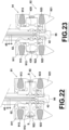
- Fig. 27 shows a further embodiment of the invention, in which the device (D) is equipped with a suction cup (300) to engage the upper face (10) of the upper reel of the stack (2) instead of engaging its core (1C) as in the example previously described.
- the suction cup (300) is formed by a discoidal extension of the body (8) equipped with sealing gaskets (301) formed on the lower side of the same extension.
- An aspirator (302) is mounted on the upper side of the suction cup (300) to produce a vacuum in the space that forms between the reel (1) and the suction cup (300).
- the device described above if it also includes the core engagement mechanism (1C), can be used as follows.
- the box-like body (8) with its lower base (81) is placed in contact with the upper base of the reel (1) which is higher than the stack (2).
- the upper plate (91) is inside the core (1C) of the reel (1) with which said base (81) is in contact, while the plate (92) is inside the core (1C) of the underlying reel.
- the distance (k) between the plates (91, 92) is such that, once the base (81) is placed against the upper face of the reel (1) higher than the stack (2), the plates (91, 92) are one inside this reel and the other inside the underlying reel.
- compressed air is introduced through the inlet (83), for which the levers (100) are set back, means closer to the bushing (104).
- the interruption of the compressed air supply through the inlet (83) arranged on the box-like body (8) causes the lifting of the bushing (104), pushed upwards by the elastic member (106), and therefore the rotation of the levers (100) on the pins (103), whereby the toothed sectors (101) of the same levers (100) move away from the bushing (104) and engage the inner surface of the core (1C) of the upper reel of the stack (2).
- the top reel (1) of the stack (2) is engaged by the arm (800) through the engagement mechanism which, in the example described above, is the mechanism comprising the levers (100).
- the arm (200) can then be led to an unwinder (30) with the reel (1) hooked to it.
- the release of the reel will be determined by a new introduction of compressed air through the inlet (83) which will cause the levers (100) to approach the bushing (104) and therefore the disengagement of the toothed sector of the same levers from the internal surface of the relative core (1C).
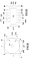
- the platform (PP) is a horizontal platform configured to be moved parallel to itself, that is along two mutually orthogonal directions (x, y) in the plane of the same platform, and is connected to respective handling means (PMX, PMY) which allow to move it along said directions (x, y) in order to center the reels (1) with respect to the manipulator arm (200).
- the means (PMX, PMY) for moving the platform (PP) consist, for example, of two gearmotors. These gearmotors can be connected to the lower surface of the platform (PP) by means of corresponding lever mechanism (LX, LY) fixed to the lower surface of the platform (PP) through respective connection flanges (CX, CY).
- the platform (PP) preferably rests on four columns (CP) that keep it at a distance from the base (BS) of the system. Between each column (CP) and the platform (PP) there is a sphere (SF) which favors the movement of the platform on the columns (CP) along the aforementioned directions (x, y).
- two beams (BP) are mounted on the upper face of the platform (PP) on which the stack (2) is placed, so that between the stack itself and the upper face of the platform (PP) there is a space of predetermined height.
- said beams (BP) are arranged parallel to each other.
- the platform (PP) can be moved along the direction (x) and/or along the direction (y) until the stack (2) is correctly centered with respect to the device (D).
- the gearmotors (PMX, PMY) are preferably controlled by a programmable control unit (CU) which receives signals from the aforementioned photocells (FX, FY) and operates the same gearmotors according to the signals emitted by the photocells, thereby controlling the movement of the platform (PP) in the plane defined by the directions (x, y) as previously mentioned, that is, by adjusting the position of the platform (PP) in such a way as to determine the correct centering of the stack (2) with respect to the device (D).
- CU programmable control unit
- a movable arm (240) controlled by a corresponding pneumatic actuator (241) constrained to the same carriage (204).
- Said arm (240) is connected to one side of the secondary carriage (204) by means of a vertical axis hinge (242) and has, on the opposite side, a fork (243) formed by two horizontal plates spaced apart by a corresponding value at the height of the individual reels (1).
- the actuator (241) controls the rotation of the arm (240) around the axis of the hinge (242).
- the arm (240) is made to rotate, starting from a spaced position, towards the reel engaged by the movement control device (D) in such a way that the plates of the fork (243) are one below and one above the same reel. In this way, the risk of falling of the reel (1) moved by the handling device (D) is reduced.
- the arm (240) constitutes a safety device that holds the reel (1) while the latter is being moved.
- the arm (240) is brought back to its initial position distanced from the device (D) by disengaging the reel (1).
- an elastic appendix (244) is mounted on a front part of each plate of the fork (243) which forms an invitation to the entry of the reel (1) between the same plates when the arm (240) is approached to the device (D).
- the aforementioned gearmotors (PMX, PMY) are also controllable, by means of the programmable control unit (CU), by means for controlling an initial position of the platform (PP) to ensure that the axis (AC) of the reels (1) that form the stack (2) is aligned with the central axis (A9) of the handling device (D) arranged in the position for picking up a reel.
- CU programmable control unit
- said means for controlling the initial position of the platform (PP) are optical control means arranged in fixed positions on two sides of the same platform.
- these optical control means are formed by a first pair of photocells (CFX) placed on a first horizontal bar (HFX) at a predetermined height from the base (BS) of the system and a second pair of photocells (CFY) placed on a second horizontal bar (HFY) at the same height as the first pair of photocells with respect to the base (BS) of the system.
- the first horizontal bar (HFX) is oriented parallel to the aforesaid direction (x), while the second horizontal bar (HFY) is oriented parallel to the aforesaid direction (y), so that the photocells (CFX) of the first pair result with their respective axes optics oriented orthogonally to the optical axes of the photocells (CFY) of the second pair.
- the bars (HFX, HFY) are mounted on respective fixed support columns (SX, SY) each placed at a predetermined distance from the platform (PP).
- the distance between the photocells (CFX) of the first pair is equal to the distance between the photocells (CFY) of the second pair.
- the means for controlling the initial position of the platform (PP) can be configured and positioned in a different way from what is exemplified above, cooperating with the control unit (CU) to control the initial position of the platform (PP) by moving it in such a way as to align the axis (AC) with the axis (A9).
- the stack (2) of reels (1) is positioned on the platform (PP) by means of a forklift (MU) operated by an operator.
- the reels (1) are normally stacked on a pallet (P2) that can be loaded on the forks (FM) of the forklift.
- the operator can be assisted by photocells (CFX, CFY).
- the measurements performed by these photocells can be used to send signals to a display (MC) designed to display suitable graphic indications (GM) in response to the measurements of the photocells (CFX, CFY) which guide the operator in positioning the pallet on the platform (PP).
- the photocells (CFX, CFY) detect the position of the stack of reels present on the pallet with respect to the platform and send detection signals to the control unit (CU) which in turn drives the monitor (MC).
- Graphic indications appear on the latter (for example, red or green circles aligned according to two mutually orthogonal directions) which suggest the operator to maneuver the forklift in such a way as to center the pallet on the platform (PP), albeit not extremely precisely.
- the display (MC) is shown, set up at a height, with respect to the base of the system, suitable for allowing it to be viewed by the operator operating the forklift.
- the same figures show the graphic indications (GM) shown on the display (MC).
- the positioning of the stack (2) of reels on the platform (PP) can be carried out by means of a self-propelled trolley with automatic guidance of the type known per se.
- At least one unwinding unit (UU) is arranged in the unwinding station (U).
- two unwinding units (UU) are arranged side by side in the unwinding station (U), i.e. positioned at a predetermined distance from each other.
- Figs. 3 and 4B-11B only one unwinding unit (UU) is shown for simplification.
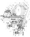
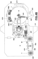
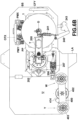
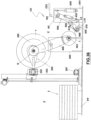
- Each unwinding unit (UU) comprises a carousel structure (G) with a horizontal beam (400) enslaved to a gearmotor (401) which controls its rotation around a respective central vertical axis (AU).
- the gearmotor (401) is placed on a corresponding base (402) so as to keep the beam (400) at a predetermined height with respect to the base (BS) of the system.
- Two supports (403) are arranged on the beam (400) in diametrically opposite positions with respect to said axis (AU).
- the supports (403) consist of horizontal plates each of which has a central through hole.
- each support (403) there is a pin with a vertical axis (404) which, being operated by a respective pneumatic actuator with a vertical axis (405) and being arranged in a central position with respect to the corresponding support (403), is free to pass through the central hole of the same support and can assume an extracted position (in which it protrudes above the support 403) and a retracted position (in which it is below the support 403).
- both pins (404) are extracted.
- the pin (404) has a convex upper surface to facilitate its contact with the concave surface (925) of the pick-up and handling device (D) when positioning the reels (1) on the supports (403) as further described in following.
- the actuator (405) of each pin (404) is constrained to the lower face of the beam (400) by means of a horizontal plate (406) which is connected to the lower face of the beam (400) through several vertical rods (407) which hold the same plate (406) at a predetermined distance from the beam (400). The ends of the rods (407) are screwed to the plate (406) on one side and to the beam (400) on the other side.
- the actuator (405) is constrained to the lower face of the plate (406).
- a coaxial brake disc (D40) is mounted on the hub (M40) of the support (403).
- two pneumatic actuators with vertical axis (410) whose stems act on the lower face of the disc (408) so that the latter can be moved, along the direction of the rods (407), from and towards the respective support (403) and then moved to and from the brake disc (D40) so that during braking the insert (409) can come into contact with the brake disc (D40).
- each plate (406) is integral with the lower face of the beam (400), to which it is connected by means of the rods (407) which also act as guides for the movement of the disc (408) controlled by the actuators (410) mounted on the upper face of the plate (406).
- the supports (403) are free to rotate around their respective central axes (A4).
- Fig.12E shows a bearing (411) coaxial to the pin (404) which allows the support (403) to rotate idly around the same pin whose longitudinal axis coincides with the central axis (A4) of the support.
- a wheel with a vertical axis (413) operated by a respective electric actuator (414) which serves to rewind the cardboard strips after their cutting as further described below.
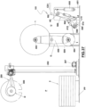
- the rotation of the beam (400) around the axis (AU) allows, as further described below, to arrange the supports (403) alternatively in the unwinding position, position in which the web fed by the reel (1) arranged on a support, and in a waiting position or in a position in which the support can receive a new reel without interrupting the web unwinding from the reel present on the support arranged in the unwinding position.
- the rotation of the beam (400) around the axis (AU) allows the exchange of the positions of the supports (403).
- the reference "W” indicates a first position of waiting and initial unwinding of a support (403) of a carousel (G), that is, the position closest to the station (P), while the reference “Y” indicates a second position for unwinding and exhaustion of the other support of the same carousel.
- the arrangement of several supports (403) on the carousel (G) allows, as further described below, to ensure the continuity of the feeding process of the tube-forming machines with the strips unwound by the reels (1) even during the reel exchange phases in exhaustion with unused reels.
- the carousel (G) is rotated around the axis (AU) so that this support is moved away from the first position (Y) while another support (403) takes its place.
- the provision of several supports (403) on the carousel (G) ensures the possibility of performing an exchange of positions between the supports themselves which determines a corresponding exchange of positions of the reels (1) intended to feed the cardboard strips with which the tube-forming machines make cardboard tubes.
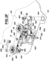
- each carousel (G) there is a mechanism (DS) configured to guide the cardboard strips that unwind from the reels (1) present on the aforementioned supports (403) in order to temporarily modify their path in the phases of exchange of positions of the same supports and also configured to perform further functions as further described below.
- said mechanism (DS) comprises an arm (500) mounted on a column (501) by means of a vertical axis hinge (V5) and enslaved to a pneumatic actuator (502) which controls its rotation around said axis (V5).
- the actuator (502) is fixed to the column (501).
- the latter is arranged at a predetermined distance from the respective carousel (G) in a rearward position with respect to the corresponding carousel (G).
- the columns (501) are positioned on corresponding lateral appendages (LA) of the base (BS).
- the arm (500) has a rear side (R5), constrained to the column (501) as previously mentioned, and a front side (F5) and is preferably made up of two horizontal plates (503, 504) spaced apart by a predetermined value to form an intermediate space (HS).
- an idle roller with a vertical axis (512) cooperating with the blade (510) and a convex strip-guide surface (513) placed on the opposite side of the roller (512) with respect to the blade (510).
- a vertical axis pneumatic actuator (514) is constrained to the lower face of the lower plate (504) of the arm (500) by means of a corresponding bracket (515) which has a vertical portion integral with the lower face of the plate (504) and a horizontal portion on which the actuator (514) is fixed.
- the stem of the latter passes through a hole formed in the horizontal part of the bracket (515) and a horizontal plate (516) is fixed on the same stem which, consequently, can be placed in a raised position (position in which it is at the same height of the lower plate 504 of the arm 500) and a lowered position (position in which it is at a lower height than the plate 504).
- the actuator (514) controls the lowering and lifting of the plate (515).
- the latter is constrained to a vertical guide (520) integral with the lower face of the lower plate (504) of the arm (500).
- the arm (518) is constrained by means of a pin with a vertical axis on the upper face of the plate (515) and can rotate around this axis being enslaved to a respective actuator (522) supported by the same plate (515). In this way, also the group formed by the idle roller (517) and the arm (518) is enslaved to the actuator (514).
- the plate (516) is raised, while in Figs.13C-13D the same plate is in the lowered position.
- a photocell (523) is mounted to the side of the aforesaid position (Y) and is configured to optically detect the diameter of the reel mounted on the support (403) which occupies said position.
- Said photocell (523) is mounted on a corresponding column (524) which supports it at a suitable height for said detection by means of a bracket (525). Mounted on the same bracket (525) is a plate (526) spaced by a predetermined value from the photocell (523).
- the column (524) is arranged downstream of the position (Y) with respect to the direction of rotation (RG) of the carousel (G).
- CV in the drawings indicates a hollow column through which electrical cables and compressed air ducts connected to the various actuators described above pass.
- Procedures which can be carried out by means of an implant according to the present invention are described below using reels (1) on the lateral surface of which, in a per se known manner, a piece of double-sided adhesive tape (BA) is applied.
- the double-sided tape (BA) is applied near the initial edge of the reel itself so as to also perform the function of keeping this edge adhering to the underlying material of the reel until the moment in which the reel must be used to feed a tube-forming machine, or until the time of the joining phase described below.
- the device (D) is lowered to determine the entry of its conical part (924) into the core (1C) of this reel.
- the tilt detection mechanism (D) which in this case oscillates on the joint (J1), and the platform (PP) is moved along the aforementioned directions (x, y) by means of the actuators (PMX, PMY), according to the readings of the photocells (FX, FY), until the axes are aligned (AC) and (A9), that is until an alignment condition is achieved between these axes which allows the insertion of the engagement part (PD) of the device (D) in the cores of the underlying reels.
- the strips fed by the reels (1) present on the supports (403) that occupy the "W" positions are inserted manually between the roller (517), the surface (513) and the roller (508) and passed on a series of guide rollers (RR) arranged along a predefined path which develops between each unwinding unit and the tube fed by the unwinding unit itself.
- Said guide rollers (RR) are bound to fixed structures (RS) specially arranged on the sides of the unwinding station.
- the said initial drawing-in phase is performed with the plate (516) placed in the lowered position by the actuator (514) and with the arm (500) arranged in a position spaced from the respective carousel (G). It goes without saying that this drawing-in operation is performed in an initial setup phase of the plant.
- the reel detachment mechanism When the lower part of the pick-up and handling device (D) is inserted through the cores (1C) of the highest reel of the stack and of the underlying reel, the reel detachment mechanism is activated by introducing compressed air which, by pressurizing the space (S) present between the plates (91, 92) of the device (D), favors the detachment of these reels.
- the removal of the upper reel of the stack (2) is determined by the intervention of the jaws (100) which engage the internal surface of the respective core (1C) or, alternatively, by the suction cup (300) which pneumatically engages the upper face of the reel from withdraw.
- the device (D) is raised to a predetermined height, while the arm (240) is rotated by the actuator (241) and the surfaces (243, 244) come into contact with the upper and lower faces of the reel engaged by the device (D).
- the column (202) is rotated around the axis (A6) to bring the arm (200) into the unwinding station (U) above the unwinder which must receive the reel (1) taken from the stack (2).
- the subsequent lowering of the arm (200) determines the positioning of the reel (1) on an empty support (403), after this support has been placed in the aforementioned receiving position (W) and the respective pin (404) has been raised.
- the jaws (100) - or the suction cup (300) - release the reel and the arm (240) is made to rotate by the actuator (241) in the opposite direction to the previous one to definitively deliver the reel (1) to the support (403) for which it is intended.
- the device (D) is returned to the station (P).
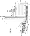
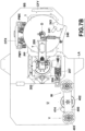
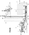
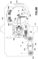
- Figures 4A-11B schematically illustrate the steps of picking up a reel and positioning it on a support (403) of the unwinding station (U).
- the lifting and lowering strokes of the arm (200), there is of the device (D), are each divided into two phases carried out by the sequential movement of the carriages (201) and (204).
- the removal of the reels (1) from the stack (2) involves the vertical movement of each reel parallel to itself, in a horizontal position, that is, along a direction coinciding with the axis of the reel subjected to withdrawal.
- the reels picking and handling cycle performed by the device (D) can be activated when the diameter of a reel (1) present on a support (403) of a carousel (G) in the respective position "Y" reaches a first value of preset control (1) present on a support (403) of a carousel (G) in the respective position "W".
- the arm (500) When a reel (1) taken from the stack (2) is delivered to the respective support (403) placed in the "W" position, the arm (500) is brought closer to the carousel (G) by rotating the arm itself around its axis (V5).
- the operating speed of the corresponding tube-forming machine is reduced so that the step of joining the strips is performed at a reduced speed but without interrupting the feeding of the tube-forming machine.
- the roller connection clutch (508) is activated and the gear motor (509) is activated so that the roller (508) is rotated about its respective axis (A8).
- the control unit (CU) activates the actuator (522) which rotates the arm (518) so as to bring the photocell (519) closer to the reel.
- the photocell (519) is used to detect the passage of the double-sided adhesive (BA) arranged on the external side of the reel delivered to the support (403) in the "W" position while the reel itself is rotated by the roller (508) around the respective pin. (404). Since the aforementioned rotation of the arm (500) determines the approach of the strip (SY) coming from the reel (1Y) to the reel (1W), to make the junction of the strip (SY) to the latter reel (junction necessary to ensure the continuity of the tube feed) it is sufficient to extract the pressure roller (505) by activating the respective actuator (507). Consequently, the strip (SY) of the reel (1Y) in the exhaustion phase sticks to the lateral surface of the reel (1W).
- BA double-sided adhesive
- the blade (510) is extracted to cut the strip (SY) of the reel (1Y) and the double-sided adhesive (BA) remains attached to the tail of the strip (SY) cut.
- the surface (516) is lowered.
- the roller (508) is disconnected from the gearmotor (509) which in turn is deactivated, so that the roller (508) is again free to rotate idly around its own axis (A8) and normal speed operating of the tube-forming machine which is therefore fed with the strip (SW) coming from the reel (1W) is restored, while the arm (500) is returned to its starting position.
- the control unit (CU) activates the actuator (502) which determines the rotation of the carousel (G) around the axis (AU).
- the control unit (CU) commands the said rotation of the carousel (G) by receiving a control signal emitted by a photocell (527) placed on the arm (500) which detects the diameter of the reel (1W).
- a photocell placed on the arm (500) which detects the diameter of the reel (1W).
- the reel (1W) continues to feed the tube-forming machine which uses the strip (SW) coming from the same reel.
- the rotation of the carousel (G) involves the passage of the same carousel near the motorized wheel (413) which in this phase is set in rotation: when the carousel (G) is in this position, the contact between the wheel (413) and the support (403) coming from the "Y” position determines the rotation of the support itself, in particular due to the contact between the wheel (413) and the disk (D40) of the support itself.
- This rotation of the support (403) implies the winding of the tail (TY) of the cut strip of the reel (1Y) on the reel itself. Then, the pin (404) of the support (403) which occupied the "Y” position is lowered so that the reel (1Y) is no longer bound to the carousel.
- the reel (1Y) no longer bound to the carousel (G) is intercepted by the plate (526) and therefore falls into an underlying container (RC) from which it can then be recovered for recycling.
- the arm (500) is temporarily brought towards the carousel (G), so that the strip of material unwinding from the reel (1Y) comes into contact with the surface (513), and the surface (516) is raised with the roller (517). Thereafter, the arm (500) is returned to its initial position spaced from the carousel so that.
- the path of the web that takes place from the reel directed towards the "Y" position is such as not to interfere with the positioning of another reel on the other support of the carousel.
- the rotation of the carousel continues until the support that previously occupied the "Y" position reaches the "W” position to be ready to receive another reel.
- the positions (Y, W) of the supports (403) are swapped, so that in the "W" position a empty support, ie ready to receive a new reel taken from the stack (2), while in the "Y” position there is another support with a reel that continues to feed the tube-forming machine.
- the described sequence is represented in Figs 15A-15L .
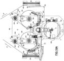
- an arrangement is preferably made comprising a right carousel and a left carousel with respect to the device for picking up the reels from the stack arranged on the platform (PP) as represented in Figs 16A-16N .
- the two rides are independently controlled.
- the carousel on the left works and is controlled as described above with reference to the example shown in Figs. 15A- 15N.
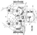
- the right carousel works in the same way but in a phase of the transfer of the empty support (403) towards the "W" position ( Fig.16M ) a vertical axis roller (421) intervenes which widens the trajectory of the web that unwinds from the reel present on the other support.
- the roller (421) is a roller with a vertical axis mounted idle on a respective pin mounted on an arm (422) enslaved to an electric actuator (423) which determines its positioning in active position ( Fig.16M ) and respectively in inactive position ( Figs 16A-16L ).
- the arrows "1T" and “2T” indicate the direction of the webs that take place from the reels supported by the two rides and which are each intended to feed a corresponding tube mill.
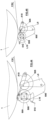
- the supports for the reels in the unwinding station are formed on vertical carousels, that is, carousels with a horizontal rotation axis.
- the orientation of the arm (500) is also modified, which is configured to rotate around a horizontal axis.
- the device (D) for picking up and moving the reels (1) is configured to force the reels themselves to rotate by 90° to change their orientation from horizontal to vertical after they have been withdrawn from the stack (2) and to guide the descent towards the respective vertical rides.
- the aforesaid arm (200) is rotatably mounted on the carriage (201) by means of a horizontal shaft interlocked with a rotary actuator (220). In the example shown in Figs.
- the device (D) is equipped with the suction cup (300) to engage the reels (1).
- the reels (1) When taken from the stack (2), the reels (1) are in a horizontal position, as in the example described above. After its picking up from the stack (2), each reel is rotated by 90°, by means of the rotation of the arm (200) controlled by the actuator (220), whereby the orientation of the reel passes from horizontal to vertical. Said change in orientation of the reel (1) can be performed both when the reel (1) engaged by the device (D) is above the stack (2), that is, it is still in the station (P), and when the reel (1) engaged by the device (D) is located in the unwinding station (U) following the aforementioned rotation of the platform (206) controlled by the actuator (207).
- the device (D) When the reel (1) is above the carousel (G) that is to receive it, the device (D) is lowered towards the carousel itself in order to arrange the reel at a height useful for its placement on the carousel, the latter being positioned in a suitable position to receive the reel.
- the beam (400) of the carousel (G) is mounted on a corresponding support (600) so that it can rotate around its central axis which is horizontal.
- the rotation of the beam (400) is controlled by the gearmotor (MR4).
- the supports for the reels can be arranged in a position (W) for the initial loading and unwinding of the reels and a position (Y) for unwinding and exhausting the reels.
- the supports for the reels consist of pins (404), each of which can be arranged in the extracted position and respectively in the retracted position by means of an actuator (not visible in the drawings) placed on a rear face of the beam (400).
- a movable support (500) is provided on which the means for junction the reels are mounted, the movable support (500) being configured and controlled to approach the reel loading position (W) and move away from this position respectively and being activated when the mobile support is approached to the position (W) for loading the reels.
- the mobile support (500) in this case rotates around a horizontal axis (A5) by means of a pneumatic actuator (A50) constrained on one side to a support (A51) which also supports the arm (500) and, on the opposite side, to a rear part of the same arm.
- the arm (500) is also equipped with a pressure roller (505) arranged in an intermediate position between the rotation axis (A5) and a free end of the arm.
- the pressure roller (505) is mounted idle on a lever (L5) controlled by a pneumatic actuator (A52) and pivoted with a horizontal axis on the arm (500) in such a way that the pressure roller (505) can be arranged in extracted position with respect to an internal side of the arm (500) and respectively in the retracted position depending on the activation or deactivation of the actuator (A52).
- the rotation axis of the pressure roller (505) is parallel to the axis (A5) of rotation of the arm (500).
- the drive roller (508) controlled by the respective gearmotor (509) is mounted on the free end of the arm (500).
- the gearmotor (509) is activated to control the rotation of the drive roller (508) in the reels exchange step as further described below.
- the axis of rotation of the drive roller (508) is parallel to the axis (A5) of rotation of the arm (500).
- the blade (510) is also mounted on the free end of the arm (500).
- the latter is arranged on a lever (L10) pivoted with a horizontal axis on the arm (500) and controlled by a corresponding pneumatic actuator (A10) on the opposite side of the blade (10) with respect to the rotation axis of the lever (L10).
- the rotation axis of the lever (L10) is parallel to the axis (A5) of rotation of the arm (500).
- Figures 35-41 illustrate a sequence of operating steps that can be carried out by means of a system configured in this way. In Fig.
- a reel (1) present in an unwinding position supplies a respective tube mill with the cardboard strip (CS 1) while it is supported by the beam (400) through the corresponding pin (404), the arm (500) is spaced from the carousel (G) and the device for picking up and moving the reels has already picked up a reel (1) from the stack (2) placing it in the station (U) rotated by 90 °.
- the device for picking up and moving the reels has placed the reel (1) in correspondence with the other pin (404) of the carousel (G) which is subsequently extracted for the final delivery of the reel to the carousel.
- the drive roller (508) also acts as a presser to determine the junction of the cardboard strips of the two reels by means of double-sided adhesive similarly to what is described in reference to the previous example.
- the passage of the double-sided adhesive applied to the external side of the new reel is detected by a photocell (FB) placed on a relative mobile support (not visible in the drawings) which allows the same photocell to be placed in a position in which it, when not used, does not interfere with the handling of the elements described.
- FB photocell
- the blade (410) has been placed in the cutting position of the cardboard strip supplied by the reel in the exhaustion phase.
- the new reel supplies the cardboard strip (CS2) to the respective tube mill while the exhausted reel is on the respective pin (404).
- the unwinding unit (UU) comprises several supports (in this example the pins 404) mounted on a structure (G) controlled and moved to arrange cyclically said supports in correspondence with several positions which include a predetermined position (W) for loading the reels and a different predetermined position (Y) for exhaustion of the reels.
- the position (Y) of exhaustion of the reels is also an intermediate unwinding position, ie a position in which the reels are unwound until they are exhausted.
- the reels loading position is not also an initial unwinding position.
- a position (Z) for automatic unloading of the exhausted reels is formed between the exhaustion position and the loading position.
- the continuous cycle achievable by means of a system in accordance with the present invention contemplates the use of automatic loading means to create a fully automatic cycle of loading the unwinding station and continuous feeding of the tube mills.
- the junction of the webs coming respectively from the reels in the depletion phase with the webs coming from the new reels arranged in the loading position are means configured to perform the aforementioned junction without interrupting the power supply of the tube mills, that is, means configured to perform the "on the fly" junction of the webs while the le reels involved rotate around their respective axes.
- said junction means are mounted on a mobile support (in the example described above, the arm 500) configured and controlled to approach said support structure of the reels in the unwinding station and respectively move away from said structure.
- the junction means are activated when the said mobile support is approached to the said support structure of the reels in the unwinding station, so that the junction of the said webs takes place in correspondence with the loading position of the new reels, or in correspondence with a different position from the position of exhaustion of the reels.
- the said junction means comprise a pressure roller adapted to exert a pressure on the parts to be joined when the passage of a portion of adhesive material arranged on the new reel is detected, this detection being performed by detection means mounted on the said movable support.
- the adhesive material is a double-sided web strip.
- the step of loading the reels by the automatic loading means is preceded by a step of preparing a stack of reels on a mobile platform whose position with respect to the automatic loading means is controlled and possibly modified in a horizontal plane (x, y) by means for detecting an initial position of the platform and, preferably, also by means for detecting the instantaneous position of the automatic loading means with respect to the position of the stack arranged on said platform.
- the position of the platform in the said plane (x, y) is controlled by detecting the position of a central axis (AC) of the said stack of reels with respect to an axis (A9) of the automatic loading means.
- said platform is connected to two electric actuators (PMX, PMY) configured and controlled to move the platform along two mutually orthogonal directions of said plane (x, y).
- the automatic means for loading the reels are preferably configured to provide an integrated unit comprising pneumatic means intended to pressurize a space (S) inside the stack of reels, in which said space includes the interface between a reel higher than the stack and the reel below, and mechanical or pneumatic gripping means configured and controlled to respectively grip and release the highest reel in the stack.
- pneumatic means intended to pressurize a space (S) inside the stack of reels, in which said space includes the interface between a reel higher than the stack and the reel below, and mechanical or pneumatic gripping means configured and controlled to respectively grip and release the highest reel in the stack.
- said integrated unit is a unit attached to an arm (200) movable along a predetermined path comprised between the station for depositing the stack of reels on said platform and the station for unwinding the reels.
- the automatic means for loading the reels can be configured and controlled to perform the withdrawal of the reels from the stack arranged on the platform, their movement along the said path, and the positioning of the reels in the unwinding station, always keeping the reels in horizontal order, that is with the central axis of the reels always oriented vertically.
- the automatic means for loading the reels can be configured and controlled to perform the withdrawal of the reels from the stack arranged on the platform, their movement along the said path, and the positioning of the reels in the unwinding station, keeping the reels in a horizontal position, that is, with the central axis of the reels oriented vertically along an initial part of said path and to rotate the orientation of the reels by 90° at the end of said initial part of the path.
- the orientation of the reels themselves is maintained in the initial phase of picking up the reels from the stack.
- the orientation of the reels presented at the time of positioning the stack in the reel picking station (P) is preferably maintained.
- the automatic means for loading the reels can be provided with an additional device for reversible coupling of the reels to the same automatic loading means to prevent any detachment of the reels in the event of malfunctioning of the mechanical or pneumatic gripping means.
- said path can be configured to comprise a first vertical stroke for lifting the reels, a second horizontal stroke along a circular arc and a third vertical stroke for descending the reels.
- At least one carousel structure (G) is arranged in the reel unwinding station on which several supports (403) are mounted, each suitable for supporting a corresponding reel and which is controlled and moved to cyclically arranging said supports in correspondence with several operating positions which include at least one predetermined loading position and at least one different predetermined exhaustion position, and in which preferably the loading position is also an initial unwinding position and the exhaustion position is also an intermediate unwinding position.
- the carousels (G) can be two in number, intended to feed two distinct tube mills. In the event that the system is intended to power only one tube mill, only one carousel can be provided (G). More generally, the number of carousels (G), or the number of unwinding units (UU), is equal to the number of cardboard strips used by the tube mills served by the plant.
- each carousel (G) comprises two supports (403) in diametrically opposite positions with respect to a central axis of rotation of the carousel.
- the carousel (G) can be a carousel with a vertical axis or also a carousel with a horizontal axis.
Landscapes
- Replacement Of Web Rolls (AREA)
- Machines For Manufacturing Corrugated Board In Mechanical Paper-Making Processes (AREA)
- Paper (AREA)
Claims (22)
- Anlage zur Handhabung von Kartonrollen zur Beschickung von Rohrformmaschinen, umfassend eine Rollenaufnahmestation (P), die dazu konfiguriert ist, einen Stapel (2) übereinanderliegender Kartonrollen (1) zu empfangen, eine Station (U) zum Abwickeln der Rollen (1), die mindestens eine Abwickeleinheit (UU) umfasst, die dazu angepasst ist, die abzuwickelnden Rollen in einer Position zu stützen, die ihr Abwickeln begünstigt, wobei in der Abwickelstation (U) außerdem Spleißmittel bereitgestellt sind, die dazu konfiguriert sind, einen abschließenden Abschnitt (TY) einer sich aufbrauchenden Rolle (1 Y) mit einer neuen Rolle (1W) zu spleißen, um die in der Abwickelstation (U) nacheinander angeordneten Rollen kontinuierlich abzuwickeln, und Handhabungsmittel (D) zum Bewegen der Rollen (1) entlang eines Pfades, der zwischen der Rollenaufnahmestation (P) und der Abwickelstation (U) umfasst ist, wobeisie eine programmierbare Steuereinheit (CU) umfassen, die dazu konfiguriert und programmiert ist, die Rollenaufnahmemittel, die mindestens eine Abwickeleinheit und die Spleißmittel gemäß einem kontinuierlichen Zyklus zu steuern, wobei, während eine Rolle auf einer relativen Stütze der mindestens einen Abwickeleinheit abgewickelt wird, eine andere Rolle auf einer anderen Stütze der gleichen Abwickeleinheit positioniert wird und die Stützen zyklisch durch jeweilige mechanische Bewegungsmittel bewegt werden, um mindestens eine vorbestimmte Ladeposition (W) und mindestens eine unterschiedliche vorbestimmte Erschöpfungsposition (Y) einzunehmen, und wobei die Spleißmittel zyklisch die Spleißung eines Endabschnitts einer Rolle in der Aufbrauchphase mit einem Anfangsabschnitt einer anderen Rolle durchführen, die in der Ladeposition angeordnet ist, und dadurch gekennzeichnet,dass die Mittel (D) zur Handhabung der Rollen pneumatische Mittel umfassen, die dazu angepasst sind, einen Raum (S) innerhalb des Rollenstapels unter Druck zu setzen, bei dem der Raum die Schnittstelle zwischen einer obersten Rolle des Stapels und der darunterliegenden Rolle sowie mechanische oder pneumatische Greifmittel beinhaltet, die zum Greifen bzw. Freigeben der obersten Rolle des Stapels konfiguriert sind und gesteuert werden.
- Anlage gemäß Anspruch 1, dadurch gekennzeichnet, dass die mindestens eine Abwickeleinheit (UU) eine Vielzahl von Stützen (403; 404) umfasst, die auf einer Struktur (G) montiert sind, die gesteuert und bewegt wird, um die Stützen zyklisch in Übereinstimmung mit einer Vielzahl von Betriebspositionen anzuordnen, die eine vorbestimmte Position (W) zum Laden der Rollen und eine unterschiedlichevorbestimmte Position (Y) zum Erschöpfen der Rollen beinhaltet, und dadurch, dass die Rollenaufnahmestation (P) dazu konfiguriert ist, einen Stapel (2) übereinanderliegender Kartonrollen (1) zu empfangen, und dadurch, dass die Mittel (D) zur Handhabung der Rollen dazu konfiguriert sind und gesteuert werden, jeweils eine Rolle gleichzeitig von dem Stapel (2) aufzunehmen und diese Rolle von der Aufnahmestation (P) zu einer Stütze (403; 404) der mindestens einen Abwickeleinheit (UU) zu bewegen, die in der Ladeposition (W) angeordnet ist.
- Anlage gemäß Anspruch 1, dadurch gekennzeichnet, dass die Rollenladeposition (W) außerdem eine Anfangsabwickelposition ist, in der mit dem Abwickeln der Rollen begonnen wird, und/oder dass die Rollenerschöpfungsposition (Y) außerdem eine Zwischenabwickelposition ist, in der die Rollen abgewickelt werden, bis sie aufgebraucht sind.
- Anlage gemäß Anspruch 1, dadurch gekennzeichnet, dass zwischen der Erschöpfungsposition (Y) und Ladeposition (W) eine unterschiedliche Position (Z) zum Entladen der erschöpften Rollen bereitgestellt ist.
- Anlage gemäß Anspruch 2, dadurch gekennzeichnet, dass die Struktur (G) eine Karussellstruktur ist.
- Anlage gemäß Anspruch 5, dadurch gekennzeichnet, dass die Karussellstruktur ein Karussell mit einer vertikalen Achse ist.
- Anlage gemäß Anspruch 5, dadurch gekennzeichnet, dass die Karussellstruktur ein Karussell mit horizontaler Achse ist.
- Anlage gemäß Anspruch 5-7, dadurch gekennzeichnet, dass jedes Karussell (G) zwei Stützen (403; 404) in diametral gegenüberliegenden Positionen in Bezug auf eine zentrale Drehachse (AU) des Karussells umfasst.
- Anlage gemäß Anspruch 1 und 2, dadurch gekennzeichnet, dass die Spleißmittel auf einer beweglichen Stütze (500) montiert sind, die dazu konfiguriert ist und gesteuert wird, sich der Struktur (G) zu nähern bzw. sich von der Struktur zu entfernen, und die aktiviert wird, wenn sich die bewegliche Stütze der Struktur (G) nähert.
- Anlage gemäß Anspruch 9, dadurch gekennzeichnet, dass die bewegliche Stütze (500) eine Stütze ist, die drehbar auf einer entsprechenden Drehachse (V5; A5) montiert ist.
- Anlage gemäß Anspruch 9, dadurch gekennzeichnet, dass die Spleißmittel eine Druckrolle (505) umfassen, die auf der beweglichen Stütze (500) montiert und dazu angepasst ist, einen Druck auf die zu spleißenden Teile auszuüben, wenn der Durchgang eines Abschnitts von Klebematerial (BA) erkannt wird, das auf der neuen Rolle angeordnet ist, wobei die Erkennung durch Erkennungsmittel (519) durchgeführt wird, die dazu konfiguriert sind, den Durchgang des Abschnitts von Klebematerial (BA) zu erkennen.
- Anlage gemäß Anspruch 9, dadurch gekennzeichnet, dass sie eine Klinge (510) umfasst, die auf der beweglichen Stütze (500) montiert ist und dazu konfiguriert ist und gesteuert wird, den Kartonstreifen (SY) zu schneiden, der sich in der Erschöpfungsphase von den Rollen abwickelt, wobei die Klinge gemäß einer Erkennung aktiviert wird, die durch Erkennungsmittel (519) durchgeführt wird, die dazu konfiguriert sind, den Durchgang eines Abschnitts von Klebematerial (BA) zu erkennen, das auf der neuen Rolle angeordnet ist.
- Anlage gemäß Anspruch 1, dadurch gekennzeichnet, dass sich in der Rollenaufnahmestation (P) eine bewegliche Plattform (PP) befindet, deren Position in Bezug auf die Lademittel (D) auf einer horizontalen Ebene (x, y) durch Erkennen der Position einer zentralen Achse (AC) des Rollenstapels in Bezug auf eine Achse (A9) der Lademittel gesteuert wird, wobei die Plattform (PP) dazu konfiguriert ist, den Stapel (2) aus übereinanderliegenden Kartonrollen (1) während der Positionierung des Stapels (2) in der Rollenaufnahmestation (P) zu empfangen.
- Anlage gemäß Anspruch 13, dadurch gekennzeichnet, dass die Plattform (PP) mit zwei elektrischen Aktoren (PMX, PMY) verbunden ist, die dazu konfiguriert sind und gesteuert werden, die Plattform entlang zweier zueinander orthogonaler Richtungen der Ebene (x, y) zu bewegen.
- Anlage gemäß Anspruch 1, dadurch gekennzeichnet, dass die Mittel (D) zur Handhabung der Rollen mit einem Arm (200) verbunden sind, der entlang des Pfades bewegt werden kann.
- Anlage gemäß Anspruch 1, dadurch gekennzeichnet, dass die Rollenhandhabungsmittel dazu konfiguriert sind und gesteuert werden, die Rollen von dem Stapel in der Rollenaufnahmestation (P) aufzunehmen, die Rollen entlang des Pfads zu bewegen und die Rollen in der Abwickelstation zu positionieren, indem sie die Rollen mindestens bei dem Schritt des Aufnehmens der Rollen von dem Stapel (2) in einer horizontalen Position halten.
- Anlage gemäß Anspruch 1, dadurch gekennzeichnet, dass die Mittel (D) zur Handhabung der Rollen mit einer Sicherheitsvorrichtung bereitgestellt sind, welche die Rollen hält, während die Rollen durch die Mittel (D) zur Handhabung der Rollen bewegt werden.
- Anlage gemäß Anspruch 1, dadurch gekennzeichnet, dass der Pfad einen ersten vertikalen Lauf zum Anheben der Rollen, einen zweiten horizontalen Lauf, der entlang eines Kreisbogens verläuft, und einen dritten vertikalen Abstiegslauf für die Rollen umfasst.
- Verfahren zur Handhabung von Kartonrollen zur Beschickung von Rohrformmaschinen, umfassend die Anordnung einer Rollenaufnahmestation (P), die dazu konfiguriert ist, einen Stapel übereinanderliegender Kartonrollen (1) zu empfangen, eine Station (U) zum Abwickeln der Rollen (1), die mindestens eine Abwickeleinheit (UU) umfasst, die zum Stützen der abzuwickelnden Rollen in einer Position angepasst ist, die ihr Abwickeln begünstigt, wobei außerdem Spleißmittel in der Abwickelstation (U) bereitgestellt sind, die dazu konfiguriert sind, einen abschließenden Abschnitt (TY) einer Rolle (1 Y) in der Aufbrauchphase mit einer neuen Rolle (1W) zu spleißen, um die in der Abwickelstation (U) nacheinander angeordneten Rollen kontinuierlich abzuwickeln, und Handhabungsmittel (D) zum Bewegen der Rollen (1) entlang eines vorbestimmten Pfades zwischen der Rollenaufnahmestation (P) und der Abwickelstation (U), wobeidie Mittel zum Aufnehmen der Rollen, die mindestens eine Abwickelstation und die Spleißmittel gesteuert werden, um einen kontinuierlichen Zyklus auszuführen, wobei, während eine Rolle auf einer relativen Stütze der mindestens einen Abwickeleinheit abgewickelt wird, eine andere Rolle auf einer anderen Stütze der gleichen Abwickeleinheit positioniert wird und die Stützen zyklisch durch jeweilige mechanische Bewegungsmittel bewegt werden, um mindestens eine vorbestimmte Ladeposition (W) und mindestens eine unterschiedliche vorbestimmte Erschöpfungsposition (Y) einzunehmen, und wobei die Spleißmittel zyklisch die Spleißung eines Endabschnitts einer Rolle in der Aufbrauchphase mit einem Anfangsabschnitt einer anderen Rolle durchführen, die in der Ladeposition angeordnet ist, und dadurch gekennzeichnet,dass die Mittel (D) zur Handhabung der Rollen pneumatische Mittel umfassen, die dazu angepasst sind, einen Raum (S) innerhalb des Rollenstapels unter Druck zu setzen, bei dem der Raum die Schnittstelle zwischen einer obersten Rolle des Stapels und der darunterliegenden Rolle sowie mechanische oder pneumatische Greifmittel beinhaltet, die zum Greifen bzw. Freigeben der obersten Rolle des Stapels konfiguriert sind und gesteuert werden.
- Verfahren gemäß Anspruch 19, dadurch gekennzeichnet, dass die mindestens eine Abwickeleinheit (UU) eine Vielzahl von Stützen (403; 404) umfasst, die auf einer Struktur (G) montiert sind, die gesteuert und bewegt wird, um die Stützen zyklisch in Übereinstimmung mit einer Vielzahl von Betriebspositionen anzuordnen, die eine vorbestimmte Position (W) zum Laden der Rollen und eine unterschiedliche vorbestimmte Position (Y) zum Erschöpfen der Rollen beinhaltet, dadurch, dass die Rollenaufnahmestation (P) dazu konfiguriert ist, einen Stapel (2) übereinanderliegender Kartonrollen (1) zu empfangen, und dadurch, dass die Mittel (D) zur Handhabung der Rollen dazu konfiguriert sind und gesteuert werden, jeweils eine Rolle gleichzeitig von dem Stapel (2) aufzunehmen und diese Rolle von der Aufnahmestation (P) zu einer Stütze (403; 404) der mindestens einen Abwickeleinheit (UU) zu bewegen, die in der Ladeposition (W) angeordnet ist.
- Verfahren gemäß Anspruch 19, dadurch gekennzeichnet, dass die Rollenladeposition (W) außerdem eine Anfangsabwickelposition ist, in der mit dem Abwickeln der Rollen begonnen wird, und/oder dass die Rollenerschöpfungsposition (Y) außerdem eine Zwischenabwickelposition ist, in der die Rollen abgewickelt werden, bis sie aufgebraucht sind.
- Verfahren gemäß Anspruch 19, dadurch gekennzeichnet, dass zwischen der Erschöpfungsposition (Y) und der Ladeposition (W) eine unterschiedliche Position (Z) zum Entladen der erschöpften Rollen bereitgestellt ist.
Priority Applications (1)
| Application Number | Priority Date | Filing Date | Title |
|---|---|---|---|
| RS20240972A RS65957B1 (sr) | 2020-12-14 | 2021-12-09 | Postrojenje i postupak za rukovanje kartonskim koturima |
Applications Claiming Priority (2)
| Application Number | Priority Date | Filing Date | Title |
|---|---|---|---|
| IT102020000030662A IT202000030662A1 (it) | 2020-12-14 | 2020-12-14 | Impianto e processo per la movimentazione di bobine di cartone. |
| PCT/IT2021/050397 WO2022130427A1 (en) | 2020-12-14 | 2021-12-09 | Plant and process for handling cardboard reels |
Publications (2)
| Publication Number | Publication Date |
|---|---|
| EP4259564A1 EP4259564A1 (de) | 2023-10-18 |
| EP4259564B1 true EP4259564B1 (de) | 2024-08-07 |
Family
ID=74759363
Family Applications (1)
| Application Number | Title | Priority Date | Filing Date |
|---|---|---|---|
| EP21848041.6A Active EP4259564B1 (de) | 2020-12-14 | 2021-12-09 | Anlage und verfahren zur handhabung von kartonrollen |
Country Status (9)
| Country | Link |
|---|---|
| US (1) | US12421068B2 (de) |
| EP (1) | EP4259564B1 (de) |
| CN (1) | CN116685546A (de) |
| ES (1) | ES2988260T3 (de) |
| FI (1) | FI4259564T3 (de) |
| IT (1) | IT202000030662A1 (de) |
| PL (1) | PL4259564T3 (de) |
| RS (1) | RS65957B1 (de) |
| WO (1) | WO2022130427A1 (de) |
Families Citing this family (2)
| Publication number | Priority date | Publication date | Assignee | Title |
|---|---|---|---|---|
| DE102020118417A1 (de) * | 2020-07-13 | 2022-01-13 | Wöhr Autoparksysteme GmbH | Parkanlage für Kraftfahrzeuge |
| CN118387674B (zh) * | 2024-07-01 | 2024-09-20 | 山东康桥实业有限公司 | 一种胶带薄膜加工用全自动整平切割设备 |
Citations (1)
| Publication number | Priority date | Publication date | Assignee | Title |
|---|---|---|---|---|
| IT202000030644A1 (it) * | 2020-12-14 | 2022-06-14 | Futura Spa | Dispositivo e metodo per la manipolazione di bobine di cartone. |
Family Cites Families (12)
| Publication number | Priority date | Publication date | Assignee | Title |
|---|---|---|---|---|
| DE3000723C2 (de) * | 1980-01-08 | 1985-09-26 | B.A.T. Cigaretten-Fabriken Gmbh, 2000 Hamburg | Verfahren und Vorrichtung zum kontinuierlichen Zuführen von Papierbobinen zu einer Maschine der tabakverarbeitenden Industrie |
| DE3534771C2 (de) * | 1984-11-16 | 1995-09-21 | Hauni Werke Koerber & Co Kg | Bobinenwechseleinheit für Maschinen der tabakverarbeitenden Industrie |
| IT1273218B (it) * | 1994-01-20 | 1997-07-07 | Gd Spa | Dispositivo di alimentazione di bobine ad una macchina utilizzatrice |
| ITFI20030118A1 (it) | 2003-04-28 | 2004-10-29 | Fabio Perini | Dispositivo e metodo per provocare lo strappo di nastri cartacei in macchine ribobinatrici |
| DE102005060638A1 (de) * | 2005-12-13 | 2007-06-14 | Hauni Maschinenbau Ag | Vorrichtung und Verfahren zum Handhaben von Bobinen innerhalb einer Automatisierungszelle sowie Automatisierungszelle |
| RS57069B1 (sr) | 2014-01-29 | 2018-06-29 | Futura Spa | Oprema i postupak za proizvodnju kartonskih cevi |
| US9670021B2 (en) * | 2014-08-28 | 2017-06-06 | The Procter & Gamble Company | Mandrel |
| US9926160B2 (en) * | 2014-08-28 | 2018-03-27 | The Procter & Gamble Company | Robotic unwind stand |
| US9919887B2 (en) * | 2014-08-28 | 2018-03-20 | The Procter & Gamble Company | Web material unwind stand |
| EP3212391B1 (de) | 2014-10-29 | 2018-10-17 | Futura S.p.A. | Maschine zur herstellung von pappröhren |
| US20170101281A1 (en) * | 2015-10-13 | 2017-04-13 | Curt G. Joa, Inc. | Disposable product assembly systems and methods |
| DE102017206549A1 (de) * | 2017-04-19 | 2018-10-25 | Robert Bosch Gmbh | Verbrauchsmaterialhandhabungsvorrichtung zu einem Transport und/oder zu einer Handhabung von zumindest einem Verbrauchsmaterial, insbesondere eines Verpackungsmaterials |
-
2020
- 2020-12-14 IT IT102020000030662A patent/IT202000030662A1/it unknown
-
2021
- 2021-12-09 US US18/038,485 patent/US12421068B2/en active Active
- 2021-12-09 PL PL21848041.6T patent/PL4259564T3/pl unknown
- 2021-12-09 ES ES21848041T patent/ES2988260T3/es active Active
- 2021-12-09 CN CN202180083820.XA patent/CN116685546A/zh active Pending
- 2021-12-09 FI FIEP21848041.6T patent/FI4259564T3/fi active
- 2021-12-09 RS RS20240972A patent/RS65957B1/sr unknown
- 2021-12-09 EP EP21848041.6A patent/EP4259564B1/de active Active
- 2021-12-09 WO PCT/IT2021/050397 patent/WO2022130427A1/en not_active Ceased
Patent Citations (1)
| Publication number | Priority date | Publication date | Assignee | Title |
|---|---|---|---|---|
| IT202000030644A1 (it) * | 2020-12-14 | 2022-06-14 | Futura Spa | Dispositivo e metodo per la manipolazione di bobine di cartone. |
Also Published As
| Publication number | Publication date |
|---|---|
| FI4259564T3 (fi) | 2024-09-03 |
| PL4259564T3 (pl) | 2025-02-03 |
| RS65957B1 (sr) | 2024-10-31 |
| US20240101382A1 (en) | 2024-03-28 |
| JP2023554344A (ja) | 2023-12-27 |
| WO2022130427A1 (en) | 2022-06-23 |
| US12421068B2 (en) | 2025-09-23 |
| ES2988260T3 (es) | 2024-11-19 |
| EP4259564A1 (de) | 2023-10-18 |
| IT202000030662A1 (it) | 2022-06-14 |
| CN116685546A (zh) | 2023-09-01 |
Similar Documents
| Publication | Publication Date | Title |
|---|---|---|
| US4948060A (en) | Automatic web roll handling system for splicing | |
| EP4259564B1 (de) | Anlage und verfahren zur handhabung von kartonrollen | |
| EP1306332B1 (de) | Automatischer Umwickler insbesondere für flexible Folie aus Plastikmaterial und dazugehöriges Verfahren für die Produktion von Rollen | |
| EP4259565B1 (de) | Anlage und verfahren zur bewegung von kartonkernen | |
| EP1689660B1 (de) | Anlage zur handhabung von rollen von papier oder dergleichen und zu deren umwandlung | |
| CN112478256A (zh) | 一种卷筒纸拉膜包装线 | |
| EP4259563B1 (de) | Anlage und verfahren zur handhabung von kartonrollen | |
| US11254534B2 (en) | Unwinder for reels and unwinding method | |
| US20230416017A1 (en) | Device and process for handling cardboard reels | |
| EP3609826B1 (de) | Vorrichtung zum entfernen von papier aus grossrollen zur herstellung von rollen aus papiermaterial | |
| JP7785775B2 (ja) | ボール紙リールを取り扱うための装置及び方法 | |
| JP3453350B2 (ja) | 連続巻出装置及びウェブの連続巻出方法 | |
| CZ383697A3 (cs) | Navíjecí zařízení pásového materiálu | |
| EP2511209B1 (de) | Anordnung zur Handhabung von Machinenrollen und Aufrollwellen im Zusammenhang mit der Herstellung von Faserbahnen | |
| CN113573998B (zh) | 用于替换退绕机中的卷筒的装置以及相关方法 | |
| CN119630600A (zh) | 用于生产由幅材类材料制成的管的生产线 |
Legal Events
| Date | Code | Title | Description |
|---|---|---|---|
| STAA | Information on the status of an ep patent application or granted ep patent |
Free format text: STATUS: UNKNOWN |
|
| STAA | Information on the status of an ep patent application or granted ep patent |
Free format text: STATUS: THE INTERNATIONAL PUBLICATION HAS BEEN MADE |
|
| PUAI | Public reference made under article 153(3) epc to a published international application that has entered the european phase |
Free format text: ORIGINAL CODE: 0009012 |
|
| STAA | Information on the status of an ep patent application or granted ep patent |
Free format text: STATUS: REQUEST FOR EXAMINATION WAS MADE |
|
| 17P | Request for examination filed |
Effective date: 20230518 |
|
| AK | Designated contracting states |
Kind code of ref document: A1 Designated state(s): AL AT BE BG CH CY CZ DE DK EE ES FI FR GB GR HR HU IE IS IT LI LT LU LV MC MK MT NL NO PL PT RO RS SE SI SK SM TR |
|
| DAV | Request for validation of the european patent (deleted) | ||
| DAX | Request for extension of the european patent (deleted) | ||
| GRAP | Despatch of communication of intention to grant a patent |
Free format text: ORIGINAL CODE: EPIDOSNIGR1 |
|
| STAA | Information on the status of an ep patent application or granted ep patent |
Free format text: STATUS: GRANT OF PATENT IS INTENDED |
|
| INTG | Intention to grant announced |
Effective date: 20240510 |
|
| GRAS | Grant fee paid |
Free format text: ORIGINAL CODE: EPIDOSNIGR3 |
|
| GRAA | (expected) grant |
Free format text: ORIGINAL CODE: 0009210 |
|
| STAA | Information on the status of an ep patent application or granted ep patent |
Free format text: STATUS: THE PATENT HAS BEEN GRANTED |
|
| AK | Designated contracting states |
Kind code of ref document: B1 Designated state(s): AL AT BE BG CH CY CZ DE DK EE ES FI FR GB GR HR HU IE IS IT LI LT LU LV MC MK MT NL NO PL PT RO RS SE SI SK SM TR |
|
| REG | Reference to a national code |
Ref country code: GB Ref legal event code: FG4D |
|
| REG | Reference to a national code |
Ref country code: CH Ref legal event code: EP |
|
| REG | Reference to a national code |
Ref country code: IE Ref legal event code: FG4D |
|
| REG | Reference to a national code |
Ref country code: DE Ref legal event code: R096 Ref document number: 602021017027 Country of ref document: DE |
|
| REG | Reference to a national code |
Ref country code: FI Ref legal event code: FGE |
|
| REG | Reference to a national code |
Ref country code: SE Ref legal event code: TRGR |
|
| REG | Reference to a national code |
Ref country code: ES Ref legal event code: FG2A Ref document number: 2988260 Country of ref document: ES Kind code of ref document: T3 Effective date: 20241119 |
|
| REG | Reference to a national code |
Ref country code: LT Ref legal event code: MG9D |
|
| REG | Reference to a national code |
Ref country code: NL Ref legal event code: MP Effective date: 20240807 |
|
| PGFP | Annual fee paid to national office [announced via postgrant information from national office to epo] |
Ref country code: DE Payment date: 20241210 Year of fee payment: 4 |
|
| PG25 | Lapsed in a contracting state [announced via postgrant information from national office to epo] |
Ref country code: NO Free format text: LAPSE BECAUSE OF FAILURE TO SUBMIT A TRANSLATION OF THE DESCRIPTION OR TO PAY THE FEE WITHIN THE PRESCRIBED TIME-LIMIT Effective date: 20241107 |
|
| REG | Reference to a national code |
Ref country code: AT Ref legal event code: MK05 Ref document number: 1710725 Country of ref document: AT Kind code of ref document: T Effective date: 20240807 |
|
| PG25 | Lapsed in a contracting state [announced via postgrant information from national office to epo] |
Ref country code: NL Free format text: LAPSE BECAUSE OF FAILURE TO SUBMIT A TRANSLATION OF THE DESCRIPTION OR TO PAY THE FEE WITHIN THE PRESCRIBED TIME-LIMIT Effective date: 20240807 Ref country code: PT Free format text: LAPSE BECAUSE OF FAILURE TO SUBMIT A TRANSLATION OF THE DESCRIPTION OR TO PAY THE FEE WITHIN THE PRESCRIBED TIME-LIMIT Effective date: 20241209 Ref country code: GR Free format text: LAPSE BECAUSE OF FAILURE TO SUBMIT A TRANSLATION OF THE DESCRIPTION OR TO PAY THE FEE WITHIN THE PRESCRIBED TIME-LIMIT Effective date: 20241108 |
|
| PGFP | Annual fee paid to national office [announced via postgrant information from national office to epo] |
Ref country code: FI Payment date: 20241219 Year of fee payment: 4 |
|
| PG25 | Lapsed in a contracting state [announced via postgrant information from national office to epo] |
Ref country code: BG Free format text: LAPSE BECAUSE OF FAILURE TO SUBMIT A TRANSLATION OF THE DESCRIPTION OR TO PAY THE FEE WITHIN THE PRESCRIBED TIME-LIMIT Effective date: 20240807 |
|
| PGFP | Annual fee paid to national office [announced via postgrant information from national office to epo] |
Ref country code: FR Payment date: 20241227 Year of fee payment: 4 |
|
| PG25 | Lapsed in a contracting state [announced via postgrant information from national office to epo] |
Ref country code: LV Free format text: LAPSE BECAUSE OF FAILURE TO SUBMIT A TRANSLATION OF THE DESCRIPTION OR TO PAY THE FEE WITHIN THE PRESCRIBED TIME-LIMIT Effective date: 20240807 |
|
| PG25 | Lapsed in a contracting state [announced via postgrant information from national office to epo] |
Ref country code: AT Free format text: LAPSE BECAUSE OF FAILURE TO SUBMIT A TRANSLATION OF THE DESCRIPTION OR TO PAY THE FEE WITHIN THE PRESCRIBED TIME-LIMIT Effective date: 20240807 Ref country code: IS Free format text: LAPSE BECAUSE OF FAILURE TO SUBMIT A TRANSLATION OF THE DESCRIPTION OR TO PAY THE FEE WITHIN THE PRESCRIBED TIME-LIMIT Effective date: 20241207 |
|
| PG25 | Lapsed in a contracting state [announced via postgrant information from national office to epo] |
Ref country code: HR Free format text: LAPSE BECAUSE OF FAILURE TO SUBMIT A TRANSLATION OF THE DESCRIPTION OR TO PAY THE FEE WITHIN THE PRESCRIBED TIME-LIMIT Effective date: 20240807 |
|
| PGFP | Annual fee paid to national office [announced via postgrant information from national office to epo] |
Ref country code: RO Payment date: 20241204 Year of fee payment: 4 |
|
| PGFP | Annual fee paid to national office [announced via postgrant information from national office to epo] |
Ref country code: RS Payment date: 20241128 Year of fee payment: 4 |
|
| PGFP | Annual fee paid to national office [announced via postgrant information from national office to epo] |
Ref country code: SE Payment date: 20241219 Year of fee payment: 4 |
|
| PG25 | Lapsed in a contracting state [announced via postgrant information from national office to epo] |
Ref country code: PT Free format text: LAPSE BECAUSE OF FAILURE TO SUBMIT A TRANSLATION OF THE DESCRIPTION OR TO PAY THE FEE WITHIN THE PRESCRIBED TIME-LIMIT Effective date: 20241209 Ref country code: NO Free format text: LAPSE BECAUSE OF FAILURE TO SUBMIT A TRANSLATION OF THE DESCRIPTION OR TO PAY THE FEE WITHIN THE PRESCRIBED TIME-LIMIT Effective date: 20241107 Ref country code: NL Free format text: LAPSE BECAUSE OF FAILURE TO SUBMIT A TRANSLATION OF THE DESCRIPTION OR TO PAY THE FEE WITHIN THE PRESCRIBED TIME-LIMIT Effective date: 20240807 Ref country code: LV Free format text: LAPSE BECAUSE OF FAILURE TO SUBMIT A TRANSLATION OF THE DESCRIPTION OR TO PAY THE FEE WITHIN THE PRESCRIBED TIME-LIMIT Effective date: 20240807 Ref country code: IS Free format text: LAPSE BECAUSE OF FAILURE TO SUBMIT A TRANSLATION OF THE DESCRIPTION OR TO PAY THE FEE WITHIN THE PRESCRIBED TIME-LIMIT Effective date: 20241207 Ref country code: HR Free format text: LAPSE BECAUSE OF FAILURE TO SUBMIT A TRANSLATION OF THE DESCRIPTION OR TO PAY THE FEE WITHIN THE PRESCRIBED TIME-LIMIT Effective date: 20240807 Ref country code: GR Free format text: LAPSE BECAUSE OF FAILURE TO SUBMIT A TRANSLATION OF THE DESCRIPTION OR TO PAY THE FEE WITHIN THE PRESCRIBED TIME-LIMIT Effective date: 20241108 Ref country code: BG Free format text: LAPSE BECAUSE OF FAILURE TO SUBMIT A TRANSLATION OF THE DESCRIPTION OR TO PAY THE FEE WITHIN THE PRESCRIBED TIME-LIMIT Effective date: 20240807 Ref country code: AT Free format text: LAPSE BECAUSE OF FAILURE TO SUBMIT A TRANSLATION OF THE DESCRIPTION OR TO PAY THE FEE WITHIN THE PRESCRIBED TIME-LIMIT Effective date: 20240807 |
|
| PGFP | Annual fee paid to national office [announced via postgrant information from national office to epo] |
Ref country code: TR Payment date: 20241202 Year of fee payment: 4 |
|
| PG25 | Lapsed in a contracting state [announced via postgrant information from national office to epo] |
Ref country code: DK Free format text: LAPSE BECAUSE OF FAILURE TO SUBMIT A TRANSLATION OF THE DESCRIPTION OR TO PAY THE FEE WITHIN THE PRESCRIBED TIME-LIMIT Effective date: 20240807 Ref country code: SM Free format text: LAPSE BECAUSE OF FAILURE TO SUBMIT A TRANSLATION OF THE DESCRIPTION OR TO PAY THE FEE WITHIN THE PRESCRIBED TIME-LIMIT Effective date: 20240807 |
|
| PGFP | Annual fee paid to national office [announced via postgrant information from national office to epo] |
Ref country code: ES Payment date: 20250131 Year of fee payment: 4 |
|
| PG25 | Lapsed in a contracting state [announced via postgrant information from national office to epo] |
Ref country code: EE Free format text: LAPSE BECAUSE OF FAILURE TO SUBMIT A TRANSLATION OF THE DESCRIPTION OR TO PAY THE FEE WITHIN THE PRESCRIBED TIME-LIMIT Effective date: 20240807 |
|
| PG25 | Lapsed in a contracting state [announced via postgrant information from national office to epo] |
Ref country code: CZ Free format text: LAPSE BECAUSE OF FAILURE TO SUBMIT A TRANSLATION OF THE DESCRIPTION OR TO PAY THE FEE WITHIN THE PRESCRIBED TIME-LIMIT Effective date: 20240807 |
|
| PGFP | Annual fee paid to national office [announced via postgrant information from national office to epo] |
Ref country code: PL Payment date: 20241120 Year of fee payment: 4 |
|
| PG25 | Lapsed in a contracting state [announced via postgrant information from national office to epo] |
Ref country code: SK Free format text: LAPSE BECAUSE OF FAILURE TO SUBMIT A TRANSLATION OF THE DESCRIPTION OR TO PAY THE FEE WITHIN THE PRESCRIBED TIME-LIMIT Effective date: 20240807 |
|
| REG | Reference to a national code |
Ref country code: DE Ref legal event code: R097 Ref document number: 602021017027 Country of ref document: DE |
|
| PLBE | No opposition filed within time limit |
Free format text: ORIGINAL CODE: 0009261 |
|
| STAA | Information on the status of an ep patent application or granted ep patent |
Free format text: STATUS: NO OPPOSITION FILED WITHIN TIME LIMIT |
|
| PG25 | Lapsed in a contracting state [announced via postgrant information from national office to epo] |
Ref country code: MC Free format text: LAPSE BECAUSE OF FAILURE TO SUBMIT A TRANSLATION OF THE DESCRIPTION OR TO PAY THE FEE WITHIN THE PRESCRIBED TIME-LIMIT Effective date: 20240807 |
|
| 26N | No opposition filed |
Effective date: 20250508 |
|
| REG | Reference to a national code |
Ref country code: CH Ref legal event code: PL |
|
| PG25 | Lapsed in a contracting state [announced via postgrant information from national office to epo] |
Ref country code: LU Free format text: LAPSE BECAUSE OF NON-PAYMENT OF DUE FEES Effective date: 20241209 |
|
| REG | Reference to a national code |
Ref country code: BE Ref legal event code: MM Effective date: 20241231 |
|
| PG25 | Lapsed in a contracting state [announced via postgrant information from national office to epo] |
Ref country code: BE Free format text: LAPSE BECAUSE OF NON-PAYMENT OF DUE FEES Effective date: 20241231 |
|
| PG25 | Lapsed in a contracting state [announced via postgrant information from national office to epo] |
Ref country code: CH Free format text: LAPSE BECAUSE OF NON-PAYMENT OF DUE FEES Effective date: 20241231 |
|
| PG25 | Lapsed in a contracting state [announced via postgrant information from national office to epo] |
Ref country code: IE Free format text: LAPSE BECAUSE OF NON-PAYMENT OF DUE FEES Effective date: 20241209 |