EP4259463B1 - Externe öffnungssteuerungsklammer eines fahrzeugs - Google Patents
Externe öffnungssteuerungsklammer eines fahrzeugs Download PDFInfo
- Publication number
- EP4259463B1 EP4259463B1 EP21819922.2A EP21819922A EP4259463B1 EP 4259463 B1 EP4259463 B1 EP 4259463B1 EP 21819922 A EP21819922 A EP 21819922A EP 4259463 B1 EP4259463 B1 EP 4259463B1
- Authority
- EP
- European Patent Office
- Prior art keywords
- support
- reinforcement
- frieze
- box
- door
- Prior art date
- Legal status (The legal status is an assumption and is not a legal conclusion. Google has not performed a legal analysis and makes no representation as to the accuracy of the status listed.)
- Active
Links
Images

Classifications
-
- B—PERFORMING OPERATIONS; TRANSPORTING
- B60—VEHICLES IN GENERAL
- B60J—WINDOWS, WINDSCREENS, NON-FIXED ROOFS, DOORS, OR SIMILAR DEVICES FOR VEHICLES; REMOVABLE EXTERNAL PROTECTIVE COVERINGS SPECIALLY ADAPTED FOR VEHICLES
- B60J5/00—Doors
- B60J5/04—Doors arranged at the vehicle sides
- B60J5/042—Reinforcement elements
- B60J5/0422—Elongated type elements, e.g. beams, cables, belts or wires
- B60J5/0423—Elongated type elements, e.g. beams, cables, belts or wires characterised by position in the lower door structure
- B60J5/0425—Elongated type elements, e.g. beams, cables, belts or wires characterised by position in the lower door structure the elements being arranged essentially horizontal in the centre of the lower door structure
-
- B—PERFORMING OPERATIONS; TRANSPORTING
- B60—VEHICLES IN GENERAL
- B60J—WINDOWS, WINDSCREENS, NON-FIXED ROOFS, DOORS, OR SIMILAR DEVICES FOR VEHICLES; REMOVABLE EXTERNAL PROTECTIVE COVERINGS SPECIALLY ADAPTED FOR VEHICLES
- B60J5/00—Doors
- B60J5/04—Doors arranged at the vehicle sides
- B60J5/042—Reinforcement elements
- B60J5/0422—Elongated type elements, e.g. beams, cables, belts or wires
- B60J5/0423—Elongated type elements, e.g. beams, cables, belts or wires characterised by position in the lower door structure
- B60J5/0426—Elongated type elements, e.g. beams, cables, belts or wires characterised by position in the lower door structure the elements being arranged at the beltline
-
- B—PERFORMING OPERATIONS; TRANSPORTING
- B60—VEHICLES IN GENERAL
- B60J—WINDOWS, WINDSCREENS, NON-FIXED ROOFS, DOORS, OR SIMILAR DEVICES FOR VEHICLES; REMOVABLE EXTERNAL PROTECTIVE COVERINGS SPECIALLY ADAPTED FOR VEHICLES
- B60J5/00—Doors
- B60J5/04—Doors arranged at the vehicle sides
- B60J5/042—Reinforcement elements
- B60J5/0422—Elongated type elements, e.g. beams, cables, belts or wires
- B60J5/0423—Elongated type elements, e.g. beams, cables, belts or wires characterised by position in the lower door structure
- B60J5/0434—Elongated type elements, e.g. beams, cables, belts or wires characterised by position in the lower door structure the elements being arranged at the handle area
-
- E—FIXED CONSTRUCTIONS
- E05—LOCKS; KEYS; WINDOW OR DOOR FITTINGS; SAFES
- E05B—LOCKS; ACCESSORIES THEREFOR; HANDCUFFS
- E05B79/00—Mounting or connecting vehicle locks or parts thereof
- E05B79/02—Mounting of vehicle locks or parts thereof
- E05B79/06—Mounting of handles, e.g. to the wing or to the lock
-
- E—FIXED CONSTRUCTIONS
- E05—LOCKS; KEYS; WINDOW OR DOOR FITTINGS; SAFES
- E05B—LOCKS; ACCESSORIES THEREFOR; HANDCUFFS
- E05B85/00—Details of vehicle locks not provided for in groups E05B77/00 - E05B83/00
- E05B85/10—Handles
- E05B85/103—Handles creating a completely closed wing surface
Definitions
- the present invention relates to a side door of a motor vehicle. It relates to an external door opening control support. It relates in particular to door reinforcement structures. It also relates to a motor vehicle comprising a door according to the invention.
- Improvements in protection against impacts on the side parts of a vehicle lead to modifications to the door structures, particularly in the lower part of the door below the window or door box. These modifications concern in particular internal reinforcement elements in the door box.
- the document EP3127731 describes a handle bracket manufactured in one piece with a reinforcement located at the top of the door box and fixed to the frieze reinforcement and to the rear wall of the door box. Said side door according to the document EP3127731 also includes longitudinal reinforcements extending from the front to the rear of the door box.
- the handle support is not at all maintained in its lower part and over a large portion of its front part and, in fact, the resistance of the exterior opening control to side impacts is not satisfactorily ensured by this reinforcement with regard to increasingly severe side impacts.
- the document DE10 2017 001512 A1 describes a handle support fixed to the frieze reinforcement, without being held in its lower part.
- the aim of the invention is to propose a front door for a motor vehicle whose design makes it possible to meet the protection standards with regard to side impacts while satisfactorily maintaining the exterior door opening control during these side impacts.
- the invention therefore aims to solve the above problem, namely to solve the problem of maintaining the exterior door opening control during increasingly severe side impacts.
- the invention provides a motor vehicle side door according to claim 1.
- control support is held on two reinforcements arranged on either side of the external opening control support, the two reinforcements having good mechanical resistance properties to lateral impacts.
- the intermediate reinforcement is substantially parallel to the frieze reinforcement.
- the frieze reinforcement and the intermediate reinforcement comprise flat walls facing the fixing zones of the external opening control support, the fixing zones of the support comprising flat portions parallel to said flat walls of the reinforcements, the flat portions of the support being intended to be assembled to the flat walls of the reinforcements opposite each other.
- the assembly of the support to the frieze reinforcement and to the intermediate reinforcement is carried out by a wedging mastic and/or by means of an adhesive, and/or by screwing, and/or by combination of a wedging mastic and/or a bonding means and a screwing means.
- the assembly of the support to the frieze reinforcement is carried out by a bead of wedging mastic and the assembly of the support to the intermediate reinforcement is carried out by a bead of wedging mastic.
- the upper and lower sealing mastic beads extend between said flat walls and flat portions over substantially, in the longitudinal direction of the vehicle, the entire length of the facing walls and portions.
- the side door comprises an exterior panel fixed by crimping to the door box, said exterior panel comprises fixing means on the interior side, the exterior opening control support comprises fixing interfaces intended to cooperate with the fixing means fixed to the exterior panel.
- the support is fixed by its interior vehicle side to the frieze reinforcement and to the intermediate reinforcement, and is fixed to the exterior door panel.
- the handle of the exterior opening control is of the flush type, that is to say that the handle is flush in the non-use position relative to the exterior door panel.
- the exterior opening control plate comprises pre-holding clips, the support comprising interfaces intended to cooperate with said clips so as to hold the exterior opening control before it is fixed to the support.
- the plate is then fixed, that is to say once pre-maintained to the support, to the support for example by screws.
- This crosslinking of the sealing mastic allows solid adhesion of the external opening control support to the frieze reinforcement and the intermediate reinforcement.
- the invention also relates to a vehicle comprising a door according to the invention.
- the invention also relates to a vehicle comprising a door produced according to the method of the invention.
- the X direction is the longitudinal axis of the vehicle in running order.
- the Y direction is the transverse direction of the vehicle in running order.
- the Z direction is the vertical axis of the vehicle facing upwards.
- front refers to the front of the vehicle and rear refers to the rear of the vehicle in running order.
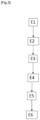
- FIG. 1 schematically represents a view from the exterior of the vehicle of a side door 100 in a position installed on the vehicle, with in this view the exterior panel of the door 100 which is not shown.
- the door 100 further comprises an intermediate reinforcement 2 arranged longitudinally inside the box 101 of the door, and extending between the front wall 102 and the rear wall 103, distant from the frieze reinforcement 1.
- the intermediate reinforcement 2 is arranged in the door box 101 in the vehicle situation in a vertical position lower than that of the frieze reinforcement 1.
- the door box 101 also comprises an exterior opening control 50 and a support 5 for the exterior opening control 50.
- the support 5 is arranged inside the door box 101.
- the external opening control support 5 is arranged between the frieze reinforcement 1 and the intermediate reinforcement 2 and comprises areas for fixing to the frieze reinforcement 1 and comprises areas for fixing to the intermediate reinforcement 2, so as to be fixed on one side to the frieze reinforcement 1 and on the other to the intermediate reinforcement 2.
- the door box 101 comprises an outer panel 4.
- the support 5 is arranged between the frieze reinforcement 1 and the outer panel 4 of the door.
- the support 5 is arranged between the intermediate reinforcement 2 and the outer panel of the door.
- the box 101 of the door 100 comprises a low reinforcement 3 arranged within the box longitudinally between the front wall 102 and the rear wall 103 of the box 101, in the lower part of the box 101 and connecting the fixing zone of the hinges of the door at the level of the front wall with the low corner at the rear of the box 101 of the door, in this other variant the intermediate reinforcement 2 being arranged vertically, in vehicle situation, between the frieze reinforcement 1 and the low reinforcement 3.
- the handle 51 of the exterior opening control 50 is of the “flush” type. That is to say that the exterior wall, in the vehicle situation, of the handle 51 in the non-use position does not protrude from the exterior panel 4 and therefore remains flush with this exterior panel 4.
- the frieze reinforcement 1 and the intermediate reinforcement 2 each comprise flat walls, facing the areas for fixing the support 5 for controlling external opening to said reinforcements (1, 2).
- the areas for fixing the support 5 for controlling external opening comprising parallel flat portions and facing said flat walls of the reinforcements, said flat portions being intended to be respectively fixed to the flat walls of the frieze reinforcement 1 and the intermediate reinforcement 2.
- the fixing of the support 5 to the frieze reinforcement 1 and to the intermediate reinforcement 2 is carried out by a wedging mastic and/or by means of an adhesive, and/or by screwing, and/or by combination of a wedging mastic and/or a bonding means and a screwing means.
- the support 5 is fixed to the frieze reinforcement 1 by a bead of wedging mastic 6 and the support 5 is fixed to the intermediate reinforcement 2 by a bead of wedging mastic 7.
- the beads of sealing mastic 6, 7 longitudinally occupy almost all of the surfaces facing the flat walls and the flat portions.
- the packing mastic is made from a crosslinking material following a rise in temperature so as to achieve adhesion of the flat walls and flat portions in contact with the bead of packing mastic.
- the beads of sealing mastic 6, 7 are automatically deposited on the frieze reinforcement 1 and on the intermediate reinforcement 2 by means of a nozzle arranged on a robot.
- the exterior panel 4 comprises fixing means on the inside of the vehicle, the exterior opening control support 5 comprising fixing interfaces intended to cooperate with the fixing means fixed to the exterior panel.
- the outer panel 4 is fixed to the elements making up the door box 101 by crimping.
- the means for fixing the support 5 to the exterior panel 4 are fixed by means of a sealing mastic to the exterior panel 4, and/or by adhesive.
- this fixing to the exterior panel 4 to the support 5 is not visible from outside the vehicle.
- the plate 52 of the external opening control comprises pre-holding clips. These pre-holding clips hold the plate 52 in position against the support 5, while waiting for this plate 52 to be fixed to the support 5.
- the support 5 comprises interfaces intended to cooperate with said pre-holding clips so as to pre-hold the external opening control plate.
- the plate 52 is fixed to the support by screwing means.
- the pre-retaining clips are made of plastic or elastomer materials and comprise a deformable part intended to engage in the facing interface in the external opening control support.
- step E2 the beads of sealing mastic 6, 7 are deposited on the flat walls of the frieze reinforcement 1 and the intermediate reinforcement 2, for example by a robot.
- the frieze reinforcement 1 is a sheet metal profile comprising a substantially vertical and flat wall located substantially in a longitudinal and vertical plane, this wall forming the lowest part of the frieze reinforcement 1, when the door is installed on the vehicle.
- the bead of sealing mastic e6 is arranged on this lowest and flat flat wall of the frieze reinforcement.
- the intermediate reinforcement 2 is a sheet metal profile comprising a substantially vertical and flat wall located substantially in a longitudinal and vertical plane, this wall forming the highest part of the frieze reinforcement 2, when the door is installed on the vehicle.
- the bead of sealing mastic 7 is arranged on this highest and flat flat wall of the intermediate reinforcement 2.
- the intermediate reinforcement 2 has a section in a vertical and transverse plane YZ in the shape of an “omega”.
- the fixing of the support 5 in step E4 to the exterior panel 4 is carried out by a sealing mastic.
- step E4 the outer panel 104 is crimped to the door box, and at the same time the flat portions of the support 5 come into contact with the sealing mastic beads 6 and 7.
- step E5 which involves passing through the cataphoresis bath, is to protect the elements forming the door, in particular the steel metal elements of the door casing 101, against corrosion. Passing through the cataphoresis bath causes the temperature to rise.
- This passage in cataphoresis is followed in a variant of the invention by a passage in a cooking oven allowing the cataphoresis treatment to dry.
- Step E5 due to the rise in temperature, causes crosslinking and therefore hardening of the sealing mastic beads 6, 7.
- step E6 the plate 52 is pre-held by staples on the support 5 and then the plate 52 is fixed to the support 5 by screws.
- the invention also relates to a vehicle comprising a door 100 according to the invention.
- the invention also relates to a door 100 manufactured according to the method according to the invention.
Landscapes
- Engineering & Computer Science (AREA)
- Mechanical Engineering (AREA)
- Body Structure For Vehicles (AREA)
- Power-Operated Mechanisms For Wings (AREA)
- Lock And Its Accessories (AREA)
Claims (9)
- Seitentür (100) eines Kraftfahrzeugs, die einen Kasten (101) unter einem Fensterteil aufweist, wobei der Kasten (101) Folgendes aufweist:- eine Vorderwand (102) und eine Rückwand (103),- eine Friesenstärke (1), die im oberen Teil des Kastens (101) die Vorderwand (102) mit der Rückwand (103) entlang des Fensterteils verbindet,- eine in Längsrichtung innerhalb des Türkastens (101) angeordnete Zwischenverstärkung (2), die sich zwischen der Vorderwand (102) und der Rückwand (103) erstreckt und von der Friesenstärke (1) beabstandet ist,- einen Türöffnungssteuerrahmen (5), der innerhalb des Türkastens zwischen der Friesenstärke (1) und der Zwischenverstärkung (2) angeordnet ist, dadurch gekennzeichnet, dass der Türöffnungssteuerrahmen (5) Bereiche zur Befestigung an der Friesenstärke und der Zwischenverstärkung aufweist, sodass er einerseits an der Friesenstärke und andererseits an der Zwischenverstärkung befestigt ist,und dass die Seitentür (100) eine Betätigungseinrichtung (50) zum Öffnen der Außenseite aufweist, die folgendes umfasst:- einem Griff (51),- eine am äußeren Öffnungssteuerrahmen (5) befestigte Platine (52), die bezüglich des äußeren Öffnungssteuerrahmens (5) fahrzeugseitig befestigt ist, wobei der Kasten (101) eine Außenwand (4) aufweist, wobei der Träger (5) und die Außenwand (4) jeweils eine gegenüberliegende Öffnung aufweisen, wobei der Griff durch beide Öffnungen verläuft.
- Seitentür (100) nach dem vorhergehenden Anspruch, bei der der Griff (51) der äußeren Öffnungssteuerung (50) vom Flush-Typ ist.
- Seitentür (100) nach einem der vorhergehenden Ansprüche, bei der die Friesenstütze (1) und die Zwischenverstärkung (2) jeweils ebene Wände aufweisen, die den Befestigungsbereichen des äußeren Öffnungssteuerungsträgers (5) gegenüberliegen, wobei die Befestigungsbereiche des äußeren Öffnungssteuerungsträgers (5) ebene Abschnitte aufweisen, die parallel zu den ebenen Wänden der Verstärkungen verlaufen, wobei die ebenen Abschnitte dazu bestimmt sind, an den ebenen Wänden der gegenüberliegenden Verstärkungen befestigt zu werden.
- Seitentür nach Anspruch 3, bei der die Befestigung des äußeren Öffnungssteuerungsträgers (5) an der Friesenstärke (1) und der Zwischenverstärkung (2) durch ein Keilmittel und/oder durch ein Klebemittel und/oder durch Verschrauben und/oder durch eine Kombination aus einem Keilmittel und/oder einem Klebemittel und einem Schraubmittel erfolgt.
- Seitentür nach Anspruch 3, bei der die Befestigung des Trägers (5) an der Friesenstärke (1) durch eine Keilkeilschnur (6) und die Befestigung des Trägers (5) an der Zwischenstärke (2) durch eine Keilkeilschnur (7) erfolgt.
- Seitentür nach einem der vorhergehenden Ansprüche, bei der die Tür eine äußere Platte (4) aufweist, die durch Crimpen an dem Türkasten (101) befestigt ist, wobei die äußere Platte (4) an der Innenseite des Fahrzeugs Befestigungsmittel aufweist, wobei der äußere Öffnungssteuerungsträger (5) Befestigungsschnittstellen zum Zusammenwirken mit den Befestigungsmitteln aufweist, die an der äußeren Platte (4) befestigt sind.
- Seitentür nach einem der vorhergehenden Ansprüche, bei der die äußere Öffnungssteuerplatine (52) Vorhalteklammern aufweist, wobei der Träger (5) Schnittstellen zum Zusammenwirken mit den Klammern aufweist, um die äußere Öffnungssteuerplatine (52) vor ihrer Befestigung an dem Träger (5) zu halten, wobei vorzugsweise die Platine (52) an dem Träger (5) durch Schrauben befestigt ist.
- Verfahren zum Herstellen einer Seitentür (100) nach Anspruch 7 und einem der Ansprüche 3 bis 5, das die folgenden aufeinander folgenden Schritte umfasst:- E1: Zusammenbau des Türkastens (101) und der Friesenstütze (1) und der Zwischenstütze (2) während des Beschlagvorgangs,- E2: Anbringen von Keilkordeln (6, 7) jeweils an den ebenen Wänden der Friesenstärke (1) und der Zwischenverstärkung (2), die den ebenen Abschnitten des Trägers (5) gegenüberliegen,- E3: Befestigung der Halterung (5) an der äußeren Türverkleidung (4),- E4: Zusammenbau der Türaußenverkleidung (4) mit dem Türkasten (101) durch Crimpen, wobei die ebenen Teile des Trägers an den Keilkittschnüren (6, 7) anliegen,- E5: Durchgang der Tür durch ein Kataphoresebad, um die Tür vor Korrosion zu schützen, vorzugsweise gefolgt von einem Durchgang durch einen Ofen,- E6: Vorspannen der Platine (52) auf dem Träger (5) durch Eingreifen der Vorhalteklammern in die Schnittstellen des Trägers (5) gefolgt von der Befestigung der Platine (52) an dem Träger (5), vorzugsweise durch Verschrauben.
- Fahrzeug mit einer Seitentür (100) nach einem der Ansprüche 1 bis 7.
Applications Claiming Priority (2)
| Application Number | Priority Date | Filing Date | Title |
|---|---|---|---|
| FR2013131A FR3117413B1 (fr) | 2020-12-14 | 2020-12-14 | Support de commande d’ouverture exterieure de vehicule |
| PCT/FR2021/051993 WO2022129720A1 (fr) | 2020-12-14 | 2021-11-10 | Support de commande d'ouverture exterieure de vehicule |
Publications (2)
| Publication Number | Publication Date |
|---|---|
| EP4259463A1 EP4259463A1 (de) | 2023-10-18 |
| EP4259463B1 true EP4259463B1 (de) | 2025-05-21 |
Family
ID=75539410
Family Applications (1)
| Application Number | Title | Priority Date | Filing Date |
|---|---|---|---|
| EP21819922.2A Active EP4259463B1 (de) | 2020-12-14 | 2021-11-10 | Externe öffnungssteuerungsklammer eines fahrzeugs |
Country Status (4)
| Country | Link |
|---|---|
| EP (1) | EP4259463B1 (de) |
| CN (1) | CN116583652A (de) |
| FR (1) | FR3117413B1 (de) |
| WO (1) | WO2022129720A1 (de) |
Family Cites Families (7)
| Publication number | Priority date | Publication date | Assignee | Title |
|---|---|---|---|---|
| DE1779197B1 (de) | 1968-07-17 | 1971-11-11 | Korsch Spezialfab Emil | Vorrichtung zum herstellen von hohlkoerpern aus thermoplasti schem kunststoff im extrusionsblasverfahren |
| FR2750929B1 (fr) * | 1996-07-09 | 1998-09-11 | Renault | Porte a cadre structural pour vehicule automobile |
| JP5425506B2 (ja) * | 2009-03-27 | 2014-02-26 | 本田技研工業株式会社 | ハンドル装置の取り付け構造 |
| JP6713737B2 (ja) | 2015-08-07 | 2020-06-24 | トヨタ自動車株式会社 | 車両用ドア構造 |
| JP6387982B2 (ja) * | 2016-02-19 | 2018-09-12 | マツダ株式会社 | 自動車のドア構造およびその組立て方法 |
| FR3097474B1 (fr) * | 2019-06-20 | 2021-05-28 | Psa Automobiles Sa | Renfort horizontal de porte de véhicule automobile |
| FR3097496B1 (fr) * | 2019-06-20 | 2022-01-14 | Psa Automobiles Sa | Fixation d’un support de commande d’ouverture extérieure de porte de véhicule automobile |
-
2020
- 2020-12-14 FR FR2013131A patent/FR3117413B1/fr active Active
-
2021
- 2021-11-10 CN CN202180084089.2A patent/CN116583652A/zh active Pending
- 2021-11-10 EP EP21819922.2A patent/EP4259463B1/de active Active
- 2021-11-10 WO PCT/FR2021/051993 patent/WO2022129720A1/fr not_active Ceased
Also Published As
| Publication number | Publication date |
|---|---|
| WO2022129720A1 (fr) | 2022-06-23 |
| CN116583652A (zh) | 2023-08-11 |
| FR3117413A1 (fr) | 2022-06-17 |
| FR3117413B1 (fr) | 2024-07-05 |
| EP4259463A1 (de) | 2023-10-18 |
Similar Documents
| Publication | Publication Date | Title |
|---|---|---|
| EP2300250B1 (de) | Öffnung, insbesondere heckklappe für ein kraftfahrzeug | |
| EP3388266B1 (de) | Tür eines kraftfahrzeugs | |
| EP3817936A1 (de) | Kofferaumdeckelbauteil für ein kraftfahrzeug | |
| EP4259463B1 (de) | Externe öffnungssteuerungsklammer eines fahrzeugs | |
| FR3063695A1 (fr) | Enjoliveur d'un montant de parebrise de vehicule automobile, muni d'une doublure interieure a supports d'agrafes mobiles l'un par rapport a l'autre. | |
| EP3953238B1 (de) | Verfahren zur befestigung von unteren und oberen strukturteilen mit verstärkungsteilen eines fahrzeuges. | |
| FR3035035A1 (fr) | Dispositif de renfort d'un hayon de vehicule automobile en matiere thermoplastique. | |
| FR3066170A1 (fr) | Renfort superieur de custode | |
| WO2018130753A1 (fr) | Structure de bas de caisse pour vehicule automobile | |
| FR2922509A1 (fr) | Cote d'habitacle de carrosserie pour vehicule automobile | |
| EP3917806B1 (de) | Fahrzeug mit fensterabdeckung montiert durch klinken | |
| EP3501954B1 (de) | Einteilige bodenstruktur aus verbundmaterial | |
| FR2934538A1 (fr) | Caisse de vehicule automobile et vehicule comprenant une telle caisse. | |
| FR3091208A1 (fr) | Renfort de caisson de porte de coffre | |
| FR2902384A1 (fr) | Dispositif enjoliveur entre une vitre fixe et un element de carrosserie d'un vehicule automobile | |
| EP1586496B1 (de) | Kraftfahrzeugdach und damit ausgestattetes Kraftfahrzeug | |
| EP1813512B1 (de) | Windschutzscheibepfosten und sein Herstellungsverfahren | |
| FR2944484A1 (fr) | Support de retroviseur et vehicule equipe d'un tel support | |
| EP2760727B1 (de) | Ersatzradmulde und montageverfahren in verbindung mit der dämperbefestigung | |
| EP1735207B1 (de) | Anordnung zur befestigung einer mechanischen verstärkungskomponente für ein kraftfahrzeug an einem seitenglied | |
| EP4592144A1 (de) | Zierblende für den radkasten eines kraftfahrzeuges | |
| WO2021260292A1 (fr) | Procédé de fixation d'un élément allongé sur un élément de structure d'un véhicule permettant une gestion de la dilatation différentielle | |
| FR3102538A1 (fr) | Ensemble de feu arrière de véhicule automobile | |
| FR2933369A1 (fr) | Chassis de vehicule automobile renforce | |
| WO2017046519A1 (fr) | Hayon de véhicule avec élément d'interface renforcé |
Legal Events
| Date | Code | Title | Description |
|---|---|---|---|
| STAA | Information on the status of an ep patent application or granted ep patent |
Free format text: STATUS: UNKNOWN |
|
| STAA | Information on the status of an ep patent application or granted ep patent |
Free format text: STATUS: THE INTERNATIONAL PUBLICATION HAS BEEN MADE |
|
| PUAI | Public reference made under article 153(3) epc to a published international application that has entered the european phase |
Free format text: ORIGINAL CODE: 0009012 |
|
| STAA | Information on the status of an ep patent application or granted ep patent |
Free format text: STATUS: REQUEST FOR EXAMINATION WAS MADE |
|
| 17P | Request for examination filed |
Effective date: 20230606 |
|
| AK | Designated contracting states |
Kind code of ref document: A1 Designated state(s): AL AT BE BG CH CY CZ DE DK EE ES FI FR GB GR HR HU IE IS IT LI LT LU LV MC MK MT NL NO PL PT RO RS SE SI SK SM TR |
|
| RAP3 | Party data changed (applicant data changed or rights of an application transferred) |
Owner name: STELLANTIS AUTO SAS |
|
| DAV | Request for validation of the european patent (deleted) | ||
| DAX | Request for extension of the european patent (deleted) | ||
| GRAP | Despatch of communication of intention to grant a patent |
Free format text: ORIGINAL CODE: EPIDOSNIGR1 |
|
| STAA | Information on the status of an ep patent application or granted ep patent |
Free format text: STATUS: GRANT OF PATENT IS INTENDED |
|
| INTG | Intention to grant announced |
Effective date: 20250130 |
|
| GRAS | Grant fee paid |
Free format text: ORIGINAL CODE: EPIDOSNIGR3 |
|
| GRAA | (expected) grant |
Free format text: ORIGINAL CODE: 0009210 |
|
| STAA | Information on the status of an ep patent application or granted ep patent |
Free format text: STATUS: THE PATENT HAS BEEN GRANTED |
|
| AK | Designated contracting states |
Kind code of ref document: B1 Designated state(s): AL AT BE BG CH CY CZ DE DK EE ES FI FR GB GR HR HU IE IS IT LI LT LU LV MC MK MT NL NO PL PT RO RS SE SI SK SM TR |
|
| REG | Reference to a national code |
Ref country code: GB Ref legal event code: FG4D Free format text: NOT ENGLISH |
|
| REG | Reference to a national code |
Ref country code: CH Ref legal event code: EP |
|
| REG | Reference to a national code |
Ref country code: DE Ref legal event code: R096 Ref document number: 602021031224 Country of ref document: DE |
|
| REG | Reference to a national code |
Ref country code: IE Ref legal event code: FG4D Free format text: LANGUAGE OF EP DOCUMENT: FRENCH |
|
| REG | Reference to a national code |
Ref country code: DE Ref legal event code: R084 Ref document number: 602021031224 Country of ref document: DE |
|
| REG | Reference to a national code |
Ref country code: NL Ref legal event code: MP Effective date: 20250521 |
|
| PG25 | Lapsed in a contracting state [announced via postgrant information from national office to epo] |
Ref country code: ES Free format text: LAPSE BECAUSE OF FAILURE TO SUBMIT A TRANSLATION OF THE DESCRIPTION OR TO PAY THE FEE WITHIN THE PRESCRIBED TIME-LIMIT Effective date: 20250521 Ref country code: FI Free format text: LAPSE BECAUSE OF FAILURE TO SUBMIT A TRANSLATION OF THE DESCRIPTION OR TO PAY THE FEE WITHIN THE PRESCRIBED TIME-LIMIT Effective date: 20250521 Ref country code: PT Free format text: LAPSE BECAUSE OF FAILURE TO SUBMIT A TRANSLATION OF THE DESCRIPTION OR TO PAY THE FEE WITHIN THE PRESCRIBED TIME-LIMIT Effective date: 20250922 |
|
| REG | Reference to a national code |
Ref country code: LT Ref legal event code: MG9D |
|
| PG25 | Lapsed in a contracting state [announced via postgrant information from national office to epo] |
Ref country code: NO Free format text: LAPSE BECAUSE OF FAILURE TO SUBMIT A TRANSLATION OF THE DESCRIPTION OR TO PAY THE FEE WITHIN THE PRESCRIBED TIME-LIMIT Effective date: 20250821 Ref country code: GR Free format text: LAPSE BECAUSE OF FAILURE TO SUBMIT A TRANSLATION OF THE DESCRIPTION OR TO PAY THE FEE WITHIN THE PRESCRIBED TIME-LIMIT Effective date: 20250822 |
|
| PG25 | Lapsed in a contracting state [announced via postgrant information from national office to epo] |
Ref country code: NL Free format text: LAPSE BECAUSE OF FAILURE TO SUBMIT A TRANSLATION OF THE DESCRIPTION OR TO PAY THE FEE WITHIN THE PRESCRIBED TIME-LIMIT Effective date: 20250521 Ref country code: PL Free format text: LAPSE BECAUSE OF FAILURE TO SUBMIT A TRANSLATION OF THE DESCRIPTION OR TO PAY THE FEE WITHIN THE PRESCRIBED TIME-LIMIT Effective date: 20250521 |
|
| PG25 | Lapsed in a contracting state [announced via postgrant information from national office to epo] |
Ref country code: BG Free format text: LAPSE BECAUSE OF FAILURE TO SUBMIT A TRANSLATION OF THE DESCRIPTION OR TO PAY THE FEE WITHIN THE PRESCRIBED TIME-LIMIT Effective date: 20250521 |
|
| PG25 | Lapsed in a contracting state [announced via postgrant information from national office to epo] |
Ref country code: HR Free format text: LAPSE BECAUSE OF FAILURE TO SUBMIT A TRANSLATION OF THE DESCRIPTION OR TO PAY THE FEE WITHIN THE PRESCRIBED TIME-LIMIT Effective date: 20250521 |
|
| PG25 | Lapsed in a contracting state [announced via postgrant information from national office to epo] |
Ref country code: RS Free format text: LAPSE BECAUSE OF FAILURE TO SUBMIT A TRANSLATION OF THE DESCRIPTION OR TO PAY THE FEE WITHIN THE PRESCRIBED TIME-LIMIT Effective date: 20250821 |
|
| PG25 | Lapsed in a contracting state [announced via postgrant information from national office to epo] |
Ref country code: IS Free format text: LAPSE BECAUSE OF FAILURE TO SUBMIT A TRANSLATION OF THE DESCRIPTION OR TO PAY THE FEE WITHIN THE PRESCRIBED TIME-LIMIT Effective date: 20250921 |
|
| PG25 | Lapsed in a contracting state [announced via postgrant information from national office to epo] |
Ref country code: LV Free format text: LAPSE BECAUSE OF FAILURE TO SUBMIT A TRANSLATION OF THE DESCRIPTION OR TO PAY THE FEE WITHIN THE PRESCRIBED TIME-LIMIT Effective date: 20250521 |
|
| REG | Reference to a national code |
Ref country code: AT Ref legal event code: MK05 Ref document number: 1796483 Country of ref document: AT Kind code of ref document: T Effective date: 20250521 |
|
| PGFP | Annual fee paid to national office [announced via postgrant information from national office to epo] |
Ref country code: DE Payment date: 20251022 Year of fee payment: 5 |
|
| PG25 | Lapsed in a contracting state [announced via postgrant information from national office to epo] |
Ref country code: DK Free format text: LAPSE BECAUSE OF FAILURE TO SUBMIT A TRANSLATION OF THE DESCRIPTION OR TO PAY THE FEE WITHIN THE PRESCRIBED TIME-LIMIT Effective date: 20250521 Ref country code: SM Free format text: LAPSE BECAUSE OF FAILURE TO SUBMIT A TRANSLATION OF THE DESCRIPTION OR TO PAY THE FEE WITHIN THE PRESCRIBED TIME-LIMIT Effective date: 20250521 Ref country code: AT Free format text: LAPSE BECAUSE OF FAILURE TO SUBMIT A TRANSLATION OF THE DESCRIPTION OR TO PAY THE FEE WITHIN THE PRESCRIBED TIME-LIMIT Effective date: 20250521 |
|
| PGFP | Annual fee paid to national office [announced via postgrant information from national office to epo] |
Ref country code: IT Payment date: 20251022 Year of fee payment: 5 |
|
| PGFP | Annual fee paid to national office [announced via postgrant information from national office to epo] |
Ref country code: FR Payment date: 20251023 Year of fee payment: 5 |
|
| PG25 | Lapsed in a contracting state [announced via postgrant information from national office to epo] |
Ref country code: CZ Free format text: LAPSE BECAUSE OF FAILURE TO SUBMIT A TRANSLATION OF THE DESCRIPTION OR TO PAY THE FEE WITHIN THE PRESCRIBED TIME-LIMIT Effective date: 20250521 |
|
| PG25 | Lapsed in a contracting state [announced via postgrant information from national office to epo] |
Ref country code: EE Free format text: LAPSE BECAUSE OF FAILURE TO SUBMIT A TRANSLATION OF THE DESCRIPTION OR TO PAY THE FEE WITHIN THE PRESCRIBED TIME-LIMIT Effective date: 20250521 |
|
| PG25 | Lapsed in a contracting state [announced via postgrant information from national office to epo] |
Ref country code: SK Free format text: LAPSE BECAUSE OF FAILURE TO SUBMIT A TRANSLATION OF THE DESCRIPTION OR TO PAY THE FEE WITHIN THE PRESCRIBED TIME-LIMIT Effective date: 20250521 |