EP4259437B1 - Rakelwerk für eine druckvorrichtung - Google Patents
Rakelwerk für eine druckvorrichtung Download PDFInfo
- Publication number
- EP4259437B1 EP4259437B1 EP21835975.0A EP21835975A EP4259437B1 EP 4259437 B1 EP4259437 B1 EP 4259437B1 EP 21835975 A EP21835975 A EP 21835975A EP 4259437 B1 EP4259437 B1 EP 4259437B1
- Authority
- EP
- European Patent Office
- Prior art keywords
- doctoring
- printing
- doctor
- unit
- drive device
- Prior art date
- Legal status (The legal status is an assumption and is not a legal conclusion. Google has not performed a legal analysis and makes no representation as to the accuracy of the status listed.)
- Active
Links
Images


Classifications
-
- B—PERFORMING OPERATIONS; TRANSPORTING
- B41—PRINTING; LINING MACHINES; TYPEWRITERS; STAMPS
- B41F—PRINTING MACHINES OR PRESSES
- B41F15/00—Screen printers
- B41F15/14—Details
- B41F15/44—Squeegees or doctors
- B41F15/46—Squeegees or doctors with two or more operative parts
-
- B—PERFORMING OPERATIONS; TRANSPORTING
- B41—PRINTING; LINING MACHINES; TYPEWRITERS; STAMPS
- B41F—PRINTING MACHINES OR PRESSES
- B41F15/00—Screen printers
- B41F15/08—Machines
- B41F15/0804—Machines for printing sheets
- B41F15/0813—Machines for printing sheets with flat screens
- B41F15/0818—Machines for printing sheets with flat screens with a stationary screen and a moving squeegee
-
- H—ELECTRICITY
- H05—ELECTRIC TECHNIQUES NOT OTHERWISE PROVIDED FOR
- H05K—PRINTED CIRCUITS; CASINGS OR CONSTRUCTIONAL DETAILS OF ELECTRIC APPARATUS; MANUFACTURE OF ASSEMBLAGES OF ELECTRICAL COMPONENTS
- H05K3/00—Apparatus or processes for manufacturing printed circuits
- H05K3/10—Apparatus or processes for manufacturing printed circuits in which conductive material is applied to the insulating support in such a manner as to form the desired conductive pattern
- H05K3/12—Apparatus or processes for manufacturing printed circuits in which conductive material is applied to the insulating support in such a manner as to form the desired conductive pattern using thick film techniques, e.g. printing techniques to apply the conductive material or similar techniques for applying conductive paste or ink patterns
- H05K3/1216—Apparatus or processes for manufacturing printed circuits in which conductive material is applied to the insulating support in such a manner as to form the desired conductive pattern using thick film techniques, e.g. printing techniques to apply the conductive material or similar techniques for applying conductive paste or ink patterns by screen printing or stencil printing
- H05K3/1233—Methods or means for supplying the conductive material and for forcing it through the screen or stencil
-
- B—PERFORMING OPERATIONS; TRANSPORTING
- B41—PRINTING; LINING MACHINES; TYPEWRITERS; STAMPS
- B41P—INDEXING SCHEME RELATING TO PRINTING, LINING MACHINES, TYPEWRITERS, AND TO STAMPS
- B41P2215/00—Screen printing machines
- B41P2215/50—Screen printing machines for particular purposes
-
- H—ELECTRICITY
- H05—ELECTRIC TECHNIQUES NOT OTHERWISE PROVIDED FOR
- H05K—PRINTED CIRCUITS; CASINGS OR CONSTRUCTIONAL DETAILS OF ELECTRIC APPARATUS; MANUFACTURE OF ASSEMBLAGES OF ELECTRICAL COMPONENTS
- H05K2203/00—Indexing scheme relating to apparatus or processes for manufacturing printed circuits covered by H05K3/00
- H05K2203/01—Tools for processing; Objects used during processing
- H05K2203/0104—Tools for processing; Objects used during processing for patterning or coating
- H05K2203/0139—Blade or squeegee, e.g. for screen printing or filling of holes
Definitions
- the invention relates to a doctor blade unit for a printing device for printing flat substrates, in particular circuit boards, wafers or solar cells, with two doctor blades which extend parallel to each other and are pivotably mounted.
- the invention relates to a doctor blade device for a printing device for printing flat substrates, in particular circuit boards, wafers or solar cells, with a doctor blade unit and with a drive device for operating the doctor blade unit.
- the invention relates to a printing device for printing flat substrates, in particular printed circuit boards, wafers or solar cells, with a doctor device, with a printing screen holder on which a printing screen or a printing mask can be or is arranged, and with a printing table on which the substrate to be printed can be arranged on the side of the printing screen holder facing away from the doctor device.
- Doctor blades are used to print flat substrates such as circuit boards or wafers, which make it possible to print predetermined patterns, such as conductor tracks or the like, in large quantities in a short period of time.
- the printing material is placed on a printing screen or a printing mask, which can also be made of an electrically conductive material, for example, whereby the printing mask or the printing screen has openings or free spaces that correspond to the desired print image. If the doctor blade is then moved over the screen with one or more doctor blades, the printing material is pressed through the printing screen or the printing mask or printing stencil and thus applied to the substrate.
- Doctor blade units which have two doctor blades which extend parallel to each other but are inclined in opposite directions to each other, so that one doctor blade interacts with the printing mass when moved in a first direction, and the second doctor blade interacts when the doctor blades are moved in the opposite direction.
- the doctor blade unit In order to change the printing material, the doctor blade unit must be freed of the printing material that was previously used or cleaned. To do this, for example, the doctor blades and the printing screen or the printing mask are removed from the doctor blade unit and cleaned outside of the printing device. Printing material that remains on the doctor blades after the previous printing process can be lost both when removing and when transporting the doctor blade unit. The printing material is then lost for further printing processes during cleaning at the latest.
- the invention is based on the object of creating an improved doctor blade unit in which a loss of printing mass when replacing the doctor blade unit or the printing mass is reduced.
- the problem underlying the invention is solved by a doctor blade unit with the features of claim 1.
- the doctor blade unit according to the invention has the advantage that a larger amount of printing material can be safely stored or transported with the doctor blade unit, in particular even when the entire doctor blade unit is removed from the printing device.
- the invention ensures that printing material is safely held in the doctor blade unit and can, for example, be reused in a targeted manner.
- the invention also allows the doctor blade unit to be transferred from one printing device to another printing device and in the process printing material, in particular solder paste, to be transferred from one printing screen to another printing screen, even to another printing device. This saves the user material costs, avoids waste and reduces the proportion of doctor blade units circulating in production. If the doctor blade unit can also be exchanged fully automatically, a higher degree of automation in production results.
- the doctor blades are pivotably mounted, in particular pivotable in opposite directions, so that the doctor blade angle can be adjusted in relation to the printing screen or the printing mask, and in that the doctor blades are operatively connected to a gear that is self-locking and can be coupled or is coupled to a drive device.
- the gear thus enables the doctor angle to be adjusted using the drive device.
- the doctor blades are preferably also operatively connected to one another by the gear, the doctor angle of both doctor blades is adjusted simultaneously by the same gear and the same drive device.
- the gear is designed to be self-locking, the doctor blades maintain the doctor angle once set, especially when the drive device is disconnected from the gear. This means that the doctor blades can be pivoted into a transport position in which the printing mass is optimally retained or kept in the doctor unit in order to replace the doctor unit or to move the doctor unit to a cleaning device without any loss of printing mass.
- the doctor blades are particularly preferably arranged on the doctor frame and the gear is designed in such a way that the doctor blades can be pivoted by the gear into a V-shaped position in which the doctor blades lie against one another at their free doctor edges.
- the doctor edges are understood here to be the longitudinal edges of the doctor blades which, during operation, are assigned to the printing screen or printing mask and press the printing compound through the printing mask or the printing screen.
- the doctor blades By pivoting into the V-shaped position, the doctor blades together enclose a V-shaped space which is closed at its pointed end by the doctor edges lying against one another. Printing compound located on the doctor blades cannot therefore escape from this space in the area of the doctor edges.
- a type of printing compound pocket is thus formed in the doctor unit, with the help of which the printing compound can be safely held back, for example to carry out a stencil or screen change or to replace the doctor unit as a whole.
- the gear is designed as a worm gear. This allows the self-locking of the gear to be implemented safely and cost-effectively in a simple and known manner.
- the worm gear can transmit high actuating forces and ensures a high level of robustness against unintentional adjustment of the squeegee angle.
- each doctor blade is arranged on a rotatably mounted shaft for pivoting, with a worm wheel of the worm gear being arranged on each of the shafts in a rotationally fixed manner, which is in engagement with a worm shaft of the worm gear that is connected or can be connected to the drive.
- This allows the doctor blades to be adjusted using the gear.
- adjusting the doctor blades without the worm shaft being driven is prevented by the self-locking.
- the shafts are preferably integrally formed in the respective doctor blade, so that the doctor blades, for example, on their long sides facing away from the doctor blade's effective edge, have the
- the respective shaft itself can also be formed by shaft stubs protruding from the front sides of the respective doctor blade, for example, which can be inserted into a bearing receptacle, for example in the bearing frame, for pivotable mounting.
- the respective worm wheel is formed in one piece with the respective doctor blade and does not form a complete worm wheel, but rather a worm wheel that extends over less than 360° in circumference.
- the respective doctor blade is pushed onto a continuous shaft and is either rotatably mounted on the shaft, or the shaft is rotatably mounted in the bearing receptacle, for example in the doctor frame.
- the worm wheel is then either connected in a rotationally fixed manner to the doctor blade and/or in a rotationally fixed manner to the shaft.
- the gear has a drive shaft which is coupled on the one hand to the worm shaft and on the other hand has a coupling end which is designed for the detachable coupling of the drive shaft to the drive device.
- the drive shaft is in particular coupled to the worm shaft in a rotationally fixed manner, so that a drive force acting on the drive shaft, in particular a drive torque, is exerted directly on the worm shaft in order to pivot the doctor blades.
- the drive shaft can be detachably connected to the drive device through the coupling end.
- the doctor unit as a whole can be advantageously detached from the drive device, whereby the self-locking of the gear takes effect when it is released and prevents further adjustment of the doctor blades on the doctor blades themselves.
- the coupling end also ensures that the doctor unit can be easily joined or operatively connected to the drive device.
- the coupling end is particularly preferably designed as a component of a frictional or positive-locking releasable coupling, in particular as a component of a friction clutch or claw clutch.
- the friction or claw clutch ensures that the coupling end can be easily joined to the drive device, which then preferably also has a shaft with a component of the friction clutch or claw clutch or the frictional or positive-locking coupling.
- the doctor blade unit has a housing in or on which the gear, the doctor blade carrier and the doctor blades are held, with the drive shaft being guided outwards through an opening in the housing.
- the housing protects the components of the doctor blade unit arranged in the housing, such as the gear, the doctor blade carrier and the doctor blades, from external influences.
- the drive shaft protrudes from the housing, ensuring easy coupling with the drive device.
- the drive shaft protruding from the housing can also be manually operated by a user to change the position of the doctor blades if necessary, for example for cleaning purposes.
- the doctor blade unit can be operated manually by a user outside the printing device or automatically by a cleaning machine to open the receiving pocket formed by the doctor blades and release the printing compound contained therein.
- the doctor blade unit has means for detachably fastening the doctor blade unit to the drive device.
- the doctor blade unit can thus be detachably fastened to the drive device by means of the means, which enables the doctor blade unit of a printing device or the drive device to be easily replaced.
- the entire doctor blade unit can thus be easily detached from the drive device and, for example, brought to another printing device with a corresponding drive device and connected there to the drive device in order to carry out another printing process on the other printing device.
- the doctor blade unit can also be detached from the drive device and fed to a cleaning device in accordance with the printing device.
- Means for detachable fastening are understood in particular to mean means that allow the doctor blade unit to be detached or fastened to the drive device in a few simple steps, in particular without the need for tools.
- a screw connection in which the doctor blade unit could be fastened to the drive device by a fastening screw is not understood in this context as a means for detachable fastening, but as a permanent fastening means.
- the means is particularly preferably designed as a locking means.
- the locking means preferably has one or more elastically displaceable locking elements which can be brought into a position that holds the doctor blade unit positively to the drive device under elastic deformation.
- the means preferably also have depressions or notches, for example formed in the housing or the drive device, in order to interact positively with an elastically displaceable locking element of the drive device or the housing.
- the respective elastically displaceable or deformable locking element can therefore be arranged on the doctor blade unit itself or on the drive device. The depression or notch is then arranged or formed on the other device.
- the doctor blade unit has a drive device which has at least one drive machine, in particular an electric machine, which can be coupled or is coupled to the transmission, in particular to the drive shaft of the transmission.
- the drive device is in particular the drive device described above, to which the rest of the doctor blade unit can be detachably connected.
- the drive device is integrated into a printing device, which in particular also has a printing table on which the substrate to be printed can be arranged.
- the drive machine preferably has an output shaft which has an end that is coupled or can be coupled to the transmission.
- the end of the output shaft can thus be detachably connected to the coupling end of the drive shaft.
- the coupling end and the end together form a positively locking or a frictionally locking clutch, in particular a claw clutch or a friction clutch.
- doctor blade device with the features of claim 7 is characterized by the design of the doctor blade unit according to the invention.
- the doctor blade unit is or can be detachably coupled to the drive device.
- the drive device and/or the doctor blade unit have the above-mentioned means for easy joining and detaching of the doctor blade unit and the drive device in order to ensure easy replacement of the doctor blade unit.
- the means are designed as locking means, as described above.
- the drive device particularly preferably has a doctor blade holder that can be detachably connected to the doctor blade.
- the doctor blade holder has the means or part of the means for detachably fastening the doctor blade, so that the doctor blade is or can be detachably fastened to the frame holder.
- the doctor blade holder thus represents the interface between the doctor blade and the drive device and serves to accommodate and store the doctor blade.
- the detachable connection is designed in particular as described above, in particular with at least one elastically deformable or displaceable locking element.
- the doctor blade holder is preferably mounted so that it can pivot about a central axis that is aligned parallel to the shafts of the doctor blade. By pivoting the doctor blade holder about the central axis, the doctor blade attached to the doctor blade holder is also pivoted, which means that the doctor blade can be optimally adjusted in its orientation to the printing to be carried out during a printing process.
- the doctor blade holder is pivoted in one direction or the other depending on the direction in which the doctor blades are moved in order to achieve an optimal doctoring result.
- a controllable actuator for pivoting the doctor blade holder is assigned to the doctor blade holder on at least one projection of the doctor blade holder remote from the central axis.
- the doctor blade holder can thus be influenced or adjusted in its pivoting position by means of the actuator in order to achieve the precise printing result.
- the doctor blade holder has projections arranged remotely on both sides of the central axis, each of which is assigned a controllable actuator.
- the actuator is particularly preferably designed as a pneumatic actuator with a lifting piston associated with the projection, which acts on the projection in particular tangentially to the central axis.
- the actuator is given elasticity by the compressible pneumatic medium. This ensures that the doctor blade unit can be pivoted or moved against the force of the actuator if an excessive resistance force occurs when moving the doctor blades, so that damage to the doctor blades is reliably avoided.
- the pneumatic actuator thus acts in the manner of a pre-tension on the doctor frame. In particular, the entire doctor blade unit can be pivoted and moved against the pre-tensioning force of the actuator.
- the printing device according to the invention with the features of claim 15 is characterized by the inventive design of the doctor device.
- the doctor unit is or can be attached to the drive device in an exchangeable manner using the means mentioned above.
- the doctor unit, together with the doctor device, forms in particular the print head of the printing device.
- a printing system is also created in which several printing devices are present, each of which has a drive device to which the doctor unit according to the invention can be attached.
- Figure 1 shows in a simplified side view an advantageous doctor device 1 for a printing device 2 (not shown in detail here) for printing on flat substrates, in particular printed circuit boards, wafers or the like.
- the doctor device 1 is designed to apply printing material through openings or structures of a printing screen 3, which is in Figure 1 is only indicated, and thus to apply it to one or more substrates located under the printing screen 3.
- the doctor device 1 has a doctor unit 4 which carries two doctor blades 5, 6.
- the doctor blades 5, 6 extend perpendicular to the image plane, wherein the doctor blades 5, 6 are each held with a longitudinal edge on a doctor carrier 9 of the doctor unit 4 and form a doctor effective edge 7, 8 on their longitudinal edge facing away from this longitudinal edge, which serves to sweep over the printing mass or the printing screen 3.
- the doctor blades 5, 6 can be made of metal or plastic and can be rigid or slightly elastically deformable.
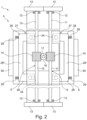
- FIG 2 shows the doctor blade unit 4 in a simplified top view.
- the doctor blade unit 4 has the doctor blade carrier 9, on which the doctor blades 5, 6 are pivotably mounted.
- the doctor blades 5, 6 are each connected to a rotatably mounted shaft 10, 11 at their end applied by the doctor blade active edge 7, 8 or are attached to it in a rotationally fixed manner, so that a rotation of the respective shaft 11, 10 leads to a corresponding adjustment of the doctor angle ⁇ 5 or ⁇ 6 of the respective doctor blade 5, 6, as in Figure 1 shown.
- the shafts 10, 11 have, for example, radial slots in which the doctor blades 5, 6 are inserted.
- the shafts 10, 11 are advantageously rotatably mounted by several rolling element bearings 12, so that rotation occurs with little friction loss.
- paste limiters 13 are assigned to the front of the doctor blades 5, 6, which prevent the applied printing paste from escaping laterally past the doctor blades 5, 6 when the printing screen 3 is swept over.
- the shafts 10, 11 each carry a worm gear 14, 15, which is connected in a rotationally fixed manner to the respective shaft 5, 6.
- the worm gears 14, 15 are arranged centrally on the shafts 5, 6 - viewed in the longitudinal extension of the shafts 5, 6 - as shown in Figure 2 shown.
- the worm gears 14, 15 are thus parallel to one another.
- a worm shaft 16 is arranged, which meshes with the two worm gears 14, 15.
- the worm shaft 16 is rotatably mounted on the doctor blade carrier 9 by a further roller bearing 12.
- the worm shaft 16 merges into a drive shaft 17, i.e.
- the doctor blade carrier 9 forms the housing 18.
- the housing 18 is trough-shaped, as shown for example in Figure 1 shown, with the drive shaft 17 penetrating the bottom of the tub mold and enclosing at least the shafts 10, 11 and the worm gears 14, 15 so that they are protected from external influences.
- the housing 18 is open so that the doctor blades 5, 6 emerge from the housing 18 and can be pivoted, as in Figure 1 shown.
- the drive shaft 17 has a coupling end 19 at its end facing away from the worm shaft 16.
- the coupling end 19 is characterized in that it has an outer diameter that increases with increasing distance from the worm shaft 16 and has a recess 20 on its free end face, so that the coupling end 19 is designed in the manner of a hollow shaft that widens in a V-shape when viewed in longitudinal section. This results in a kind of funnel shape of the coupling end 19.
- the coupling end 19 advantageously has a driving structure on its inner side 21, for example in the form of grooves, grooves, projections or teeth.
- the drive shaft 17 does have the recess 20, but does not widen on its outer side, so that a particularly V-shaped recess 20 is formed on the end face and the outer shell wall of the shaft remains cylindrical in the area of the coupling end 19.
- the doctor device 1 further comprises a drive device 22 which is arranged above the doctor unit 4, as shown in Figure 1 shown.
- the drive device 22 has, for example, an electric motor 23 which is connected directly or through a gear to an output shaft 24.
- the output shaft 24 protrudes from a housing of the electric motor 23 in the direction of the doctor blade unit 4 and has an end 25 which serves to be detachably connected to the coupling end 19 of the doctor blade unit 4.
- the end 25 is preferably designed to be complementary to the coupling end 19, according to the present embodiment as a truncated cone whose cone angle corresponds approximately to the opening angle of the V-shaped coupling end 19, preferably the truncated cone angle is slightly smaller.
- the coupling end 19 can be easily pushed onto the end 25 of the output shaft 24.
- the coupling end 19 together with the end 25 form a detachable coupling 26.
- the coupling 26 is designed as a friction clutch.
- the coupling 26 is designed as a claw coupling or a positive-locking coupling. This is particularly achieved by the optional grooves, teeth or channels on the inner side 21, which engage with corresponding projections, grooves, or teeth on the end 25. This ensures a positive torque transmission from the drive device 22 to the worm shaft 16.
- the recess 20 is formed in the end 25 and the coupling end 19 has a complementary truncated cone. It is also conceivable that the end 25 and the coupling end 19 each have a flat front side in a plane perpendicular to the axis of rotation, which are pressed against one another, for example, to form the friction clutch or also have a toothing for positive torque transmission or torque drive.
- the detachable coupling 26 enables the doctor blade unit 4 to be easily removed from the drive device 22.
- means 27 are also provided for detachably connecting the doctor blade unit 4 to the drive device 2.
- the means 27 in the present case have a plurality of elastically displaceable locking elements 28. According to the present embodiment, these are arranged on the drive device 22 and mounted so as to be laterally displaceable or parallel to the plane of the printing screen 3.
- the locking elements 28 are designed in the form of locking wedges, which are each held in place by a pre-tensioning spring 29 are subjected to a spring force in the direction of the output shaft 24.
- at least two locking elements 28 are mounted opposite one another on a doctor blade holder 30 of the drive device 22, to which the doctor blade 4 is detachably attached by the means 27.
- the doctor blade unit 4 has a number of counter-locking elements 31 corresponding to the number of locking elements 28.
- the counter-locking elements 31 are, for example, fastened in the frame and/or the housing 18 and protrude from the housing 18 essentially parallel to the drive shaft 17.
- the counter-locking elements 31 each have a lateral notch 32, wherein the notches 32 of the opposing counter-locking elements 31 face away from each other and thus face the respective locking element 28.
- the notches 32 are designed to be large enough to accommodate a section of the respective locking element 28, as shown in particular in Figure 3 shown.
- the counter-latching elements 31 have an insertion bevel 33 or run-on bevel on their end face facing away from the housing 9, by means of which the respective latching element 28 is pushed back against the force of the pre-tensioning spring 29 when the doctor blade unit 4 is fed to the drive device 22.
- the latching elements 28 also each have a run-on bevel 34 or insertion bevel, which interacts with the insertion bevel 33 of the respective latching element 31.
- the respective locking element 28 is pushed into the respective notch by the spring force of the pre-tensioning spring 29.
- the doctor blade unit 4 is held positively on the drive device 22 and is operatively connected to the electric motor 23 by the coupling 26.
- the locking elements 28 are pushed back against the force of the respective pre-tensioning spring 29 and thus removed from the respective notch 33, after which the doctor blade unit 4 can simply be pulled downwards from the drive device 22.
- the operative connection between the coupling end 19 and the output shaft 24 is also released without any further measures, in particular without tools. Because the gear 35 formed by worm gears 14, 15 and worm shaft 16 is self-locking, the doctor blades 5, 6 remain in their last set pivot position after the doctor unit 4 has been removed from the drive device 22. The pivot position on the doctor unit 4 can then also be changed manually by a user by manually applying a torque to the coupling end 19.
- the doctor blades 5, 6 are brought into a transport position in which the doctor blades are arranged in a V-shape inclined to one another so that their free doctor edges 7, 8 abut one another, as in Figure 1 shown.
- Figure 1 shows the doctor blade in the V-shaped transport position with solid lines and in other example doctor blade positions with dashed lines.
- the self-locking mechanism of the gear 35 ensures that the doctor blades 5, 6 remain in the transport position, so that any printing compound located between the doctor blades 5, 6 is picked up and stored between the doctor blades.
- the printing compound cannot leave the space formed between the doctor blades 5, 6 and the lateral paste limiters 13. This ensures safe transport of the printing compound or paste, which allows, for example, the doctor unit 4 to be moved from one printing table to another without any loss of printing compound, or from one printing table to a cleaning facility, in which the remaining printing compound can then be removed in a targeted manner and prepared for reuse. This reduces the overall consumption of printing compound.
- Figure 4A shows the doctor device 1 in a simplified perspective view.
- a lifting device 36 of the printing device 2 is also shown, by means of which the drive device as a whole can be lowered and raised, as shown by a double arrow 37.
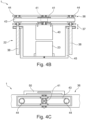
- Figure 4B shows the lifting device 36 in a side view of the doctor device 1 and Figure 4C shows a simplified top view of the lifting device 36.
- the lifting device 36 is designed as a spindle lifting device which, according to the present embodiment, has two lifting spindles 38, each of which is guided by a thread of a carrier 45 of the drive device 22, so that when the respective lifting spindle 38 rotates, the drive device is moved translationally or axially along the lifting spindle 38.
- a belt drive 39 is used in particular, which has a drive motor 40, in particular an electric motor, which is operatively connected to a drive wheel 41, and a belt 43 which is guided around several guide rollers 42, of which at least one is preferably arranged radially elastically displaceable as a tension roller, and around/on the rollers 44 attached to the ends of the lifting spindles 38, so that the torque of the drive motor 40 can be transmitted to the lifting spindles 38 by the belt 43.
- the drive device 22 with the doctor blade unit 4 arranged therein can thus be moved down onto a printing screen or a printing stencil or detached from it.
- the doctor blade holder 30 is pivotably mounted on the carrier 45 of the drive device 22.
- the doctor blade holder 30 has a bearing pin 46 on each of two opposite end faces, which is rotatably mounted in a bearing receptacle 47 of the carrier 45.
- the entire doctor blade holder 30 is pivotably mounted about an axis, which in particular, as in Figure 4A shown, is a central axis 48 and extends in particular parallel to the axes of rotation of the shafts 10, 11.
- the central axis 48 intersects in particular the central longitudinal axis of the worm shaft 16.
- At least one pneumatic actuator 49 is provided for pivoting the doctor blade holder 30, as shown by way of example in Figures 1 and 4A shown.
- the doctor blade holder 30 has two projections 50 facing away from each other, which are each arranged on the longitudinal sides of the doctor blade holder extending parallel to the central axis 48 and protrude laterally, resulting in an L-shape.
- a pneumatic actuator 49 is assigned to each of these projections.
- Each of the pneumatic actuators has a pneumatic piston 51, which interacts with the projection 50 and is displaceably mounted in a pneumatic cylinder, in particular tangentially to the central axis 48.
- the pneumatic application of force to the doctor blade holder 30 ensures that the pneumatic medium provides an elasticity that allows the doctor blade holder 30 to pivot against the direction of actuation. This allows, for example, the doctor blade 4 to pivot against the force of the actuator 49 if one of the doctor blades 5 or 6 hits an insurmountable object. This protects the doctor blades 5, 6 and guarantees a long service life for the doctor blade 4.
Landscapes
- Engineering & Computer Science (AREA)
- Mechanical Engineering (AREA)
- Manufacturing & Machinery (AREA)
- Microelectronics & Electronic Packaging (AREA)
- Screen Printers (AREA)
- Rotary Presses (AREA)
- Electroluminescent Light Sources (AREA)
Description
- Die Erfindung betrifft ein Rakelwerk für eine Druckvorrichtung zum Bedrucken von flächigen Substraten, insbesondere Leiterplatten, Wafer oder Solarzellen, mit zwei Rakelklingen, die sich parallel zueinander erstrecken und verschwenkbar gelagert sind.
- Weiterhin betrifft die Erfindung eine Rakelvorrichtung für eine Druckvorrichtung zum Bedrucken von flächigen Substraten, insbesondere Leiterplatten, Wafer oder Solarzellen, mit einem Rakelwerk und mit einer Antriebseinrichtung zum Betreiben des Rakelwerks.
- Weiterhin betrifft die Erfindung eine Druckvorrichtung zum Bedrucken von flächigen Substraten, insbesondere Leiterplatten, Wafer oder Solarzellen, mit einer Rakelvorrichtung, mit einem Drucksiebhalter, an welchem ein Drucksieb oder eine Druckmaske anordenbar oder angeordnet ist, und mit einem Drucktisch, auf welchem das zu bedruckende Substrat auf der von der Rakelvorrichtung abgewandten Seite des Drucksiebhalters anordenbar ist.
- Druckvorrichtungen und Rakelwerke der eingangs genannten Art sind aus dem Stand der Technik bereits bekannt. Zum Bedrucken von flächigen Substraten wie Leiterplatten oder Wafern werden Rakelwerke eingesetzt, durch welche das Aufdrucken vorbestimmter Muster, beispielsweise Leiterbahnen oder dergleichen, in hoher Stückzahl in kurzer Zeitdauer möglich ist. Dazu wird auf ein Drucksieb oder eine Druckmaske die Druckmasse gegeben, die beispielsweise auch aus einem elektrisch leitfähigen Material gefertigt sein kann, wobei die Druckmaske oder das Drucksieb Öffnungen oder Freiräume aufweist, die dem gewünschten Druckbild entsprechen. Wird anschließend das Rakel mit einer oder mehreren Rakelklingen über das Sieb verschoben, so wird dadurch die Druckmasse durch das Drucksieb oder die Druckmaske oder Druckschablone hindurch gedrückt und damit auf das Substrat aufgebracht. Es sind Rakelwerke bekannt, die zwei Rakelklingen aufweisen, die sich parallel zueinander erstrecken, jedoch gegenläufig zueinander geneigt ausgerichtet sind, sodass die eine Rakelklinge beim Verschieben in eine erste Richtung mit der Druckmasse zusammenwirkt, und die zweite Rakelklinge beim Verschieben der Rakelklingen in die entgegengesetzte Richtung.
- Aus der Offenlegungsschrift
KR 2019 0052775 A - Um einen Druckmassenwechsel vorzunehmen, muss das Rakelwerk von der bisher verwendeten Druckmasse befreit beziehungsweise gereinigt werden. Dazu werden beispielsweise die Rakelklingen sowie das Drucksieb oder die Druckmaske aus dem Rakelwerk entnommen und außerhalb der Druckvorrichtung gereinigt. Sowohl bei der Entnahme als auch beim Transport des Rakelwerks kann Druckmasse verloren gehen, die nach dem zuvor erfolgten Druckvorgang an den Rakelklingen verblieben ist. Spätestens in der Reinigung geht die Druckmasse dann für weitere Druckvorgänge verloren.
- Der Erfindung liegt die Aufgabe zugrunde, ein verbessertes Rakelwerk zu schaffen, bei dem ein Druckmassenverlust beim Austausch des Rakelwerks oder der Druckmasse reduziert wird.
- Die der Erfindung zugrundeliegende Aufgabe wird durch ein Rakelwerk mit den Merkmalen des Anspruchs 1 gelöst. Das erfindungsgemäße Rakelwerk hat den Vorteil, dass auch eine größere Menge von Druckmasse mit dem Rakelwerk sicher aufbewahrt oder transportiert werden kann, insbesondere auch dann, wenn das gesamte Rakelwerk von der Druckvorrichtung gelöst wird. Durch die Erfindung wird erreicht, dass Druckmasse in dem Rakelwerk sicher gehalten wird und beispielsweise gezielt einer Wiederverwendung zugeführt werden kann. Die Erfindung erlaubt es außerdem, das Rakelwerk von einer Druckvorrichtung zu einer anderen Druckvorrichtung zu überführen und dabei Druckmasse, insbesondere Lotpaste, von einem Drucksieb zu einem anderen Drucksieb, auch einer anderen Druckvorrichtung, zu übertragen. Dadurch spart der Anwender Materialkosten, vermeidet Abfall und reduziert den Anteil an in der Fertigung umlaufenden Rakelwerken. Ist das Rakelwerk außerdem vollautomatisch austauschbar, ergibt sich ein höherer Automatisierungsgrad in der Fertigung.
- Erfindungsgemäß wird dies dadurch erreicht, dass die Rakelklingen verschwenkbar gelagert sind, insbesondere gegenläufig verschwenkbar, sodass der Rakelklingenwinkel in Bezug zu dem Drucksieb oder der Druckmaske einstellbar ist, und dass die Rakelklingen mit einem Getriebe wirkverbunden sind, das selbsthemmend ausgebildet und mit einer Antriebseinrichtung koppelbar oder gekoppelt ist. Durch das Getriebe ist somit der Rakelwinkel mithilfe der Antriebseinrichtung einstellbar. Dadurch, dass die Rakelklingen durch das Getriebe bevorzugt auch miteinander wirkverbunden sind, erfolgt eine Einstellung des Rakelwinkels beider Rakelklingen gleichzeitig durch dasselbe Getriebe und dieselbe Antriebseinrichtung. Dadurch, dass das Getriebe selbsthemmend ausgebildet ist, behalten die Rakelklingen den einmal eingestellten Rakelwinkel bei, insbesondere auch dann, wenn die Antriebseinrichtung von dem Getriebe abgekoppelt ist. Dadurch sind die Rakelklingen insbesondere in eine Transportstellung verschwenkbar, in welcher die Druckmasse optimal zurückgehalten beziehungsweise in dem Rakelwerk behalten wird, um einen Austausch des Rakelwerks oder ein Verbringen des Rakelwerks zu einer Reinigungseinrichtung ohne Druckmassenverlust zu bewerkstelligen.
- Besonders bevorzugt sind die Rakelklingen derart an dem Rakelrahmen angeordnet und das Getriebe derart ausgebildet, dass die Rakelklingen durch das Getriebe in eine V-förmige Stellung verschwenkbar sind, in welcher die Rakelklingen an ihren freien Rakelwirkkanten aneinander anliegen. Unter den Rakelwirkkanten werden hierbei die Längskanten der Rakelklingen verstanden, die im Betrieb dem Drucksieb oder Druckmaske zugeordnet sind und die Druckmasse durch die Druckmaske oder das Drucksieb pressen. Durch das Verschwenken in die V-förmige Stellung schließen die Rakelklingen zusammen einen V-förmigen Raum ein, der an seinem spitzen Ende durch das Aneinanderliegen der Rakelwirkkanten verschlossen ist. Auf den Rakelklingen befindliche Druckmasse kann somit nicht aus diesem Raum im Bereich der Rakelwirkkanten entweichen. Es wird somit eine Art der Druckmassentasche in dem Rakelwerk gebildet, mithilfe welcher die Druckmasse sicher zurückgehalten werden kann, um beispielsweise einen Schablonen- oder Siebwechsel durchzuführen oder um das Rakelwerk insgesamt auszutauschen.
- Erfindungsgemäß ist das Getriebe als Schneckenradgetriebe ausgebildet. Hierdurch kann die Selbsthemmung des Getriebes auf einfache und bekannte Art und Weise sicher und kostengünstig realisiert werden. Durch das Schneckenradgetriebe können hohe Stellkräfte übertragen werden und es wird eine hohe Robustheit gegen ungewolltes Verstellen der Rakelwinkel gewährleistet.
- Vorzugsweise ist dabei jede Rakelklinge an jeweils einer drehbar gelagerten Welle zum Verschwenken angeordnet, wobei auf jeder der Wellen ein Schneckenrad des Schneckenradgetriebes drehfest angeordnet ist, das in Eingriff mit einer mit dem Antrieb verbundenen oder verbindbaren Schneckenwelle des Schneckenradgetriebes steht. Dadurch sind die Rakelklingen mithilfe des Getriebes verstellbar. Ein Verstellen der Rakelklingen, ohne dass die Schneckenwelle angetrieben wird, ist jedoch durch die Selbsthemmung verhindert. Die Wellen sind vorzugsweise in die jeweilige Rakelklinge integral ausgebildet, sodass die Rakelklingen beispielsweise an ihren von der Rakelwirkkante abgewandten Längsseiten die jeweilige Welle selbst mitausbilden, wozu beispielsweise an den Stirnseiten der jeweiligen Rakelklinge Wellenstummel vorstehen, die in eine Lageraufnahme beispielsweise des Lagerrahmens zur verschwenkbaren Lagerung einsetzbar sind. So ist es auch denkbar, dass das jeweilige Schneckenrad einstückig mit der jeweiligen Rakelklinge ausgebildet ist und soweit kein vollständiges Schneckenrad ausbildet, sondern ein Schneckenrad, das sich über weniger als 360° im Umfang erstreckt. Gemäß einer alternativen Ausführungsform der Erfindung ist die jeweilige Rakelklinge auf eine durchgehende Welle aufgeschoben und entweder verdrehbar auf der Welle gelagert, oder die Welle ist verdrehbar in der Lageraufnahme beispielsweise des Rakelrahmens gelagert. Das Schneckenrad ist in diesem Fall dann entweder drehfest mit der Rakelklinge und/oder drehfest mit der Welle verbunden.
- Weiterhin ist bevorzugt vorgesehen, dass das Getriebe eine Antriebswelle aufweist, die einerseits mit der Schneckenwelle gekoppelt ist und andererseits ein Koppelende aufweist, das zur lösbaren Kopplung der Antriebswelle mit der Antriebseinrichtung ausgebildet ist. Die Antriebswelle ist insbesondere drehfest mit der Schneckenwelle gekoppelt, sodass eine auf die Antriebswelle wirkende Antriebskraft, insbesondere ein Antriebsdrehmoment, direkt auf die Schneckenwelle ausgeübt wird, um die Rakelklingen zu verschwenken. Durch das Koppelende ist die Antriebswelle lösbar mit der Antriebseinrichtung verbindbar. Dadurch ist das Rakelwerk insgesamt in vorteilhafter Weise von der Antriebseinrichtung lösbar, wobei durch das Lösen die Selbsthemmung des Getriebes seine Wirkung entfaltet und ein weiteres Verstellen der Rakelklingen an den Rakelklingen selbst verhindert. Durch das Koppelende ist weiterhin ein einfaches Fügen oder Wirkverbinden des Rakelwerks mit der Antriebseinrichtung gewährleistet.
- Besonders bevorzugt ist das Koppelende als Bestandteil einer reibschlüssigen oder formschlüssigen lösbaren Kupplung ausgebildet, insbesondere als Bestandteil einer Reibkupplung oder Klauenkupplung. Durch die Reib- oder Klauenkupplung ist ein einfaches Fügen des Koppelendes mit der Antriebseinrichtung, die dann vorzugsweise ebenfalls eine Welle mit einem Bestandteil der Reibkupplung oder Klauenkupplung beziehungsweise der reibschlüssigen oder formschlüssigen Kupplung aufweist, gewährleistet.
- Gemäß einer bevorzugten Weiterbildung der Erfindung weist das Rakelwerk ein Gehäuse auf, in oder an welchem das Getriebe, der Rakelträger und die Rakelklingen gehalten sind, wobei die Antriebswelle durch eine Öffnung des Gehäuses nach außen geführt ist. Durch das Gehäuse werden zum einen die in dem Gehäuse angeordneten Bestandteile des Rakelwerks, wie das Getriebe, der Rakelträger und die Rakelklingen vor äußeren Einflüssen geschützt. Dadurch, dass die Antriebswelle von dem Gehäuse vorsteht, ist eine einfache Kopplung mit der Antriebseinrichtung gewährleistet. Darüber hinaus ist zum anderen die von dem Gehäuse vorstehende Antriebswelle auch durch einen Benutzer manuell betätigbar, um bei Bedarf die Position der Rakelklingen, beispielsweise zu Reinigungszwecken, zu verändern. So kann das Rakelwerk beispielsweise außerhalb der Druckvorrichtung von einem Anwender manuell oder durch eine Reinigungsmaschine automatisiert betätigt werden, um die durch die Rakelklingen gebildete Aufnahmetasche zu öffnen und die darin enthaltene Druckmasse freizugeben.
- Gemäß einer bevorzugten Weiterbildung der Erfindung weist das Rakelwerk Mittel zur lösbaren Befestigung des Rakelwerks an der Antriebseinrichtung auf. Durch die Mittel ist somit das Rakelwerk lösbar an der Antriebseinrichtung befestigbar, wodurch ein einfacher Austausch des Rakelwerks einer Druckvorrichtung beziehungsweise an der Antriebseinrichtung ermöglicht ist. Somit ist das gesamte Rakelwerk einfach von der Antriebseinrichtung lösbar und beispielsweise zu einer anderen Druckvorrichtung mit entsprechender Antriebseinrichtung verbringbar und dort mit der Antriebseinrichtung verbindbar, um einen weiteren Druckvorgang an der anderen Druckvorrichtung durchzuführen. Auch kann das Rakelwerk losgelöst von der Antriebseinrichtung und entsprechend der Druckvorrichtung einer Reinigungseinrichtung zugeführt werden. Unter Mittel zur lösbaren Befestigung werden insbesondere Mittel verstanden, die mit wenigen Handgriffen ein insbesondere werkzeugfreies Lösen oder Befestigen des Rakelwerks an der Antriebseinrichtung erlauben. Eine Schraubverbindung, bei welcher das Rakelwerk durch eine Befestigungsschraube an der Antriebseinrichtung befestigbar wäre, wird in diesem Zusammenhang nicht als Mittel zur lösbaren Befestigung, sondern als dauerhaftes Befestigungsmittel verstanden.
- Besonders bevorzugt ist das Mittel als Rastmittel ausgebildet. Dadurch ist das Rakelwerk an der Antriebseinrichtung durch Verrastung formschlüssig arretierbar. Das Rastmittel weist bevorzugt ein oder mehrere elastisch verlagerbare Rastelemente auf, die unter elastischer Verformung in eine das Rakelwerk formschlüssig an der Antriebseinrichtung haltende Position verbringbar sind. Vorzugsweise weisen die Mittel außerdem Vertiefungen oder Einkerbungen auf, beispielsweise in dem Gehäuse oder der Antriebseinrichtung ausgebildet, um mit jeweils einem elastisch verlagerbaren Rastelement der Antriebseinrichtung formschlüssig oder des Gehäuses zusammenzuwirken. Das jeweilige elastisch verlagerbare oder verformbare Rastelement kann also an dem Rakelwerk selbst oder an der Antriebseinrichtung angeordnet sein. Die Vertiefung oder Einkerbung ist dann an der jeweils anderen Einrichtung angeordnet oder ausgebildet.
- Gemäß einer bevorzugten Weiterbildung der Erfindung weist das Rakelwerk eine Antriebseinrichtung auf, die zumindest eine Antriebsmaschine, insbesondere Elektromaschine, aufweist, die mit dem Getriebe, insbesondere mit der Antriebswelle des Getriebes koppelbar oder gekoppelt ist. Bei der Antriebseinrichtung handelt es sich insbesondere um die zuvor beschriebene Antriebseinrichtung, mit welcher das übrige Rakelwerk lösbar verbindbar ist. Optional ist die Antriebseinrichtung in eine Druckeinrichtung integriert, die insbesondere außerdem einen Drucktisch aufweist, auf welchem das zu bedruckende Substrat anordenbar ist.
- Die Antriebsmaschine weist bevorzugt eine Abtriebswelle auf, die ein mit dem Getriebe gekoppeltes oder koppelbares Ende aufweist. Das Ende der Abtriebswelle ist somit mit dem Koppelende der Antriebswelle lösbar verbindbar. Insbesondere bilden das Koppelende und das Ende zusammen eine formschlüssig arbeitende oder eine reibschlüssig arbeitende Kupplung, insbesondere eine Klauenkupplung oder eine Reibkupplung aus.
- Die erfindungsgemäße Rakelvorrichtung mit den Merkmalen des Anspruchs 7 zeichnet sich durch die erfindungsgemäße Ausbildung des Rakelwerks aus. Es ergeben sich hierdurch die zuvor genannten Vorteile. Weitere Vorteile und bevorzugte Merkmale und Merkmalskombinationen ergeben sich insbesondere aus dem zuvor Beschriebenen sowie aus den Ansprüchen.
- Insbesondere ist das Rakelwerk lösbar mit der Antriebseinrichtung gekoppelt oder koppelbar. Insbesondere weisen die Antriebseinrichtung und/oder das Rakelwerk die oben genannten Mittel zum einfachen Fügen und Lösen von Rakelwerk und Antriebseinrichtung auf, um einen einfachen Austausch des Rakelwerks zu gewährleisten. Insbesondere sind die Mittel, wie obenstehend beschrieben, als Rastmittel ausgebildet.
- Besonders bevorzugt weist die Antriebseinrichtung einen Rakelwerkhalter auf, der lösbar mit dem Rakelwerk verbindbar ist. Insbesondere weist der Rakelwerkhalter die Mittel oder einen Teil der Mittel zur lösbaren Befestigung des Rakelwerks auf, sodass das Rakelwerk an dem Rahmenhalter lösbar befestigt oder befestigbar ist. Der Rakelwerkhalter stellt somit die Schnittstelle zwischen Rakelwerk und Antriebseinrichtung dar und dient zur Aufnahme und Lagerung des Rakelwerks. Die lösbare Verbindung ist insbesondere wie obenstehend beschrieben gestaltet, insbesondere mit zumindest einem elastisch verformbaren oder verlagerbaren Rastelement.
- Der Rakelwerkhalter ist bevorzugt um eine sich parallel zu den Wellen des Rakelwerks ausgerichtete Mittelachse verschwenkbar gelagert. Durch das Verschwenken des Rakelwerkhalters um die Mittelachse erfolgt somit auch ein Verschwenken des an dem Rakelwerkhalters befestigten Rakelwerks, wodurch das Rakelwerk bei einem Druckvorgang optimal auf den durchzuführenden Druck in seiner Ausrichtung anpassbar ist. Insbesondere ist der Rakelwerkhalter in Abhängigkeit von der Richtung, in welcher die Rakelklingen verschoben werden, in die eine oder in die andere Richtung verschwenkt, um ein optimales Rakelergebnis zu erzielen.
- Besonders bevorzugt ist dem Rakelwerkhalter an zumindest einem von der Mittelachse entfernten Vorsprung des Rakelwerkhalters ein ansteuerbarer Aktuator zum Verschwenken des Rakelwerkhalters zugeordnet. Der Rakelwerkhalter ist somit mittels des Aktuators in seiner Schwenkstellung beeinflussbar beziehungsweise einstellbar, um das präzise Druckergebnis zu erzielen. Optional weist der Rakelwerkhalter beidseits der Mittelachse entfernt angeordnete Vorsprünge auf, denen jeweils ein ansteuerbarer Aktuator zugeordnet ist.
- Besonders bevorzugt ist der Aktuator als pneumatischer Aktuator mit einem dem Vorsprung zugeordneten Hubkolben ausgebildet, der insbesondere tangential zur Mittelachse auf den Vorsprung wirkt. Durch die Ausbildung des Aktuators als pneumatischer Aktuator erhält der Aktuator eine Elastizität durch das kompressible Pneumatikmedium. Dadurch ist sichergestellt, dass das Rakelwerk bei Auftreten einer überhöhten Widerstandskraft beim Verschieben der Rakelklingen entgegen der Kraft des Aktuators verschwenkbar oder bewegbar ist, sodass eine Beschädigung der Rakelklingen sicher vermieden wird. Der pneumatische Aktuator wirkt somit in der Art einer Vorspannung auf den Rakelrahmen. Insbesondere ist das gesamte Rakelwerk hierdurch verschwenkbar entgegen der Vorspannkraft des Aktuators verlagerbar.
- Die erfindungsgemäße Druckvorrichtung mit den Merkmalen des Anspruchs 15 zeichnet sich durch die erfindungsgemäße Ausbildung der Rakelvorrichtung aus. Insbesondere ist das Rakelwerk austauschbar an der Antriebseinrichtung befestigt oder befestigbar, mit den oben genannten Mitteln. Das Rakelwerk bildet zusammen mit der Rakelvorrichtung insbesondere den Druckkopf der Druckvorrichtung aus. Vorzugsweise wird außerdem ein Drucksystem geschaffen, bei dem mehrere Druckvorrichtungen vorhanden sind, die jeweils eine Antriebseinrichtung aufweisen, an welcher das erfindungsgemäße Rakelwerk befestigbar ist.
- Weitere Vorteile und bevorzugte Merkmale und Merkmalskombinationen ergeben sich insbesondere aus dem zuvor Beschriebenen sowie aus den Ansprüchen. Im Folgenden soll die Erfindung anhand der Zeichnungen näher erläutert werden. Dazu zeigen
- Figur 1
- eine vorteilhafte Rakelvorrichtung für eine Druckvorrichtung in einer vereinfachten Seitenansicht,
- Figur 2
- die Rakelvorrichtung in einer Draufsicht,
- Figur 3
- eine Detailansicht der Rakelvorrichtung,
- Figuren 4A bis 4C
- eine Hubvorrichtung der Rakelvorrichtung in unterschiedlichen Ansichten.
-
Figur 1 zeigt in einer vereinfachten Seitenansicht eine vorteilhafte Rakelvorrichtung 1 für eine hier nicht näher dargestellte Druckvorrichtung 2 zum Bedrucken von flächigen Substraten, insbesondere Leiterplatten, Wafern oder dergleichen. Die Rakelvorrichtung 1 ist dazu ausgebildet, Druckmasse durch Öffnungen oder Strukturen eines Drucksiebs 3, das inFigur 1 nur angedeutet ist, durchzupressen und damit auf ein oder mehrere unter dem Drucksieb 3 liegende Substrat aufzutragen. - Dazu weist die Rakelvorrichtung 1 ein Rakelwerk 4 auf, das zwei Rakelklingen 5, 6 trägt. In
Figur 1 erstrecken sich die Rakelklingen 5, 6 senkrecht zur Bildebene, wobei die Rakelklingen 5, 6 jeweils mit einer Längskante an einem Rakelträger 9 des Rakelwerks 4 gehalten sind und an ihrer dieser Längskante abgewandten Längskante eine Rakelwirkkante 7, 8 ausbilden, die zum Überstreichen der Druckmasse beziehungsweise des Drucksiebs 3 dient. Die Rakelklingen 5, 6 können aus Metall oder Kunststoff gefertigt und steif oder leicht elastisch verformbar ausgebildet sein. -
Figur 2 zeigt das Rakelwerk 4 in einer vereinfachten Draufsicht. Das Rakelwerk 4 weist den Rakelträger 9 auf, an welchem die Rakelklingen 5, 6 verschwenkbar gelagert sind. Dazu sind die Rakelklingen 5, 6 jeweils an ihrem von der Rakelwirkkante 7, 8 angewandten Ende jeweils mit einer drehbar gelagerten Welle 10, 11 verbunden beziehungsweise an dieser drehfest befestigt, sodass eine Drehung der jeweiligen Welle 11, 10 zu einer entsprechenden Verstellung des Rakelwinkels α5 beziehungsweise α6 der jeweiligen Rakelklinge 5, 6 führt, wie inFigur 1 gezeigt. Die Wellen 10, 11 weisen beispielsweise Radialschlitze auf, in welchen die Rakelklingen 5, 6 eingesteckt gehalten sind. - Wie in
Figur 2 gezeigt, sind die Wellen 10, 11 vorteilhafterweise durch mehrere Wälzkörperlager 12 drehbar gelagert, sodass ein Verdrehen mit wenig Reibungsverlusten erfolgt. Optional sind den Rakelklingen 5, 6 stirnseitig Pastenbegrenzer 13 zugeordnet, die verhindern, dass beim Überstreichen des Drucksiebs 3 die aufgebrachte Druckpaste seitlich an den Rakelklingen 5, 6 vorbei entweicht. - Die Wellen 10, 11 tragen jeweils ein Schneckenrad 14, 15, das drehfest mit der jeweiligen Welle 5, 6 verbunden ist. Insbesondere sind die Schneckenräder 14, 15 mittig auf den Wellen 5, 6 - in Längserstreckung der Wellen 5, 6 gesehen - angeordnet, wie in
Figur 2 gezeigt. Die Schneckenräder 14, 15 liegen somit parallel zueinander. Zwischen den Schneckenrädern 14, 15 ist eine Schneckenwelle 16 angeordnet, die mit den beiden Schneckenrädern 14, 15 kämmt beziehungsweise in Eingriff steht. Die Schneckenwelle 16 ist an dem Rakelträger 9 durch ein weiteres Wälzkörperlager 12 drehbar gelagert. Die Schneckenwelle 16 geht dazu in eine Antriebswelle 17 über, ist also einstückig mit dieser ausgebildet, die ein an dem Rakelträger 9 angeordnetes Gehäuse 18 im Bereich des Wälzkörperlagers durchdringt und von dem Gehäuse 18 nach außen vorsteht. Optional bildet der Rakelträger 9 das Gehäuse 18 aus. Das Gehäuse 18 ist wannenförmig ausgebildet, wie beispielhaft inFigur 1 gezeigt, wobei die Antriebswelle 17 den Boden der Wannenform durchdringt, und umgibt zumindest die Wellen 10, 11 sowie die Schneckenräder 14, 15, sodass diese vor äußeren Einflüssen geschützt sind. An seinen von der Antriebswelle 17 abgewandten Ende ist das Gehäuse 18 offen ausgebildet, sodass die Rakelklingen 5, 6 aus dem Gehäuse 18 austreten und verschwenkt werden können, wie inFigur 1 gezeigt. - Die Antriebswelle 17 weist an ihrem von der Schneckenwelle 16 abgewandten Ende ein Koppelende 19 auf. Das Koppelende 19 zeichnet sich dadurch aus, dass es einen mit zunehmendem Abstand von der Schneckenwelle 16 zunehmenden Außendurchmesser aufweist und an ihrer freien Stirnseite eine Vertiefung 20 aufweist, sodass das Koppelende 19 in der Art einer Hohlwelle ausgebildet ist, die sich im Längsschnitt gesehen V-förmig aufweitet. Damit ergibt sich eine Art Trichterform des Koppelendes 19. Vorteilhafterweise weist das Koppelende 19 an seiner Innenseite 21 eine Mitnahmestruktur, beispielsweise in Form von Riefen, Rillen, Vorsprüngen oder Zähnen auf. Gemäß einem alternativen Ausführungsbeispiel weist die Antriebswelle 17 zwar die Vertiefung 20 auf, weitet sich an ihrer Außenseite jedoch nicht auf, sodass stirnseitig eine insbesondere V-förmige Vertiefung 20 ausgebildet ist und die Mantelaußenwand der Welle im Bereich des Koppelendes 19 zylinderförmig verbleibt.
- Die Rakelvorrichtung 1 weist weiterhin eine Antriebseinrichtung 22 auf, die oberhalb des Rakelwerks 4 angeordnet ist, wie in
Figur 1 gezeigt. Die Antriebseinrichtung 22 weist beispielsweise einen Elektromotor 23 auf, der direkt oder durch ein Getriebe mit einer Abtriebswelle 24 verbunden ist. Die Abtriebswelle 24 ragt aus einem Gehäuse des Elektromotors 23 in Richtung des Rakelwerks 4 vor und weist ein Ende 25 auf, das dazu dient, lösbar mit dem Koppelende 19 des Rakelwerks 4 verbunden zu werden. Dazu ist das Ende 25 bevorzugt komplementär zu dem Koppelende 19 ausgebildet, gemäß dem vorliegenden Ausführungsbeispiel als Kegelstumpf, dessen Kegelwinkel in etwa dem Öffnungswinkel des V-förmigen Koppelendes 19 entspricht, vorzugsweise ist der Kegelstumpfwinkel geringfügig kleiner. Dadurch ist das Koppelende 19 einfach auf das Ende 25 der Abtriebswelle 24 aufschiebbar. Insbesondere bilden das Koppelende 19 zusammen mit dem Ende 25 eine lösbare Kupplung 26 aus. Insbesondere ist die Kupplung 26 als Reibkupplung ausgebildet. Alternativ ist die Kupplung 26 als Klauenkupplung oder formschlüssig wirkende Kupplung ausgebildet. Dazu dienen insbesondere die an der Innenseite 21 optional ausgebildeten Riefen, Zähne oder Rillen, die mit entsprechenden Vorsprüngen, Riefen, Rillen oder Zähne des Endes 25 in Eingriff gelangen. Dann ist eine formschlüssige Drehmomentübertragung von der Antriebseinrichtung 22 auf die Schneckenwelle 16 gewährleistet. - Gemäß einem weiteren Ausführungsbeispiel ist die Vertiefung 20 in dem Ende 25 ausgebildet und das Koppelende 19 weist einen dazu komplementären Kegelstumpf auf. Auch ist es denkbar, dass das Ende 25 und das Koppelende 19 beide jeweils eine flache Stirnseite in einer Ebene senkrecht zur Drehachse aufweisen, die beispielsweise zur Ausbildung der Reibkupplung aneinander gepresst sind oder ebenfalls eine Verzahnung zur formschlüssigen Drehmomentübertragung oder Drehmomentmitnahme aufweisen.
- Durch die lösbare Kupplung 26 ist ein einfaches Entfernen des Rakelwerks 4 von der Antriebseinrichtung 22 möglich. Hierzu sind weiterhin Mittel 27 zur lösbaren Verbindung des Rakelwerks 4 mit der Antriebseinrichtung 2 vorhanden. Diese sollen mit Bezug auf
Figuren 1 und3 im Folgenden näher erläutert werden.Figur 3 zeigt dabei eine vergrößerte Detailansicht der Mittel 27. - Die Mittel 27 weisen vorliegend mehrere elastisch verlagerbare Rastelemente 28 auf. Gemäß dem vorliegenden Ausführungsbeispiel sind diese an der Antriebseinrichtung 22 angeordnet und seitlich verschiebbar gelagert beziehungsweise parallel zur Ebene des Drucksiebs 3. Die Rastelemente 28 sind in Form von Rastkeilen ausgebildet, die durch jeweils eine Vorspannfeder 29 in Richtung der Abtriebswelle 24 mit einer Federkraft beaufschlagt sind. Vorliegend sind zumindest zwei Rastelemente 28 einander gegenüberliegend an einem Rakelwerkhalter 30 der Antriebseinrichtung 22, an welchem das Rakelwerk 4 lösbar durch die Mittel 27 befestigt ist, gelagert.
- Das Rakelwerk 4 weist eine der Anzahl der Rastelemente 28 entsprechende Anzahl von Gegenrastelementen 31 auf. Die Gegenrastelemente 31 sind beispielsweise in dem Rahmen und/oder dem Gehäuse 18 befestigt und ragen im Wesentlichen parallel zu der Antriebswelle 17 von dem Gehäuse 18 vor. Die Gegenrastelemente 31 weisen dabei jeweils eine seitliche Einkerbung 32 auf, wobei die Einkerbungen 32 der gegenüberliegenden Gegenrastelemente 31 voneinander abgewandt und damit dem jeweiligen Rastelement 28 zugewandt sind. Die Einkerbungen 32 sind derart groß ausgebildet, dass sie einen Abschnitt des jeweiligen Rastelements 28 aufnehmen können, wie insbesondere in
Figur 3 gezeigt. Die Gegenrastelemente 31 weisen an ihren von dem Gehäuse 9 abgewandten Stirnseite eine Einführschräge 33 oder Anlaufschräge auf, durch welche das jeweilige Rastelement 28 beim Zuführen des Rakelwerks 4 zu der Antriebseinrichtung 22 entgegen der Kraft der Vorspannfeder 29 zurückgedrängt wird. Um das Verlagern zu erleichtern, weisen die Rastelemente 28 ebenfalls jeweils eine Anlaufschräge 34 oder Einführschräge auf, die mit der Einführschräge 33 des jeweiligen Rastelements 31 zusammenwirkt. - Wie
Figur 2 zu entnehmen ist, sind jeweils zwei Rastelemente 28 vorliegend durch einen Quersteg 28` miteinander verbunden, sodass sich U-förmige Rastelemente ergeben. - Sobald das Gegenrastelement 33 beziehungsweise das Rakelwerk 4 ausreichend weit in Richtung der Antriebseinrichtung 22 geführt ist, sodass das Ende 25 und das Koppelende 19 miteinander in Wirkverbindung gelangen und das jeweilige Rastelement 28 vollständig auf Höhe der Einkerbung 32 liegt, wird das jeweilige Rastelement 28 durch die Federkraft der Vorspannfeder 29 in die jeweilige Kerbe eingeschoben. Dadurch ist das Rakelwerk 4 formschlüssig an der Antriebseinrichtung 22 gehalten und durch die Kupplung 26 mit dem Elektromotor 23 wirkverbunden. Zum Lösen des Rakelwerks 4 von der Antriebseinrichtung 22 werden die Rastelemente 28 entgegen der Kraft der jeweiligen Vorspannfeder 29 zurückgeschoben und damit aus der jeweiligen Einkerbung 33 entfernt, wonach das Rakelwerk 4 einfach von der Antriebseinrichtung 22 nach unten abziehbar ist. Die Wirkverbindung zwischen Koppelende 19 und Abtriebswelle 24 wird dabei ebenso ohne weitere Maßnahmen, insbesondere werkzeugfrei gelöst. Weil das aus Schneckenrädern 14, 15 und Schneckenwelle 16 gebildete Getriebe 35 selbsthemmend ist, verbleiben die Rakelklingen 5, 6 nach dem Entfernen des Rakelwerks 4 von der Antriebseinrichtung 22 in ihrer zuletzt eingestellten Schwenkposition. Die Schwenkposition kann an dem Rakelwerk 4 dann auch manuell von einem Anwender durch manuelles Aufbringen eines Drehmoments auf das Koppelende 19 verändert werden.
- Vorteilhafterweise werden die Rakelklingen 5, 6 vor dem Lösen des Rakelwerks 4 von der Antriebseinrichtung 22 in eine Transportstellung verbracht, in welcher die Rakelklingen V-förmig zueinander geneigt angeordnet sind, sodass ihre freien Rakelkanten 7, 8 aneinander anliegen, wie in
Figur 1 gezeigt.Figur 1 zeigt die Rakelklinge in der V-förmigen Transportposition mit durchgezogenen Linien und in weiteren beispielhaften Rakelpositionen mit gestrichelten Linien. - Durch die Selbsthemmung des Getriebes 35 ist gewährleistet, dass die Rakelklingen 5, 6 in der Transportposition verbleiben, sodass gegebenenfalls zwischen den Rakelklingen 5, 6 befindliche Druckmasse zwischen den Rakelklingen aufgenommen und aufbewahrt wird. Beim Transport des Rakelwerks 4 kann die Druckmasse den zwischen den Rakelklingen 5, 6 und den seitlichen Pastenbegrenzern 13 gebildeten Raum nicht verlassen. Dadurch ist ein sicherer Transport der Druckmasse beziehungsweise -paste gewährleistet, der es beispielsweise erlaubt, das Rakelwerk 4 ohne Druckmassenverluste von einem Drucktisch zu einem anderen Drucktisch zu verbringen oder von einem Drucktisch zu einer Reinigungseinrichtung, in welcher die noch vorhandene Druckmasse dann gezielt entfernt und zur Wiederverwendung aufbereitet werden kann. Dadurch wird der Verbrauch an Druckmasse insgesamt reduziert. Durch die lösbare Befestigung des Rakelwerks 4 an der Antriebseinrichtung 22, durch welche auch automatisch eine Wirkverbindung zwischen dem Getriebe 35 und der Antriebseinrichtung 22 entsteht, ist sowohl eine manuelle als auch eine automatisierte Anbringung des Rakelwerks 4 an der Antriebseinrichtung 22 sowie ein Lösen davon in kurzer Zeit und sicher durchführbar.
-
Figur 4A zeigt die Rakelvorrichtung 1 in einer vereinfachten perspektivischen Darstellung. In dieser Darstellung ist von der Druckvorrichtung 2 außerdem eine Hubvorrichtung 36 gezeigt, mittels welcher die Antriebseinrichtung insgesamt abgesenkt und angehoben werden kann, wie durch einen Doppelpfeil 37 gezeigt. -
Figur 4B zeigt die Hubvorrichtung 36 in einer Seitenansicht der Rakelvorrichtung 1 undFigur 4C zeigt eine vereinfachte Draufsicht auf die Hubvorrichtung 36. - Die Hubvorrichtung 36 ist als Spindelhubvorrichtung ausgebildet, die gemäß dem vorliegenden Ausführungsbeispiel zwei Hubspindeln 38 aufweist, die jeweils durch ein Gewinde eines Trägers 45 der Antriebseinrichtung 22 geführt sind, sodass bei einer Drehung der jeweiligen Hubspindel 38 die Antriebseinrichtung translatorisch beziehungsweise axial entlang der Hubspindel 38 verfahren wird. Zum Antreiben der Hubspindel 38 ist insbesondere ein Riemenantrieb 39 eingesetzt, der einen Antriebsmotor 40, insbesondere Elektromotor, aufweist, der mit einem Antriebsrad 41 wirkverbunden ist, sowie einen Riemen 43, der um mehrere Führungsrollen 42, von denen bevorzugt zumindest eine als Spannrolle radial elastisch verlagerbar angeordnet ist, sowie um/an den Hubspindeln 38 endseitig befestigte Rollen 44 geführt ist, sodass das Drehmoment des Antriebsmotors 40 durch den Riemen 43 auf die Hubspindeln 38 übertragbar ist. Mithilfe der Hubvorrichtung 36 ist die Antriebseinrichtung 22 mit dem darin angeordneten Rakelwerk 4 somit auf ein Drucksieb oder eine Druckschablone herabfahrbar oder von diesem/dieser ablösbar.
- Der Rakelwerkhalter 30 ist an dem Träger 45 der Antriebseinrichtung 22 verschwenkbar gehalten. Dazu weist der Rakelwerkhalter 30 an zwei voneinander abgewandten Stirnseiten jeweils einen Lagerbolzen 46 auf, der in einer Lageraufnahme 47 des Trägers 45 drehbar gelagert einliegt. Dadurch ist der gesamte Rakelwerkhalter 30 um eine Achse verschwenkbar gelagert, die insbesondere, wie in
Figur 4A gezeigt, eine Mittelachse 48 ist und sich insbesondere parallel zu den Drehachsen der Wellen 10, 11 erstreckt. Dabei schneidet die Mittelachse 48 insbesondere die Mittellängsachse der Schneckenwelle 16. Durch das Verschwenken des Rakelwerkhalters 30 wird auch das Rakelwerk 4, das durch die Rastmittel 27 damit verbunden ist, verschwenkt und mit dem Rakelwerk die Rakelklingen 5, 6. Hierdurch ist eine optimale Rakelwinkeleinstellung im Druckbetrieb gewährleistet. - Zum Verschwenken des Rakelwerkhalters 30 ist zumindest ein pneumatischer Aktuator 49 vorhanden, wie beispielhaft in
Figuren 1 und4A gezeigt. Der Rakelwerkhalter 30 weist zwei voneinander abgewandte Vorsprünge 50 auf, die jeweils an den sich parallel zur Mittelachse 48 erstreckenden Längsseiten des Rakelwerkhalters angeordnet sind und seitlich vorstehen, sodass sich eine L-Form ergibt. Diesen Vorsprüngen ist gemäß dem vorliegenden Ausführungsbeispiel jeweils ein pneumatischer Aktuator 49 zugeordnet. Jeder der pneumatischen Aktuatoren weist einen Pneumatikkolben 51 auf, der mit dem Vorsprung 50 zusammenwirkt und insbesondere tangential zur Mittelachse 48 in einem Pneumatikzylinder verschiebbar gelagert ist. Durch das Ansteuern der Aktuatoren ist der Rakelwerkhalter 30 und damit das Rakelwerk 4 gezielt verschwenkbar um die Mittelachse 48. - Durch die pneumatische Kraftaufbringung auf den Rakelwerkhalter 30 ist gewährleistet, dass durch das Pneumatikmedium eine Elastizität geboten ist, die ein Verschwenken des Rakelwerkhalters 30 entgegen der Aktuierungsrichtung ermöglicht. Dadurch kann beispielsweise das Rakelwerk 4 entgegen der Kraft des Aktuators 49 verschwenkt werden, wenn eine der Rakelklingen 5 oder 6 auf einen unüberwindbaren Gegenstand trifft. Dadurch können die Rakelklingen 5, 6 geschont und eine hohe Lebensdauer für das Rakelwerk 4 garantiert werden.
Claims (15)
- Rakelwerk (4) für eine Druckvorrichtung (2) zum Bedrucken von flächigen Substraten, insbesondere Leiterplatten, Wafer oder Solarzellen, mit zwei Rakelklingen (5,6) die sich parallel zueinander erstrecken und verschwenkbar gelagert sind, dadurch gekennzeichnet, dass die Rakelklingen (5,6) mit einem Getriebe (35) und durch das Getriebe (35) miteinander wirkverbunden sind, das als Schneckenradgetriebe selbsthemmend ausgebildet und mit einer Antriebseinrichtung (22) koppelbar oder gekoppelt ist.
- Rakelwerk nach Anspruch 1, dadurch gekennzeichnet, dass die Rakelklingen (5,6) durch das Getriebe (35) in eine V-förmige Transportstellung verschwenkbar sind, in welcher die Rakelklingen (5,6) an ihren freien Rakelwirkkanten (7,8) aneinander anliegen.
- Rakelwerk nach einem der vorhergehenden Ansprüche, dadurch gekennzeichnet, dass jede Rakelklinge (5,6) an jeweils einer drehbar gelagerten Welle (10,11) zum Verschwenken angeordnet ist, wobei auf jeder der Wellen (10,11) ein Schneckenrad (14,15) drehfest angeordnet ist, das in Eingriff mit einer mit der Antriebseinrichtung (22) verbundenen oder verbindbaren Schneckenwelle (16) steht.
- Rakelwerk nach einem der vorhergehenden Ansprüche, dadurch gekennzeichnet, dass das Getriebe (35) eine Antriebswelle (37) aufweist, die einerseits mit der Schneckenwelle (16) gekoppelt ist und andererseits ein Koppelende (19) aufweist, das zur lösbaren Kopplung der Antriebswelle (17) mit der Antriebseinrichtung (22) ausgebildet ist, wobei dass das Koppelende (19) insbesondere als Bestandteil einer formschlüssigen oder reibschlüssigen Kupplung (26) ausgebildet ist.
- Rakelwerk nach einem der vorhergehenden Ansprüche, dadurch gekennzeichnet, dass es ein Gehäuse (18) aufweist, in oder an welchem das Getriebe (35), der Rakelträger (9) und die Rakelklingen (5,6) gehalten sind, wobei die Antriebswelle (17) durch eine Öffnung des Gehäuses (18) nach außen geführt ist.
- Rakelwerk nach einem der vorhergehenden Ansprüche, dadurch gekennzeichnet, dass das Rakelwerk (4) Mittel (27), insbesondere Rastmittel, zur lösbaren Befestigung an der Antriebseinrichtung (22) aufweist.
- Rakelvorrichtung (1) für eine Druckvorrichtung (2) zum Bedrucken von flächigen Substraten, insbesondere Leiterplatten, Wafer oder Solarzellen, mit einem Rakelwerk (4) und einer Antriebseinrichtung (22) für das Rakelwerk (4), gekennzeichnet durch die Ausbildung des Rakelwerks (4) nach einem der Ansprüche 1 bis 6.
- Rakelvorrichtung nach Anspruch 7, dadurch gekennzeichnet, dass die Antriebseinrichtung (22) eine Elektromaschine (23) aufweist, die mit dem Getriebe (35) koppelbar ist.
- Rakelvorrichtung nach einem der vorhergehenden Ansprüche, dadurch gekennzeichnet, dass die Antriebseinrichtung (22) eine Abtriebswelle (24) aufweist, die ein mit dem Getriebe (35) gekoppeltes oder koppelbares Ende (25) aufweist, wobei das Ende (25) der Abtriebswelle (24) insbesondere zur lösbaren Kopplung mit der Antriebswelle (17) des Getriebes (35) ausgebildet ist.
- Rakelvorrichtung nach einem der vorhergehenden Ansprüche, dadurch gekennzeichnet, dass die Antriebseinrichtung (22) einen Rakelwerkhalter (30) aufweist, der lösbar mit dem Rakelwerk (4) verbindbar ist.
- Rakelvorrichtung nach einem der vorhergehenden Ansprüche, dadurch gekennzeichnet, dass die Mittel (27) zumindest ein elastisch verformbares oder verlagerbares Rastelement (28) aufweisen.
- Rakelvorrichtung nach einem der vorhergehenden Ansprüche, dadurch gekennzeichnet, dass der Rakelwerkhalter (30) um eine sich parallel zu den Wellen (10,11) erstreckende Mittelachse (48) verschwenkbar gelagert ist.
- Rakelvorrichtung nach einem der vorhergehenden Ansprüche, dadurch gekennzeichnet, dass dem Rakelwerkhalter (30) an zumindest einem von der Mittelachse (48) entfernten Vorsprung (50) ein ansteuerbarer Aktuator (49) zum Verschwenken des Rakelwerkhalters (30) zugeordnet ist.
- Rakelvorrichtung nach einem der vorhergehenden Ansprüche, dadurch gekennzeichnet, dass der Aktuator (49) als pneumatischer Aktuator (49) mit einem dem Vorsprung (50) zugeordneten Hubkolben (51) ausgebildet ist, der insbesondere tangential zur Mittelachse (48) verlagerbar ist.
- Druckvorrichtung zum Bedrucken von flächigen Substraten, insbesondere Leiterplatten, Wafer oder Solarzellen, mit einer Rakelvorrichtung (1), mit einem Drucksiebhalter, an welchem ein Drucksieb oder eine Druckschablone oder -maske anordenbar oder angeordnet ist, und mit einem Drucktisch, auf welchem das Substrat auf der von der Rakelvorrichtung gegenüberliegenden Seite des Drucksiebhalters anordenbar ist, gekennzeichnet durch die Ausbildung der Rakelvorrichtung (1) nach einem der Ansprüche 7 bis 14.
Applications Claiming Priority (2)
| Application Number | Priority Date | Filing Date | Title |
|---|---|---|---|
| DE102020215577.1A DE102020215577A1 (de) | 2020-12-09 | 2020-12-09 | Rakelwerk für eine Druckvorrichtung |
| PCT/EP2021/083995 WO2022122551A1 (de) | 2020-12-09 | 2021-12-02 | Rakelwerk für eine druckvorrichtung |
Publications (2)
| Publication Number | Publication Date |
|---|---|
| EP4259437A1 EP4259437A1 (de) | 2023-10-18 |
| EP4259437B1 true EP4259437B1 (de) | 2025-02-05 |
Family
ID=79230851
Family Applications (1)
| Application Number | Title | Priority Date | Filing Date |
|---|---|---|---|
| EP21835975.0A Active EP4259437B1 (de) | 2020-12-09 | 2021-12-02 | Rakelwerk für eine druckvorrichtung |
Country Status (13)
| Country | Link |
|---|---|
| US (1) | US12226998B2 (de) |
| EP (1) | EP4259437B1 (de) |
| KR (1) | KR20230113563A (de) |
| CN (1) | CN116548071B (de) |
| DE (1) | DE102020215577A1 (de) |
| DK (1) | DK4259437T3 (de) |
| ES (1) | ES3018459T3 (de) |
| HU (1) | HUE071438T2 (de) |
| LT (1) | LT4259437T (de) |
| MX (1) | MX2023006836A (de) |
| PL (1) | PL4259437T3 (de) |
| PT (1) | PT4259437T (de) |
| WO (1) | WO2022122551A1 (de) |
Families Citing this family (1)
| Publication number | Priority date | Publication date | Assignee | Title |
|---|---|---|---|---|
| CN115519882B (zh) * | 2022-09-30 | 2024-04-12 | 湖南湘衡彩印有限公司 | 一种具有残胶刮除功能的纸制品加工用压合设备 |
Family Cites Families (16)
| Publication number | Priority date | Publication date | Assignee | Title |
|---|---|---|---|---|
| US2323983A (en) * | 1941-06-21 | 1943-07-13 | United Biscuit Company Of Amer | Doctor blade mechanism |
| DE4009204A1 (de) * | 1990-03-22 | 1991-09-26 | Schenk Gmbh | Rakel |
| JP3581887B2 (ja) | 1994-06-09 | 2004-10-27 | 谷電機工業株式会社 | スキージ装置 |
| JP3507166B2 (ja) | 1995-01-23 | 2004-03-15 | 松下電器産業株式会社 | クリームはんだ供給方法及びクリームはんだ供給用スキージ |
| EP0847682B1 (de) | 1995-08-30 | 2004-05-19 | Matsushita Electric Industrial Co., Ltd. | Siebdruckverfahren und siebdruckvorrichtung |
| DE19624442C2 (de) * | 1996-06-19 | 1999-08-05 | Leipold Xaver F Gmbh & Co Kg | Verfahren zum Herstellen von Druckgut mittels Durchdruck, insbesondere Siebdruck und Durchdruck-, insbesondere Siebdruckmaschine |
| JP4094904B2 (ja) * | 2002-07-22 | 2008-06-04 | 三菱電機株式会社 | 半導体装置 |
| KR200412044Y1 (ko) * | 2005-12-28 | 2006-03-22 | (주)21하이테크 | 자동식 스크린 인쇄기 |
| JP2013018123A (ja) | 2011-07-07 | 2013-01-31 | Panasonic Corp | スクリーン印刷機及びスクリーン印刷方法 |
| CN203616582U (zh) * | 2012-08-10 | 2014-05-28 | 三菱化学株式会社 | 端部部件、感光体鼓单元及处理盒 |
| CN203871985U (zh) * | 2013-12-19 | 2014-10-08 | 汉宁电气工厂有限责任两合公司 | 用于输送流体的泵 |
| JP6869848B2 (ja) * | 2017-08-08 | 2021-05-12 | キヤノン株式会社 | 画像処理装置および画像処理方法 |
| CN107542704B (zh) * | 2017-09-11 | 2023-08-25 | 珠海格力电器股份有限公司 | 风机组件及具有其的空调器 |
| KR101993692B1 (ko) * | 2017-11-09 | 2019-06-26 | 주식회사이에스이 | 메탈마스크의 솔더크림 수거장치 및 이를 이용한 수거방법 |
| WO2019208213A1 (ja) * | 2018-04-27 | 2019-10-31 | パナソニックIpマネジメント株式会社 | スクリーン印刷装置 |
| CN208827324U (zh) * | 2018-08-29 | 2019-05-07 | 东莞市柠檬机械科技有限公司 | 一种丝网印刷机的刮头装置 |
-
2020
- 2020-12-09 DE DE102020215577.1A patent/DE102020215577A1/de active Pending
-
2021
- 2021-12-02 ES ES21835975T patent/ES3018459T3/es active Active
- 2021-12-02 HU HUE21835975A patent/HUE071438T2/hu unknown
- 2021-12-02 LT LTEPPCT/EP2021/083995T patent/LT4259437T/lt unknown
- 2021-12-02 PL PL21835975.0T patent/PL4259437T3/pl unknown
- 2021-12-02 KR KR1020237018812A patent/KR20230113563A/ko active Pending
- 2021-12-02 US US18/254,000 patent/US12226998B2/en active Active
- 2021-12-02 CN CN202180077465.5A patent/CN116548071B/zh active Active
- 2021-12-02 EP EP21835975.0A patent/EP4259437B1/de active Active
- 2021-12-02 MX MX2023006836A patent/MX2023006836A/es unknown
- 2021-12-02 PT PT218359750T patent/PT4259437T/pt unknown
- 2021-12-02 WO PCT/EP2021/083995 patent/WO2022122551A1/de not_active Ceased
- 2021-12-02 DK DK21835975.0T patent/DK4259437T3/da active
Also Published As
| Publication number | Publication date |
|---|---|
| DK4259437T3 (da) | 2025-03-03 |
| DE102020215577A1 (de) | 2022-06-09 |
| ES3018459T3 (es) | 2025-05-16 |
| EP4259437A1 (de) | 2023-10-18 |
| KR20230113563A (ko) | 2023-07-31 |
| US20240001666A1 (en) | 2024-01-04 |
| CN116548071A (zh) | 2023-08-04 |
| HUE071438T2 (hu) | 2025-09-28 |
| US12226998B2 (en) | 2025-02-18 |
| LT4259437T (lt) | 2025-04-10 |
| WO2022122551A1 (de) | 2022-06-16 |
| CN116548071B (zh) | 2026-01-13 |
| PT4259437T (pt) | 2025-02-19 |
| PL4259437T3 (pl) | 2025-04-28 |
| MX2023006836A (es) | 2023-06-22 |
Similar Documents
| Publication | Publication Date | Title |
|---|---|---|
| DE69522201T2 (de) | Werkzeughalter | |
| EP1997633B1 (de) | Steuerbare Rakelmesser | |
| EP2338616A2 (de) | Maschineller Auflageleisten-Reiniger zum Reinigen von Auflageleisten von Werkstückauflagen an Werkzeugmaschinen | |
| DE3045095A1 (de) | Vorrichtung zum abstreifen von abfallstuecken von zuschnitten | |
| DE69917617T2 (de) | Scheibenbremsenbetätigung | |
| EP0769373A1 (de) | Vorrichtung zum Wechseln von Druckzylinderhülsen in Druckmaschinen | |
| DE1710190B2 (de) | Steuervorrichtung fuer die schaefte von webmaschinen | |
| DE3206295C2 (de) | Betätigungsmechanismus für eine Druckrakel und eine Farbverteilrakel einer Siebdruckmaschine | |
| DE3046592A1 (de) | "transporteinrichtung zum zufuehren und abfuehren eines endlosformulares zur schreibwalze" | |
| WO2022122551A1 (de) | Rakelwerk für eine druckvorrichtung | |
| DE4037944C2 (de) | Handgerät für eine Gewindebearbeitung | |
| DE202020100634U1 (de) | Federanordnung für ein Stanzwerkzeug und Stanzwerkzeug umfassend wenigstens eine Federanordnung | |
| EP0840021A1 (de) | Vorrichtung zum Verbinden von Bauteilen | |
| DE4209385C2 (de) | Preßmaschine für elektronische Komponenten des Chip-Types | |
| DE202009012625U1 (de) | Stanzvorrichtung | |
| DE3013957C2 (de) | Gesenk-Auswechselvorrichtung | |
| AT514291A1 (de) | Biegewerkzeug | |
| DE19814628B4 (de) | Vorrichtung zum Antreiben einer Spannvorrichtung zum Fixieren einer Druckplatte auf einem Plattenzylinder einer Druckmaschine | |
| EP0427090A2 (de) | Werkzeugträger für Rotationswerkzeuge, insbesondere für Kreissägeblätter, Zerspaner usw. | |
| EP0507916A1 (de) | Unterstützungseinrichtung. | |
| EP0117975B1 (de) | Vorrichtung zur Handhabung von Werkstücken, Montageteilen oder dergleichen | |
| DE202010006480U1 (de) | Andrückeinrichtung zum Andrücken von Schneidmittel, Trägerkassette für eine solche Andrückeinrichtung sowie Vorrichtung mit einer solchen Andrückeinrichtung | |
| EP1566238A1 (de) | Elektrischer Linearantrieb mit einer Steckkupplung zwischen einem Spindeltrieb und einem Motormodul | |
| EP0351693A2 (de) | Rühr- und/oder Knetmaschine | |
| DE3005667A1 (de) | Vorrichtung zum auswechseln eines von einem halter getragenen oberwerkzeugs an revolvertellern von revolverschneidpressen |
Legal Events
| Date | Code | Title | Description |
|---|---|---|---|
| STAA | Information on the status of an ep patent application or granted ep patent |
Free format text: STATUS: UNKNOWN |
|
| STAA | Information on the status of an ep patent application or granted ep patent |
Free format text: STATUS: THE INTERNATIONAL PUBLICATION HAS BEEN MADE |
|
| PUAI | Public reference made under article 153(3) epc to a published international application that has entered the european phase |
Free format text: ORIGINAL CODE: 0009012 |
|
| STAA | Information on the status of an ep patent application or granted ep patent |
Free format text: STATUS: REQUEST FOR EXAMINATION WAS MADE |
|
| 17P | Request for examination filed |
Effective date: 20230710 |
|
| AK | Designated contracting states |
Kind code of ref document: A1 Designated state(s): AL AT BE BG CH CY CZ DE DK EE ES FI FR GB GR HR HU IE IS IT LI LT LU LV MC MK MT NL NO PL PT RO RS SE SI SK SM TR |
|
| DAV | Request for validation of the european patent (deleted) | ||
| DAX | Request for extension of the european patent (deleted) | ||
| GRAP | Despatch of communication of intention to grant a patent |
Free format text: ORIGINAL CODE: EPIDOSNIGR1 |
|
| STAA | Information on the status of an ep patent application or granted ep patent |
Free format text: STATUS: GRANT OF PATENT IS INTENDED |
|
| INTG | Intention to grant announced |
Effective date: 20240708 |
|
| GRAS | Grant fee paid |
Free format text: ORIGINAL CODE: EPIDOSNIGR3 |
|
| GRAA | (expected) grant |
Free format text: ORIGINAL CODE: 0009210 |
|
| STAA | Information on the status of an ep patent application or granted ep patent |
Free format text: STATUS: THE PATENT HAS BEEN GRANTED |
|
| AK | Designated contracting states |
Kind code of ref document: B1 Designated state(s): AL AT BE BG CH CY CZ DE DK EE ES FI FR GB GR HR HU IE IS IT LI LT LU LV MC MK MT NL NO PL PT RO RS SE SI SK SM TR |
|
| REG | Reference to a national code |
Ref country code: GB Ref legal event code: FG4D Free format text: NOT ENGLISH |
|
| REG | Reference to a national code |
Ref country code: CH Ref legal event code: EP |
|
| REG | Reference to a national code |
Ref country code: PT Ref legal event code: SC4A Ref document number: 4259437 Country of ref document: PT Date of ref document: 20250219 Kind code of ref document: T Free format text: AVAILABILITY OF NATIONAL TRANSLATION Effective date: 20250212 |
|
| REG | Reference to a national code |
Ref country code: IE Ref legal event code: FG4D Free format text: LANGUAGE OF EP DOCUMENT: GERMAN |
|
| REG | Reference to a national code |
Ref country code: DE Ref legal event code: R096 Ref document number: 502021006585 Country of ref document: DE |
|
| REG | Reference to a national code |
Ref country code: DK Ref legal event code: T3 Effective date: 20250227 |
|
| REG | Reference to a national code |
Ref country code: NL Ref legal event code: FP |
|
| REG | Reference to a national code |
Ref country code: SE Ref legal event code: TRGR |
|
| REG | Reference to a national code |
Ref country code: ES Ref legal event code: FG2A Ref document number: 3018459 Country of ref document: ES Kind code of ref document: T3 Effective date: 20250516 |
|
| REG | Reference to a national code |
Ref country code: EE Ref legal event code: FG4A Ref document number: E024994 Country of ref document: EE Effective date: 20250331 |
|
| PG25 | Lapsed in a contracting state [announced via postgrant information from national office to epo] |
Ref country code: RS Free format text: LAPSE BECAUSE OF FAILURE TO SUBMIT A TRANSLATION OF THE DESCRIPTION OR TO PAY THE FEE WITHIN THE PRESCRIBED TIME-LIMIT Effective date: 20250505 |
|
| PG25 | Lapsed in a contracting state [announced via postgrant information from national office to epo] |
Ref country code: FI Free format text: LAPSE BECAUSE OF FAILURE TO SUBMIT A TRANSLATION OF THE DESCRIPTION OR TO PAY THE FEE WITHIN THE PRESCRIBED TIME-LIMIT Effective date: 20250205 |
|
| PG25 | Lapsed in a contracting state [announced via postgrant information from national office to epo] |
Ref country code: IS Free format text: LAPSE BECAUSE OF FAILURE TO SUBMIT A TRANSLATION OF THE DESCRIPTION OR TO PAY THE FEE WITHIN THE PRESCRIBED TIME-LIMIT Effective date: 20250605 Ref country code: NO Free format text: LAPSE BECAUSE OF FAILURE TO SUBMIT A TRANSLATION OF THE DESCRIPTION OR TO PAY THE FEE WITHIN THE PRESCRIBED TIME-LIMIT Effective date: 20250505 |
|
| PG25 | Lapsed in a contracting state [announced via postgrant information from national office to epo] |
Ref country code: HR Free format text: LAPSE BECAUSE OF FAILURE TO SUBMIT A TRANSLATION OF THE DESCRIPTION OR TO PAY THE FEE WITHIN THE PRESCRIBED TIME-LIMIT Effective date: 20250205 |
|
| REG | Reference to a national code |
Ref country code: SK Ref legal event code: T3 Ref document number: E 46417 Country of ref document: SK |
|
| PG25 | Lapsed in a contracting state [announced via postgrant information from national office to epo] |
Ref country code: GR Free format text: LAPSE BECAUSE OF FAILURE TO SUBMIT A TRANSLATION OF THE DESCRIPTION OR TO PAY THE FEE WITHIN THE PRESCRIBED TIME-LIMIT Effective date: 20250506 |
|
| REG | Reference to a national code |
Ref country code: HU Ref legal event code: AG4A Ref document number: E071438 Country of ref document: HU |
|
| PG25 | Lapsed in a contracting state [announced via postgrant information from national office to epo] |
Ref country code: SM Free format text: LAPSE BECAUSE OF FAILURE TO SUBMIT A TRANSLATION OF THE DESCRIPTION OR TO PAY THE FEE WITHIN THE PRESCRIBED TIME-LIMIT Effective date: 20250205 |
|
| REG | Reference to a national code |
Ref country code: DE Ref legal event code: R097 Ref document number: 502021006585 Country of ref document: DE |
|
| PGFP | Annual fee paid to national office [announced via postgrant information from national office to epo] |
Ref country code: PT Payment date: 20251120 Year of fee payment: 5 |
|
| PLBE | No opposition filed within time limit |
Free format text: ORIGINAL CODE: 0009261 |
|
| STAA | Information on the status of an ep patent application or granted ep patent |
Free format text: STATUS: NO OPPOSITION FILED WITHIN TIME LIMIT |
|
| REG | Reference to a national code |
Ref country code: CH Ref legal event code: L10 Free format text: ST27 STATUS EVENT CODE: U-0-0-L10-L00 (AS PROVIDED BY THE NATIONAL OFFICE) Effective date: 20251217 |
|
| REG | Reference to a national code |
Ref country code: CH Ref legal event code: U11 Free format text: ST27 STATUS EVENT CODE: U-0-0-U10-U11 (AS PROVIDED BY THE NATIONAL OFFICE) Effective date: 20260101 |
|
| PGFP | Annual fee paid to national office [announced via postgrant information from national office to epo] |
Ref country code: GB Payment date: 20251219 Year of fee payment: 5 Ref country code: LT Payment date: 20251124 Year of fee payment: 5 |
|
| PGFP | Annual fee paid to national office [announced via postgrant information from national office to epo] |
Ref country code: AT Payment date: 20260113 Year of fee payment: 5 |
|
| 26N | No opposition filed |
Effective date: 20251106 |
|
| PGFP | Annual fee paid to national office [announced via postgrant information from national office to epo] |
Ref country code: IT Payment date: 20251222 Year of fee payment: 5 Ref country code: DK Payment date: 20251224 Year of fee payment: 5 |
|
| PGFP | Annual fee paid to national office [announced via postgrant information from national office to epo] |
Ref country code: HU Payment date: 20251223 Year of fee payment: 5 Ref country code: FR Payment date: 20251229 Year of fee payment: 5 Ref country code: NL Payment date: 20251219 Year of fee payment: 5 |
|
| PGFP | Annual fee paid to national office [announced via postgrant information from national office to epo] |
Ref country code: SE Payment date: 20251219 Year of fee payment: 5 |
|
| PGFP | Annual fee paid to national office [announced via postgrant information from national office to epo] |
Ref country code: IE Payment date: 20251219 Year of fee payment: 5 Ref country code: CZ Payment date: 20251125 Year of fee payment: 5 |
|
| PGFP | Annual fee paid to national office [announced via postgrant information from national office to epo] |
Ref country code: LV Payment date: 20251218 Year of fee payment: 5 |
|
| PGFP | Annual fee paid to national office [announced via postgrant information from national office to epo] |
Ref country code: PL Payment date: 20251119 Year of fee payment: 5 Ref country code: BG Payment date: 20251219 Year of fee payment: 5 |
|
| PGFP | Annual fee paid to national office [announced via postgrant information from national office to epo] |
Ref country code: EE Payment date: 20251229 Year of fee payment: 5 |
|
| PGFP | Annual fee paid to national office [announced via postgrant information from national office to epo] |
Ref country code: SK Payment date: 20251125 Year of fee payment: 5 Ref country code: RO Payment date: 20251127 Year of fee payment: 5 |
|
| PGFP | Annual fee paid to national office [announced via postgrant information from national office to epo] |
Ref country code: ES Payment date: 20260130 Year of fee payment: 5 |
|
| PGFP | Annual fee paid to national office [announced via postgrant information from national office to epo] |
Ref country code: DE Payment date: 20251230 Year of fee payment: 5 |
|
| PGFP | Annual fee paid to national office [announced via postgrant information from national office to epo] |
Ref country code: CH Payment date: 20260101 Year of fee payment: 5 |
|
| PG25 | Lapsed in a contracting state [announced via postgrant information from national office to epo] |
Ref country code: MC Free format text: LAPSE BECAUSE OF FAILURE TO SUBMIT A TRANSLATION OF THE DESCRIPTION OR TO PAY THE FEE WITHIN THE PRESCRIBED TIME-LIMIT Effective date: 20250205 |