EP4257952A1 - Kontrollküvette - Google Patents
Kontrollküvette Download PDFInfo
- Publication number
- EP4257952A1 EP4257952A1 EP23165983.0A EP23165983A EP4257952A1 EP 4257952 A1 EP4257952 A1 EP 4257952A1 EP 23165983 A EP23165983 A EP 23165983A EP 4257952 A1 EP4257952 A1 EP 4257952A1
- Authority
- EP
- European Patent Office
- Prior art keywords
- cuvette
- control
- observation
- formed element
- liquid sample
- Prior art date
- Legal status (The legal status is an assumption and is not a legal conclusion. Google has not performed a legal analysis and makes no representation as to the accuracy of the status listed.)
- Pending
Links
- 239000007788 liquid Substances 0.000 claims abstract description 61
- 238000005259 measurement Methods 0.000 claims abstract description 21
- 230000001376 precipitating effect Effects 0.000 claims abstract description 11
- 239000011347 resin Substances 0.000 claims description 17
- 229920005989 resin Polymers 0.000 claims description 17
- 210000002700 urine Anatomy 0.000 claims description 5
- 210000004369 blood Anatomy 0.000 claims description 4
- 239000008280 blood Substances 0.000 claims description 4
- 230000001678 irradiating effect Effects 0.000 claims 1
- 238000003384 imaging method Methods 0.000 description 24
- 238000000034 method Methods 0.000 description 16
- 238000010586 diagram Methods 0.000 description 14
- 239000000126 substance Substances 0.000 description 14
- 238000000386 microscopy Methods 0.000 description 7
- 230000035945 sensitivity Effects 0.000 description 6
- 238000005119 centrifugation Methods 0.000 description 5
- 230000000694 effects Effects 0.000 description 3
- 239000011521 glass Substances 0.000 description 3
- 238000012986 modification Methods 0.000 description 3
- 230000004048 modification Effects 0.000 description 3
- 238000000206 photolithography Methods 0.000 description 3
- 239000013049 sediment Substances 0.000 description 2
- 230000000903 blocking effect Effects 0.000 description 1
- 238000012790 confirmation Methods 0.000 description 1
- 239000013078 crystal Substances 0.000 description 1
- 230000006866 deterioration Effects 0.000 description 1
- 239000006185 dispersion Substances 0.000 description 1
- 210000003743 erythrocyte Anatomy 0.000 description 1
- 210000000265 leukocyte Anatomy 0.000 description 1
- 230000007774 longterm Effects 0.000 description 1
- 239000000463 material Substances 0.000 description 1
- 238000012549 training Methods 0.000 description 1
- 238000012546 transfer Methods 0.000 description 1
- 230000002485 urinary effect Effects 0.000 description 1
- 230000000007 visual effect Effects 0.000 description 1
Images




Classifications
-
- G—PHYSICS
- G01—MEASURING; TESTING
- G01N—INVESTIGATING OR ANALYSING MATERIALS BY DETERMINING THEIR CHEMICAL OR PHYSICAL PROPERTIES
- G01N33/00—Investigating or analysing materials by specific methods not covered by groups G01N1/00 - G01N31/00
- G01N33/48—Biological material, e.g. blood, urine; Haemocytometers
- G01N33/483—Physical analysis of biological material
- G01N33/487—Physical analysis of biological material of liquid biological material
- G01N33/4875—Details of handling test elements, e.g. dispensing or storage, not specific to a particular test method
- G01N33/48778—Containers specially adapted therefor, e.g. for dry storage
-
- G—PHYSICS
- G01—MEASURING; TESTING
- G01N—INVESTIGATING OR ANALYSING MATERIALS BY DETERMINING THEIR CHEMICAL OR PHYSICAL PROPERTIES
- G01N21/00—Investigating or analysing materials by the use of optical means, i.e. using sub-millimetre waves, infrared, visible or ultraviolet light
- G01N21/01—Arrangements or apparatus for facilitating the optical investigation
- G01N21/03—Cuvette constructions
-
- G—PHYSICS
- G01—MEASURING; TESTING
- G01N—INVESTIGATING OR ANALYSING MATERIALS BY DETERMINING THEIR CHEMICAL OR PHYSICAL PROPERTIES
- G01N21/00—Investigating or analysing materials by the use of optical means, i.e. using sub-millimetre waves, infrared, visible or ultraviolet light
- G01N21/01—Arrangements or apparatus for facilitating the optical investigation
- G01N21/03—Cuvette constructions
- G01N21/07—Centrifugal type cuvettes
-
- G—PHYSICS
- G01—MEASURING; TESTING
- G01N—INVESTIGATING OR ANALYSING MATERIALS BY DETERMINING THEIR CHEMICAL OR PHYSICAL PROPERTIES
- G01N21/00—Investigating or analysing materials by the use of optical means, i.e. using sub-millimetre waves, infrared, visible or ultraviolet light
- G01N21/17—Systems in which incident light is modified in accordance with the properties of the material investigated
- G01N21/25—Colour; Spectral properties, i.e. comparison of effect of material on the light at two or more different wavelengths or wavelength bands
- G01N21/27—Colour; Spectral properties, i.e. comparison of effect of material on the light at two or more different wavelengths or wavelength bands using photo-electric detection ; circuits for computing concentration
- G01N21/274—Calibration, base line adjustment, drift correction
- G01N21/278—Constitution of standards
-
- G—PHYSICS
- G01—MEASURING; TESTING
- G01N—INVESTIGATING OR ANALYSING MATERIALS BY DETERMINING THEIR CHEMICAL OR PHYSICAL PROPERTIES
- G01N21/00—Investigating or analysing materials by the use of optical means, i.e. using sub-millimetre waves, infrared, visible or ultraviolet light
- G01N21/84—Systems specially adapted for particular applications
-
- G—PHYSICS
- G01—MEASURING; TESTING
- G01N—INVESTIGATING OR ANALYSING MATERIALS BY DETERMINING THEIR CHEMICAL OR PHYSICAL PROPERTIES
- G01N21/00—Investigating or analysing materials by the use of optical means, i.e. using sub-millimetre waves, infrared, visible or ultraviolet light
- G01N21/75—Systems in which material is subjected to a chemical reaction, the progress or the result of the reaction being investigated
- G01N21/77—Systems in which material is subjected to a chemical reaction, the progress or the result of the reaction being investigated by observing the effect on a chemical indicator
- G01N21/82—Systems in which material is subjected to a chemical reaction, the progress or the result of the reaction being investigated by observing the effect on a chemical indicator producing a precipitate or turbidity
-
- G—PHYSICS
- G01—MEASURING; TESTING
- G01N—INVESTIGATING OR ANALYSING MATERIALS BY DETERMINING THEIR CHEMICAL OR PHYSICAL PROPERTIES
- G01N33/00—Investigating or analysing materials by specific methods not covered by groups G01N1/00 - G01N31/00
- G01N33/48—Biological material, e.g. blood, urine; Haemocytometers
- G01N33/483—Physical analysis of biological material
- G01N33/487—Physical analysis of biological material of liquid biological material
- G01N33/493—Physical analysis of biological material of liquid biological material urine
-
- G—PHYSICS
- G16—INFORMATION AND COMMUNICATION TECHNOLOGY [ICT] SPECIALLY ADAPTED FOR SPECIFIC APPLICATION FIELDS
- G16H—HEALTHCARE INFORMATICS, i.e. INFORMATION AND COMMUNICATION TECHNOLOGY [ICT] SPECIALLY ADAPTED FOR THE HANDLING OR PROCESSING OF MEDICAL OR HEALTHCARE DATA
- G16H30/00—ICT specially adapted for the handling or processing of medical images
- G16H30/20—ICT specially adapted for the handling or processing of medical images for handling medical images, e.g. DICOM, HL7 or PACS
-
- G—PHYSICS
- G16—INFORMATION AND COMMUNICATION TECHNOLOGY [ICT] SPECIALLY ADAPTED FOR SPECIFIC APPLICATION FIELDS
- G16H—HEALTHCARE INFORMATICS, i.e. INFORMATION AND COMMUNICATION TECHNOLOGY [ICT] SPECIALLY ADAPTED FOR THE HANDLING OR PROCESSING OF MEDICAL OR HEALTHCARE DATA
- G16H30/00—ICT specially adapted for the handling or processing of medical images
- G16H30/40—ICT specially adapted for the handling or processing of medical images for processing medical images, e.g. editing
Definitions
- the present invention relates to a control cuvette used for measurement accuracy control in a measuring apparatus for observing a formed element contained in a liquid sample after precipitating the formed element to a bottom surface of a cuvette.
- control substance a commercially available liquid sample in which a formed element is dispersed at a known content (hereinafter referred to as "control substance") is used. Then, images of the control substance and the liquid sample to be examined are captured, and the captured images are compared to carry out the examination.
- control substance is used for controlling measurement accuracy of the measuring apparatus based on a comparison of the known content with the amount of the formed element detected based on image data obtained by capturing an image of the control substance.
- JP-A Japanese National-Phase Publication No. 2020-531852 describes that accuracy control is required for urinary sediment analyzers to correctly detect samples, and that some specimens of sediments (erythrocytes, leukocytes, crystals, and the like) found in urine are commercially available as accuracy control substances.
- the formed element of the control substance in a container needs to be thoroughly dispersed in the liquid sample before the collection of the control substance from the container, and, when the dispersion of the formed element in the liquid sample is insufficient, the amount of the formed element detected based on image data obtained by capturing an image may show variation.
- control substances used for accuracy control of the measuring apparatus need to be provided in a number in accordance with the number of types of formed elements.
- control substance is a liquid derived from a living body
- long-term storage of the control substance may be difficult.
- a control cuvette that can be used for measurement accuracy control in a measuring apparatus for observing a formed element contained in a liquid sample after precipitating the formed element to a bottom surface of a cuvette.
- a control cuvette according to the present invention is a control cuvette used for measurement accuracy control in a measuring apparatus for observing a formed element contained in a liquid sample after precipitating the formed element to a bottom surface of a cuvette, the control cuvette having an observation pattern representing a shape of the formed element contained in the liquid sample, the observation pattern being applied to an observation surface of the control cuvette corresponding to the bottom surface of the cuvette.
- the invention provides a control cuvette used for measurement accuracy control in a measuring apparatus for observing a formed element contained in a liquid sample after precipitating the formed element to a bottom surface of a cuvette.
- An arrow H shown in each diagram indicates a vertical upward direction of a control cuvette 10 during imaging; an arrow W indicates a horizontal width direction of the control cuvette 10 during imaging; and an arrow D indicates a horizontal depth direction of the control cuvette 10 during imaging.
- Fig. 1 is a plan view illustrating a control cuvette 10 according to an embodiment of the invention
- Fig. 2 is a cross-sectional view as seen from the direction of the 1A-1A line in Fig. 1 .
- Fig. 1 and Fig. 2 are plan views illustrating a control cuvette 10 according to an embodiment of the invention
- Fig. 2 is a cross-sectional view as seen from the direction of the 1A-1A line in Fig. 1 .
- the control cuvette 10 is, for example, a hollow container formed with a light-transmitting material (resin, glass, or the like) including: a case 18 having an substantially rectangular shape in a planar view, and having a light entrance section 27 and an observation window 20 formed on a face in a lower side and a face in a upper side, respectively, along a vertical direction during imaging; an observation section 26 formed inside the case 18 during imaging; a first channel 22; and a second channel 23.
- a light-transmitting material resin, glass, or the like
- the observation section 26 is a part having a height and a width inside the case 18, and is a part ( or space) surrounded by the case 18 in the horizontal direction, by the observation window 20 in the vertical upward direction, and by the light entrance section 27 in the vertical downward direction.
- the light entrance section 27, the observation section 26, and the observation window 20 are sections through which light radiated from a light source 62 transmits during the imaging described later. More specifically, as illustrated in Fig. 2 , during the imaging using the measuring apparatus, light radiated from a light source 62 placed below a mounting table 64 of the measuring apparatus transmits through the light entrance section 27, the observation section 26, and the observation window 20 in this order, followed by being observed by an imaging device 60 placed above the control cuvette 10. The bottom portion of the observation section 26 is used as an observation surface 30. Details of the observation surface 30 are described later.
- the case 18 has a shape having dimensions of, for example, 22 mm in the width direction, 20 mm in the depth direction, and 3 mm in the vertical direction.
- the observation section 26 has a shape having dimensions of, for example, 15 mm in the width direction, 10 mm in the depth direction, and 1 mm in the vertical direction.
- the first channel 22 is a part through which an inlet 24, formed in the upward direction during imaging in the control cuvette 10, communicates with the observation section 26.
- the second channel 23 is connected to the observation section 26 similarly to the first channel 22, and is, for example, a part through which an air vent port 25, formed in the upward direction during imaging in the control cuvette 10, communicates with the observation section 26.
- the inlet 24 is, for example, a hole having a diameter of 0.7 mm
- the air vent port 25 is, for example, a hole having a diameter of 0.5 mm.
- an observation surface 30 is placed in a bottom portion of the observation section 26, wherein an observation pattern P representing a shape of the formed element 52 is applied to the observation surface 30.
- the width direction and the depth direction of the observation surface 30 are, for example, the same as those of the observation section 26, and, in the vertical direction, the observation surface 30 has irregularities formed with a photosetting resin within the range of the depth of focus F in the imaging device 60 during the later-described imaging.
- light radiated from the light source 62 transmits through the observation surface 30 of the observation section 26 to reach the imaging device 60, to allow the imaging device 60 to capture an image of the observation pattern P representing the shape of the formed element 52 applied to the observation surface 30.
- the procedure for forming the observation surface 30, and the specific shape of the observation surface 30 are described later.
- the shape of the control cuvette 10 is preferably the same as the shape of a cuvette 15 for liquid sample measurement used for the imaging device 60 as described later.
- the imaging device 60 can be simply configured since members of the measuring apparatus such as the mounting table 64 can be shared between imaging of the cuvette 15 and imaging of the control cuvette 10. It is not necessary for the shape of the control cuvette 10 to be completely the same as that of the cuvette 15. For example, it is not necessary for the control cuvette 10 to be provided with the first channel 22, the second channel 23, the inlet 24, the air vent port 25, or the like.
- the procedure for preparing the control cuvette 10 includes: a procedure for capturing an image of the formed element 52 in the liquid sample 50 using the cuvette 15; and a procedure for transferring an observation pattern P representing the shape of the formed element 52 whose image has been captured using the cuvette 15, to the observation surface 30.
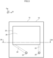
- Fig. 3 is a plan view of the cuvette 15, and Fig. 4 is a cross-sectional view as seen from the direction of the 3A-3A line in Fig. 3 .
- a detailed description of the same components as those in the control cuvette 10 in the cuvette 15 is omitted by giving the same symbols.
- the cuvette 15 has the same configuration as the control cuvette 10 according to an embodiment of the invention except that the observation pattern P is not applied to the bottom surface 28 of the observation section 26.
- the control cuvette 10 according to an embodiment of the invention can be said to be a cuvette in which the part corresponding to the bottom surface 28 of the cuvette 15 is the observation surface 30, or a cuvette prepared by applying the observation pattern P to the bottom surface 28 of the cuvette 15.
- the liquid sample 50 containing the formed element 52 is supplied into the observation section 26 of the cuvette 15, and an image of the formed element 52 contained in the liquid sample 50 in the observation section 26 is captured by the imaging device 60.
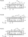
- Fig. 5A to Fig 5C are diagrams illustrating a process in which the liquid sample 50 is supplied to the observation section 26 of the cuvette 15 to prepare for the observation.
- the liquid sample 50 containing the formed element 52, is supplied from the inlet 24 to the cuvette 15, to fill the observation section 26 with the liquid sample 50.
- the liquid sample 50 may be any type of liquid, and examples of the liquid sample 50 include liquids derived from a living body, such as urine or blood of a human.
- the cuvette 15 is subjected to centrifugation treatment using a rotation axis positioned above the cuvette 15.
- the centrifugal force in the observation section 26 causes the formed element 52 contained in the liquid sample 50 to precipitate to the bottom surface 28 of the observation section 26 as illustrated in Fig. 5C .
- the time and the rotation speed of the centrifugation of the cuvette 15 are appropriately determined in accordance with the amount and/or the type of the liquid sample 50 to be observed, the type of the formed element 52, and the like.
- Fig. 6 is a diagram illustrating a process in which the cuvette 15 is mounted on the mounting table 64, and in which the formed element 52 is observed by the imaging device 60 while light is radiated from the light source 62.
- the formed element 52 is positioned within the depth of focus F of the imaging device 60 in a state in which the formed element 52 is precipitated in the bottom portion of the observation section 26.
- the imaging device 60 is capable of capturing an image of the shape of the formed element 52 positioned in the bottom portion of the observation section 26.
- the shape of the formed element 52 whose image has been captured by the imaging device 60 is, for example, converted into electronic data.
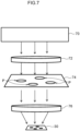
- Fig. 7 is a diagram illustrating a procedure for forming the observation pattern P representing the shape of the formed element 52, on the observation surface 30 using a photolithography apparatus.
- the photolithography apparatus includes an irradiation device 70 for generating light; a condenser lens 72 for condensing the light emitted from the irradiation device 70, a photomask 74 for blocking part of the light that has transmitted through the condenser lens 72, and a projector lens 76 for projecting the light that has transmitted through the photomask 74, to the observation surface 30.
- the observation pattern P representing the shape of the formed element 52 in the liquid sample 50, whose image has been captured in Fig. 6 , is printed using a light-blocking ink based, on the electronic data mentioned above.
- a light-blocking ink is applied to the part excluding the part corresponding to the observation pattern P.
- the type of the light-blocking ink is not limited as long as the ink blocks light emitted from the irradiation device 70.
- the observation surface 30 has a photosetting resin applied thereto which cures in reaction to light emitted from the irradiation device 70.
- the curing of the photosetting resin occurs only in the part irradiated with the light emitted from the irradiation device 70.
- the observation surface 30 is washed.
- the photosetting resin remains only on the part corresponding to the observation pattern P while the resin on the other part is removed. This results in transfer of the observation pattern P representing the shape of the formed element 52 to the observation surface 30.
- the amount of light that passes from the back side to the front side of the observation surface 30 through the part on which the photosetting resin remains is smaller than the amount of light that passes from the back side to the front side of the observation surface 30 through the part from which the photosetting resin has been removed.
- the amount of the light-blocking ink applied may be set in accordance with the tone of the shape obtained by the imaging of the formed element 52, if appropriate.
- control cuvette 10 has the pattern representing the shape of the formed element 52, formed on the observation surface 30.
- a photodegradable resin may be provided instead of the photosetting resin applied to the observation surface 30 in the above description.
- the photodegradable resin is degraded, and hence removed, only in the part exposed to the light through the photomask 74.
- a film on which a pattern representing the shape of the formed element 52 is formed may be attached to the observation surface 30 such that the observation pattern P representing the shape of the formed element 52 can be observed when the control cuvette 10 is examined by microscopy.
- an arbitrary number of the observation pattern P representing the shape of an arbitrary formed element 52 can be transferred onto the observation surface 30 of the control cuvette 10.
- the shape of the formed element 52 whose image is captured using the cuvette 15 shown in Fig. 6 is captured as the observation pattern P.
- control cuvette 10 As an example of the use of the control cuvette 10 according to an embodiment of the invention, a procedure for a case in which the control cuvette 10 according to an embodiment of the invention is used for accuracy control of a measuring apparatus for examining a formed element 52 in a liquid sample 50 is described below.
- an examiner selects a control cuvette 10 to which an observation pattern P of the formed element 52 assumed to be contained in the liquid sample 50 is applied.
- the examiner captures an image of the observation pattern P of the formed element 52 provided in the control cuvette 10, using a measuring apparatus. Thereafter, the examiner confirms whether the observation pattern P included in the captured image data of the control cuvette 10 is recognized by the measuring apparatus as the formed element 52 in the liquid sample 50.
- the examiner can judge that the sensitivity of the measuring apparatus for measuring the formed element 52 in the liquid sample 50 supplied to the cuvette 15 has changed.
- the examiner when the examiner has judged that the sensitivity of the measuring apparatus for examining the formed element 52 in the liquid sample 50 by microscopy has changed, the examiner can carry out a process such as adjustment of the measurement sensitivity of the measuring apparatus. On the other hand, when the sensitivity has been judged not to have changed, the examiner can judge that the adjustment of the measuring apparatus has been completed.
- the examiner captures again an image of the observation pattern P of the formed element 52 applied to the control cuvette 10, and repeats the adjustment of the measuring apparatus such that the measuring apparatus recognizes the observation pattern P included in the captured image data of the control cuvette 10 as the pattern of the formed element 52 in the liquid sample 50.
- the examiner supplies the liquid sample 50 into the cuvette 15, and carries out measurement of the formed element 52 contained in the liquid sample 50 in the cuvette 15, using the measuring apparatus whose adjustment has been completed.
- the examiner uses the control cuvette 10 according to an embodiment of the invention for the purposes of confirmation of the sensitivity and adjustment of the sensitivity for the measurement of the formed element 52 in the liquid sample 50 by the measuring apparatus. It is not necessary for the control cuvette 10 in the above description to be a single cuvette. Depending on the type and the concentration of the formed element 52 contained in the liquid sample 50 to be examined, a plurality of control cuvettes 10 may be provided and selected, if appropriate.
- the described control cuvette 10 is a control cuvette 10 used for measurement accuracy control in a measuring apparatus for observing a formed element 52 contained in a liquid sample 50 after precipitating the formed element 52 to a bottom surface 28 of a cuvette 15, the control cuvette 10 having the same shape as the cuvette 15, and having an observation pattern P representing the shape of the formed element 52 contained in the liquid sample 50, the observation pattern P being applied to an observation surface 30 corresponding to the bottom surface 28 of the cuvette 15.
- control cuvette 10 since the observation pattern P representing the shape of the formed element 52 contained in the liquid sample 50 is applied to the observation surface 30 observed by the measuring apparatus, capturing an image of the observation pattern P of the control cuvette 10 enables acquisition of image data that are similar to those in a case in which an image of the formed element 52 is captured using the cuvette 15.
- the control cuvette 10 can be used for the control of the measurement accuracy of the measuring apparatus for capturing an image of the formed element 52 after precipitating the formed element 52 to the bottom surface of the cuvette 15.
- a control cuvette 10 to which the pattern of the formed element 52 contained in the liquid sample 50 is applied a control cuvette 10 to which the pattern of a desired type of formed element 52 is applied in a desired number can be arbitrarily selected and used for the accuracy control.
- the examiner may provide control cuvettes 10 to which an observation pattern P representing the shape of each formed element 52 to be observed is applied. Thereby, the cost required for the examination can be reduced.
- the cuvette 10 can be repeatedly used for the control of the measurement accuracy even when a rare formed element 52 is to be measured.
- the control of the measurement accuracy in the measurement of the rare formed element 52 is possible by providing a control cuvette 10 to which an observation pattern P representing the shape of the formed element 52 to be measured is applied.
- control cuvette 10 can be easily stored since the control cuvette 10 itself hardly shows deterioration. In other words, the cost required for the examination can be reduced relative to cases in which the cuvette 15 and the control substance are used in the control of the measurement accuracy for the formed element 52.
- an observation pattern P representing the shape of the formed element 52, formed based on image data obtained by capturing an image of the liquid sample 50 containing the formed element 52 using the cuvette 15, is applied, and the observation surface 30 of the control cuvette 10 corresponds to the bottom surface 28 of the cuvette 15.
- the density of the observation pattern P applied to the observation surface 30 of the control cuvette 10 corresponds to the density of the formed element whose image is captured from the liquid sample 50. Therefore, by using the control cuvette 10, the measurement accuracy of the measuring apparatus can be judged in terms of the shape and the density.
- an examiner who is less experienced in the identification of the type and the number of a formed element based on the observation of the size and the shape of the formed element can use the control cuvette 10 as a specimen showing the shape of the formed element 52 observed using the cuvette 15, or as a training sample for the examination of the formed element.
- observation pattern P representing the shape of a formed element 52 contained in urine or blood as the liquid sample 50 is applied to the observation surface 30.
- the cuvette since the observation pattern P of the formed element 52 contained in urine or blood is applied thereto, the cuvette can also be used for accuracy control of the liquid sample 50 derived from a living body.
- an effect similar to that of the control cuvette 10 according to an embodiment of the invention can be obtained also in a case in which the examination by microscopy is carried out using, as the device for the examination by microscopy, a slide glass rather than the cuvette 15, by forming the observation pattern P representing the shape of the formed element 52 on an observation section of the slide glass similarly to the case of the control cuvette 10 described above.
- the invention is applicable to measurement accuracy control in a measuring apparatus for observing a formed element contained in a liquid sample after precipitating the formed element to a bottom surface of a cuvette.
Landscapes
- Health & Medical Sciences (AREA)
- Physics & Mathematics (AREA)
- Life Sciences & Earth Sciences (AREA)
- Chemical & Material Sciences (AREA)
- Immunology (AREA)
- Pathology (AREA)
- General Physics & Mathematics (AREA)
- General Health & Medical Sciences (AREA)
- Analytical Chemistry (AREA)
- Biochemistry (AREA)
- Engineering & Computer Science (AREA)
- Biomedical Technology (AREA)
- Biophysics (AREA)
- Spectroscopy & Molecular Physics (AREA)
- Theoretical Computer Science (AREA)
- Optics & Photonics (AREA)
- Mathematical Physics (AREA)
- Hematology (AREA)
- Molecular Biology (AREA)
- Urology & Nephrology (AREA)
- Food Science & Technology (AREA)
- Medicinal Chemistry (AREA)
- Optical Measuring Cells (AREA)
- Investigating Or Analysing Biological Materials (AREA)
Applications Claiming Priority (1)
| Application Number | Priority Date | Filing Date | Title |
|---|---|---|---|
| JP2022062652A JP7798657B2 (ja) | 2022-04-04 | 2022-04-04 | コントロールキュベット |
Publications (1)
| Publication Number | Publication Date |
|---|---|
| EP4257952A1 true EP4257952A1 (de) | 2023-10-11 |
Family
ID=85800776
Family Applications (1)
| Application Number | Title | Priority Date | Filing Date |
|---|---|---|---|
| EP23165983.0A Pending EP4257952A1 (de) | 2022-04-04 | 2023-03-31 | Kontrollküvette |
Country Status (4)
| Country | Link |
|---|---|
| US (1) | US12517038B2 (de) |
| EP (1) | EP4257952A1 (de) |
| JP (1) | JP7798657B2 (de) |
| CN (1) | CN116893261A (de) |
Citations (8)
| Publication number | Priority date | Publication date | Assignee | Title |
|---|---|---|---|---|
| DE2343149A1 (de) * | 1972-08-30 | 1974-03-14 | Coulter Electronics | Haematokrit-roehrchen-halte- und -messvorrichtung |
| EP0107029A1 (de) * | 1982-09-30 | 1984-05-02 | Miles Laboratories, Inc. | Kontrolleinrichtung und Verfahren zu ihrer Herstellung |
| CN1083590A (zh) * | 1992-08-22 | 1994-03-09 | 湖南省卫生防疫站 | 水质检验方法及设备 |
| DE102008007739A1 (de) * | 2008-02-05 | 2009-08-06 | Fraunhofer-Gesellschaft zur Förderung der angewandten Forschung e.V. | Referenzpräparat für eine Untersuchungsmethode unter Verwendung eines bildgebenden Erfassungs- und Auswertungsverfahrens |
| WO2019165119A1 (en) * | 2018-02-21 | 2019-08-29 | Nexcelom Bioscience Llc | System and method for cell imaging, analysis and measurement |
| CN111829962A (zh) * | 2020-06-28 | 2020-10-27 | 中国科学院苏州生物医学工程技术研究所 | 血浆乳糜程度检测方法及系统 |
| JP2020531852A (ja) | 2017-08-28 | 2020-11-05 | シーメンス・ヘルスケア・ダイアグノスティックス・インコーポレーテッドSiemens Healthcare Diagnostics Inc. | 顕微鏡による尿沈査分析装置で使用する精度管理物質及びその使用方法 |
| KR20210002637A (ko) * | 2018-04-24 | 2021-01-08 | 엔티아 리미티드 | 헤모글로빈 농도를 결정하기 위한 방법 및 장치 |
Family Cites Families (10)
| Publication number | Priority date | Publication date | Assignee | Title |
|---|---|---|---|---|
| US4197088A (en) * | 1977-09-23 | 1980-04-08 | Akro-Medic Engineering, Inc. | Method for qualitative and quantitative determination of immunological reactions |
| US4178345A (en) * | 1978-02-08 | 1979-12-11 | Abbott Laboratories | Cuvette cartridge |
| JPS5933856B2 (ja) * | 1979-10-09 | 1984-08-18 | オリンパス光学工業株式会社 | 凝集反応測定方法およびそれに用いる反応容器 |
| US4666850A (en) * | 1983-10-28 | 1987-05-19 | Becton, Dickinson And Company | Microbial pathogen detecting system and process |
| NO180658C (no) * | 1994-03-10 | 1997-05-21 | Oeystein Fodstad | Fremgangsmåte og anordning for deteksjon av spesifikke målceller i spesialiserte eller blandede cellepopulasjoner og opplösninger som inneholder blandede cellepopulasjoner |
| CA2247115C (en) * | 1996-03-01 | 2008-11-18 | The Regents Of The University Of California | Inhibition of selectin binding |
| JPH11346758A (ja) * | 1998-06-02 | 1999-12-21 | Sugiyama Yukio | 微生物同定試験におけるグラム鑑別用の対照菌株を塗布したスライドグラス |
| US8710179B2 (en) * | 2006-12-14 | 2014-04-29 | Technion Research & Development Foundation Limited | Compositions and methods for concentrating and depleting microorganisms |
| RU2015139001A (ru) * | 2013-03-30 | 2017-05-04 | Клариент Дайагностик Сервисез, Инк. | Предметные стекла микроскопа с контролями качества на них |
| CN107923838B (zh) * | 2015-06-16 | 2021-11-26 | 泰斯科有限公司 | 生物材料测定仪器 |
-
2022
- 2022-04-04 JP JP2022062652A patent/JP7798657B2/ja active Active
-
2023
- 2023-03-30 US US18/128,373 patent/US12517038B2/en active Active
- 2023-03-30 CN CN202310328301.6A patent/CN116893261A/zh active Pending
- 2023-03-31 EP EP23165983.0A patent/EP4257952A1/de active Pending
Patent Citations (8)
| Publication number | Priority date | Publication date | Assignee | Title |
|---|---|---|---|---|
| DE2343149A1 (de) * | 1972-08-30 | 1974-03-14 | Coulter Electronics | Haematokrit-roehrchen-halte- und -messvorrichtung |
| EP0107029A1 (de) * | 1982-09-30 | 1984-05-02 | Miles Laboratories, Inc. | Kontrolleinrichtung und Verfahren zu ihrer Herstellung |
| CN1083590A (zh) * | 1992-08-22 | 1994-03-09 | 湖南省卫生防疫站 | 水质检验方法及设备 |
| DE102008007739A1 (de) * | 2008-02-05 | 2009-08-06 | Fraunhofer-Gesellschaft zur Förderung der angewandten Forschung e.V. | Referenzpräparat für eine Untersuchungsmethode unter Verwendung eines bildgebenden Erfassungs- und Auswertungsverfahrens |
| JP2020531852A (ja) | 2017-08-28 | 2020-11-05 | シーメンス・ヘルスケア・ダイアグノスティックス・インコーポレーテッドSiemens Healthcare Diagnostics Inc. | 顕微鏡による尿沈査分析装置で使用する精度管理物質及びその使用方法 |
| WO2019165119A1 (en) * | 2018-02-21 | 2019-08-29 | Nexcelom Bioscience Llc | System and method for cell imaging, analysis and measurement |
| KR20210002637A (ko) * | 2018-04-24 | 2021-01-08 | 엔티아 리미티드 | 헤모글로빈 농도를 결정하기 위한 방법 및 장치 |
| CN111829962A (zh) * | 2020-06-28 | 2020-10-27 | 中国科学院苏州生物医学工程技术研究所 | 血浆乳糜程度检测方法及系统 |
Also Published As
| Publication number | Publication date |
|---|---|
| CN116893261A (zh) | 2023-10-17 |
| JP2023152542A (ja) | 2023-10-17 |
| US20230314306A1 (en) | 2023-10-05 |
| US12517038B2 (en) | 2026-01-06 |
| JP7798657B2 (ja) | 2026-01-14 |
Similar Documents
| Publication | Publication Date | Title |
|---|---|---|
| RU2399092C2 (ru) | Способ обеспечения качества носителя образца | |
| AU2006221130B2 (en) | A method, device and system for volumetric enumeration of white blood cells. | |
| CN102460115B (zh) | 流式粒子图像分析方法和装置 | |
| JP7214729B2 (ja) | 光学測定用試料収容器 | |
| JP3129015B2 (ja) | 染色された粒子の検査方法及びその装置 | |
| JP5461556B2 (ja) | 尿残渣分析用多層スライド | |
| KR101099333B1 (ko) | 측정 장치, 방법 및 컴퓨터 프로그램 | |
| JP4405600B2 (ja) | 凝集反応を分析するためのイメージング装置を校正するための方法及び装置 | |
| EP0110610A2 (de) | Vorrichtung zum Abgeben von Flüssigkeiten und zum Registrieren von Reaktionen | |
| JPWO2008007725A1 (ja) | 分析装置及びその利用 | |
| JP7086868B2 (ja) | 画像に基づく検体分析 | |
| JP5078920B2 (ja) | 液面検出装置及び方法 | |
| SE531041C2 (sv) | Räkning av trombocyter | |
| US5699794A (en) | Apparatus for automated urine sediment sample handling | |
| EP4257952A1 (de) | Kontrollküvette | |
| CN101821599B (zh) | 用于制备分析板的细胞密度自动调节方法和设备 | |
| TWI755755B (zh) | 用於測試生物樣本的裝置 | |
| JP2006138654A (ja) | 有形成分分析装置および有形成分分析方法 | |
| TWI274148B (en) | Method and system for analyzing test devices | |
| WO2013010999A9 (en) | Method and system for analyzing a liquid cell sample by digital holographic microscopy | |
| CN114324924A (zh) | 支持液体样本的测量 | |
| CN114514419A (zh) | 体液分析装置及利用该装置的体液分析方法 | |
| JP2807989B2 (ja) | 細胞分析方法及び装置 | |
| JP2002544560A (ja) | 機械的にサンプルに振動を加えながら固体粒子サスペンションの抽出されたサンプルを測定するための高い分解能のビデオ顕微鏡 | |
| CN118037625A (zh) | 一种图像检测方法、样本分析仪和粪便检测装置 |
Legal Events
| Date | Code | Title | Description |
|---|---|---|---|
| PUAI | Public reference made under article 153(3) epc to a published international application that has entered the european phase |
Free format text: ORIGINAL CODE: 0009012 |
|
| STAA | Information on the status of an ep patent application or granted ep patent |
Free format text: STATUS: THE APPLICATION HAS BEEN PUBLISHED |
|
| AK | Designated contracting states |
Kind code of ref document: A1 Designated state(s): AL AT BE BG CH CY CZ DE DK EE ES FI FR GB GR HR HU IE IS IT LI LT LU LV MC ME MK MT NL NO PL PT RO RS SE SI SK SM TR |
|
| STAA | Information on the status of an ep patent application or granted ep patent |
Free format text: STATUS: REQUEST FOR EXAMINATION WAS MADE |
|
| 17P | Request for examination filed |
Effective date: 20240409 |
|
| RBV | Designated contracting states (corrected) |
Designated state(s): AL AT BE BG CH CY CZ DE DK EE ES FI FR GB GR HR HU IE IS IT LI LT LU LV MC ME MK MT NL NO PL PT RO RS SE SI SK SM TR |
|
| STAA | Information on the status of an ep patent application or granted ep patent |
Free format text: STATUS: EXAMINATION IS IN PROGRESS |
|
| RIC1 | Information provided on ipc code assigned before grant |
Ipc: G01N 33/50 20060101ALI20250219BHEP Ipc: A61B 5/00 20060101ALI20250219BHEP Ipc: G01N 21/27 20060101ALI20250219BHEP Ipc: G01N 21/07 20060101AFI20250219BHEP |
|
| 17Q | First examination report despatched |
Effective date: 20250311 |