EP4257936B1 - Unité d'accueil pour relier un récipient pour un milieu liquide à une dérivation - Google Patents
Unité d'accueil pour relier un récipient pour un milieu liquide à une dérivation Download PDFInfo
- Publication number
- EP4257936B1 EP4257936B1 EP23165566.3A EP23165566A EP4257936B1 EP 4257936 B1 EP4257936 B1 EP 4257936B1 EP 23165566 A EP23165566 A EP 23165566A EP 4257936 B1 EP4257936 B1 EP 4257936B1
- Authority
- EP
- European Patent Office
- Prior art keywords
- container
- docking unit
- insert
- unit
- sensor
- Prior art date
- Legal status (The legal status is an assumption and is not a legal conclusion. Google has not performed a legal analysis and makes no representation as to the accuracy of the status listed.)
- Active
Links
Images


Classifications
-
- B—PERFORMING OPERATIONS; TRANSPORTING
- B67—OPENING, CLOSING OR CLEANING BOTTLES, JARS OR SIMILAR CONTAINERS; LIQUID HANDLING
- B67D—DISPENSING, DELIVERING OR TRANSFERRING LIQUIDS, NOT OTHERWISE PROVIDED FOR
- B67D7/00—Apparatus or devices for transferring liquids from bulk storage containers or reservoirs into vehicles or into portable containers, e.g. for retail sale purposes
- B67D7/02—Apparatus or devices for transferring liquids from bulk storage containers or reservoirs into vehicles or into portable containers, e.g. for retail sale purposes for transferring liquids other than fuel or lubricants
- B67D7/0288—Container connection means
-
- B—PERFORMING OPERATIONS; TRANSPORTING
- B67—OPENING, CLOSING OR CLEANING BOTTLES, JARS OR SIMILAR CONTAINERS; LIQUID HANDLING
- B67D—DISPENSING, DELIVERING OR TRANSFERRING LIQUIDS, NOT OTHERWISE PROVIDED FOR
- B67D7/00—Apparatus or devices for transferring liquids from bulk storage containers or reservoirs into vehicles or into portable containers, e.g. for retail sale purposes
- B67D7/02—Apparatus or devices for transferring liquids from bulk storage containers or reservoirs into vehicles or into portable containers, e.g. for retail sale purposes for transferring liquids other than fuel or lubricants
- B67D7/0277—Apparatus or devices for transferring liquids from bulk storage containers or reservoirs into vehicles or into portable containers, e.g. for retail sale purposes for transferring liquids other than fuel or lubricants using negative pressure
-
- G—PHYSICS
- G01—MEASURING; TESTING
- G01F—MEASURING VOLUME, VOLUME FLOW, MASS FLOW OR LIQUID LEVEL; METERING BY VOLUME
- G01F23/00—Indicating or measuring liquid level or level of fluent solid material, e.g. indicating in terms of volume or indicating by means of an alarm
- G01F23/22—Indicating or measuring liquid level or level of fluent solid material, e.g. indicating in terms of volume or indicating by means of an alarm by measuring physical variables, other than linear dimensions, pressure or weight, dependent on the level to be measured, e.g. by difference of heat transfer of steam or water
- G01F23/28—Indicating or measuring liquid level or level of fluent solid material, e.g. indicating in terms of volume or indicating by means of an alarm by measuring physical variables, other than linear dimensions, pressure or weight, dependent on the level to be measured, e.g. by difference of heat transfer of steam or water by measuring the variations of parameters of electromagnetic or acoustic waves applied directly to the liquid or fluent solid material
- G01F23/284—Electromagnetic waves
-
- A—HUMAN NECESSITIES
- A47—FURNITURE; DOMESTIC ARTICLES OR APPLIANCES; COFFEE MILLS; SPICE MILLS; SUCTION CLEANERS IN GENERAL
- A47L—DOMESTIC WASHING OR CLEANING; SUCTION CLEANERS IN GENERAL
- A47L15/00—Washing or rinsing machines for crockery or tableware
- A47L15/42—Details
- A47L15/44—Devices for adding cleaning agents; Devices for dispensing cleaning agents, rinsing aids or deodorants
- A47L15/4418—Devices for adding cleaning agents; Devices for dispensing cleaning agents, rinsing aids or deodorants in the form of liquids
-
- D—TEXTILES; PAPER
- D06—TREATMENT OF TEXTILES OR THE LIKE; LAUNDERING; FLEXIBLE MATERIALS NOT OTHERWISE PROVIDED FOR
- D06F—LAUNDERING, DRYING, IRONING, PRESSING OR FOLDING TEXTILE ARTICLES
- D06F39/00—Details of washing machines not specific to a single type of machines covered by groups D06F9/00 - D06F27/00
- D06F39/02—Devices for adding soap or other washing agents
- D06F39/022—Devices for adding soap or other washing agents in a liquid state
Definitions
- the invention relates to a docking unit for connecting a container for a liquid medium to a discharge line, preferably a hose, wherein the docking unit can be detachably fastened to an opening of the container so that a liquid medium can flow through the docking unit.
- the invention further relates to an arrangement comprising a docking unit and an insert for a container, a dosing device and a method for attaching a docking unit to a container.
- the writing EP 2 868 622 A1 shows a suction lance with a level sensor at the distal end of the suction pipe.
- the disadvantage is that the level sensor comes into contact with the medium, which exposes it to its potentially corrosive properties. Furthermore, a level sensor in direct contact with the medium becomes contaminated and therefore requires regular cleaning. This requires additional effort.
- the writing WO 2021/239260 A1 shows a level measuring device for use in the technical field of process automation and logistics, which features an optical time-of-flight sensor and a radar time-of-flight sensor.
- the disadvantage of this level measuring device is that it requires an additional step for attaching it to the container, for example, by gluing. Furthermore, the level measuring device requires additional cabling or an additional radio connection.
- a container's top wall is often not parallel to the liquid surface. Especially with plastic containers, the container's top wall may have pronounced curvatures or handles, for example. This makes it difficult to find a suitable location for a level gauge on the container, since the level gauge should essentially be aligned horizontally.
- the invention is intended to remedy the above-mentioned disadvantages.
- the invention aims to create a docking unit with level measurement that is low-maintenance and easy to position.
- the object is achieved by a docking unit according to claim 1, an arrangement according to claim 8, a container according to claim 10, a dosing device according to claim 11 and a method according to claim 14.
- At least one fill level sensor designed as a transit time sensor, in particular a RADAR sensor, is arranged in the docking unit.
- the transit time sensor allows contactless measurement of the tank's fill level. This prevents the sensor from being contaminated by the liquid in the tank, making it particularly low-maintenance.
- the transit time sensor is located in the docking unit, the transit time sensor is integrated with the docking unit's detachable attachment to the container. Additional cabling or the provision of a wireless connection is therefore obsolete.
- “Arranged in the docking unit” can mean that the time-of-flight sensor forms a single unit with the docking unit.
- the time-of-flight sensor can be arranged in or on the housing of the docking unit.
- the docking unit can be reliably positioned in a straight line because it is located in the container opening. Therefore, no additional suitable space for the transit time sensor needs to be found on the container's top wall.
- the time-of-flight sensor is generally designed to send signals, receive a reflected signal and calculate a distance by determining a time difference between the transmission time of the signal and the arrival time of the reflected signal.
- the transit time sensor can be designed to calculate the distance from the liquid surface in the container to the transit time sensor.
- the at least one transit time sensor is arranged outside the container when the docking unit is attached to the container.
- Signals preferably electromagnetic waves, particularly preferably microwaves, can be transmitted from the at least one transit time sensor through a container wall into the interior of the container. Contact of the sensor with the medium is therefore excluded. The transit time sensor therefore does not require regular cleaning.
- the docking unit has at least one lens for the at least one time-of-flight sensor, wherein the signals emitted by the at least one time-of-flight sensor are transmitted through the lens.
- the signals can thus be shaped, preferably focused, by the lens.
- the level measurement with the time-of-flight sensor can be inaccurate, especially since the time-of-flight sensor can no longer adequately distinguish between the echo reflected from the surface of the medium and the echo reflected from the bottom. Therefore, it is difficult to detect an empty container.
- the docking unit has at least one empty level sensor for detecting whether medium or air is present in the fluid channel of the docking unit. This combines a fill level sensor and an empty level sensor in the docking unit, with the sensors advantageously complementing each other.
- the empty level sensor is designed as an optical sensor, whereby the optical sensor detects air on are optically detectable.
- the optical sensor detects air on are optically detectable.
- light can be refracted differently through the air in a distinguishable way, which is detectable.
- the empty level sensor can comprise a float.
- an electronic switch can be actuated by the float.
- the electronic switch in particular a reed switch, can be arranged in an area free of liquid medium.
- the docking unit can have a reader for contactless reading of a data carrier. It is preferably provided that the reader is designed as an RFID reader. This allows data about the container to be read. Furthermore, data can be written into the RFID tag in the container, in particular also regarding the fill level in the container.
- the docking unit has a logic unit, wherein the logic unit is in data communication with the at least one fill level sensor.
- the logic unit can be connected to a data transmission system, preferably a bus system, via a data connection and/or an antenna.
- the logic unit acts as a central point of contact for data from the fill level sensor, the empty level sensor, and/or the reader. Data can be processed and/or forwarded.
- Other units of the dosing device can be integrated into the BUS system, for example a central control unit.
- the docking unit can have a check valve in a fluid channel between a fluid inlet for the intake of medium from the container and a fluid outlet.
- a ball of the check valve can be lifted by a negative pressure in the docking unit, or the check valve can be mechanically pushed open by the docking. This allows the liquid medium to flow into the docking unit.
- the check valve prevents dripping.
- the docking unit can have a liquid outlet, wherein the liquid outlet is communicatively connected to the liquid inlet via a liquid channel.
- a discharge line in particular a hose, can preferably be attached to the liquid outlet.
- the hose can then lead to a pump, by means of which a liquid medium can be conveyed through the hose and through the docking unit from the container toward at least one target device.
- the docking unit may have a liquid inlet for introducing medium into the container, wherein the liquid inlet is arranged at the bottom when the docking unit is attached.
- the docking unit may have at least one fastening projection and/or a counter thread for engagement in a recess or a Container closure threads in or on the container or in or on an insert attached to the container. This allows the docking unit to be attached to the container detachably and without tools.
- the docking unit can be releasably attached to the container by plugging and/or docking it into or onto a sealing point of an insert or the container.
- An arrangement according to the invention comprises a described docking unit and an insert for the container, wherein the insert can be fastened, in particular welded, or detachably fastened, in particular pressed in, screwed in, or fastened by means of a union nut, in an opening of the container.
- Detachable fastening has the advantage that the container is reusable and recyclable after the insert has been removed.
- the insert can be connected, in particular latched, to a locking hook, wherein the locking hook can be placed against the inside of the container.
- the locking hook can press against the inside of the container and thus hold the insert in the opening of the container.
- the locking hook can be an elongated component which can be inserted lengthwise through the opening of the container into the container and can bridge the opening crosswise so that the locking hook can be applied to the inside of the container.
- the insert may have a fastening part for fastening in an opening of the container.
- the fastening part may have a suitable shape or fastening means. It is preferably provided that a data carrier, in particular an RFID tag, is arranged on or in the fastening part.
- the data carrier can be read with a reader, which can be arranged in the docking unit.
- the insert can be provided with a suction tube, wherein the suction tube is connected to the fastening part and extends into the interior of the container.
- the suction tube By means of the suction tube, liquid medium can be sucked into the docking unit and further toward a target device.
- a docking unit is detachably attached to a container according to the invention. It is preferably provided that the at least one docking unit is arranged on the top side of the container.
- an insert is fastened in the container, in particular in the opening of the container.
- a dosing device comprises at least one container with a docking unit and insert, wherein the liquid medium can be conveyed by at least one pump from the at least one container through the docking unit toward at least one target device, in particular at least one washing machine or at least one dishwasher.
- the at least one pump is arranged downstream of the docking unit in the conveying path.
- the at least one pump can also be arranged in the docking unit.
- the docking unit in particular the logic unit of the docking unit, is in data communication with a central control unit for controlling the dosing device.
- the central control unit can also be in data communication with, among other things, the pump and the target device.
- At least two containers with a docking unit and/or insert and at least two pumps are provided, with one pump being provided for each container.
- the liquid medium can be conveyed by means of the pumps into a dispensing manifold, preferably wherein the liquid medium can be conveyed from the dispensing manifold via a rinsing medium, in particular water, to at least one target device.
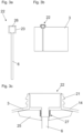
- the Fig. 1a shows a dosing device 32 for dosing a liquid medium 9, which is located in a container 3.
- the liquid medium 9 can be sucked in by means of a pump 1 through a docking unit 2, which is detachably attached to an opening of the container 3.
- the liquid medium 9 can be conveyed by the pump 1 in the direction of a target device, in particular a washing machine or a dishwasher (arrows in the Figures 1a and 1b ). It may be provided that the liquid medium 9 is not conveyed directly to the target device by means of the pump. Instead, a dispensing distributor may be provided upstream of the flushing device, in which various media 9 are mixed and conveyed further to a target device by means of a flushing medium.
- Both the pump 1 and the docking unit 2 are connected to a central control unit 4 via a data line.
- the central control unit 4 can control the entire dosing device 32 and serves as the central processing unit for the dosing device 32.
- the central control unit 4 is in data communication with the pump 1 and the docking unit 2 via data lines 12.
- the docking unit 2 has a time-of-flight sensor 5, in particular a radar sensor.
- the time-of-flight sensor 5 can emit signals 13, which are reflected, among other things, by the surface of the liquid medium 9 located in the container 3. The reflected echo can be received by the time-of-flight sensor 5.
- the fill level 7 of the container 3 can be determined. In particular, continuous fill level measurement is possible.
- a volume difference between the first and second fill levels can be used as a reference volume for calibrating pump 1.
- the calibration calculation takes place in the central control unit 4.
- the transit time sensor 5 can measure any fill level 7, the reference volume can be freely selected. This enables virtually continuous level measurement and also virtually continuous calibration.
- a logic unit 11 is also arranged in the docking unit 2, which, among other things, forwards the data from the runtime sensor 5.
- the Fig. 1b shows a dosing device 32 with several containers 3, which can contain different liquid media 9.
- a separate docking unit 2 with a transit time sensor 5 is arranged on each container 3, with each docking unit 2 being communicatively connected to a pump 1 via a discharge line 10.
- All docking units 2 and all pumps 1 are connected to a central control unit 4 via data lines 12.
- the data lines 12 can also be designed wirelessly via radio.
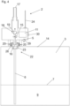
- the Fig. 2 shows an embodiment of a docking unit 2 in a schematic sectional view.
- a liquid outlet 17 is provided on the top side of the docking unit 2, which is suitable for connecting a hose as a drain line 10.
- the sectional view also shows the liquid inlet 16, through which a liquid medium 9 can enter the docking unit 2.
- the liquid inlet 16 is formed on an extension on the underside of the docking unit 2, so that the liquid inlet can be inserted into an insert 22 and/or a container 3.
- a fluid channel 31 connects the fluid inlet 16 to the fluid outlet 17.
- a check valve 18 is arranged in the fluid channel 31.
- the check valve 18 has a sealing ball 19.
- the ball 19 can be sealingly pressed against a tapered part of the fluid channel 31 by means of a spring (not shown) or by gravity. If a negative pressure is applied by the pump 1, the ball 19 is lifted and fluid can flow through the fluid channel 31.
- the check valve 18 can be mechanically pressed open during docking.
- time-of-flight sensor 5 which is arranged on the underside of the docking unit 2.
- the time-of-flight sensor 5 can thus transmit signals 13 through the container wall into the interior of the container 3.
- a lens 29 can be arranged in the signal path, although the lens 29 is not absolutely necessary for the function.
- an empty level sensor 15 which can measure the empty level in the container 3.
- the empty level sensor 15 can detect air in the sucked-in liquid medium 9. The air enters the liquid medium when the container 3 is almost empty.
- the empty level sensor 15 is designed as an optical sensor.
- a translucent section of the liquid channel 31 is illuminated by light from one side using a light source.
- a sensor capable of detecting the light is mounted on the opposite side of the liquid channel. The air in the liquid medium changes the refraction behavior of the light, allowing the presence of air to be detected.
- a logic unit 11 is also schematically shown in the docking unit 2. This unit is in data communication with the runtime sensor 5 and the empty level sensor 15. The logic unit 11 can also be in data communication with a reader for reading RFID data from an RFID tag located in the container 3 or in the insert 22, although the reader is not shown.
- the data can be forwarded to an antenna 24 for wireless data transmission and/or a data port 30 for connecting a cable for wired data transmission.
- the docking unit can communicate with other units via these interfaces.
- the docking unit 2 can be connected to a central control unit 4 in this way.
- a counter thread 20 is provided on the underside of the docking unit.
- the counter thread 20 can be designed to engage a container closure thread 21.
- the Fig. 3a shows an insert 22 in a schematic sectional view.
- the Fig. 3b shows an insert 22 detachably attached to a container 3.
- the insert 22 has a suction tube 6 and a fastening part 23. With the fastening part 23, the insert 22 can be releasably fastened in a container opening, preferably by pressing it in. Because the insert 22 is releasably fastened in the container 3, the container 3 can be recycled or reused separately from the insert 22 after use.
- a seal 26 is also arranged on the fastening part 23, which can seal the insert 22 against an inserted docking unit 2.
- the suction pipe 6 which is preferably made of a softer material than the fastening part 23, the liquid medium 9 can be sucked out of the container 3.
- the insert 22 is inserted into the container opening and is preferably pressed in there.
- a data carrier in particular an RFID tag, can be arranged on the insert 22, which can be read by means of a reading device arranged on the docking unit 2.
- the Fig. 3c shows an alternative embodiment of an insert 22.
- the insert 33 can be connected to a locking hook 25.
- the locking hook 25 is an additional component that can be applied to the inside of the container 3.
- the locking hook 25 can be designed such that it can be inserted lengthwise through the container opening into the container 3 and can bridge the container opening transversely. The locking hook 25 can thus press against the inside of the container 3 and hold the insert 22 in the opening of the container 3.
- connection between the insert 22 and the locking hook 25 is preferably achieved by locking with a locking device 27, but other connections are also possible.
- a locking device 27 can have several locking teeth.
- the Fig. 4 shows a container 3 with an insert 22, which is fastened in the container opening, and a docking unit 2, which is detachably fastened in the insert 22 and on the container 3.
- the docking unit 2 can be releasably fastened to the container closure thread 21 of the container 3 by rotation or by hooking by means of a counter thread 20 arranged on the docking unit 2.
- the liquid inlet 16 is thereby brought into communicative connection with the interior of the insert 22 and the suction tube 6, so that liquid medium 9 can be sucked from the container 3 into the docking unit 2.
- the transit time sensor 5 When the docking unit 2 is attached, the transit time sensor 5 is directed downward toward the container 3 to measure the fill level.
- the signals 13 of the transit time sensor 5 are transmitted through the upper container wall 14 into the interior of the container 3.
- the echo reflected by the liquid medium 9, in particular the surface of the liquid medium 9 at a certain fill level 7, also passes through the container wall 14 and is detected by the transit time sensor 5.
- the fill level 7 in the container 3 can be determined. At very low fill levels 7, the runtime sensor 5 is no longer reliable. Therefore, the additional empty level sensor 15 can be used to detect whether air is being sucked in through the intake manifold 6.
Landscapes
- Physics & Mathematics (AREA)
- Electromagnetism (AREA)
- Thermal Sciences (AREA)
- Fluid Mechanics (AREA)
- General Physics & Mathematics (AREA)
- Engineering & Computer Science (AREA)
- Mechanical Engineering (AREA)
- Details Of Rigid Or Semi-Rigid Containers (AREA)
- Measurement Of Levels Of Liquids Or Fluent Solid Materials (AREA)
Claims (14)
- Unité de couplage (2) pour raccorder un récipient (3) pour un milieu liquide (9) à une conduite d'évacuation (10), de préférence un tuyau flexible, dans laquelle l'unité de couplage (2) peut être fixée de manière amovible à une ouverture du récipient (3) si bien que le milieu liquide (9) peut s'écouler à travers l'unité de couplage (2), dans laquelle au moins un capteur de niveau de remplissage réalisé comme capteur de temps de propagation (5), en particulier capteur RADAR, destiné à mesurer le niveau de remplissage (7) dans le récipient (3) est disposé dans l'unité de couplage (2), caractérisée en ce que l'au moins un capteur de temps de propagation (5) est disposé dans l'état fixé sur le récipient (3) de l'unité de couplage (2) à l'extérieur du récipient (3) et/ou que des signaux (13), de préférence des ondes électromagnétiques, de manière particulièrement préférée des micro-ondes, peuvent être envoyés par l'au moins un capteur de niveau de remplissage à travers une paroi de récipient (14) à l'intérieur du récipient (3).
- Unité de couplage (2) selon l'une quelconque des revendications précédentes, dans laquelle l'unité de couplage (2) présente au moins une lentille (29) pour l'au moins un capteur de temps de propagation (5), dans laquelle les signaux (13) émis par l'au moins un capteur de temps de propagation (5) sont envoyés à travers la lentille (29), de préférence dans laquelle les signaux (13) peuvent être focalisés par la lentille (29).
- Unité de couplage (2) selon l'une quelconque des revendications précédentes, dans laquelle l'unité de couplage (2) présente au moins un capteur de niveau vide (15) pour détecter si du milieu ou de l'air se trouve dans le canal de liquide (31) de l'unité de couplage, de préférence dans laquelle- le capteur de niveau vide (15) est formé en tant que capteur optique, dans laquelle l'air peut être détecté par voie optique au moyen du capteur optique, et/ou- le capteur de niveau vide (15) comprend un flotteur, de manière particulièrement préférée, dans laquelle un commutateur électronique peut être actionné par le flotteur en fonction de la position du flotteur.
- Unité de couplage (2) selon l'une quelconque des revendications précédentes, dans laquelle l'unité de couplage (2)- présente un lecteur pour la lecture sans contact d'un support de données, de préférence dans laquelle le lecteur est formé comme un lecteur RFID, et/ou- présente une unité logique (11), dans laquelle l'unité logique (11) est en liaison de données avec l'au moins un capteur de temps de propagation (5), de manière préférée dans laquelle l'unité logique (11) peut être raccordée à un système de transmission de données, de préférence un système BUS, par l'intermédiaire d'un port de données (30) et/ou d'une antenne (24).
- Unité de couplage (2) selon l'une quelconque des revendications précédentes, dans laquelle l'unité de couplage (2) présente un clapet antiretour (18) dans un canal de liquide (31) entre une entrée de liquide (16) pour l'admission de milieu provenant du récipient (3) et une sortie de liquide (17), de préférence dans laquelle une bille (19) du clapet antiretour (18) peut être soulevée par une dépression dans l'unité de couplage (2) ou le clapet antiretour (18) peut être poussé mécaniquement par le couplage et donc le milieu liquide (9) peut s'écouler dans l'unité de couplage (2).
- Unité de couplage (2) selon l'une quelconque des revendications précédentes, dans laquelle l'unité de couplage (2) présente une sortie de liquide (17), dans laquelle la sortie de liquide (17) est en communication avec l'entrée de liquide (16) par l'intermédiaire d'un canal de liquide (31), de préférence dans laquelle une conduite d'évacuation (10), en particulier un tuyau flexible, peut être fixée sur la sortie de liquide (17) et/ou dans laquelle l'unité de couplage présente une entrée de liquide (16) pour l'entrée de milieu dans le récipient (3), dans laquelle l'entrée de liquide est disposée en bas dans l'état fixé de l'unité de couplage (2).
- Unité de couplage (2) selon l'une quelconque des revendications précédentes, dans laquelle l'unité de couplage (2) présente au moins une saillie de fixation et/ou un contre-filetage (20) pour venir en prise avec un guide ou un filetage de fermeture de récipient (21) dans le récipient (3) ou dans un insert (22) fixé dans le récipient (3).
- Ensemble comprenant une unité de couplage (2) selon l'une quelconque des revendications précédentes et un insert (22) pour le récipient (3), dans lequel, dans une ouverture du récipient (3), l'insert (22)- peut être fixé, en particulier soudé, et/ou- peut être fixé de manière amovible, en particulier peut être compressé, vissé ou peut être fixé au moyen d'un écrou-raccord, et/ou- peut être relié, en particulier par enclenchement, à un crochet d'enclenchement (25), dans lequel le crochet d'enclenchement (25) peut être posé sur la face intérieure du récipient (3).
- Ensemble selon la revendication précédente, dans lequel l'insert (22) présente une pièce de fixation (23) pour la fixation dans une ouverture du récipient (3), de préférence- dans lequel un support de données, en particulier une étiquette RFID, est disposé sur ou dans la pièce de fixation (23), et/ou- dans lequel l'insert (22) présente un tube d'aspiration (6), dans lequel le tube d'aspiration (6) est relié à la pièce de fixation (23) et dépasse à l'intérieur du récipient (3).
- Récipient (3), sur lequel une unité de couplage (2) est fixée de manière amovible selon l'une quelconque des revendications 1 à 7, de préférence dans lequel- l'au moins une unité de couplage (2) est disposée sur la face supérieure du récipient (3), et/ou- au moins un insert (22) selon la revendication 8 ou 9 est fixé dans le récipient (3).
- Dispositif de dosage (32) avec au moins un récipient (3) selon la revendication précédente, dans lequel le milieu liquide (9) peut être refoulé avec au moins une pompe (1) à partir de l'au moins un récipient (3) à travers l'unité de couplage (2) en direction d'au moins un appareil cible, en particulier au moins un lave-linge ou au moins un lave-vaisselle, de préférence dans lequel l'au moins une pompe (1) est disposée après l'unité de couplage (2).
- Dispositif de dosage (32) selon la revendication précédente, dans lequel l'unité de couplage (2), en particulier l'unité logique (11) de l'unité de couplage (2), est en liaison de données avec une unité de commande centrale (4) pour commander le dispositif de dosage (32).
- Dispositif de dosage (32) selon la revendication 11 ou 12, dans lequel au moins deux récipients (3) selon la revendication 10 et au moins deux pompes (1) sont prévus et une pompe (1) est prévue respectivement par récipient (3), de préférence dans lequel le milieu liquide (9) peut être refoulé au moyen des pompes (1) dans un distributeur d'injection, de manière particulièrement préférée dans lequel le milieu liquide (9) peut être refoulé du distributeur d'injection par l'intermédiaire un milieu de rinçage, en particulier de l'eau, jusqu'à au moins un appareil cible.
- Procédé d'installation d'une unité de couplage (2) sur un récipient (3) avec les étapes de procédé suivantes :- de compression d'un insert (22) et/ou de soudage d'un insert (22) et/ou de fixation d'un insert (22) au moyen d'un écrou-raccord et/ou de fixation d'un insert (22) sur un crochet d'enclenchement (25) pouvant être placé sur la paroi intérieure du récipient (3), en particulier d'un insert (22) selon la revendication 8 ou 9, dans l'ouverture du récipient (3),- de fixation amovible de l'unité de couplage (2) selon l'une quelconque des revendications 1 à 7 sur l'insert (22), de préférence dans lequel l'unité de couplage (2) peut être fixée de manière amovible par rotation ou par accrochage sur un filetage de fermeture de récipient (21) du récipient (3) et/ou par enfichage et/ou couplage dans ou sur un point d'étanchéité.
Applications Claiming Priority (1)
| Application Number | Priority Date | Filing Date | Title |
|---|---|---|---|
| ATA50227/2022A AT526047A1 (de) | 2022-04-07 | 2022-04-07 | Andockeinheit zur Verbindung eines Behälters für ein flüssiges Medium mit einer Ableitung |
Publications (3)
| Publication Number | Publication Date |
|---|---|
| EP4257936A1 EP4257936A1 (fr) | 2023-10-11 |
| EP4257936B1 true EP4257936B1 (fr) | 2025-05-28 |
| EP4257936C0 EP4257936C0 (fr) | 2025-05-28 |
Family
ID=85792499
Family Applications (1)
| Application Number | Title | Priority Date | Filing Date |
|---|---|---|---|
| EP23165566.3A Active EP4257936B1 (fr) | 2022-04-07 | 2023-03-30 | Unité d'accueil pour relier un récipient pour un milieu liquide à une dérivation |
Country Status (3)
| Country | Link |
|---|---|
| EP (1) | EP4257936B1 (fr) |
| AT (1) | AT526047A1 (fr) |
| ES (1) | ES3034770T3 (fr) |
Family Cites Families (12)
| Publication number | Priority date | Publication date | Assignee | Title |
|---|---|---|---|---|
| US5950487A (en) * | 1996-09-20 | 1999-09-14 | Vista Research, Inc. | Gauge for measuring liquid levels |
| WO2002050954A2 (fr) * | 2000-12-21 | 2002-06-27 | Siemens Milltronics Process Instruments Inc. | Antenne cornet a hyperfrequence utilisee avec des systemes de mesure du niveau |
| US6879876B2 (en) * | 2001-06-13 | 2005-04-12 | Advanced Technology Materials, Inc. | Liquid handling system with electronic information storage |
| US7224273B2 (en) * | 2002-05-23 | 2007-05-29 | Forster Ian J | Device and method for identifying a container |
| DE102005049242B4 (de) * | 2005-10-14 | 2008-01-24 | Vega Grieshaber Kg | Parabolantenne mit konischer Streuscheibe für Füllstandradar |
| US9151838B2 (en) * | 2012-11-02 | 2015-10-06 | Magnetrol International, Inc. | Ceramic probe rod support assembly |
| US9291492B2 (en) * | 2013-03-12 | 2016-03-22 | Rosemount Tank Radar Ab | Tank feed through structure for a radar level gauge |
| EP2868622A1 (fr) | 2013-10-30 | 2015-05-06 | Rolitec AG | Dispositif d'extraction |
| WO2020112241A1 (fr) * | 2018-11-30 | 2020-06-04 | Carrier Corporation | Capteur de niveau de réservoir de produit d'extinction d'incendie à piège magnétique |
| DE102019132397A1 (de) * | 2019-11-28 | 2021-06-02 | Vega Grieshaber Kg | Füll-oder Grenzstandsensor, Messanordnung mit einem Füll- oder Grenzsstandsensor und Verfahren zur Befestigung eines Füll- oder Grenzstandsensor an einem Behälter |
| US11142449B2 (en) * | 2020-01-02 | 2021-10-12 | Fuel Automation Station, LLC | Method and system for dispensing fuel using side-diverting fuel outlets |
| WO2021239260A1 (fr) * | 2020-05-29 | 2021-12-02 | Vega Grieshaber Kg | Dispositif de mesure optique de niveau de remplissage |
-
2022
- 2022-04-07 AT ATA50227/2022A patent/AT526047A1/de unknown
-
2023
- 2023-03-30 ES ES23165566T patent/ES3034770T3/es active Active
- 2023-03-30 EP EP23165566.3A patent/EP4257936B1/fr active Active
Also Published As
| Publication number | Publication date |
|---|---|
| EP4257936C0 (fr) | 2025-05-28 |
| EP4257936A1 (fr) | 2023-10-11 |
| AT526047A1 (de) | 2023-10-15 |
| ES3034770T3 (en) | 2025-08-22 |
Similar Documents
| Publication | Publication Date | Title |
|---|---|---|
| EP3746752B1 (fr) | Dispositif de mesure du niveau de remplissage | |
| DE69913424T2 (de) | Inkrementaler Absorptionsabtastung von Flüssigkeit in einer Abgabespitze | |
| EP3296075B1 (fr) | Dispositif de transport d'une matière visqueuse provenant d'un récipient et procédé de fonctionnement du dispositif de transport | |
| EP3054271B1 (fr) | Détecteur de niveau doté d'un capteur de position intégré | |
| DE102009000062A1 (de) | Füllstandsmessvorrichtung und Verfahren zur Füllstandsbestimmung | |
| EP4257936B1 (fr) | Unité d'accueil pour relier un récipient pour un milieu liquide à une dérivation | |
| DE102016123489A1 (de) | Füllstandssensor | |
| EP1971547B1 (fr) | Procede et dispositif de prelevement d' un fluide dans une cuve | |
| EP1456612B1 (fr) | Procede permettant de determiner et / ou de surveiller une grandeur de processus physique ou chimique | |
| EP4158289A1 (fr) | Dispositif de mesure optique de niveau de remplissage | |
| EP4257937A1 (fr) | Dispositif de dosage pour doser un milieu liquide pour au moins un appareil cible comprenant un système d'étalonnage d'au moins une pompe | |
| EP4390337A1 (fr) | Procédé d'étalonnage d'un appareil de transport et procédé de dosage et dispositif de dosage | |
| AT526064B1 (de) | Verfahren zum Kalibrieren eines Fördergeräts und Dosiervorrichtung | |
| EP1943930B1 (fr) | Machine à boissons | |
| EP3768610A1 (fr) | Conteneur et son procédé de fonctionnement | |
| EP3382352B1 (fr) | Débitmètre à roue ovale, procédé de mesure d'un flux et système de dosage | |
| EP1832878A1 (fr) | Récipient avec un transpondeur assuré contre les faux | |
| WO2019096466A1 (fr) | Procédé de création d'une courbe de suppression pour appareil de mesure de niveau de remplissage | |
| CN120112324A (zh) | 使用成像技术的改进的药物制备方法和系统 | |
| DE102008007970A1 (de) | Verfahren und Vorrichtung zur Dosierung einer Flüssigkeit in einem Flüssigkeitsbehälter | |
| DE102006026025A1 (de) | Leitungselement für flüssige Lebensmittel und Anordnung mit einem Leitungselement | |
| DE102020202951A1 (de) | Dosiervorrichtung und Verfahren zum Betreiben einer Dosiervorrichtung | |
| DE4440883C2 (de) | Vorrichtung zur Überwachung des mittels einer Förderpumpe durchgeführten Einfüllvorganges abrasiver, stark verschmutzter Flüssigkeiten, insbesondere Altöl an Tankfahrzeugen | |
| EP3232168A1 (fr) | Détermination du niveau de remplissage d'un milieu | |
| DE102008061053B4 (de) | Überfüllsicherungsverfahren und -vorrichtung |
Legal Events
| Date | Code | Title | Description |
|---|---|---|---|
| PUAI | Public reference made under article 153(3) epc to a published international application that has entered the european phase |
Free format text: ORIGINAL CODE: 0009012 |
|
| STAA | Information on the status of an ep patent application or granted ep patent |
Free format text: STATUS: THE APPLICATION HAS BEEN PUBLISHED |
|
| AK | Designated contracting states |
Kind code of ref document: A1 Designated state(s): AL AT BE BG CH CY CZ DE DK EE ES FI FR GB GR HR HU IE IS IT LI LT LU LV MC ME MK MT NL NO PL PT RO RS SE SI SK SM TR |
|
| STAA | Information on the status of an ep patent application or granted ep patent |
Free format text: STATUS: REQUEST FOR EXAMINATION WAS MADE |
|
| 17P | Request for examination filed |
Effective date: 20240325 |
|
| RBV | Designated contracting states (corrected) |
Designated state(s): AL AT BE BG CH CY CZ DE DK EE ES FI FR GB GR HR HU IE IS IT LI LT LU LV MC ME MK MT NL NO PL PT RO RS SE SI SK SM TR |
|
| GRAP | Despatch of communication of intention to grant a patent |
Free format text: ORIGINAL CODE: EPIDOSNIGR1 |
|
| STAA | Information on the status of an ep patent application or granted ep patent |
Free format text: STATUS: GRANT OF PATENT IS INTENDED |
|
| RIC1 | Information provided on ipc code assigned before grant |
Ipc: D06F 39/02 20060101ALI20250214BHEP Ipc: B67D 7/02 20100101ALI20250214BHEP Ipc: A47L 15/44 20060101ALI20250214BHEP Ipc: B65D 25/38 20060101ALI20250214BHEP Ipc: G01F 23/284 20060101AFI20250214BHEP |
|
| INTG | Intention to grant announced |
Effective date: 20250306 |
|
| GRAS | Grant fee paid |
Free format text: ORIGINAL CODE: EPIDOSNIGR3 |
|
| GRAA | (expected) grant |
Free format text: ORIGINAL CODE: 0009210 |
|
| STAA | Information on the status of an ep patent application or granted ep patent |
Free format text: STATUS: THE PATENT HAS BEEN GRANTED |
|
| AK | Designated contracting states |
Kind code of ref document: B1 Designated state(s): AL AT BE BG CH CY CZ DE DK EE ES FI FR GB GR HR HU IE IS IT LI LT LU LV MC ME MK MT NL NO PL PT RO RS SE SI SK SM TR |
|
| REG | Reference to a national code |
Ref country code: GB Ref legal event code: FG4D Free format text: NOT ENGLISH |
|
| REG | Reference to a national code |
Ref country code: CH Ref legal event code: EP |
|
| REG | Reference to a national code |
Ref country code: IE Ref legal event code: FG4D Free format text: LANGUAGE OF EP DOCUMENT: GERMAN Ref country code: DE Ref legal event code: R096 Ref document number: 502023001044 Country of ref document: DE |
|
| U01 | Request for unitary effect filed |
Effective date: 20250623 |
|
| U07 | Unitary effect registered |
Designated state(s): AT BE BG DE DK EE FI FR IT LT LU LV MT NL PT RO SE SI Effective date: 20250701 |
|
| REG | Reference to a national code |
Ref country code: ES Ref legal event code: FG2A Ref document number: 3034770 Country of ref document: ES Kind code of ref document: T3 Effective date: 20250822 |
|
| PG25 | Lapsed in a contracting state [announced via postgrant information from national office to epo] |
Ref country code: GR Free format text: LAPSE BECAUSE OF FAILURE TO SUBMIT A TRANSLATION OF THE DESCRIPTION OR TO PAY THE FEE WITHIN THE PRESCRIBED TIME-LIMIT Effective date: 20250829 Ref country code: NO Free format text: LAPSE BECAUSE OF FAILURE TO SUBMIT A TRANSLATION OF THE DESCRIPTION OR TO PAY THE FEE WITHIN THE PRESCRIBED TIME-LIMIT Effective date: 20250828 |
|
| PG25 | Lapsed in a contracting state [announced via postgrant information from national office to epo] |
Ref country code: PL Free format text: LAPSE BECAUSE OF FAILURE TO SUBMIT A TRANSLATION OF THE DESCRIPTION OR TO PAY THE FEE WITHIN THE PRESCRIBED TIME-LIMIT Effective date: 20250528 |
|
| PG25 | Lapsed in a contracting state [announced via postgrant information from national office to epo] |
Ref country code: HR Free format text: LAPSE BECAUSE OF FAILURE TO SUBMIT A TRANSLATION OF THE DESCRIPTION OR TO PAY THE FEE WITHIN THE PRESCRIBED TIME-LIMIT Effective date: 20250528 |
|
| PG25 | Lapsed in a contracting state [announced via postgrant information from national office to epo] |
Ref country code: RS Free format text: LAPSE BECAUSE OF FAILURE TO SUBMIT A TRANSLATION OF THE DESCRIPTION OR TO PAY THE FEE WITHIN THE PRESCRIBED TIME-LIMIT Effective date: 20250828 |
|
| PG25 | Lapsed in a contracting state [announced via postgrant information from national office to epo] |
Ref country code: IS Free format text: LAPSE BECAUSE OF FAILURE TO SUBMIT A TRANSLATION OF THE DESCRIPTION OR TO PAY THE FEE WITHIN THE PRESCRIBED TIME-LIMIT Effective date: 20250928 |
|
| PG25 | Lapsed in a contracting state [announced via postgrant information from national office to epo] |
Ref country code: SM Free format text: LAPSE BECAUSE OF FAILURE TO SUBMIT A TRANSLATION OF THE DESCRIPTION OR TO PAY THE FEE WITHIN THE PRESCRIBED TIME-LIMIT Effective date: 20250528 |
|
| PG25 | Lapsed in a contracting state [announced via postgrant information from national office to epo] |
Ref country code: CZ Free format text: LAPSE BECAUSE OF FAILURE TO SUBMIT A TRANSLATION OF THE DESCRIPTION OR TO PAY THE FEE WITHIN THE PRESCRIBED TIME-LIMIT Effective date: 20250528 |
|
| PG25 | Lapsed in a contracting state [announced via postgrant information from national office to epo] |
Ref country code: SK Free format text: LAPSE BECAUSE OF FAILURE TO SUBMIT A TRANSLATION OF THE DESCRIPTION OR TO PAY THE FEE WITHIN THE PRESCRIBED TIME-LIMIT Effective date: 20250528 |