EP4257809A1 - Verfahren zum betreiben eines fahrzeugkühlsystems - Google Patents
Verfahren zum betreiben eines fahrzeugkühlsystems Download PDFInfo
- Publication number
- EP4257809A1 EP4257809A1 EP23160117.0A EP23160117A EP4257809A1 EP 4257809 A1 EP4257809 A1 EP 4257809A1 EP 23160117 A EP23160117 A EP 23160117A EP 4257809 A1 EP4257809 A1 EP 4257809A1
- Authority
- EP
- European Patent Office
- Prior art keywords
- fan unit
- fan
- filter element
- speed
- cooling
- Prior art date
- Legal status (The legal status is an assumption and is not a legal conclusion. Google has not performed a legal analysis and makes no representation as to the accuracy of the status listed.)
- Granted
Links
Images


Classifications
-
- F—MECHANICAL ENGINEERING; LIGHTING; HEATING; WEAPONS; BLASTING
- F01—MACHINES OR ENGINES IN GENERAL; ENGINE PLANTS IN GENERAL; STEAM ENGINES
- F01P—COOLING OF MACHINES OR ENGINES IN GENERAL; COOLING OF INTERNAL-COMBUSTION ENGINES
- F01P7/00—Controlling of coolant flow
- F01P7/02—Controlling of coolant flow the coolant being cooling-air
- F01P7/04—Controlling of coolant flow the coolant being cooling-air by varying pump speed, e.g. by changing pump-drive gear ratio
-
- F—MECHANICAL ENGINEERING; LIGHTING; HEATING; WEAPONS; BLASTING
- F01—MACHINES OR ENGINES IN GENERAL; ENGINE PLANTS IN GENERAL; STEAM ENGINES
- F01P—COOLING OF MACHINES OR ENGINES IN GENERAL; COOLING OF INTERNAL-COMBUSTION ENGINES
- F01P7/00—Controlling of coolant flow
- F01P7/02—Controlling of coolant flow the coolant being cooling-air
- F01P7/06—Controlling of coolant flow the coolant being cooling-air by varying blade pitch
-
- F—MECHANICAL ENGINEERING; LIGHTING; HEATING; WEAPONS; BLASTING
- F01—MACHINES OR ENGINES IN GENERAL; ENGINE PLANTS IN GENERAL; STEAM ENGINES
- F01P—COOLING OF MACHINES OR ENGINES IN GENERAL; COOLING OF INTERNAL-COMBUSTION ENGINES
- F01P11/00—Component parts, details, or accessories not provided for in, or of interest apart from, groups F01P1/00 - F01P9/00
- F01P11/12—Filtering, cooling, or silencing cooling-air
-
- F—MECHANICAL ENGINEERING; LIGHTING; HEATING; WEAPONS; BLASTING
- F01—MACHINES OR ENGINES IN GENERAL; ENGINE PLANTS IN GENERAL; STEAM ENGINES
- F01P—COOLING OF MACHINES OR ENGINES IN GENERAL; COOLING OF INTERNAL-COMBUSTION ENGINES
- F01P3/00—Liquid cooling
- F01P3/18—Arrangements or mounting of liquid-to-air heat-exchangers
-
- F—MECHANICAL ENGINEERING; LIGHTING; HEATING; WEAPONS; BLASTING
- F01—MACHINES OR ENGINES IN GENERAL; ENGINE PLANTS IN GENERAL; STEAM ENGINES
- F01P—COOLING OF MACHINES OR ENGINES IN GENERAL; COOLING OF INTERNAL-COMBUSTION ENGINES
- F01P3/00—Liquid cooling
- F01P3/18—Arrangements or mounting of liquid-to-air heat-exchangers
- F01P2003/185—Arrangements or mounting of liquid-to-air heat-exchangers arranged in parallel
-
- F—MECHANICAL ENGINEERING; LIGHTING; HEATING; WEAPONS; BLASTING
- F01—MACHINES OR ENGINES IN GENERAL; ENGINE PLANTS IN GENERAL; STEAM ENGINES
- F01P—COOLING OF MACHINES OR ENGINES IN GENERAL; COOLING OF INTERNAL-COMBUSTION ENGINES
- F01P3/00—Liquid cooling
- F01P3/18—Arrangements or mounting of liquid-to-air heat-exchangers
- F01P2003/187—Arrangements or mounting of liquid-to-air heat-exchangers arranged in series
Definitions
- the invention relates to a method for operating a vehicle cooling system, which comprises a first fan unit for generating a main cooling flow acting on a first cooler arrangement and a second fan unit adjacent to the main cooling flow for generating a secondary cooling flow acting on a second cooler arrangement, the secondary cooling flow being extracted from the main cooling stream by means of the second fan unit is branched off, and the ambient air sucked in to generate the cooling flows passes through a filter element for particle filtering located upstream of the fan units and the cooler arrangements.
- Such a vehicle cooling system is used, among other things, in agricultural tractors of the R series from the manufacturer John Deere.
- the vehicle cooling system housed in an engine compartment has a first cooler arrangement and a second cooler arrangement which is spatially separated therefrom.
- the first cooler arrangement includes, among other things, in addition to a high-temperature heat exchanger for cooling a diesel engine, an oil cooler and an air conditioning condenser, the relevant cooler components being located in series and/or parallel in a common main cooling flow, which is generated by means of an axial fan by sucking in ambient air.
- the second cooler arrangement has a charge air cooler which is mounted within the engine compartment upstream and essentially horizontally above the main cooling flow.
- Another axial fan is connected upstream of it, which is driven by a hydraulic motor. In this way you can get out of it
- the main cooling flow branches off a secondary cooling flow that passes through the intercooler.
- the heated secondary cooling flow then leaves the engine compartment via an air outlet opening which is formed on an upper side of a hood.
- the ambient air is sucked in via a filter element.
- This has the shape of a fine-mesh metal sieve designed as a particle filter, which is located directly behind a front radiator grille in the hood of the agricultural tractor. Since the surface of the metal sieve becomes clogged over time when passing through dust-containing ambient air, it is necessary to clean the filter element at regular intervals, for which purpose a corresponding driver instruction can be issued based on a time control via a user interface located in a driver's cab.
- the cleaning process itself is usually carried out by hand using a blow gun fed with compressed air by a compressor.
- some vehicle cooling systems also offer the possibility of putting the axial fan of the first cooling arrangement into reversing operation by pivoting the associated fan blades, in which the direction of the main cooling flow is reversed, so that the filter element can be blown out towards the outside environment and cleaned in this way.
- the maximum cooling capacity that can be provided by the vehicle cooling system must be oversized accordingly to ensure sufficient “safety reserves”. This applies in particular with regard to the second cooler arrangement adjacent to or projecting into the main cooling flow, which should be designed to be as structurally as compact as possible not only in order to avoid undesirable impairments in the cooling of the first cooler arrangement.
- the vehicle cooling system comprises a first fan unit for generating a main cooling flow acting on a first cooler arrangement and a second fan unit adjacent to the main cooling flow for generating a secondary cooling flow acting on a second cooler arrangement, the secondary cooling flow being branched off from the main cooling stream by means of the second fan unit , and the ambient air sucked in to generate the cooling flows passes through a filter element for particle filtering located upstream of the fan units and the cooler arrangements.
- an actual value of a speed variable determined by sensors and/or calculation, which represents a speed that occurs on the second fan unit depending on the cooling requirement, with a for a cleaned state of the filter element is compared with a setpoint specified, wherein in the event that the comparison result is outside a predetermined speed tolerance range, a trigger signal is generated by the control unit to cause a reversing operation of the first fan unit in order to blow out the filter element by means of the first fan unit by reversing the direction of the main cooling flow .
- an excessive increase in the cooling requirement of the second cooler arrangement derived from an observed speed discrepancy is used as an indicator of the need to carry out a cleaning process of the filter element.
- This procedure takes into account the actual particle load in the ambient air sucked in, which is naturally not the case with a pure time control or the like.
- the required oversizing of the second cooler arrangement, including the associated second fan unit is measured by the safety reserve provided by the permissible speed tolerance range, and can therefore be structurally compact.
- the cooling requirement dependence of the speed of the second fan unit results from the fact that in common vehicle cooling systems, a reduced cooling performance that is recognized due to a temperature increase is compensated for by gradually increasing the speed.
- the second cooler arrangement is typically an intercooler of a diesel engine. This serves to cool the air heated during compression by a turbocharger and combustion air to be supplied to an intake tract of the diesel engine.
- the second fan unit is designed as a hydraulically or electrically driven axial fan.
- the first fan unit which is also designed as an axial fan, can have a plurality of fan blades which protrude radially from a fan hub and which can be pivoted with respect to their angle of attack by means of an adjusting device.
- an adjusting device In this way, a reversal of the flow direction is possible without changing the direction of rotation of the axial fan.
- the latter is set in rotation via a belt drive connected to the diesel engine.
- the actual value of the speed variable is determined by the control unit using sensors by detecting a speed of a fan wheel included in the second fan unit.
- An inductive speed sensor of a conventional design can be used for this purpose, which detects the revolutions of a drive shaft running between the fan drive and the fan wheel without contact and transmits a corresponding speed signal to the control unit.
- the actual value of the speed variable is determined mathematically by the control unit in accordance with a control variable intended for the operation of the second fan unit.
- the control variables can be a volume flow and/or represent a pressure of a hydraulic supply provided for operating an associated hydraulic motor. These can be derived indirectly, for example, from an electrical signal that serves to actuate a valve intended to specify the volume flow and/or pressure.
- the control variables result from the voltage and/or current of a power supply intended to operate an associated electric motor.
- the variables in question can be easily detected using sensors and, if the control behavior of the hydraulic or electric motor is known, allow a clear statement to be made about the speed occurring at the fan wheel.
- the setpoint of the speed variable specified for a cleaned state of the filter element is fixed for the sake of simplicity.
- the setpoint is specified in such a way that a maximum expected cooling requirement of an operating device to be cooled by means of the second cooler arrangement or of an operating medium to be cooled by means of the second cooler arrangement is reliably covered.
- the setpoint specified for the speed variable is stored, for example, in a memory unit that communicates with the control unit.
- the setpoint of the speed variable specified for a cleaned state of the filter element is not based firmly on the maximum cooling requirement of the operating device to be cooled by means of the second cooler arrangement or the operating medium to be cooled by means of the second cooler arrangement, but rather by the control unit is specified variably depending on a determined actual cooling requirement.
- the second cooler arrangement is a charge air cooler
- the actual cooling requirement of the charge air can be derived, among other things, from information regarding an engine speed or power of the diesel engine, the outside temperature, the air humidity, the charge air pressure and / or the position of adjustable turbocharger blades.
- the trigger signal is used to control a user interface to output an operator message informing about the need to carry out a reversing operation.
- the user interface has, for example, a touch-sensitive display that is housed in a driver's cab of a commercial vehicle equipped with the vehicle cooling system or is part of a mobile terminal that is in data exchange connection with the control unit via a wireless interface.
- the operator information is output visually via the touch-sensitive display, but if necessary also audibly using an acoustic signal generator included in the user interface.
- the trigger signal can be used to control an actuating device included in the first fan unit for automatically carrying out the reversing operation.
- the adjusting device includes an electrically, hydraulically or pneumatically actuated arrangement for changing that is integrated into a fan hub of the fan wheel the angle of attack of the fan blades.
- the electrical, hydraulic or pneumatic actuation of the arrangement takes place by means of a control unit connected to the control unit.
- the control unit Since carrying out the cleaning process requires a temporary interruption in operation of a commercial vehicle equipped with the vehicle cooling system, it is advantageous if the control unit only carries out the reversing operation automatically after prior operator approval.
- the touch-sensitive display included in the user interface can be used for the purposes of operator authorization. In this case, the driver of the commercial vehicle has the opportunity to first find a suitable parking space so that unwanted blowing out of the filter element in closed buildings such as barns or workshops can be ruled out.
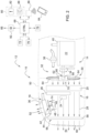
- Fig. 1 shows a schematically illustrated vehicle cooling system 10, which is part of a commercial vehicle designed as an agricultural tractor 12.
- an agricultural tractor 12 is only of an exemplary nature; rather, it can also be any other commercial vehicle from the agricultural or forestry sector as well as a construction vehicle.
- the vehicle cooling system 10 housed in an engine compartment 14 of the agricultural tractor 12 has a first cooler arrangement 16 and a second cooler arrangement 18 which is spatially separated therefrom.
- the first cooler arrangement 16 includes, among other things, in addition to a high-temperature heat exchanger 20 for cooling a diesel engine 22, an oil cooler 24 and an air conditioning condenser 26, the relevant cooler components being located in series and/or parallel in a common main cooling flow 28, which is generated by means of a first fan unit 32 designed as an axial fan 30 is produced.
- the axial fan 30 is set in rotation via a belt drive 34 connected to the diesel engine 22.
- the second cooler arrangement 18 is a charge air cooler 36, which is attached within the engine compartment 14 upstream and essentially horizontally above the main cooling flow 28.
- the Intercooler 36 serves to cool the combustion air that is heated during compression by a turbocharger 38 and is to be supplied to an intake tract 40 of the diesel engine 22 (the hose connections present in this case are in Fig. 1 only indicated for the sake of clarity).
- a second fan unit 42 in the form of a further axial fan 44 is connected upstream, which is driven by a hydraulic motor 46.
- an electric drive in the form of an electric motor can also be provided.
- a secondary cooling stream 48 passing through the intercooler 36 is branched off from the main cooling stream 28.
- the heated secondary cooling stream 48 then leaves the engine compartment 14 via an air outlet opening 52 formed on an upper side of a hood 50 (indicated by dashed lines).
- the ambient air 54 required to generate the main and secondary cooling flow 28, 48 is sucked in via an upstream of the fan units 32, 42 and the cooler arrangements 16 , 18 lying filter element 56.
- the filter element 56 has the shape of a fine-mesh metal sieve 58 constructed as a particle filter, which is located immediately behind a front radiator grille 60 in the hood 50 of the agricultural tractor 12. Deviating from this, the filter element 56 can also be structurally integrated directly into the front radiator grille 60.
- the vehicle cooling system 10 offers the possibility of putting the axial fan 30 of the first cooling arrangement 16 into reversing operation, in which the direction of the main cooling flow 28 is reversed, so that the filter element 56 can be blown out towards the outside environment and cleaned in this way.
- the axial fan 30 comprised by the first fan unit 32 has a plurality of fan blades 64 which project radially from a fan hub 62 and which can be pivoted with respect to their angle of attack ⁇ by means of an adjusting device 66.
- a reversal of the flow direction is possible without changing the direction of rotation of the axial fan 30.
- This operating state is in Fig. 2 reproduced.
- the in Fig. 1 shown spatial arrangement of the fan units 32, 42 or cooler arrangements 16, 18 only represents one of several possibilities.
- the second cooler arrangement 18 is located between the filter element 56 and the first cooler arrangement 16 with respect to the course of the main cooling flow 28, but this can also lie between the first cooler arrangement 16 and the first fan unit 32.
- Fig. 3 shows an exemplary embodiment of the method according to the invention for operating the vehicle system 10, illustrated as a flow chart. Accordingly, the method is started in an initialization step 100, whereupon, in a first step 102, an actual value n ist of a speed variable is determined by a control unit 68, which is one at the second Fan unit 42 represents the speed that occurs depending on the cooling requirement.
- a control unit 68 which is one at the second Fan unit 42 represents the speed that occurs depending on the cooling requirement.
- the cooling requirement dependence of the speed of the second fan unit 42 results from the fact that a reduced cooling performance detected due to a temperature increase is compensated for by means of a successive increase in speed.
- n is the speed variable is determined in the first step 102 by the control unit 68 by sensing the speed of a fan wheel 70 included in the second fan unit 42.
- An inductive speed sensor 72 of a conventional design is used for this purpose, which detects the revolutions of a drive shaft 74 running between the hydraulic motor 46 and the fan wheel 70 without contact and transmits a corresponding speed signal to the control unit 68.
- the actual value n is the speed variable by the control unit 68 in the first step 102 determined mathematically in accordance with control variables intended for the operation of the second fan unit 42.
- the control variables present on a CAN data bus 76 of the agricultural tractor 12 are detected by sensors and, given the control behavior of the hydraulic motor 46, provide a clear statement about the on Fan wheel 70 occurring speed.
- the control variables represent a volume flow and/or pressure of a hydraulic supply provided for operating the hydraulic motor 46.
- these are indirectly derived by the control unit 68 from an electrical signal which serves to actuate a valve (not shown) provided for specifying the volume flow and/or pressure.
- the control variables result from the voltage and/or current of a power supply intended to operate it.
- control unit 68 compares the actual value n ist of the speed variable determined in the first step 102 with a setpoint value n target specified for a cleaned state of the filter element 56.
- control unit 68 detects in a third step 106 that the comparison result is outside a predetermined speed tolerance range ⁇ n, then in a fourth step 108 it generates a trigger signal to cause a reversing operation of the first fan unit 32 in order to control the filter element 56 by means of the first fan unit 32 by reversing the direction of the main cooling flow 28. Otherwise, the method returns to the third step 106.
- an excessive increase in the cooling requirement of the second cooler arrangement 18 derived from a speed discrepancy observed in the fourth step 108 is used as an indicator of the need to carry out a cleaning process of the filter element 56.
- the setpoint n target of the speed variable specified for a cleaned state of the filter element 56 is fixed.
- the setpoint n should is specified in such a way that a maximum expected cooling requirement of the charge air to be cooled by means of the second cooler arrangement 18 is reliably covered.
- the setpoint n target specified for the speed variable is stored in a storage unit 78 that communicates with the control unit 68.
- a second option provides that the setpoint n shall of the speed variable specified for a cleaned state of the filter element 56 is not based firmly on the maximum cooling requirement of the charge air to be cooled by means of the second cooler arrangement 18, but rather on the control unit 68 depending on a determined actual Cooling requirements are variably specified.
- the actual cooling requirement of the charge air is derived by the control unit 68, among other things, from information available via the CAN data bus 76 regarding an engine speed or power of the diesel engine 22, the outside temperature, the air humidity, the charge air pressure and / or the position of adjustable turbocharger blades.
- a user interface 80 is activated by means of the trigger signal to output an operator message informing about the need to carry out a reversing operation.
- the user interface 80 has a touch-sensitive display 82, which is housed in a driver's cab of the agricultural tractor 12 or is part of a mobile terminal 84, which is in data exchange connection with the control unit 68 via a wireless interface 86.
- the operator information is output visually via the touch-sensitive display 82, but also audibly by means of an acoustic signal generator 88 included in the user interface 80.
- a seventh step 114 after an operator release in a preceding sixth step 112, the actuating device 66 encompassed by the first fan unit 32 is controlled by means of the trigger signal for the automatic execution of the reversing operation.
- the adjusting device 66 has an electrically, hydraulically or pneumatically actuated arrangement 90 which is integrated in the fan hub 62 of the fan wheel 70 for changing the angle of attack ⁇ of the fan blades 64.
- the electrical, hydraulic or pneumatic actuation of the arrangement 90 takes place by means of a control unit 92 connected to the control unit 68. If the operator is not released in the sixth step 112, the method is ended immediately in a final step 116.
- the touch-sensitive display 82 included in the user interface 80 is used for the purpose of operator release in the sixth step 112.
- the driver of the agricultural tractor 12 is given the opportunity to first find a suitable parking space, so that the filter element 56 is not blown out in closed buildings such as chafing or workshops can be ruled out.
- the method according to the invention is then ended in the final step 116.
Landscapes
- Engineering & Computer Science (AREA)
- Chemical & Material Sciences (AREA)
- Combustion & Propulsion (AREA)
- Mechanical Engineering (AREA)
- General Engineering & Computer Science (AREA)
- Cooling, Air Intake And Gas Exhaust, And Fuel Tank Arrangements In Propulsion Units (AREA)
Abstract
Description
- Die Erfindung betrifft ein Verfahren zum Betreiben eines Fahrzeugkühlsystems, das ein erstes Lüfteraggregat zur Erzeugung eines eine erste Kühleranordnung beaufschlagenden Hauptkühlstroms sowie ein an den Hauptkühlstrom angrenzendes zweites Lüfteraggregat zur Erzeugung eines eine zweite Kühleranordnung beaufschlagenden Nebenkühlstroms umfasst, wobei der Nebenkühlstrom mittels des zweiten Lüfteraggregats aus dem Hauptkühlstrom abgezweigt wird, und wobei die für die Erzeugung der Kühlströme angesaugte Umgebungsluft ein stromaufwärts der Lüfteraggregate sowie der Kühleranordnungen liegendes Filterelement zur Partikelfilterung passiert.
- Ein derartiges Fahrzeugkühlsystem wird unter anderem in landwirtschaftlichen Traktoren der R-Serie des Herstellers John Deere eingesetzt. Das in einem Motorraum untergebrachte Fahrzeugkühlsystem weist eine erste Kühleranordnung und eine räumlich davon getrennt untergebrachte zweite Kühleranordnung auf. Die erste Kühleranordnung umfasst unter anderem neben einem Hochtemperaturwärmetauscher zur Kühlung eines Dieselmotors einen Ölkühler sowie einen Klimaanlagenkondensor, wobei die betreffenden Kühlerkomponenten seriell und/oder parallel in einem gemeinsamen Hauptkühlstrom liegen, der mittels eines Axiallüfters durch Ansaugung von Umgebungsluft erzeugt wird. Die zweite Kühleranordnung weist einen Ladeluftkühler auf, der innerhalb des Motorraums stromaufwärts sowie im Wesentlichen horizontal verlaufend oberhalb des Hauptkühlstroms angebracht ist. Um einen von der ersten Kühleranordnung unabhängigen Betrieb des Ladeluftkühlers zu ermöglichen, ist diesem ein weiterer Axiallüfter vorgeschaltet, der mittels eines Hydraulikmotors angetrieben wird. Auf diese Weise lässt sich aus dem Hauptkühlstrom ein durch den Ladeluftkühler hindurchtretender Nebenkühlstrom abzweigen. Der erhitzte Nebenkühlstrom verlässt anschließend den Motorraum über eine Luftaustrittsöffnung, die an einer Oberseite einer Motorhaube ausgebildet ist.
- Zum Schutz der Kühleranordnungen des Fahrzeugkühlsystems vor Staubablagerungen und einer damit einhergehenden Degradation der Kühlleistung, erfolgt die Ansaugung der Umgebungsluft über ein Filterelement. Dieses weist die Gestalt eines als Partikelfilter aufgebauten feinmaschigen Metallsiebs auf, das sich unmittelbar hinter einem frontseitigen Kühlergrill in der Motorhaube des landwirtschaftlichen Traktors befindet. Da die Oberfläche des Metallsiebs sich beim Passieren staubhaltiger Umgebungsluft mit der Zeit zusetzt, ist es erforderlich, das Filterelement in regelmäßigen zeitlichen Abständen zu reinigen, wozu basierend auf einer Zeitablaufsteuerung über eine in einer Fahrerkabine befindliche Nutzerschnittstelle die Ausgabe einer entsprechenden Fahreranweisung erfolgen kann. Der Reinigungsvorgang an sich wird üblicherweise von Hand mittels einer von einem Kompressor druckluftgespeisten Ausblaspistole ausgeführt. Manche Fahrzeugkühlsysteme bieten aber auch die Möglichkeit, den Axiallüfter der ersten Kühlanordnung durch Verschwenken zugehöriger Lüfterflügel in einen Reversierbetrieb zu versetzen, in dem die Richtung des Hauptkühlstroms umgekehrt wird, sodass sich das Filterelement zur Außenumgebung hin ausblasen und auf diese Weise reinigen lässt.
- Um den zwischen aufeinanderfolgenden Reinigungsvorgängen am Filterelement anfallenden Staubablagerungen Rechnung zu tragen, wie auch dem Umstand, dass die Einhaltung der Reinigungsintervalle letztlich der Sorgfalt des Bedieners obliegt, muss die von dem Fahrzeugkühlsystem maximal erbringbare Kühlleistung zur Gewährleistung ausreichender "Sicherheitsreserven" entsprechend überdimensioniert werden. Dies gilt vor allem im Hinblick auf die an den Hauptkühlstrom angrenzende bzw. in diesen hineinragende zweite Kühleranordnung, die nicht nur zur Vermeidung unerwünschter Beeinträchtigungen der Kühlung der ersten Kühleranordnung baulich möglichst kompakt ausgebildet sein sollte.
- Vor diesem Hintergrund ist es Aufgabe der vorliegenden Erfindung, ein Verfahren zum Betreiben eines Fahrzeugkühlsystems der eingangs genannten Art hinsichtlich einer Bauraumoptimierung weiterzubilden.
- Diese Aufgabe wird durch ein Verfahren mit den Merkmalen des Patentanspruchs 1 gelöst.
- Bei dem Verfahren zum Betreiben eines Fahrzeugkühlsystems umfasst das Fahrzeugkühlsystem ein erstes Lüfteraggregat zur Erzeugung eines eine erste Kühleranordnung beaufschlagenden Hauptkühlstroms sowie ein an den Hauptkühlstrom angrenzendes zweites Lüfteraggregat zur Erzeugung eines eine zweite Kühleranordnung beaufschlagenden Nebenkühlstroms, wobei der Nebenkühlstrom mittels des zweiten Lüfteraggregats aus dem Hauptkühlstrom abgezweigt wird, und wobei die für die Erzeugung der Kühlströme angesaugte Umgebungsluft ein stromaufwärts der Lüfteraggregate sowie der Kühleranordnungen liegendes Filterelement zur Partikelfilterung passiert. Von einer Kontrolleinheit wird ein Istwert einer sensorisch und/oder rechnerisch ermittelten Drehzahlgröße, die eine am zweiten Lüfteraggregat kühlbedarfsabhängig auftretende Drehzahl wiedergibt, mit einem für einen gereinigten Zustand des Filterelements spezifizierten Sollwert verglichen, wobei für den Fall, dass das Vergleichsergebnis außerhalb eines vorgegebenen Drehzahltoleranzbereichs liegt, von der Kontrolleinheit ein Triggersignal zur Veranlassung eines Reversierbetriebs des ersten Lüfteraggregats erzeugt wird, um das Filterelement mittels des ersten Lüfteraggregats durch Richtungsumkehr des Hauptkühlstroms auszublasen.
- Mit anderen Worten wird eine aus einer beobachteten Drehzahldiskrepanz abgeleitete übermäßige Zunahme des Kühlbedarfs der zweiten Kühleranordnung als Indikator für die Notwendigkeit der Ausführung eines Reinigungsvorgangs des Filterelements herangezogen. Dieses Vorgehen berücksichtigt die tatsächliche Partikelbelastung der angesaugten Umgebungsluft, was bei einer reinen Zeitablaufsteuerung oder dergleichen naturgemäß nicht der Fall ist. Die erforderliche Überdimensionierung der zweiten Kühleranordnung einschließlich des zugehörigen zweiten Lüfteraggregats bemisst sich hierbei an der durch den zulässigen Drehzahltoleranzbereich gegebenen Sicherheitsreserve, kann also baulich dementsprechend kompakt ausfallen.
- Hierbei ergibt sich die Kühlbedarfsabhängigkeit der Drehzahl des zweiten Lüfteraggregats daraus, dass in gängigen Fahrzeugkühlsystemen eine aufgrund eines Temperaturanstiegs erkannte verminderte Kühlleistung im Wege einer sukzessiven Drehzahlanhebung kompensiert wird.
- Bei der zweiten Kühleranordnung handelt es sich typischerweise um einen Ladeluftkühler eines Dieselmotors. Dieser dient der Kühlung der mittels eines Turboladers beim Verdichten erhitzten und einem Ansaugtrakt des Dieselmotors zuzuführenden Verbrennungsluft. Das zweite Lüfteraggregat ist dabei als hydraulisch oder elektrisch angetriebener Axiallüfter ausgebildet.
- Zur Ausführung des Reversierbetriebs kann das ebenfalls als Axiallüfter ausgebildete erste Lüfteraggregat eine Vielzahl von an einer Lüfternabe radial hervorspringenden Lüfterflügeln aufweisen, die sich mittels einer Stelleinrichtung bezüglich ihres Anstellwinkels verschwenken lassen. Auf diese Weise ist eine Umkehr der Strömungsrichtung ohne Änderung der Drehrichtung des Axiallüfters möglich. Letzterer wird hierbei über einen mit dem Dieselmotor verbundenen Riementrieb in Rotation versetzt.
- Vorteilhafte Weiterbildungen des erfindungsgemäßen Verfahrens gehen aus den Unteransprüchen hervor.
- Vorzugsweise wird der Istwert der Drehzahlgröße von der Kontrolleinheit sensorisch durch Erfassung einer Drehzahl eines von dem zweiten Lüfteraggregat umfassten Lüfterrads ermittelt. Hierzu kann ein induktiver Drehzahlsensor herkömmlicher Bauart dienen, der die Umdrehungen einer zwischen Lüfterantrieb und Lüfterrad verlaufenden Antriebswelle berührungslos erfasst sowie ein damit korrespondierendes Drehzahlsignal an die Kontrolleinheit übermittelt.
- Andererseits ist es auch denkbar, dass der Istwert der Drehzahlgröße von der Kontrolleinheit rechnerisch nach Maßgabe einer für den Betrieb des zweiten Lüfteraggregats vorgesehenen Steuergröße ermittelt wird. Erfolgt der Antrieb des Lüfterrads hydraulisch, so können die Steuergrößen einen Volumenstrom und/oder einen Druck einer zum Betrieb eines zugehörigen Hydraulikmotors vorgesehenen Hydraulikversorgung repräsentieren. Diese lassen sich beispielsweise aus einem elektrischen Signal, das der Betätigung eines zur Vorgabe von Volumenstrom und/oder Druck vorgesehenen Ventils dient, mittelbar ableiten. Für den Fall eines elektrischen Antriebs des Lüfterrads ergeben sich die Steuergrößen hingegen aus Spannung und/oder Strom einer zum Betrieb eines zugehörigen Elektromotors vorgesehenen Stromversorgung. Die betreffenden Größen sind sensorisch ohne Weiteres erfassbar und lassen bei bekanntem Steuerverhalten des Hydraulik- bzw. Elektromotors eine eindeutige Aussage über die am Lüfterrad auftretende Drehzahl zu.
- Des Weiteren besteht die Möglichkeit, dass der für einen gereinigten Zustand des Filterelements spezifizierte Sollwert der Drehzahlgröße der Einfachheit halber fest vorgegeben ist. Die Vorgabe des Sollwerts erfolgt derart, dass ein maximal zu erwartender Kühlbedarf einer mittels der zweiten Kühleranordnung zu kühlenden Betriebseinrichtung bzw. eines mittels der zweiten Kühleranordnung zu kühlenden Betriebsmediums verlässlich abgedeckt wird. Der für die Drehzahlgröße vorgegebene Sollwert ist beispielsweise in einer mit der Kontrolleinheit kommunizierenden Speichereinheit hinterlegt.
- Abweichend davon ist es auch vorstellbar, dass der für einen gereinigten Zustand des Filterelements spezifizierte Sollwert der Drehzahlgröße sich nicht fest am maximalem Kühlbedarf der mittels der zweiten Kühleranordnung zu kühlenden Betriebseinrichtung bzw. des mittels der zweiten Kühleranordnung zu kühlenden Betriebsmediums orientiert, sondern von der Kontrolleinheit in Abhängigkeit eines ermittelten tatsächlichen Kühlbedarfs variabel vorgegeben wird. Handelt es sich bei der zweiten Kühleranordnung um einen Ladeluftkühler, so lässt sich der tatsächliche Kühlbedarf der Ladeluft unter anderem aus Angaben hinsichtlich einer Motordrehzahl bzw. -leistung des Dieselmotors, der Außentemperatur, der Luftfeuchtigkeit, des Ladeluftdrucks und/oder der Position verstellbarer Turboladerschaufeln ableiten.
- Zur Initiierung des Reinigungsvorgangs kann vorgesehen sein, dass mittels des Triggersignals eine Nutzerschnittstelle zur Ausgabe eines über die Notwendigkeit der Ausführung eines Reversierbetriebs informierenden Bedienerhinweises angesteuert wird. Die Nutzerschnittstelle weist beispielsweise ein berührungsempfindliches Display auf, das in einer Fahrerkabine eines mit dem Fahrzeugkühlsystem ausgestatteten Nutzfahrzeugs untergebracht oder aber Bestandteil eines mobilen Endgeräts ist, das über eine drahtlose Schnittstelle mit der Kontrolleinheit in Datenaustauschverbindung steht. Die Ausgabe der Bedienerinformation erfolgt visuell über das berührungsempfindliche Display, gegebenenfalls aber auch hörbar mittels eines von der Nutzerschnittstelle umfassten akustischen Signalgebers.
- Ferner besteht die Möglichkeit, dass mittels des Triggersignals eine von dem ersten Lüfteraggregat umfasste Stelleinrichtung zur selbsttätigen Ausführung des Reversierbetriebs angesteuert wird. Hierzu umfasst die Stelleinrichtung eine in einer Lüfternabe des Lüfterrads integrierte elektrisch, hydraulisch oder pneumatisch betätigbare Anordnung zur Veränderung des Anstellwinkels der Lüfterflügel. Die elektrische, hydraulische oder pneumatische Betätigung der Anordnung erfolgt hierbei mittels einer mit der Kontrolleinheit in Verbindung stehenden Steuereinheit.
- Da die Durchführung des Reinigungsvorgangs eine vorübergehende Betriebsunterbrechung eines mit dem Fahrzeugkühlsystem ausgestatteten Nutzfahrzeugs bedingt, ist es von Vorteil, wenn die selbsttätige Ausführung des Reversierbetriebs von der Kontrolleinheit erst nach vorheriger Bedienerfreigabe erfolgt. Für die Zwecke der Bedienerfreigabe kann insbesondere das von der Nutzerschnittstelle umfasste berührungsempfindliche Display dienen. Der Fahrer des Nutzfahrzeugs erhält in diesem Fall die Gelegenheit, zunächst einen geeigneten Stellplatz aufzusuchen, sodass sich ein unerwünschtes Ausblasen des Filterelements in geschlossenen Gebäuden wie Scheuern oder Werkstätten ausschließen lässt.
- Das erfindungsgemäße Verfahren zum Betreiben eines Fahrzeugkühlsystems wird im Folgenden anhand der beigefügten Zeichnungen näher beschrieben. Dabei beziehen sich identische Bezugszeichen auf übereinstimmende oder bezüglich ihrer Funktion vergleichbare Komponenten. Es zeigen:
- Fig. 1
- ein schematisch dargestelltes Fahrzeugkühlsystem eines als landwirtschaftlicher Traktor ausgebildeten Nutzfahrzeugs,
- Fig. 2
- das in
Fig. 1 gezeigte Fahrzeugkühlsystem während der Ausführung eines Reversierbetriebs, und - Fig. 3
- ein als Flussdiagramm veranschaulichtes Ausführungsbeispiel des erfindungsgemäßen Verfahrens zum Betreiben des in
Fig. 1 gezeigten Fahrzeugkühlsystems. -
Fig. 1 zeigt ein schematisch dargestelltes Fahrzeugkühlsystem 10, das Bestandteil eines als landwirtschaftlicher Traktor 12 ausgebildeten Nutzfahrzeugs ist. - Die Darstellung eines landwirtschaftlichen Traktors 12 ist lediglich beispielhafter Natur, vielmehr kann es sich auch um ein beliebiges anderes Nutzfahrzeug aus dem land- oder forstwirtschaftlichen Bereich wie auch um ein Baufahrzeug handeln.
- Das in einem Motorraum 14 des landwirtschaftlichen Traktors 12 untergebrachte Fahrzeugkühlsystem 10 weist eine erste Kühleranordnung 16 und eine räumlich davon getrennt untergebrachte zweite Kühleranordnung 18 auf. Die erste Kühleranordnung 16 umfasst unter anderem neben einem Hochtemperaturwärmetauscher 20 zur Kühlung eines Dieselmotors 22 einen Ölkühler 24 sowie einen Klimaanlagenkondensor 26, wobei die betreffenden Kühlerkomponenten seriell und/oder parallel in einem gemeinsamen Hauptkühlstrom 28 liegen, der mittels eines als Axiallüfter 30 ausgebildeten ersten Lüfteraggregats 32 erzeugt wird. Der Axiallüfter 30 wird hierbei über einen mit dem Dieselmotor 22 verbundenen Riementrieb 34 in Rotation versetzt.
- Weiterhin handelt es sich bei der zweiten Kühleranordnung 18 um einen Ladeluftkühler 36, der innerhalb des Motorraums 14 stromaufwärts sowie im Wesentlichen horizontal verlaufend oberhalb des Hauptkühlstroms 28 angrenzend angebracht ist. Der Ladeluftkühler 36 dient der Kühlung der mittels eines Turboladers 38 beim Verdichten erhitzten und einem Ansaugtrakt 40 des Dieselmotors 22 zuzuführenden Verbrennungsluft (die insofern vorhandenen Schlauchverbindungen sind in
Fig. 1 der Übersichtlichkeit halber lediglich angedeutet). Um einen von der ersten Kühleranordnung 16 unabhängigen Betrieb des Ladeluftkühlers 36 zu ermöglichen, ist ein zweites Lüfteraggregat 42 in Gestalt eines weiteren Axiallüfters 44 vorgeschaltet, der mittels eines Hydraulikmotors 46 angetrieben wird. Anstelle eines derartigen hydraulischen Antriebs kann jedoch auch ein elektrischer Antrieb in Gestalt eines Elektromotors vorgesehen sein. Auf diese Weise wird aus dem Hauptkühlstrom 28 ein durch den Ladeluftkühler 36 hindurchtretender Nebenkühlstrom 48 abgezweigt. Der erhitzte Nebenkühlstrom 48 verlässt anschließend den Motorraum 14 über eine an einer Oberseite einer (strichliniert angedeuteten) Motorhaube 50 ausgebildete Luftaustrittsöffnung 52. - Um die Kühleranordnungen 16, 18 des Fahrzeugkühlsystems 10 vor Staubablagerungen und einer damit einhergehenden Degradation der Kühlleistung zu schützen, erfolgt die Ansaugung der zur Erzeugung von Haupt- und Nebenkühlstrom 28, 48 erforderlichen Umgebungsluft 54 über ein stromaufwärts der Lüfteraggregate 32, 42 sowie der Kühleranordnungen 16, 18 liegendes Filterelement 56. Das Filterelement 56 weist die Gestalt eines als Partikelfilter aufgebauten feinmaschigen Metallsiebs 58 auf, das sich unmittelbar hinter einem frontseitigen Kühlergrill 60 in der Motorhaube 50 des landwirtschaftlichen Traktors 12 befindet. Abweichend davon kann das Filterelement 56 auch unmittelbar in den frontseitigen Kühlergrill 60 baulich integriert sein.
- Da die Oberfläche des Metallsiebs 58 sich beim Passieren staubhaltiger Umgebungsluft 54 mit der Zeit zusetzt, ist es erforderlich, das Filterelement 56 in regelmäßigen Abständen zu reinigen. Das Fahrzeugkühlsystem 10 bietet hierzu die Möglichkeit, den Axiallüfter 30 der ersten Kühlanordnung 16 in einen Reversierbetrieb zu versetzen, in dem die Richtung des Hauptkühlstroms 28 umgekehrt wird, sodass sich das Filterelement 56 zur Außenumgebung hin ausblasen und auf diese Weise reinigen lässt.
- Genauer gesagt weist der von dem ersten Lüfteraggregat 32 umfasste Axiallüfter 30 zur Ausführung des Reversierbetriebs eine Vielzahl von an einer Lüfternabe 62 radial hervorspringenden Lüfterflügeln 64 auf, die sich mittels einer Stelleinrichtung 66 bezüglich ihres Anstellwinkels α verschwenken lassen. Auf diese Weise ist eine Umkehr der Strömungsrichtung ohne Änderung der Drehrichtung des Axiallüfters 30 möglich. Dieser Betriebszustand ist in
Fig. 2 wiedergegeben. - Der Vollständigkeit halber sei angemerkt, dass die in
Fig. 1 dargestellte räumliche Anordnung der Lüfteraggregate 32, 42 bzw. Kühleranordnungen 16, 18 lediglich eine von mehreren Möglichkeiten wiedergibt. Vorliegend befindet sich die zweite Kühleranordnung 18 bezüglich des Verlaufs des Hauptkühlstroms 28 zwischen dem Filterelement 56 und der ersten Kühleranordnung 16, diese kann jedoch auch zwischen der ersten Kühleranordnung 16 und dem ersten Lüfteraggregat 32 liegen. - Die Funktion der in
Fig. 1 dargestellten weiteren Komponenten soll nachfolgend in Verbindung mit dem inFig. 3 wiedergegebenen Verfahrensablauf erläutert werden. -
Fig. 3 zeigt hierbei ein als Flussdiagramm veranschaulichtes Ausführungsbeispiel des erfindungsgemäßen Verfahrens zum Betreiben des Fahrzeugsystems 10. Demgemäß wird das Verfahren in einem Initialisierungsschritt 100 gestartet, woraufhin in einem ersten Schritt 102 von einer Kontrolleinheit 68 ein Istwert nist einer Drehzahlgröße ermittelt wird, die eine an dem zweiten Lüfteraggregat 42 kühlbedarfsabhängig auftretende Drehzahl wiedergibt. Die Kühlbedarfsabhängigkeit der Drehzahl des zweiten Lüfteraggregats 42 ergibt sich vorliegend daraus, dass eine aufgrund eines Temperaturanstiegs erkannte verminderte Kühlleistung im Wege einer sukzessiven Drehzahlanhebung kompensiert wird. - Der Istwert nist der Drehzahlgröße wird im ersten Schritt 102 von der Kontrolleinheit 68 sensorisch durch Erfassung der Drehzahl eines von dem zweiten Lüfteraggregat 42 umfassten Lüfterrads 70 ermittelt. Hierzu dient ein induktiver Drehzahlsensor 72 herkömmlicher Bauart, der die Umdrehungen einer zwischen Hydraulikmotor 46 und Lüfterrad 70 verlaufenden Antriebswelle 74 berührungslos erfasst sowie ein damit korrespondierendes Drehzahlsignal an die Kontrolleinheit 68 übermittelt.
- Alternativ wird der Istwert nist der Drehzahlgröße von der Kontrolleinheit 68 im ersten Schritt 102 rechnerisch nach Maßgabe von für den Betrieb des zweiten Lüfteraggregats 42 vorgesehenen Steuergrößen ermittelt. Die an einem CAN-Datenbus 76 des landwirtschaftlichen Traktors 12 anstehenden Steuergrößen werden sensorisch erfasst und lassen bei bekanntem Steuerverhalten des Hydraulikmotors 46 eine eindeutige Aussage über die am Lüfterrad 70 auftretende Drehzahl zu. Die Steuergrößen repräsentieren vorliegend einen Volumenstrom und/oder Druck einer zum Betrieb des Hydraulikmotors 46 vorgesehenen Hydraulikversorgung. Vorliegend werden diese von der Kontrolleinheit 68 aus einem elektrischen Signal, das der Betätigung eines zur Vorgabe von Volumenstrom und/oder Druck vorgesehenen (nicht gezeigten) Ventils dient, mittelbar abgeleitet. Für den Fall der Verwendung eines Elektromotors ergeben sich die Steuergrößen hingegen aus Spannung und/oder Strom einer zu dessen Betrieb vorgesehenen Stromversorgung.
- In einem zweiten Schritt 104 wird von der Kontrolleinheit 68 der im ersten Schritt 102 ermittelte Istwert nist der Drehzahlgröße mit einem für einen gereinigten Zustand des Filterelements 56 spezifizierten Sollwert nsoll verglichen.
- Erkennt die Kontrolleinheit 68 in einem dritten Schritt 106, dass das Vergleichsergebnis außerhalb eines vorgegebenen Drehzahltoleranzbereichs Δn liegt, so wird von dieser in einem vierten Schritt 108 ein Triggersignal zur Veranlassung eines Reversierbetriebs des ersten Lüfteraggregats 32 erzeugt, um das Filterelement 56 mittels des ersten Lüfteraggregats 32 durch Richtungsumkehr des Hauptkühlstroms 28 auszublasen. Andernfalls kehrt das Verfahren wieder zum dritten Schritt 106 zurück.
- Mit anderen Worten wird eine aus einer im vierten Schritt 108 beobachteten Drehzahldiskrepanz abgeleitete übermäßige Zunahme des Kühlbedarfs der zweiten Kühleranordnung 18 als Indikator für die Notwendigkeit der Ausführung eines Reinigungsvorgangs des Filterelements 56 herangezogen.
- Entsprechend einer ersten Option ist der für einen gereinigten Zustand des Filterelements 56 spezifizierte Sollwert nsoll der Drehzahlgröße fest vorgegeben. Die Vorgabe des Sollwerts nsoll erfolgt derart, dass ein maximal zu erwartender Kühlbedarf der mittels der zweiten Kühleranordnung 18 zu kühlenden Ladeluft verlässlich abgedeckt wird. Der für die Drehzahlgröße vorgegebene Sollwert nsoll ist in einer mit der Kontrolleinheit 68 kommunizierenden Speichereinheit 78 hinterlegt.
- Abweichend davon sieht eine zweite Option vor, dass der für einen gereinigten Zustand des Filterelements 56 spezifizierte Sollwert nsoll der Drehzahlgröße sich nicht fest am maximalem Kühlbedarf der mittels der zweiten Kühleranordnung 18 zu kühlenden Ladeluft orientiert, sondern von der Kontrolleinheit 68 in Abhängigkeit eines ermittelten tatsächlichen Kühlbedarfs variabel vorgegeben wird. Der tatsächliche Kühlbedarf der Ladeluft wird von der Kontrolleinheit 68 unter anderem aus über den CAN-Datenbus 76 verfügbaren Angaben hinsichtlich einer Motordrehzahl bzw. -leistung des Dieselmotors 22, der Außentemperatur, der Luftfeuchtigkeit, des Ladeluftdrucks und/oder der Position verstellbarer Turboladerschaufeln abgeleitet.
- Zur Initiierung des Reinigungsvorgangs ist in einem fünften Schritt 110 vorgesehen, dass mittels des Triggersignals eine Nutzerschnittstelle 80 zur Ausgabe eines über die Notwendigkeit der Ausführung eines Reversierbetriebs informierenden Bedienerhinweises angesteuert wird. Die Nutzerschnittstelle 80 weist ein berührungsempfindliches Display 82 auf, das in einer Fahrerkabine des landwirtschaftlichen Traktors 12 untergebracht oder aber Bestandteil eines mobilen Endgeräts 84 ist, das über eine drahtlose Schnittstelle 86 mit der Kontrolleinheit 68 in Datenaustauschverbindung steht. Die Ausgabe der Bedienerinformation erfolgt visuell über das berührungsempfindliche Display 82, aber auch hörbar mittels eines von der Nutzerschnittstelle 80 umfassten akustischen Signalgebers 88.
- Hierbei wird in einem siebten Schritt 114 nach einer in einem vorgeschalteten sechsten Schritt 112 erfolgten Bedienerfreigabe mittels des Triggersignals die von dem ersten Lüfteraggregat 32 umfasste Stelleinrichtung 66 zur selbsttätigen Ausführung des Reversierbetriebs angesteuert. Hierzu weist die Stelleinrichtung 66 eine in der Lüfternabe 62 des Lüfterrads 70 integrierte elektrisch, hydraulisch oder pneumatisch betätigbare Anordnung 90 zur Veränderung des Anstellwinkels α der Lüfterflügel 64 auf. Die elektrische, hydraulische oder pneumatische Betätigung der Anordnung 90 erfolgt hierbei mittels einer mit der Kontrolleinheit 68 in Verbindung stehenden Steuereinheit 92. Unterbleibt im sechsten Schritt 112 die Bedienerfreigabe, so wird das Verfahren unmittelbar in einem Schlussschritt 116 beendet.
- Für die Zwecke der Bedienerfreigabe im sechsten Schritt 112 dient das von der Nutzerschnittstelle 80 umfasste berührungsempfindliche Display 82. Der Fahrer des landwirtschaftlichen Traktors 12 erhält in diesem Fall die Gelegenheit, zunächst einen geeigneten Stellplatz aufzusuchen, sodass sich ein unerwünschtes Ausblasen des Filterelements 56 in geschlossenen Gebäuden wie Scheuern oder Werkstätten ausschließen lässt.
- Anschließend wird das erfindungsgemäße Verfahren im Schlussschritt 116 beendet.
Claims (8)
- Verfahren zum Betreiben eines Fahrzeugkühlsystems, das ein erstes Lüfteraggregat (32) zur Erzeugung eines eine erste Kühleranordnung (16) beaufschlagenden Hauptkühlstroms (28) sowie ein an den Hauptkühlstrom (28) angrenzendes zweites Lüfteraggregat (42) zur Erzeugung eines eine zweite Kühleranordnung (18) beaufschlagenden Nebenkühlstroms (48) umfasst, wobei der Nebenkühlstrom (48) mittels des zweiten Lüfteraggregats (42) aus dem Hauptkühlstrom (28) abgezweigt wird, und wobei die für die Erzeugung der Kühlströme (28, 48) angesaugte Umgebungsluft (54) ein stromaufwärts der Lüfteraggregate (32, 42) sowie der Kühleranordnungen (16, 18) liegendes Filterelement (56) zur Partikelfilterung passiert, dadurch gekennzeichnet, dass von einer Kontrolleinheit (68) ein Istwert (nist) einer sensorisch und/oder rechnerisch ermittelten Drehzahlgröße, die eine am zweiten Lüfteraggregat (42) kühlbedarfsabhängig auftretende Drehzahl wiedergibt, mit einem für einen gereinigten Zustand des Filterelements (56) spezifizierten Sollwert (nsoll) verglichen wird, wobei für den Fall, dass das Vergleichsergebnis außerhalb eines vorgegebenen Drehzahltoleranzbereichs (Δn) liegt, von der Kontrolleinheit (68) ein Triggersignal zur Veranlassung eines Reversierbetriebs des ersten Lüfteraggregats (32) erzeugt wird, um das Filterelement (56) mittels des ersten Lüfteraggregats (32) durch Richtungsumkehr des Hauptkühlstroms (28) auszublasen.
- Verfahren nach Anspruch 1, dadurch gekennzeichnet, dass der Istwert (nist) der Drehzahlgröße von der Kontrolleinheit (68) sensorisch durch Erfassung einer Drehzahl eines von dem zweiten Lüfteraggregat (42) umfassten Lüfterrads (70) ermittelt wird.
- Verfahren nach Anspruch 1 oder 2, dadurch gekennzeichnet, dass der Istwert (nist) der Drehzahlgröße von der Kontrolleinheit (68) rechnerisch nach Maßgabe einer für den Betrieb des zweiten Lüfteraggregats (42) vorgesehenen Steuergröße ermittelt wird.
- Verfahren nach wenigstens einem der Ansprüche 1 bis 3, dadurch gekennzeichnet, dass der für einen gereinigten Zustand des Filterelements (56) spezifizierte Sollwert (nsoll) der Drehzahlgröße fest vorgegeben ist.
- Verfahren nach wenigstens einem der Ansprüche 1 bis 3, dadurch gekennzeichnet, dass der für einen gereinigten Zustand des Filterelements (56) spezifizierte Sollwert (nsoll) der Drehzahlgröße von der Kontrolleinheit (68) in Abhängigkeit eines ermittelten tatsächlichen Kühlbedarfs variabel vorgegeben wird.
- Verfahren nach wenigstens einem der Ansprüche 1 bis 5, dadurch gekennzeichnet, dass mittels des Triggersignals eine Nutzerschnittstelle (80) zur Ausgabe eines über die Notwendigkeit der Ausführung eines Reversierbetriebs informierenden Bedienerhinweises angesteuert wird.
- Verfahren nach wenigstens einem der Ansprüche 1 bis 6, dadurch gekennzeichnet, dass mittels des Triggersignals eine von dem ersten Lüfteraggregat (32) umfasste Stelleinrichtung (66) zur selbsttätigen Ausführung des Reversierbetriebs angesteuert wird.
- Verfahren nach Anspruch 7, dadurch gekennzeichnet, dass die selbsttätige Ausführung des Reversierbetriebs von der Kontrolleinheit (68) erst nach vorheriger Bedienerfreigabe erfolgt.
Applications Claiming Priority (1)
| Application Number | Priority Date | Filing Date | Title |
|---|---|---|---|
| DE102022106777.7A DE102022106777A1 (de) | 2022-03-23 | 2022-03-23 | Verfahren zum Betreiben eines Fahrzeugkühlsystems |
Publications (2)
| Publication Number | Publication Date |
|---|---|
| EP4257809A1 true EP4257809A1 (de) | 2023-10-11 |
| EP4257809B1 EP4257809B1 (de) | 2025-01-22 |
Family
ID=85505468
Family Applications (1)
| Application Number | Title | Priority Date | Filing Date |
|---|---|---|---|
| EP23160117.0A Active EP4257809B1 (de) | 2022-03-23 | 2023-03-06 | Verfahren zum betreiben eines fahrzeugkühlsystems |
Country Status (3)
| Country | Link |
|---|---|
| US (1) | US12025048B2 (de) |
| EP (1) | EP4257809B1 (de) |
| DE (1) | DE102022106777A1 (de) |
Cited By (1)
| Publication number | Priority date | Publication date | Assignee | Title |
|---|---|---|---|---|
| EP4438865A1 (de) * | 2023-03-01 | 2024-10-02 | Deere & Company | Verfahren zum betreiben eines fahrzeugkühlsystems |
Citations (4)
| Publication number | Priority date | Publication date | Assignee | Title |
|---|---|---|---|---|
| EP2757233A1 (de) * | 2013-01-18 | 2014-07-23 | Deere & Company | Kühlungsanordnung für ein Kraftfahrzeug |
| DE102014208553A1 (de) * | 2014-05-07 | 2015-11-12 | Deere & Company | Landwirtschaftliches Arbeitsfahrzeug |
| US20170112054A1 (en) * | 2015-10-26 | 2017-04-27 | Deere & Company | Harvester reversing engine fan |
| FR3093303A1 (fr) * | 2019-02-28 | 2020-09-04 | Valeo Systemes Thermiques | Vehicule automobile comprenant un systeme de regulation thermique |
Family Cites Families (8)
| Publication number | Priority date | Publication date | Assignee | Title |
|---|---|---|---|---|
| US9010129B2 (en) * | 2009-05-26 | 2015-04-21 | Harvey D. Lilke | Thermoelectric cooling systems and engines |
| US9789744B2 (en) * | 2011-09-23 | 2017-10-17 | Carrier Corporation | Transport refrigeration system utilizing engine waste heat |
| US20130153180A1 (en) | 2011-12-16 | 2013-06-20 | Joseph M. Montocchio | Cooling System With Dual Reversing Fans |
| US8960349B2 (en) | 2013-04-16 | 2015-02-24 | Deere & Company | Hydraulic fluid warm-up using hydraulic fan reversal |
| US9586473B2 (en) * | 2013-07-15 | 2017-03-07 | Deere & Company | Vehicle with selectively reversible cooling fan |
| US9599009B2 (en) | 2014-07-22 | 2017-03-21 | Deere & Company | Reversible mechanical fan |
| US10479191B2 (en) * | 2017-12-19 | 2019-11-19 | Cnh Industrial America Llc | Cooling systems and methods for an agricultural harvester |
| US11091026B2 (en) * | 2019-04-25 | 2021-08-17 | Deere & Company | Cooling system air intake with an adjustable louver |
-
2022
- 2022-03-23 DE DE102022106777.7A patent/DE102022106777A1/de active Pending
-
2023
- 2023-01-26 US US18/159,874 patent/US12025048B2/en active Active
- 2023-03-06 EP EP23160117.0A patent/EP4257809B1/de active Active
Patent Citations (4)
| Publication number | Priority date | Publication date | Assignee | Title |
|---|---|---|---|---|
| EP2757233A1 (de) * | 2013-01-18 | 2014-07-23 | Deere & Company | Kühlungsanordnung für ein Kraftfahrzeug |
| DE102014208553A1 (de) * | 2014-05-07 | 2015-11-12 | Deere & Company | Landwirtschaftliches Arbeitsfahrzeug |
| US20170112054A1 (en) * | 2015-10-26 | 2017-04-27 | Deere & Company | Harvester reversing engine fan |
| FR3093303A1 (fr) * | 2019-02-28 | 2020-09-04 | Valeo Systemes Thermiques | Vehicule automobile comprenant un systeme de regulation thermique |
Cited By (2)
| Publication number | Priority date | Publication date | Assignee | Title |
|---|---|---|---|---|
| EP4438865A1 (de) * | 2023-03-01 | 2024-10-02 | Deere & Company | Verfahren zum betreiben eines fahrzeugkühlsystems |
| US12497915B2 (en) | 2023-03-01 | 2025-12-16 | Deere & Company | Method for operating a vehicle cooling system |
Also Published As
| Publication number | Publication date |
|---|---|
| US20230304433A1 (en) | 2023-09-28 |
| EP4257809B1 (de) | 2025-01-22 |
| US12025048B2 (en) | 2024-07-02 |
| DE102022106777A1 (de) | 2023-09-28 |
Similar Documents
| Publication | Publication Date | Title |
|---|---|---|
| DE102009040796B4 (de) | Verfahren zum Entfernen von Ölansammlungen aus Kältemittelleitungen eines Fahrzeugheizungs-, -lüftungs- und -klimatisierungs-Systems mit mehreren Kältemittelkreisen | |
| EP4257809B1 (de) | Verfahren zum betreiben eines fahrzeugkühlsystems | |
| DE102014207566A1 (de) | KFZ-Luftklappenanordnung mit sensorischer Stellungserfassung | |
| DE112017006613T5 (de) | Steuermodul | |
| DE102019131257A1 (de) | Systeme und verfahren zur überwachung der leistung eines wärmetauschers | |
| WO2021148183A1 (de) | Verfahren zum betreiben eines brennstoffzellensystems, brennstoffzellensystem | |
| DE102021106205A1 (de) | Kühlvorrichtung für ein Fahrzeug, Fahrzeug mit einer Kühlvorrichtung und Verfahren zum Reinigen der Kühlvorrichtung | |
| DE102014213099A1 (de) | Kraftfahrzeug und Anpassungsverfahren | |
| EP4392279A1 (de) | Antriebsstrang-kühleinheit für ein fahrzeug | |
| DE102016002518A1 (de) | Verfahren zum Betreiben eines Kraftfahrzeugs | |
| WO2006008221A1 (de) | Verfahren zum betrieb einer gasturbogruppe | |
| DE102014208545A1 (de) | Vorrichtung zur Kühlung von Ladeluft | |
| WO2013029794A1 (de) | Vorrichtung und verfahren zur steuerung eines lüfterantriebs | |
| DE102017200948A1 (de) | Verfahren zum Betrieb einer turboaufgeladenen Brennkraftmaschine | |
| DE112016006597T5 (de) | Kühlungssystem für eine Hochspannungsausstattung für Fahrzeuge mit Elektroantrieb | |
| DE102019133489A1 (de) | Nachheizverfahren zum Betreiben einer Kälteanlage für ein Kraftfahrzeug, Kälteanlage und Kraftfahrzeug mit einer solchen Kälteanlage | |
| DE102007025727B4 (de) | Verfahren zur Steuerung eines Lüfters sowie Klimaanlage für ein Fahrzeug | |
| EP4438865A1 (de) | Verfahren zum betreiben eines fahrzeugkühlsystems | |
| DE102014210026A1 (de) | Verfahren und Steuerung zum Steuern eines Aufladungssystems für eine Verbrennungskraftmaschine | |
| DE102012006141B4 (de) | Abgaswärmenutzsystem | |
| DE102014208553B4 (de) | Landwirtschaftliches Arbeitsfahrzeug | |
| DE102022102986A1 (de) | Verfahren zum Betreiben eines Kältemittelkreises und Kraftfahrzeug | |
| DE102022106496A1 (de) | Drucklufterzeugungseinrichtung eines Fahrzeugs und Verfahren zu deren Betreiben | |
| DE102011107081A1 (de) | Verfahren und Vorrichtung zum Konditionieren der Luft im Innenraum eines Fahrzeuges | |
| DE102008038083A1 (de) | Brennstoffzellensystem für ein Kraftfahrzeug |
Legal Events
| Date | Code | Title | Description |
|---|---|---|---|
| PUAI | Public reference made under article 153(3) epc to a published international application that has entered the european phase |
Free format text: ORIGINAL CODE: 0009012 |
|
| STAA | Information on the status of an ep patent application or granted ep patent |
Free format text: STATUS: THE APPLICATION HAS BEEN PUBLISHED |
|
| AK | Designated contracting states |
Kind code of ref document: A1 Designated state(s): AL AT BE BG CH CY CZ DE DK EE ES FI FR GB GR HR HU IE IS IT LI LT LU LV MC ME MK MT NL NO PL PT RO RS SE SI SK SM TR |
|
| STAA | Information on the status of an ep patent application or granted ep patent |
Free format text: STATUS: REQUEST FOR EXAMINATION WAS MADE |
|
| 17P | Request for examination filed |
Effective date: 20240411 |
|
| RBV | Designated contracting states (corrected) |
Designated state(s): AL AT BE BG CH CY CZ DE DK EE ES FI FR GB GR HR HU IE IS IT LI LT LU LV MC ME MK MT NL NO PL PT RO RS SE SI SK SM TR |
|
| GRAP | Despatch of communication of intention to grant a patent |
Free format text: ORIGINAL CODE: EPIDOSNIGR1 |
|
| STAA | Information on the status of an ep patent application or granted ep patent |
Free format text: STATUS: GRANT OF PATENT IS INTENDED |
|
| INTG | Intention to grant announced |
Effective date: 20240926 |
|
| GRAS | Grant fee paid |
Free format text: ORIGINAL CODE: EPIDOSNIGR3 |
|
| GRAA | (expected) grant |
Free format text: ORIGINAL CODE: 0009210 |
|
| STAA | Information on the status of an ep patent application or granted ep patent |
Free format text: STATUS: THE PATENT HAS BEEN GRANTED |
|
| AK | Designated contracting states |
Kind code of ref document: B1 Designated state(s): AL AT BE BG CH CY CZ DE DK EE ES FI FR GB GR HR HU IE IS IT LI LT LU LV MC ME MK MT NL NO PL PT RO RS SE SI SK SM TR |
|
| REG | Reference to a national code |
Ref country code: GB Ref legal event code: FG4D Free format text: NOT ENGLISH |
|
| REG | Reference to a national code |
Ref country code: CH Ref legal event code: EP |
|
| REG | Reference to a national code |
Ref country code: IE Ref legal event code: FG4D Free format text: LANGUAGE OF EP DOCUMENT: GERMAN |
|
| REG | Reference to a national code |
Ref country code: DE Ref legal event code: R096 Ref document number: 502023000478 Country of ref document: DE |
|
| REG | Reference to a national code |
Ref country code: NL Ref legal event code: MP Effective date: 20250122 |
|
| PG25 | Lapsed in a contracting state [announced via postgrant information from national office to epo] |
Ref country code: NL Free format text: LAPSE BECAUSE OF FAILURE TO SUBMIT A TRANSLATION OF THE DESCRIPTION OR TO PAY THE FEE WITHIN THE PRESCRIBED TIME-LIMIT Effective date: 20250122 |
|
| PG25 | Lapsed in a contracting state [announced via postgrant information from national office to epo] |
Ref country code: RS Free format text: LAPSE BECAUSE OF FAILURE TO SUBMIT A TRANSLATION OF THE DESCRIPTION OR TO PAY THE FEE WITHIN THE PRESCRIBED TIME-LIMIT Effective date: 20250422 |
|
| PG25 | Lapsed in a contracting state [announced via postgrant information from national office to epo] |
Ref country code: FI Free format text: LAPSE BECAUSE OF FAILURE TO SUBMIT A TRANSLATION OF THE DESCRIPTION OR TO PAY THE FEE WITHIN THE PRESCRIBED TIME-LIMIT Effective date: 20250122 |
|
| PG25 | Lapsed in a contracting state [announced via postgrant information from national office to epo] |
Ref country code: PL Free format text: LAPSE BECAUSE OF FAILURE TO SUBMIT A TRANSLATION OF THE DESCRIPTION OR TO PAY THE FEE WITHIN THE PRESCRIBED TIME-LIMIT Effective date: 20250122 |
|
| PG25 | Lapsed in a contracting state [announced via postgrant information from national office to epo] |
Ref country code: ES Free format text: LAPSE BECAUSE OF FAILURE TO SUBMIT A TRANSLATION OF THE DESCRIPTION OR TO PAY THE FEE WITHIN THE PRESCRIBED TIME-LIMIT Effective date: 20250122 |
|
| REG | Reference to a national code |
Ref country code: LT Ref legal event code: MG9D |
|
| PG25 | Lapsed in a contracting state [announced via postgrant information from national office to epo] |
Ref country code: IS Free format text: LAPSE BECAUSE OF FAILURE TO SUBMIT A TRANSLATION OF THE DESCRIPTION OR TO PAY THE FEE WITHIN THE PRESCRIBED TIME-LIMIT Effective date: 20250522 Ref country code: NO Free format text: LAPSE BECAUSE OF FAILURE TO SUBMIT A TRANSLATION OF THE DESCRIPTION OR TO PAY THE FEE WITHIN THE PRESCRIBED TIME-LIMIT Effective date: 20250422 |
|
| PGFP | Annual fee paid to national office [announced via postgrant information from national office to epo] |
Ref country code: IT Payment date: 20250331 Year of fee payment: 3 |
|
| PG25 | Lapsed in a contracting state [announced via postgrant information from national office to epo] |
Ref country code: HR Free format text: LAPSE BECAUSE OF FAILURE TO SUBMIT A TRANSLATION OF THE DESCRIPTION OR TO PAY THE FEE WITHIN THE PRESCRIBED TIME-LIMIT Effective date: 20250122 |
|
| PG25 | Lapsed in a contracting state [announced via postgrant information from national office to epo] |
Ref country code: LV Free format text: LAPSE BECAUSE OF FAILURE TO SUBMIT A TRANSLATION OF THE DESCRIPTION OR TO PAY THE FEE WITHIN THE PRESCRIBED TIME-LIMIT Effective date: 20250122 Ref country code: PT Free format text: LAPSE BECAUSE OF FAILURE TO SUBMIT A TRANSLATION OF THE DESCRIPTION OR TO PAY THE FEE WITHIN THE PRESCRIBED TIME-LIMIT Effective date: 20250522 |
|
| PG25 | Lapsed in a contracting state [announced via postgrant information from national office to epo] |
Ref country code: GR Free format text: LAPSE BECAUSE OF FAILURE TO SUBMIT A TRANSLATION OF THE DESCRIPTION OR TO PAY THE FEE WITHIN THE PRESCRIBED TIME-LIMIT Effective date: 20250423 Ref country code: BG Free format text: LAPSE BECAUSE OF FAILURE TO SUBMIT A TRANSLATION OF THE DESCRIPTION OR TO PAY THE FEE WITHIN THE PRESCRIBED TIME-LIMIT Effective date: 20250122 |
|
| PG25 | Lapsed in a contracting state [announced via postgrant information from national office to epo] |
Ref country code: SE Free format text: LAPSE BECAUSE OF FAILURE TO SUBMIT A TRANSLATION OF THE DESCRIPTION OR TO PAY THE FEE WITHIN THE PRESCRIBED TIME-LIMIT Effective date: 20250122 |
|
| PG25 | Lapsed in a contracting state [announced via postgrant information from national office to epo] |
Ref country code: SM Free format text: LAPSE BECAUSE OF FAILURE TO SUBMIT A TRANSLATION OF THE DESCRIPTION OR TO PAY THE FEE WITHIN THE PRESCRIBED TIME-LIMIT Effective date: 20250122 |
|
| PG25 | Lapsed in a contracting state [announced via postgrant information from national office to epo] |
Ref country code: DK Free format text: LAPSE BECAUSE OF FAILURE TO SUBMIT A TRANSLATION OF THE DESCRIPTION OR TO PAY THE FEE WITHIN THE PRESCRIBED TIME-LIMIT Effective date: 20250122 |
|
| PG25 | Lapsed in a contracting state [announced via postgrant information from national office to epo] |
Ref country code: MC Free format text: LAPSE BECAUSE OF FAILURE TO SUBMIT A TRANSLATION OF THE DESCRIPTION OR TO PAY THE FEE WITHIN THE PRESCRIBED TIME-LIMIT Effective date: 20250122 |
|
| PG25 | Lapsed in a contracting state [announced via postgrant information from national office to epo] |
Ref country code: CZ Free format text: LAPSE BECAUSE OF FAILURE TO SUBMIT A TRANSLATION OF THE DESCRIPTION OR TO PAY THE FEE WITHIN THE PRESCRIBED TIME-LIMIT Effective date: 20250122 Ref country code: EE Free format text: LAPSE BECAUSE OF FAILURE TO SUBMIT A TRANSLATION OF THE DESCRIPTION OR TO PAY THE FEE WITHIN THE PRESCRIBED TIME-LIMIT Effective date: 20250122 |
|
| REG | Reference to a national code |
Ref country code: DE Ref legal event code: R097 Ref document number: 502023000478 Country of ref document: DE |
|
| PG25 | Lapsed in a contracting state [announced via postgrant information from national office to epo] |
Ref country code: RO Free format text: LAPSE BECAUSE OF FAILURE TO SUBMIT A TRANSLATION OF THE DESCRIPTION OR TO PAY THE FEE WITHIN THE PRESCRIBED TIME-LIMIT Effective date: 20250122 |
|
| PG25 | Lapsed in a contracting state [announced via postgrant information from national office to epo] |
Ref country code: SK Free format text: LAPSE BECAUSE OF FAILURE TO SUBMIT A TRANSLATION OF THE DESCRIPTION OR TO PAY THE FEE WITHIN THE PRESCRIBED TIME-LIMIT Effective date: 20250122 |
|
| PG25 | Lapsed in a contracting state [announced via postgrant information from national office to epo] |
Ref country code: LU Free format text: LAPSE BECAUSE OF NON-PAYMENT OF DUE FEES Effective date: 20250306 |
|
| PLBE | No opposition filed within time limit |
Free format text: ORIGINAL CODE: 0009261 |
|
| STAA | Information on the status of an ep patent application or granted ep patent |
Free format text: STATUS: NO OPPOSITION FILED WITHIN TIME LIMIT |
|
| REG | Reference to a national code |
Ref country code: BE Ref legal event code: MM Effective date: 20250331 |
|
| 26N | No opposition filed |
Effective date: 20251023 |
|
| PG25 | Lapsed in a contracting state [announced via postgrant information from national office to epo] |
Ref country code: BE Free format text: LAPSE BECAUSE OF NON-PAYMENT OF DUE FEES Effective date: 20250331 |
|
| PG25 | Lapsed in a contracting state [announced via postgrant information from national office to epo] |
Ref country code: IE Free format text: LAPSE BECAUSE OF NON-PAYMENT OF DUE FEES Effective date: 20250306 |
|
| PGFP | Annual fee paid to national office [announced via postgrant information from national office to epo] |
Ref country code: DE Payment date: 20260219 Year of fee payment: 4 |
|
| PGFP | Annual fee paid to national office [announced via postgrant information from national office to epo] |
Ref country code: AT Payment date: 20260301 Year of fee payment: 4 |
|
| PGFP | Annual fee paid to national office [announced via postgrant information from national office to epo] |
Ref country code: FR Payment date: 20260325 Year of fee payment: 4 |