EP4255780B1 - Verfahren zum betreiben eines bremssystems eines kraftfahrzeugs - Google Patents
Verfahren zum betreiben eines bremssystems eines kraftfahrzeugs Download PDFInfo
- Publication number
- EP4255780B1 EP4255780B1 EP21805924.4A EP21805924A EP4255780B1 EP 4255780 B1 EP4255780 B1 EP 4255780B1 EP 21805924 A EP21805924 A EP 21805924A EP 4255780 B1 EP4255780 B1 EP 4255780B1
- Authority
- EP
- European Patent Office
- Prior art keywords
- brake
- motor vehicle
- determined
- standstill
- speed
- Prior art date
- Legal status (The legal status is an assumption and is not a legal conclusion. Google has not performed a legal analysis and makes no representation as to the accuracy of the status listed.)
- Active
Links
Images

Classifications
-
- B—PERFORMING OPERATIONS; TRANSPORTING
- B60—VEHICLES IN GENERAL
- B60T—VEHICLE BRAKE CONTROL SYSTEMS OR PARTS THEREOF; BRAKE CONTROL SYSTEMS OR PARTS THEREOF, IN GENERAL; ARRANGEMENT OF BRAKING ELEMENTS ON VEHICLES IN GENERAL; PORTABLE DEVICES FOR PREVENTING UNWANTED MOVEMENT OF VEHICLES; VEHICLE MODIFICATIONS TO FACILITATE COOLING OF BRAKES
- B60T8/00—Arrangements for adjusting wheel-braking force to meet varying vehicular or ground-surface conditions, e.g. limiting or varying distribution of braking force
- B60T8/32—Arrangements for adjusting wheel-braking force to meet varying vehicular or ground-surface conditions, e.g. limiting or varying distribution of braking force responsive to a speed condition, e.g. acceleration or deceleration
- B60T8/321—Arrangements for adjusting wheel-braking force to meet varying vehicular or ground-surface conditions, e.g. limiting or varying distribution of braking force responsive to a speed condition, e.g. acceleration or deceleration deceleration
- B60T8/3255—Systems in which the braking action is dependent on brake pedal data
-
- B—PERFORMING OPERATIONS; TRANSPORTING
- B60—VEHICLES IN GENERAL
- B60T—VEHICLE BRAKE CONTROL SYSTEMS OR PARTS THEREOF; BRAKE CONTROL SYSTEMS OR PARTS THEREOF, IN GENERAL; ARRANGEMENT OF BRAKING ELEMENTS ON VEHICLES IN GENERAL; PORTABLE DEVICES FOR PREVENTING UNWANTED MOVEMENT OF VEHICLES; VEHICLE MODIFICATIONS TO FACILITATE COOLING OF BRAKES
- B60T8/00—Arrangements for adjusting wheel-braking force to meet varying vehicular or ground-surface conditions, e.g. limiting or varying distribution of braking force
- B60T8/32—Arrangements for adjusting wheel-braking force to meet varying vehicular or ground-surface conditions, e.g. limiting or varying distribution of braking force responsive to a speed condition, e.g. acceleration or deceleration
- B60T8/88—Arrangements for adjusting wheel-braking force to meet varying vehicular or ground-surface conditions, e.g. limiting or varying distribution of braking force responsive to a speed condition, e.g. acceleration or deceleration with failure responsive means, i.e. means for detecting and indicating faulty operation of the speed responsive control means
- B60T8/92—Arrangements for adjusting wheel-braking force to meet varying vehicular or ground-surface conditions, e.g. limiting or varying distribution of braking force responsive to a speed condition, e.g. acceleration or deceleration with failure responsive means, i.e. means for detecting and indicating faulty operation of the speed responsive control means automatically taking corrective action
- B60T8/96—Arrangements for adjusting wheel-braking force to meet varying vehicular or ground-surface conditions, e.g. limiting or varying distribution of braking force responsive to a speed condition, e.g. acceleration or deceleration with failure responsive means, i.e. means for detecting and indicating faulty operation of the speed responsive control means automatically taking corrective action on speed responsive control means
-
- B—PERFORMING OPERATIONS; TRANSPORTING
- B60—VEHICLES IN GENERAL
- B60Q—ARRANGEMENT OF SIGNALLING OR LIGHTING DEVICES, THE MOUNTING OR SUPPORTING THEREOF OR CIRCUITS THEREFOR, FOR VEHICLES IN GENERAL
- B60Q9/00—Arrangement or adaptation of signal devices not provided for in one of main groups B60Q1/00 - B60Q7/00, e.g. haptic signalling
-
- B—PERFORMING OPERATIONS; TRANSPORTING
- B60—VEHICLES IN GENERAL
- B60T—VEHICLE BRAKE CONTROL SYSTEMS OR PARTS THEREOF; BRAKE CONTROL SYSTEMS OR PARTS THEREOF, IN GENERAL; ARRANGEMENT OF BRAKING ELEMENTS ON VEHICLES IN GENERAL; PORTABLE DEVICES FOR PREVENTING UNWANTED MOVEMENT OF VEHICLES; VEHICLE MODIFICATIONS TO FACILITATE COOLING OF BRAKES
- B60T13/00—Transmitting braking action from initiating means to ultimate brake actuator with power assistance or drive; Brake systems incorporating such transmitting means, e.g. air-pressure brake systems
- B60T13/10—Transmitting braking action from initiating means to ultimate brake actuator with power assistance or drive; Brake systems incorporating such transmitting means, e.g. air-pressure brake systems with fluid assistance, drive, or release
- B60T13/58—Combined or convertible systems
-
- B—PERFORMING OPERATIONS; TRANSPORTING
- B60—VEHICLES IN GENERAL
- B60T—VEHICLE BRAKE CONTROL SYSTEMS OR PARTS THEREOF; BRAKE CONTROL SYSTEMS OR PARTS THEREOF, IN GENERAL; ARRANGEMENT OF BRAKING ELEMENTS ON VEHICLES IN GENERAL; PORTABLE DEVICES FOR PREVENTING UNWANTED MOVEMENT OF VEHICLES; VEHICLE MODIFICATIONS TO FACILITATE COOLING OF BRAKES
- B60T7/00—Brake-action initiating means
- B60T7/02—Brake-action initiating means for personal initiation
- B60T7/04—Brake-action initiating means for personal initiation foot actuated
- B60T7/042—Brake-action initiating means for personal initiation foot actuated by electrical means, e.g. using travel or force sensors
-
- B—PERFORMING OPERATIONS; TRANSPORTING
- B60—VEHICLES IN GENERAL
- B60T—VEHICLE BRAKE CONTROL SYSTEMS OR PARTS THEREOF; BRAKE CONTROL SYSTEMS OR PARTS THEREOF, IN GENERAL; ARRANGEMENT OF BRAKING ELEMENTS ON VEHICLES IN GENERAL; PORTABLE DEVICES FOR PREVENTING UNWANTED MOVEMENT OF VEHICLES; VEHICLE MODIFICATIONS TO FACILITATE COOLING OF BRAKES
- B60T8/00—Arrangements for adjusting wheel-braking force to meet varying vehicular or ground-surface conditions, e.g. limiting or varying distribution of braking force
- B60T8/32—Arrangements for adjusting wheel-braking force to meet varying vehicular or ground-surface conditions, e.g. limiting or varying distribution of braking force responsive to a speed condition, e.g. acceleration or deceleration
- B60T8/88—Arrangements for adjusting wheel-braking force to meet varying vehicular or ground-surface conditions, e.g. limiting or varying distribution of braking force responsive to a speed condition, e.g. acceleration or deceleration with failure responsive means, i.e. means for detecting and indicating faulty operation of the speed responsive control means
- B60T8/885—Arrangements for adjusting wheel-braking force to meet varying vehicular or ground-surface conditions, e.g. limiting or varying distribution of braking force responsive to a speed condition, e.g. acceleration or deceleration with failure responsive means, i.e. means for detecting and indicating faulty operation of the speed responsive control means using electrical circuitry
-
- B—PERFORMING OPERATIONS; TRANSPORTING
- B60—VEHICLES IN GENERAL
- B60T—VEHICLE BRAKE CONTROL SYSTEMS OR PARTS THEREOF; BRAKE CONTROL SYSTEMS OR PARTS THEREOF, IN GENERAL; ARRANGEMENT OF BRAKING ELEMENTS ON VEHICLES IN GENERAL; PORTABLE DEVICES FOR PREVENTING UNWANTED MOVEMENT OF VEHICLES; VEHICLE MODIFICATIONS TO FACILITATE COOLING OF BRAKES
- B60T2250/00—Monitoring, detecting, estimating vehicle conditions
-
- B—PERFORMING OPERATIONS; TRANSPORTING
- B60—VEHICLES IN GENERAL
- B60T—VEHICLE BRAKE CONTROL SYSTEMS OR PARTS THEREOF; BRAKE CONTROL SYSTEMS OR PARTS THEREOF, IN GENERAL; ARRANGEMENT OF BRAKING ELEMENTS ON VEHICLES IN GENERAL; PORTABLE DEVICES FOR PREVENTING UNWANTED MOVEMENT OF VEHICLES; VEHICLE MODIFICATIONS TO FACILITATE COOLING OF BRAKES
- B60T2250/00—Monitoring, detecting, estimating vehicle conditions
- B60T2250/04—Vehicle reference speed; Vehicle body speed
-
- B—PERFORMING OPERATIONS; TRANSPORTING
- B60—VEHICLES IN GENERAL
- B60T—VEHICLE BRAKE CONTROL SYSTEMS OR PARTS THEREOF; BRAKE CONTROL SYSTEMS OR PARTS THEREOF, IN GENERAL; ARRANGEMENT OF BRAKING ELEMENTS ON VEHICLES IN GENERAL; PORTABLE DEVICES FOR PREVENTING UNWANTED MOVEMENT OF VEHICLES; VEHICLE MODIFICATIONS TO FACILITATE COOLING OF BRAKES
- B60T2270/00—Further aspects of brake control systems not otherwise provided for
- B60T2270/40—Failsafe aspects of brake control systems
- B60T2270/416—Wheel speed sensor failure
Definitions
- the present invention relates to a method according to independent claim 1 for operating a braking system of a motor vehicle, wherein the braking system has a brake transmission device and an electric parking brake device.
- the invention further relates to a motor vehicle with a braking system operated in this way according to claim 9.
- Motor vehicles usually have a braking system which is used for braking while driving and as a so-called parking brake.
- the braking system usually includes a brake, which is also referred to below as the service brake.
- the parking brake function is usually achieved via an associated parking brake device of the braking system.
- the parking brake device has at least one parking brake.
- Activating the parking brake also known as setting the parking brake, usually requires a trigger which is carried out via a release device.
- the release device can have a button which can be operated manually by a user.
- the parking brake device secures the motor vehicle so that it is prevented from rolling, particularly in a parking position.
- at least one parking brake is used to block at least one wheel of the motor vehicle.
- the parking brake device can only be activated and thus at least one wheel of the motor vehicle blocked when the motor vehicle is stationary.
- parking brake devices known from the state of the art access the wheel speed sensor of the motor vehicle
- the data provided by wheel speed sensors is usually evaluated in a control unit, usually an ESP control unit, of the motor vehicle in order to determine the speed of the motor vehicle and thus also to determine whether the motor vehicle is at a standstill.
- the parking brake device is only activated when the data provided by the wheel speed sensors indicate that the motor vehicle is at a standstill, even if the triggering device has already been activated.
- the problem here is that if the wheel speed sensor and/or the control unit evaluating the wheel speed sensor data fails, in particular the ESP control unit, activation of the parking brake system is suspended. This is intended to prevent the parking brake system from being activated while the motor vehicle is moving. This leads to reduced or even non-existent availability of the parking brake system.
- the motor vehicle can roll and thus move even if the parking brake system needs to be and/or is desired to be activated, for example when the motor vehicle is parked.
- the present invention is therefore concerned with the object of specifying improved or at least different embodiments for a method for operating a braking system of a motor vehicle of the type mentioned above and for such a motor vehicle, which are characterized in particular by increased safety and at the same time simple implementation.
- the present invention is based on the general idea of using a braking force exerted by a brake transmission device and the resulting deceleration, i.e. negative acceleration, of the motor vehicle and a maximum possible speed of the motor vehicle to activate a parking brake device, particularly in the event of a failure of a standstill detection of the motor vehicle using wheel speeds of a motor vehicle, in order to determine whether the motor vehicle is stationary, taking into account the maximum possible speed as well as the deceleration and the period of time of the deceleration, wherein the parking brake device is only activated if a standstill of the motor vehicle was determined at the time the parking brake function was triggered.
- the inventive concept is implemented in a method for operating a braking system of a motor vehicle.
- the braking system comprises a service brake device, the brake transmission device and the parking brake device.
- the service brake device has at least one service brake, which serves to brake the motor vehicle when driving.
- the brake transmission device has an output rod, which is connected to the at least one service brake in such a way that a braking force for braking is transmitted to the at least one service brake by means of the output rod.
- the parking brake device has at least one parking brake for immobilizing the motor vehicle.
- the parking brake device further comprises a triggering device for activating the at least one parking brake. According to the invention, an adjustment path of the output rod and a maximum possible speed of the motor vehicle are used to determine the standstill of the motor vehicle.
- a deceleration of the motor vehicle exerted by the at least one service brake is determined and, starting from the maximum possible speed and taking into account the period of the deceleration, it is determined whether the motor vehicle is standing still when the triggering device is actuated. It is therefore determined whether the motor vehicle is standing still at a time when the triggering device is actuated, hereinafter also referred to as the actuation time.
- the at least one parking brake is activated if a standstill is determined at the actuation time.
- the method according to the invention is expediently used when data from a wheel speed measuring device for measuring the speed of at least one wheel of the motor vehicle are not available, for example because the wheel speed measuring device fails, and/or when an evaluation of the data from the wheel speed measuring device is not possible, in particular if a device evaluating the data is damaged or fails.
- a device evaluating the data is in particular a control unit, for example an ESP control unit, of the motor vehicle. Consequently, the method according to the invention is used in particular when the ESP control unit is damaged and/or failed. The method according to the invention thus allows the use of the parking brake device even if the ESP control unit fails.
- the maximum possible speed of the motor vehicle is the maximum speed that the motor vehicle can reach at the time the deceleration begins.
- the maximum permissible speed of the motor vehicle can be used as the maximum possible speed.
- the last known speed of the motor vehicle can be taken into account to determine the maximum possible speed.
- the maximum possible speed takes into account the speed of the motor vehicle known at an initial point in time.
- the initial point in time can be the point in time at which the wheel speed measuring device of the motor vehicle fails.
- the initial point in time can be the point in time at which an ESP control unit of the motor vehicle fails.
- the method according to the invention can be triggered and carried out in this way.
- the maximum speed can be used in particular by estimating the maximum possible speed based on the speed at the initial time.
- it is particularly conceivable to take into account the maximum possible acceleration of the motor vehicle for example by a drive device of the motor vehicle.
- the maximum speed it can be assumed that the motor vehicle is accelerated with maximum power using the available means, in particular with the available drive device.
- a gradient during the journey can be taken into account.
- the steps according to the invention take place taking into account the actuation of the triggering device.
- the transmission device can be designed as a brake booster and/or as an external power brake.
- the brake booster can be designed in any way. Vacuum-operated brake boosters are conceivable, for example.
- the brake booster can in particular be operated at least partially electrically, advantageously electromechanically.
- the brake transmission device can be coupled to an actuator, so that actuation of the actuator can lead to an adjustment of the output rod and thus a change in the adjustment path.
- the actuator is usually operated manually by a user, in particular a driver, in order to brake the motor vehicle while driving.
- the actuator is in particular a brake pedal and the like.
- the actuator can also be operated autonomously via a control device of the motor vehicle.
- At least one of the at least one parking brake may at least partially correspond to one of the at least one service brake.
- At least one parking brake is activated, it blocks at least one wheel of the vehicle, i.e. immobilizes it.
- the parking brake is therefore also known to those skilled in the art as a "parking brake.”
- the blocking of at least one wheel is expediently carried out until the at least one parking brake is deactivated. Deactivation can also be carried out via the triggering device.
- the trigger device serves as a trigger for activating at least one parking brake.
- the activation of at least one parking brake is therefore only triggered when the trigger device is actuated.
- the trigger device is usually actuated by the user of the motor vehicle.
- the trigger device can have a button and/or be actuated when a gearshift of the motor vehicle is moved to the "parking position" and/or be actuated when an ignition of the motor vehicle is moved to an "off" position.
- the triggering device can also be operated autonomously via a control device of the motor vehicle.
- Determining the deceleration via the adjustment path is advantageously carried out by determining the braking force exerted by the brake transmission device.
- the braking force is therefore determined and/or the braking force already determined in the brake transmission device is used.
- the braking force transmitted to the at least one service brake by the brake transmission device is dependent on the adjustment path, with larger adjustment paths resulting in a higher braking force and vice versa. Since the adjustment path is a relevant variable in the brake transmission device, which is conveniently stored and/or present in the brake transmission device anyway, the already known adjustment path can be used to determine the deceleration. The method and its implementation are simplified in this way.
- the at least one service brake is actuated with a fluid.
- the deceleration is preferably determined on the basis of the pressure exerted by the fluid, also known to those skilled in the art as brake pressure.
- a piston is moved in a volume with a brake fluid via the output rod, thus generating the pressure in the fluid.
- the brake pressure can be determined in particular based on the given dimensions of the piston and the volume.
- the at least one service brake is actuated hydraulically, in particular with a brake fluid.
- adjustment path and braking force are to be understood as corresponding temporal progressions of the adjustment path and braking force.
- the temporal progression of the deceleration is also determined and taken into account.
- a braking process with different adjustment paths For example, the at least one service brake can be operated first with a first braking force and then with a second braking force.
- an associated delay is taken into account for the respective braking force and its time period.
- an associated delay is determined for the respective braking stage and taken into account with the respective associated time period when determining the standstill of the motor vehicle.
- the use of the maximum speed takes into account possible increases in the maximum speed. For example, if the vehicle accelerates before it comes to a standstill, this leads to a corresponding increase in the maximum possible speed, so that the result takes into account a progression of the maximum possible speed.
- the determination of the standstill of the motor vehicle can be carried out by determining the current speed of the motor vehicle resulting from the deceleration and its time period starting from the maximum possible speed. It is therefore determined whether the determined current speed at the time the triggering device is actuated means that the motor vehicle is at a standstill. This is particularly the case if the determined current speed at the time of actuation is zero.
- the at least one parking brake is therefore activated if the determined current speed means that the motor vehicle is at a standstill.
- the time period during which the motor vehicle is of the maximum possible speed taking into account the deceleration and its duration. If the triggering device is activated when the duration has elapsed or after that, at least one parking brake is activated. This can be done in such a way that the parking brake device is activated if a difference between the time of activation and the initial time is greater than the duration.
- the at least one parking brake is not activated.
- the activation can be delayed until a standstill is determined. In other words, the at least one parking brake is only activated when a standstill of the motor vehicle is determined.
- a deceleration, in particular an additional deceleration, of the motor vehicle can be carried out and the at least one parking brake can only be activated when a standstill of the motor vehicle is detected. The duration of the delay in the activation of the at least one parking brake is thus reduced.
- the at least one service brake is actuated with a predetermined braking force and the at least one parking brake is activated when a standstill of the motor vehicle is determined.
- a message can be issued alternatively or additionally with a request to a user to continue to actuate the triggering device. It is preferred if the motor vehicle is decelerated during the actuation of the triggering device, in particular additionally, preferably with the specified braking force until the standstill is determined.
- the motor vehicle can have a correspondingly designed control device. It is particularly conceivable to store the method according to the invention as a computer program product in the control device.
- the control device can be part of the ESP control unit or correspond to it.
- Embodiments are also conceivable in which the control device is separate from the ESP control unit. This means that even if the ESP control unit fails, the parking brake function is still possible, thus further increasing availability.
- the control device is in particular a main control unit of the motor vehicle.
- the main control unit can in particular also serve to control a drive device of the motor vehicle.
- the control device can also be a control unit of the brake transmission device.
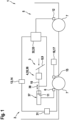
- a motor vehicle 1, as exemplified in Figure 1 is shown in a highly simplified and circuit diagram-like manner, has a braking system 2.
- the braking system 2 comprises a service braking device 3, a brake transmission device 4 and a parking braking device 5.
- the Service brake device 3 serves to brake the motor vehicle 1 while driving.
- the service brake device 3 has at least one brake 6, also referred to below as service brake 6, which acts on at least one wheel 7 of the motor vehicle 1.
- two wheels 7 of the motor vehicle 1 are visible, wherein purely by way of example a single service brake 6 is shown which acts on an associated one of the wheels 7 when the service brake device 3 is actuated in order to brake the motor vehicle 1.
- an output rod 10 of the brake transmission device 4 cooperates with the at least one service brake 6.
- the brake transmission device 4 is, for example, a brake booster 35, in particular an electromechanical brake booster 35, or an external power brake 36.
- the brake transmission device 4 is coupled to an actuator 8 which, when actuated, can lead to an adjustment of the output rod 10.
- the actuator 8 is a brake pedal 9 which is actuated by a user (not shown), as indicated by an arrow.
- the at least one service brake 6 of the exemplary embodiment shown is hydraulically operated. For this purpose, the service brake 6 is acted upon with a brake fluid stored in a cylinder 37 to exert a braking force.
- a piston 11 is guided in the cylinder 37 to act upon the brake fluid.
- the output rod 10 is connected to the piston 11, so that the adjustment of the output rod along a Figure 1 indicated adjustment path 38 leads to a movement of the piston 11 in the cylinder 37.
- the piston 11 presses the brake fluid with a pressure corresponding to the braking force in the direction of the service brake 6, this pressure being known to the expert as the brake pressure.
- the force exerted by the service brake 6 Braking force is therefore dependent on the adjustment path.
- the brake pressure can be determined in particular if the adjustment path, the dimensions of the piston 11, the cylinder 37 and the corresponding volumes are known. With the brake pressure and thus the braking force, a deceleration, i.e. a negative acceleration, of the motor vehicle 1 can also be determined with knowledge of the conditions of the motor vehicle 1.
- the parking brake device 5 serves the purpose of securing the motor vehicle 1, in particular in a parking position, against movement, for example rolling away.
- the parking brake device 5 blocks at least one wheel 7 of the motor vehicle 1 for this purpose.
- the parking brake device 5 has at least one brake 12, which is also referred to below as parking brake 12 and is also known to the person skilled in the art as parking brake 12.
- the at least one parking brake 12 blocks at least one wheel 7 of the motor vehicle 1 in an activated state.
- Figure 1 In the embodiment shown, a parking brake 12 of the parking brake device 5 can be seen purely by way of example, wherein the parking brake 12 interacts purely by way of example and for the sake of clarity with the wheel 7 which is different from the service brake 6.
- the parking brake 12 at least partially corresponds to the service brake 6.
- the parking brake device 5 has a triggering device 13 which can, for example, have a button 14 which can be manually operated by a user (not shown). If the triggering device 13, in the embodiment shown in particular the button 14, is operated and the motor vehicle 1 is stationary, the at least one parking brake 6 is activated.
- a wheel speed measuring device 15 is used in normal operation, which enables the detection of the speed of at least one wheel 7 of the motor vehicle 1.
- the data determined by the wheel speed measuring device 15 are evaluated in an associated control unit 16, which is in particular an ESP control unit 17 of the motor vehicle 1, and thus the current speed of the motor vehicle 1 and consequently also a standstill of the motor vehicle 1 are determined.
- the following procedure is used to activate the at least one parking brake 6.
- a maximum possible speed of the motor vehicle 1 is used.
- the adjustment path 38 of the brake transmission device 4 is used to determine the deceleration of the motor vehicle 1 exerted by the at least one service brake 6, which is a negative acceleration of the motor vehicle 1.
- the maximum possible speed can, for example, be the maximum permissible speed of the motor vehicle 1.
- the maximum possible speed can be an estimate based on the speed at an initial time 0, wherein accelerations of the motor vehicle 1, for example by a drive device 31 of the motor vehicle 1, and/or a gradient can be taken into account.
- the initial time can, for example, be the time of failure of the wheel speed measuring device 15 and/or the control unit 16.
- the initial time can be a known standstill of the motor vehicle 1, for example an activated state of the parking brake device 5.
- the deceleration of the motor vehicle 1 is determined depending on the adjustment path 38.
- the actuation time it is then determined whether the motor vehicle 1 is stationary at the time the triggering device 13 is actuated, hereinafter also referred to as the actuation time. If this is the case, the at least one parking brake 6 is activated so that at least one wheel 7 of the motor vehicle 1 is blocked. If no standstill is determined at the time of actuation, the activation of the at least one parking brake 6 can be delayed until a standstill is detected. In this case, a deceleration of the motor vehicle 1, in particular an additional deceleration, can be actively carried out and/or a user can be prompted to carry out such a deceleration.
- the standstill of the motor vehicle 1 can be determined by determining a duration required for the deceleration and its period of time starting from the maximum possible speed until the motor vehicle 1 comes to a standstill.
- the standstill can be determined alternatively or additionally by determining a current speed of the motor vehicle 1 during the deceleration and its period of time starting from the maximum possible speed.
- the method described above for activating the parking brake device 5 can be carried out in particular according to the Figure 2 flow chart shown, whereby in the embodiment shown the determined current speed is used to determine of the standstill of the motor vehicle 1. It is further assumed that the speed at the initial time 0 is known.
- the method is initiated at the initial time 0 with a known speed.
- the known speed is set as the current speed of the motor vehicle 1 in a procedural measure 18, hereinafter also referred to as speed measure 18.
- a maximum possible speed of the motor vehicle 1 is estimated in a procedural measure 19, hereinafter also referred to as maximization measure 19, taking into account a maximum possible acceleration of the motor vehicle 1.
- a subsequent procedural measure 20, hereinafter also referred to as comparison measure 20 a comparison is made as to whether the maximum possible speed estimated in the maximization measure 19 is zero, i.e. whether the motor vehicle 1 is stationary. If this is the case, i.e. the estimated maximum possible speed is zero, it is deemed that the motor vehicle 1 is stationary.
- the state of the triggering device 13 is queried. If the triggering device 13 is actuated, the activation of the at least one parking brake 12 takes place in a subsequent procedural measure 22, which is also referred to below as the activation measure 22. The at least one parking brake 12 is therefore activated if the triggering device 13 is actuated and the determined current speed is zero.
- the result in the comparison measure 20 is a current speed that deviates from zero, i.e. if the motor vehicle 1 is not stationary according to the determined current speed, the state of the triggering device 13 is queried in a procedural measure 23, i.e. whether the triggering device 13 is activated.
- This procedural measure 23 is therefore also a query measure 23 and is referred to below as the second query measure 23 to better distinguish it from the first query measure 21. If the second query measure 21 shows that the triggering device 13 has not been activated, the deceleration and the resulting, then current speed are subsequently determined.
- the adjustment path of the input rod 10 is determined and/or queried in a process measure 24.
- the brake pressure is determined based on the adjustment path of the input rod 10.
- the adjustment path is converted into the brake pressure.
- the deceleration of the motor vehicle 1 achieved with the brake pressure is determined based on the brake pressure.
- the time period of the deceleration is determined or queried in a process measure 27.
- the following, now current speed v is determined in a subsequent process measure 28, hereinafter also referred to as update measure 28, based on the speed determined in comparison measure 18 based on the deceleration and the time period.
- update measure 28 the current speed is therefore updated.
- the process then returns to speed measure 18 with the current speed determined in update measure 26. where speed measure 18 replaces the previously determined current speed determined in update measure 26, i.e. the speed at the initial time in the first iteration.
- the input rod 10 can be adjusted by a predetermined adjustment path in a process measure 29.
- This process measure 29 can therefore also be referred to as an active service brake measure 29.
- the process then goes to process measure 24, whereby the predetermined adjustment of the input rod 10 carried out in the service brake measure 29 is taken into account accordingly.
- FIG 2 it is possible to check in a procedural measure 30 before carrying out the service braking measure 29 whether an adjustment of the input rod 10 has already taken place, and to only carry out the service braking measure 29 if the result of the check in the procedural measure 30 is above a predetermined value, i.e. only if the adjustment path is smaller than a predetermined value.
- the method according to the invention is implemented using a correspondingly designed control device 32. This can be done using a computer program product stored in the control device 32.
- the control device 32 is preferably separate from the control unit 16.
- the control device 32 is in particular a main control unit 33 of the motor vehicle 1.
- the control device 32 is appropriately communicative with the at least one parking brake 12, the triggering device 13, the brake transmission device 4 and the drive device 31.
Landscapes
- Engineering & Computer Science (AREA)
- Mechanical Engineering (AREA)
- Transportation (AREA)
- Human Computer Interaction (AREA)
- Regulating Braking Force (AREA)
- Braking Systems And Boosters (AREA)
- Valves And Accessory Devices For Braking Systems (AREA)
Description
- Die vorliegende Erfindung betrifft ein Verfahren nach dem unabhängigen Anspruch 1 zum Betreiben eines Bremssystems eines Kraftfahrzeugs, wobei das Bremssystem eine Bremsübertragungseinrichtung sowie eine elektrische Parkbremseinrichtung aufweist. Die Erfindung betrifft des Weiteren ein Kraftfahrzeug mit einem derart betriebenen Bremssystem nach dem Anspruch 9.
- Kraftfahrzeuge weisen üblicherweise ein Bremssystem auf, welches dem Bremsen während der Fahrt sowie als sogenannte Parkbremse dient. Zum Bremsen während der Fahrt umfasst das Bremssystem in der Regel eine Bremse, welche nachfolgend auch als Betriebsbremse bezeichnet wird. Die Parkbremsfunktion wird in der Regel über eine zugehörige Parkbremseinrichtung des Bremssystems erzielt. Die Parkbremseinrichtung weist zu diesem Zweck wenigstens eine Parkbremse auf. Die Aktivierung der Parkbremse, auch als Feststellen der Parkbremse bekannt, setzt üblicherweise einen Trigger voraus, der über eine Auslöseeinrichtung erfolgt. Die Auslöseeinrichtung kann zu diesem Zweck einen von einem Benutzer manuell betätigbaren Taster aufweisen. Mit der Parkbremseinrichtung erfolgt eine Sicherung des Kraftfahrzeugs, sodass, insbesondere in einer Parkposition, ein Rollen des Kraftfahrzeugs verhindert ist. Zu diesem Zweck wird mit der zumindest einen Parkbremse zumindest ein Rad des Kraftfahrzeugs blockierend gebremst. Aus Sicherheitsgründen ist die Aktivierung der Parkbremseinrichtung und somit das blockierende Bremsen zumindest eines Rades des Kraftfahrzeugs lediglich dann durchzuführen, wenn das Kraftfahrzeug stillsteht. Zu diesem Zweck greifen aus dem Stand der Technik bekannte Parkbremseinrichtungen auf Raddrehzahlmesser des Kraftfahrzeugs zurück. Die Auswertung der von Raddrehzahlmessern gelieferten Daten erfolgen üblicherweise in einem Steuergerät, in der Regel in einem ESP-Steuergerät, des Kraftfahrzeugs, um eine Geschwindigkeit des Kraftfahrzeugs zu ermitteln und somit auch einen Stillstand des Kraftfahrzeugs festzustellen. Erst wenn die von den Raddrehzahlmessern gelieferten Daten auf einen Stillstand des Kraftfahrzeugs schließen lassen, erfolgt eine Aktivierung der Parkbremseinrichtung, auch wenn die Auslöseeinrichtung bereits zuvor betätigt wurde.
- Als Stand der Technik können die folgenden Dokumente erwähnt werden :
DE 10 2019 200827 A1 ,EP 2 055 541 A1 ,DE 10 2012 212329 A1 undWO 89/01887 A1 - Hierbei ergibt sich das Problem, dass bei einem Ausfall der Raddrehzahlmesser und/oder oder des die Daten der Raddrehzahlmesser auswertenden Steuergeräts, insbesondere des ESP-Steuergerät, eine Aktivierung der Parkbremseinrichtung ausgesetzt wird. Somit soll verhindert werden, dass die Parkbremseinrichtung während der Fahrt des Kraftfahrzeugs aktiviert wird. Dies führt zu einer reduzierten bis hin zur fehlenden Verfügbarkeit der Parkbremseinrichtung. Darüber hinaus kann das Kraftfahrzeug in der Folge auch bei einer notwendigen und/oder erwünschten Aktivierung der Parkbremseinrichtung, beispielsweise beim Parken des Kraftfahrzeugs, rollen und sich somit bewegen.
- Die vorliegende Erfindung beschäftigt sich daher mit der Aufgabe, für ein Verfahren zum Betreiben eines Bremssystems eines Kraftfahrzeugs der vorstehend genannten Art sowie für ein solches Kraftfahrzeug verbesserte oder zumindest andere Ausführungsformen anzugeben, welche sich insbesondere durch eine erhöhte Sicherheit bei zugleich einfacher Umsetzung auszeichnen.
- Diese Aufgabe wird erfindungsgemäß durch die Gegenstände der unabhängigen Ansprüche gelöst. Vorteilhafte Ausführungsformen sind Gegenstand der abhängigen Ansprüche.
- Die vorliegende Erfindung beruht auf dem allgemeinen Gedanken, insbesondere bei einem Ausfall einer mithilfe von Raddrehzahlen eines Kraftfahrzeugs erfolgten Stillstanderkennung des Kraftfahrzeugs, zum Aktivieren einer Parkbremseinrichtung eine mittels einer Bremsübertragungseinrichtung ausgeübte Bremskraft sowie die daraus resultierende Verzögerung, also negative Beschleunigung, des Kraftfahrzeugs und eine maximal mögliche Geschwindigkeit des Kraftfahrzeugs heranzuziehen, um zu ermitteln, ob das Kraftfahrzeug unter Berücksichtigung der maximal möglichen Geschwindigkeit sowie der Verzögerung und der Zeitspanne der Verzögerung still steht, wobei die Parkbremseinrichtung erst dann aktiviert wird, wenn zum Zeitpunkt des Auslösens der Parkbremsfunktion ein Stillstand des Kraftfahrzeugs ermittelt wurde. Somit ist es auf einfache und zuverlässige Weise möglich, auch bei mangelnden Informationen über Raddrehzahlen des Kraftfahrzeugs und/oder beim Ausfall der Auswertung von Raddrehzahlen des Kraftfahrzeugs, beispielsweise eines ESP-Steuergeräts, die Parkbremseinrichtung bei einem Stillstand des Kraftfahrzeugs zu aktivieren. In der Folge ist die Sicherheit und Verfügbarkeit bei zugleich einfacher und kostengünstiger Umsetzung erhöht.
- Der erfindungsgemäße Gedanke wird in einem Verfahren zum Betreiben eines Bremssystems eines Kraftfahrzeugs umgesetzt. Das Bremssystem umfasst eine Betriebsbremseinrichtung, die Bremsübertragungseinrichtung und die Parkbremseinrichtung. Die Betriebsbremseinrichtung weist zumindest eine Betriebsbremse auf, welche dem Bremsen des Kraftfahrzeugs bei der Fahrt dient. Die Bremsübertragungseinrichtung weist eine Ausgangsstange auf, welche mit der zumindest einen Betriebsbremse derart verbunden ist, das mittels der Ausgangsstange eine Bremskraft zum Bremsen auf die zumindest eine Betriebsbremse übertragen wird. Die Parkbremseinrichtung weist zum Feststellen des Kraftfahrzeugs zumindest eine Parkbremse auf. Die Parkbremseinrichtung weist ferner eine Auslöseeinrichtung zum Aktivieren der zumindest einen Parkbremse auf. Erfindungsgemäß werden zum Ermitteln des Stillstands des Kraftfahrzeugs ein Verstellweg der Ausgangsstange sowie eine maximal mögliche Geschwindigkeit des Kraftfahrzeugs herangezogen. Dabei wird abhängig des Verstellwegs eine mit der zumindest einen Betriebsbremse ausgeübte Verzögerung des Kraftfahrzeugs ermittelt und ausgehend von der maximal möglichen Geschwindigkeit unter Berücksichtigung der Zeitspanne der Verzögerung ermittelt, ob das Kraftfahrzeug bei der Betätigung der Auslöseeinrichtung still steht. Es wird also ermittelt, ob das Kraftfahrzeug zu einem Zeitpunkt der Betätigung der Auslöseeinrichtung, nachfolgend auch Betätigungszeitpunkt genannt, stillsteht. Dabei wird die zumindest eine Parkbremse aktiviert, wenn zum Betätigungszeitpunkt ein Stillstand ermittelt ist.
- Das erfindungsgemäße Verfahren kommt zweckmäßig dann zum Einsatz, wenn Daten einer Raddrehzahlmesseinrichtung zur Messung der Drehzahl zumindest eines Rads des Kraftfahrzeugs nicht zur Verfügung stehen, weil beispielsweise die Raddrehzahlmesseinrichtung ausfällt, und/oder wenn eine Auswertung der Daten der Raddrehzahlmesseinrichtung nicht möglich ist, insbesondere, wenn eine die Daten auswertende Einrichtung beschädigt ist oder ausfällt. Eine derartige, die Daten auswertende Einrichtung ist insbesondere ein Steuergerät, beispielsweise ein ESP-Steuergerät, des Kraftfahrzeugs. Folglich kommt das erfindungsgemäße Verfahren insbesondere dann zum Einsatz, wenn das ESP-Steuergerät beschädigt und/oder ausgefallen ist. Das erfindungsgemäße Verfahren erlaubt somit die Nutzung der Parkbremseinrichtung auch bei einem Ausfall des ESP-Steuergeräts.
- Dementsprechend erfolgen die genannten Ermittlungen und/oder das Heranziehen der maximalen Geschwindigkeit zweckmäßig unabhängig von einer Raddrehzahlmessung.
- Die maximal mögliche Geschwindigkeit des Kraftfahrzeugs ist zweckmäßig diejenige Geschwindigkeit, welche das Kraftfahrzeug bis zum Zeitpunkt der ansetzenden Verzögerung maximal erreichen kann.
- Als maximal mögliche Geschwindigkeit kann prinzipiell die maximal zulässige Geschwindigkeit des Kraftfahrzeugs herangezogen werden.
- Alternativ kann zum Heranziehen der maximal möglichen Geschwindigkeit eine zuletzt bekannte Geschwindigkeit des Kraftfahrzeugs berücksichtigt werden. Bei der maximal möglichen Geschwindigkeit wird also in diesem Fall eine zu einem Initialzeitpunkt bekannte Geschwindigkeit des Kraftfahrzeugs berücksichtigt.
- Der Initialzeitpunkt kann der Zeitpunkt eines Ausfalls der Raddrehzahlmesseinrichtung des Kraftfahrzeugs sein. Alternativ oder zusätzlich kann der Initialzeitpunkt der Zeitpunkt eines Ausfalls eines ESP-Steuergeräts des Kraftfahrzeugs sein. Insbesondere kann hierdurch das erfindungsgemäße Verfahren ausgelöst und durchgeführt werden.
- Vorstellbar ist es auch, als Initialzeitpunkt den Zeitpunkt eines Stillstands des Kraftfahrzeugs und somit der Geschwindigkeit von null zu verwenden. Dies kann beispielsweise bei einer letztmaligen Aktivierung der zumindest einen Parkbremse und/oder beim erstmaligen Anfahren nach der letztmaligen Aktivierung der zumindest einen Parkbremse gegeben sein.
- Das Heranziehen der maximalen Geschwindigkeit kann insbesondere durch eine Abschätzung der maximal möglichen Geschwindigkeit ausgehend von der Geschwindigkeit zum Initialzeitpunkt erfolgen. Hierzu ist es insbesondere vorstellbar, eine mit dem Kraftfahrzeug maximal mögliche Beschleunigung, beispielsweise durch eine Antriebseinrichtung des Kraftfahrzeugs zu berücksichtigen. Mit anderen Worten, beim Heranziehen der maximalen Geschwindigkeit kann angenommen werden, dass das Kraftfahrzeug mit den vorhandenen Mitteln, insbesondere mit der vorhandenen Antriebseinrichtung, mit maximaler Leistung beschleunigt wird. Alternativ oder zusätzlich kann hierbei ein Gefälle während der Fahrt berücksichtigt werden. Ebenso ist es vorstellbar, gegebenenfalls vorhandene Koordinaten des Kraftfahrzeugs und deren Änderung, also insbesondere GPS-Daten und deren Änderung, zum Heranziehen der maximalen Geschwindigkeit zu berücksichtigen.
- Wie vorstehend erläutert, erfolgen die erfindungsgemäßen Schritte unter Berücksichtigung der Betätigung der Auslöseeinrichtung. Dies hat insbesondere zur Folge, dass eine Aktivierung der zumindest einen Parkbremse vorteilhaft ohne eine Betätigung der Auslöseeinrichtung nicht erfolgt. Mit anderen Worten, eine Aktivierung der zumindest einen Parkbremse bleibt vorteilhaft ohne Betätigung der Auslöseeinrichtung aus.
- Die Übertragungseinrichtung kann als ein Bremskraftverstärker und/oder als eine Fremdkraftbremse ausgestaltet sein.
- Der Bremskraftverstärkerkann prinzipiell beliebig ausgestaltet sein. Vorstellbar sind beispielsweise Vakuum betriebene Bremskraftverstärker. Der Bremskraftverstärker kann insbesondere zumindest teilweise elektrisch, vorteilhaft elektromechanisch, betrieben sein. Die Bremsübertragungseinrichtung kann mit einem Betätiger gekoppelt sein, sodass eine Betätigung des Betätigers zu einer Verstellung der Ausgangsstange und somit einer Änderung des Verstellwegs führen kann.
- Der Betätiger ist üblicherweise von einem Benutzer, also insbesondere einem Fahrzugführer, manuell betätigt, um das Kraftfahrzeug während der Fahrt zu bremsen. Der Betätiger ist insbesondere ein Bremspedal und dergleichen.
- Bei zumindest teilautonom fahrenden Kraftfahrzeugen kann der Betätiger auch autonom über eine Steuereinrichtung des Kraftfahrzeugs betätigt werden.
- Zumindest eine der wenigstens einen Parkbremse kann wenigstens teilweise einer der wenigstens einen Betriebsbremsen entsprechen.
- Ist die zumindest eine Parkbremse aktiviert, so blockiert es zumindest ein Rad des Kraftfahrzeugs, stellt dieses also fest. Die Parkbremse ist dem Fachmann daher auch als "Feststellbremse" bekannt. Das Blockieren des zumindest einen Rads erfolgt hierbei zweckmäßig bis zum Deaktivieren der zumindest einen Parkbremse. Das Deaktivieren kann ebenfalls über die Auslöseeinrichtung erfolgen.
- Die Auslöseeinrichtung dient als Trigger zum Aktivieren der zumindest einen Parkbremse. Die Aktivierung der zumindest einen Parkbremse wird also erst dann ausgelöst, wenn die Auslöseeinrichtung betätigt wird. Die Betätigung der Auslöseeinrichtung erfolgt üblicherweise durch den Benutzer des Kraftfahrzeugs. Die Auslöseeinrichtung kann einen Taster aufweisen und/oder beim Verstellen einer Schaltung des Kraftfahrzeugs in die "Parkstellung" betätigt sein und/oder beim Verstellen einer Zündung des Kraftfahrzeugs in eine "Aus" Stellung betätigt sein.
- Bei zumindest teilautonom fahrenden Kraftfahrzeugen kann die Auslöseeinrichtung auch autonom über eine Steuereinrichtung des Kraftfahrzeugs betätigt werden.
- Das Bestimmen der Verzögerung über den Verstellweg erfolgt vorteilhaft über das Ermitteln der mittels der Bremsübertragungseinrichtung ausgeübten Bremskraft. Es wird also die Bremskraft ermittelt und/oder die bereits in der Bremsübertragungseinrichtung ermittelte Bremskraft herangezogen. Die mittels der Bremsübertragungseinrichtung auf die zumindest eine Betriebsbremse übertragene Bremskraft ist hierbei abhängig vom Verstellweg, wobei zweckmäßig größere Verstellwege eine höhere Bremskraft zur Folge haben und umgekehrt. Da der Verstellweg eine in der Bremsübertragungseinrichtung relevante Größe ist, die zweckmäßig ohnehin in der Bremsübertragungseinrichtung hinterlegt ist und/oder vorliegt, kann auf diese Weise auf den ohnehin bekannten Verstellweg zum Ermitteln der Verzögerung zurückgegriffen werden. Das Verfahren und dessen Umsetzung werden auf diese Weise vereinfacht.
- Vorteilhaft ist die zumindest eine Betriebsbremse mit einem Fluid betätigt. Dabei erfolgt die Ermittlung der Verzögerung bevorzugt auf Basis des mit dem Fluid ausgebübten Drucks, dem Fachmann auch als Bremsdruck bekannt. Bevorzugt wird über die Ausgangsstange ein Kolben in einem Volumen mit einem Bremsfluid bewegt und somit der Druck im Fluid erzeugt. Hierbei kann insbesondere aufgrund der gegebenen Dimensionen des Kolbens und des Volumens der Bremsdruck ermittelt werden. Bevorzugt ist die zumindest eine Betriebsbremse hydraulisch, insbesondere mit einer Bremsflüssigkeit, betätigt.
- Es versteht sich, dass zeitliche Änderungen des Verstellwegs und somit der Bremskraft bei der Ermittlung der Verzögerung berücksichtigt werden. Mit anderen Worten, unter Verstellweg und Bremskraft sind vorliegend entsprechende zeitliche Verläufe des Verstellwegs und der Bremskraft zu verstehen. Dies führt dazu, dass jeweils auch der zeitliche Verlauf der Verzögerung ermittelt und berücksichtigt wird. Als Beispiel sei hierbei auf einen Bremsvorgang mit unterschiedlichen Verstellwegen hingewiesen. Beispielsweise kann die zumindest eine Betriebsbremse zunächst mit einer ersten Bremskraft und dann mit einer zweiten Bremskraft betätigt werden. Hierbei wird für die jeweilige Bremskraft und deren Zeitspanne eine zugehörige Verzögerung berücksichtigt. Mit anderen Worten, bei einem mehrstufigen Bremsvorgang wird für die jeweilige Bremsstufe eine zugehörige Verzögerung ermittelt und mit der jeweils zugehörigen Zeitspanne beim Ermitteln des Stillstands des Kraftfahrzeus berücksichtigt.
- Es versteht sich ferner, dass das Heranziehen der maximalen Geschwindigkeit mögliche Erhöhungen der maximalen Geschwindigkeit berücksichtigt. Erfolgt also beispielsweise vor dem Stillstand des Kraftfahrzeugs eine Beschleunigung des Kraftfahrzeugs, führt dies zu einer entsprechenden Erhöhung der maximalen möglichen Geschwindigkeit, sodass im Ergebnis ein Verlauf der maximal möglichen Geschwindigkeit berücksichtigt wird.
- Die Ermittlung des Stillstands des Kraftfahrzeugs kann durch das Ermitteln einer sich aus der Verzögerung und deren Zeitspanne ausgehend von der maximal möglichen Geschwindigkeit ergebenen aktuellen Geschwindigkeit des Kraftfahrzeugs erfolgen. Es wird also ermittelt, ob die ermittelte aktuelle Geschwindigkeit zum Betätigungszeitpunkt der Auslöseeinrichtung einen Stillstand des Kraftfahrzeugs bedeutet. Dies ist insbesondere dann der Fall, wenn die ermittelte aktuelle Geschwindigkeit zum Betätigungszeitpunkt null beträgt. Die zumindest eine Parkbremse wird also dann aktiviert, wenn die ermittelte aktuelle Geschwindigkeit einen Stillstand des Kraftfahrzeugs bedeutet.
- Alternativ kann zur Ermittlung des Stillstands des Kraftfahrzeugs die zeitliche Dauer ermittelt werden, bei welcher das Kraftfahrzeug ausgehend von der maximal möglichen Geschwindigkeit unter Berücksichtigung der Verzögerung sowie deren Zeitspanne stillsteht. Erfolgt die Betätigung der Auslöseeinrichtung mit dem Ablauf der Dauer oder danach, wird die zumindest eine Parkbremse aktiviert. Dies kann derart erfolgen, dass die Parkbremseinrichtung aktiviert wird, wenn eine Differenz zwischen dem Betätigungszeitpunkt und dem Initialzeitpunkt größer ist als die Dauer.
- Selbstverständlich können zum Ermitteln des Stillstands auch sowohl die aktuelle Geschwindigkeit als auch die Dauer berücksichtigt werden.
- Wie vorstehend erwähnt, werden jeweils entsprechende Verläufe, insbesondere der Verzögerung und der maximal möglichen Geschwindigkeit berücksichtigt. Dies kann dadurch umgesetzt sein, dass die aktuelle Geschwindigkeit und/oder die Dauer iterativ ermittelt werden.
- Ist die Auslöseeinrichtung betätigt bevor ein Stillstand des Kraftfahrzeugs ermittelt wurde, also beispielsweise die ermittelte Geschwindigkeit zum Betätigungszeitpunkt ungleich null und/oder die die Differenz zwischen dem Betätigungszeitpunkt und dem Initialzeitpunkt kleiner als die Dauer, bleibt eine Aktivierung der zumindest einen Parkbremse zweckmäßig aus. Dabei kann die Aktivierung hinausgezögert werden, bis ein Stillstand ermittelt ist. Mit anderen Worten, die zumindest eine Parkbremse wird erst dann aktiviert, wenn ein Stillstand des Kraftfahrzeugs ermittelt ist.
- Bei einer Betätigung der Auslöseeinrichtung vor einem ermittelten Stillstand des Kraftfahrzeugs kann eine Verzögerung, insbesondere eine zusätzliche Verzögerung, des Kraftfahrzeugs durchgeführt und die zumindest eine Parkbremse erst dann aktiviert werden, wenn ein Stillstand des Kraftfahrzeugs ermittelt ist. Somit wird die Dauer des Hinauszögerns der Aktivierung der zumindest einen Parkbremse reduziert.
- Bevorzugt wird dabei die zumindest eine Betriebsbremse mit einer vorgegebenen Bremskraft betätigt und die zumindest eine Parkbremse aktiviert, wenn ein Stillstand des Kraftfahrzeugs ermittelt ist.
- Bei einer Betätigung der Auslöseeinrichtung vor einem ermittelten Stillstand des Kraftfahrzeugs kann alternativ oder zusätzlich eine Meldung mit einer Aufforderung an einen Benutzer ausgegeben werden, die Auslöseeinrichtung weiterhin zu betätigen. Bevorzugt ist es dabei, wenn das Kraftfahrzeug während der Betätigung der Auslöseeinrichtung, insbesondere zusätzlich, vorzugsweise mit der genannten, vorgegebenen Bremskraft verzögert wird, bis der Stillstand ermittelt ist.
- Es versteht sich, dass neben dem Verfahren auch ein Kraftfahrzeug mit einem derart betriebenen Bremssystem zum Umfang dieser Erfindung gehört. Dabei sind die betroffenen Bestandteile des Kraftfahrzeugs entsprechend ausgestaltet.
- Zum Durchführen des Verfahrens kann das Kraftfahrzeug eine entsprechend ausgestaltete Steuereinrichtung aufweisen. Vorstellbar ist es insbesondere, das erfindungsgemäße Verfahren als ein Computerprogrammprodukt in der Steuereinrichtung zu hinterlegen.
- Die Steuereinrichtung kann Bestandsteil des ESP-Steuergeräts sein oder diesem entsprechen.
- Denkbar sind auch Ausführungsformen, bei denen die Steuereinrichtung vom ESP-Steuergerät separat ist. Somit ist auch bei einem möglichen Ausfall des ESP-Steuergeräts die Parkbremsfunktion weiterhin möglich und somit die Verfügbarkeit weiter erhöht. Bei der Steuereinrichtung handelt es sich insbesondere um ein Hauptsteuergerät des Kraftfahrzeugs. Das Hauptsteuergerät kann hierbei insbesondere auch dem Steuern einer Antriebseinrichtung des Kraftfahrzeugs dienen. Ebenso kann die Steuereinrichtung ein Steuergerät der Bremsübertragungseinrichtung sein.
- Weitere wichtige Merkmale und Vorteile der Erfindung ergeben sich aus den Unteransprüchen, aus den Zeichnungen und aus der zugehörigen Figurenbeschreibung anhand der Zeichnungen.
- Es versteht sich, dass die vorstehend genannten und die nachstehend noch zu erläuternden Merkmale nicht nur in der jeweils angegebenen Kombination, sondern auch in anderen Kombinationen oder in Alleinstellung verwendbar sind, ohne den Rahmen der vorliegenden Erfindung zu verlassen.
- Bevorzugte Ausführungsbeispiele der Erfindung sind in den Zeichnungen dargestellt und werden in der nachfolgenden Beschreibung näher erläutert, wobei sich gleiche Bezugszeichen auf gleiche oder ähnliche oder funktional gleiche Komponenten beziehen.
- Es zeigen
-
Figur 1 eine schematisch, stark vereinfachte und schaltplanartige Darstellung eines Kraftfahrzeugs mit einem Bremssystem, -
Figur 2 ein Flussdiagramm zur Erläuterung eines Verfahrens zum Betreiben des Bremssystems. - Ein Kraftfahrzeug 1, wie es beispielhaft in
Figur 1 stark vereinfacht und schaltplanartige dargestellt ist, weist ein Bremssystem 2 auf. Das Bremssystem 2 umfasst eine Betriebsbremseinrichtung 3, eine Bremsübertragungseinrichtung 4 sowie eine Parkbremseinrichtung 5. Die Betriebsbremseinrichtung 3 dient dem Bremsen des Kraftfahrzeugs 1 während der Fahrt. Zu diesem Zweck weist die Betriebsbremseinrichtung 3 zumindest eine nachfolgend auch als Betriebsbremse 6 bezeichnete Bremse 6 auf, welche auf zumindest ein Rad 7 des Kraftfahrzeugs 1 einwirkt. InFigur 1 sind hierbei rein beispielhaft zwei Räder 7 des Kraftfahrzeugs 1 sichtbar, wobei rein beispielhaft eine einzige Betriebsbremse 6 dargestellt ist, welche beim Betätigen der Betriebsbremseinrichtung 3 auf ein zugehöriges der Räder 7 einwirkt, um das Kraftfahrzeug 1 zu bremsen. Zum Ausüben einer Bremskraft wirkt eine Ausgangsstange 10 der Bremsübertragungseinrichtung 4 mit der zumindest einen Betriebsbremse 6 zusammen. Die Bremsübertragungseinrichtung 4 ist beispielsweise ein Bremskraftverstärker 35, insbesondere ein elektromechanischer Bremsverstärker 35, oder eine Fremdkraftbremse 36. In dem gezeigten Ausführungsbeispiel ist die Bremsübertragungseinrichtung 4 mit einen Betätiger 8 gekoppelt, der bei einer Betätigung zu einem Verstellen der die Ausgansstange 10 führen kann In dem gezeigten Ausführungsbeispielen ist der Betätiger 8 ein Bremspedal 9, welches von einem nicht gezeigten Benutzer, wie mit einem Pfeil angedeutet, betätigt wird. Die zumindest eine Betriebsbremse 6 des gezeigten Ausführungsbeispiels ist hydraulisch betrieben. Zu diesem Zweck wird die Betriebsbremse 6 zum Ausüben einer Bremskraft mit einem in einem Zylinder 37 bevorrateten Bremsflüssigkeit beaufschlagt. Zum Beaufschlagen mit der Bremsflüssigkeit ist im gezeigten Ausführungsbeispiel ein Kolben 11 im Zylinder 37 geführt. Hierbei ist die Ausgangsstange 10 mit dem Kolben 11 verbunden, sodass das Verstellen der Ausgangsstange entlang eines inFigur 1 angedeuteten Verstellwegs 38 zu einer Bewegung des Kolbens 11 im Zylinder 37 führt. Der Kolben 11 presst zum Bremsen die Bremsflüssigkeit mit einem der Bremskraft entsprechenden Druck in Richtung der Betriebsbremse 6, wobei dieser Druck dem Fachmann als Bremsdruck bekannt ist. Die mit der Betriebsbremse 6 ausgeübte Bremskraft ist also vom Verstellweg abhängig. Insbesondere bei Kenntnis des Verstellwegs, der Dimensionierung des Kolbens 11, des Zylinders 37sowie der entsprechenden Volumen in der kann der Bremsdruck ermittelt werden. Mit dem Bremsdruck und somit der Bremskraft kann ferner mit Kenntnis der Gegebenheiten des Kraftfahrzeugs 1 eine Verzögerung, also eine negative Beschleunigung, des Kraftfahrzeugs 1 ermittelt werden. - Die Parkbremseinrichtung 5 dient dem Zweck, das Kraftfahrzeug 1, insbesondere in einer Parkposition, gegenüber einer Bewegung, beispielsweise einem Wegrollen, zu sichern. Die Parkbremseinrichtung 5 blockiert zu diesem Zweck zumindest ein Rad 7 des Kraftfahrzeugs 1. Zu diesem Zweck weist die Parkbremseinrichtung 5 zumindest eine Bremse 12 auf, welche nachfolgend auch als Parkbremse 12 bezeichnet wird und dem Fachmann auch als Feststellbremse 12 bekannt ist. Die zumindest eine Parkbremse 12 blockiert in einem aktivierten Zustand zumindest ein Rad 7 des Kraftfahrzeugs 1. Beim in
Figur 1 gezeigten Ausführungsbeispiel ist rein beispielhaft eine Parkbremse 12 der Parkbremseinrichtung 5 zu sehen, wobei die Parkbremse 12 rein beispielhaft und zur besseren Darstellung mit dem vom der Betriebsbremse 6 unterschiedlichen Rad 7 zusammenwirkt. Vorstellbar sind aber auch Ausführungsformen, bei denen die Parkbremse 12 zumindest teilweise der Betriebsbremse 6 entspricht. Zum Aktivieren der zumindest einen Parkbremse 6 weist die Parkbremseinrichtung 5 eine Auslöseeinrichtung 13 auf, welche beispielsweise einen Taster 14 aufweisen kann, der von einem nicht gezeigten Benutzer manuell betätigt werden kann. Ist die Auslöseeinrichtung 13, im gezeigten Ausführungsbeispiel also insbesondere der Taster 14, betätigt und steht das Kraftfahrzeug 1 still, wird die zumindest eine Parkbremse 6 aktiviert. Zur Erkennung eines Stillstands des Kraftfahrzeugs 1 kommt in einem normalen Betrieb eine Raddrehzahlenmesseinrichtung 15 zum Einsatz, welche das Detektieren der Drehzahl zumindest eines Rads 7 des Kraftfahrzeugs 1 ermöglicht. Die von der Raddrehzahlenmesseinrichtung 15 ermittelten Daten werden in einem zugehörigen Steuergerät 16, das insbesondere ein ESP-Steuergerät 17 des Kraftfahrzeugs 1 ist, ausgewertet und somit die aktuelle Geschwindigkeit des Kraftfahrzeugs 1 und folglich auch ein Stillstand des Kraftfahrzeugs 1 bestimmt. - Insbesondere wenn eine derartige Bestimmung des Stillstands des Kraftfahrzeugs 1 nicht möglich ist, beispielsweise wenn die Raddrehzahlmesseinrichtung 15 und/oder das Steuergerät 16 beschädigt und/oder ausgefallen sind, wird zum Aktivieren der zumindest einen Parkbremse 6 wie folgt verfahren.
- Es wird eine maximal mögliche Geschwindigkeit des Kraftfahrzeugs 1 herangezogen. Zudem wird der Verstellweg 38 der Bremsübertragungseinrichtung 4 herangezogen, um die mit der zumindest einen Betriebsbremse 6 ausgeübte Verzögerung des Kraftfahrzeug 1, welche eine negative Beschleunigung des Kraftfahrzeugs 1 ist, zu ermitteln. Die maximal mögliche Geschwindigkeit kann beispielsweise die maximal zulässige Geschwindigkeit des Kraftfahrzeugs 1 sein. Ebenso kann die maximal mögliche Geschwindigkeit eine Abschätzung ausgehend von der Geschwindigkeit zum einen Initialzeitpunkt 0 sein, wobei Beschleunigungen des Kraftfahrzeugs 1, beispielsweise durch eine Antriebseinrichtung 31 des Kraftfahrzeugs 1, und/oder ein Gefälle, berücksichtigt werden können. Der Initialzeitpunkt kann beispielsweise der Zeitpunkt des Ausfalls der Raddrehzahlmesseinrichtung 15 und/oder des Steuergeräts 16 sein. Alternativ kann der Initialzeitpunkt ein bekannter Stillstand des Kraftfahrzeugs 1, beispielsweise ein aktivierter Zustand der Parkbremseinrichtung 5 sein.
- Zudem wird abhängig vom Verstellweg 38 die Verzögerung des Kraftfahrzeugs 1 ermittelt.
- Mithilfe der maximal möglichen Geschwindigkeit und der ermittelten Verzögerung sowie der Zeitspanne der Verzögerung wird dann bestimmt, ob das Kraftfahrzeug 1 zum Zeitpunkt der Betätigung der Auslöseeinrichtung 13, nachfolgend auch als Betätigungszeitpunkt bezeichnet, stillsteht. Sofern dies der Fall ist, erfolgt eine Aktivierung der zumindest einen Parkbremse 6, sodass zumindest wenigstens ein Rad 7 des Kraftfahrzeugs 1 blockiert ist. Ist zum Betätigungszeitpunkt kein Stilltand ermittelt, kann die Aktivierung der zumindest einen Parkbremse 6 hinausgezögert werden, bis ein Stillstand erkannt ist. Dabei kann eine, insbesondere zusätzliche, Verzögerung des Kraftfahrzeugs 1 aktiv durchgeführt werden und/oder ein Benutzer zu einer solchen Durchführung aufgefordert werden.
- Das Ermitteln des Stillstands des Kraftfahrzeugs 1 kann über eine Ermittlung einer bei der Verzögerung und deren Zeitspanne ausgehend von der maximal möglichen Geschwindigkeit benötigten Dauer bis zum Stillstand des Kraftfahrzeugs 1 erfolgen. Das Ermitteln des Stillstands kann alternativ oder zusätzlich über die Ermittlung einer bei der Verzögerung und deren Zeitspanne ausgehend von der maximal möglichen Geschwindigkeit aktuellen Geschwindigkeit des Kraftfahrzeugs 1 erfolgen.
- Das vorstehend beschriebene Verfahren zum Aktivieren der Parkbremseinrichtung 5 kann insbesondere gemäß dem in
Figur 2 dargestellten Flussdiagramm erfolgen, wobei in dem gezeigten Ausführungsbeispiel die ermittelte aktuelle Geschwindigkeit zum Ermitteln des Stillstands des Kraftfahrzeugs 1 verwendet wird. Dabei ist ferner angenommen, dass die Geschwindigkeit zum Initialzeitpunkt 0 bekannt ist. - Initiiert wird das Verfahren zum Initialzeitpunkt 0 mit einer bekannten Geschwindigkeit. Die bekannte Geschwindigkeit wird in einer Verfahrensmaßnahme 18, nachfolgend auch als Geschwindigkeitsmaßnahme 18 bezeichnet, als aktuelle Geschwindigkeit des Kraftfahrzeugs 1 festgelegt. Ausgehend von der aktuellen Geschwindigkeit wird in einer Verfahrensmaßnahme 19, die nachfolgend auch als Maximierungsmaßnahme 19 bezeichnet wird, unter Berücksichtigung einer maximal möglichen Beschleunigung des Kraftfahrzeugs 1 eine maximal mögliche Geschwindigkeit des Kraftfahrzeugs 1 abgeschätzt. In einer nachfolgenden Verfahrensmaßnahme 20, welche nachfolgend auch als Vergleichsmaßnahme 20 bezeichnet wird, wird vergleichen, ob die in der Maximierungsmaßnahme 19 abgeschätzte maximal mögliche Geschwindigkeit null beträgt, das Kraftfahrzeug 1 also stillsteht. Ist dies der Fall, ist also die abgeschätzte maximal mögliche Geschwindigkeit null, gilt ein Stillstand des Kraftfahrzeugs 1 als ermittelt. Dies ist insbesondere dann gegeben, wenn die aktuelle Geschwindigkeit in der Geschwindigkeitsmaßnahme 18 null beträgt und es in der Maximierungsmaßnahme 19 keine Beschleunigung des Kraftfahrzeugs 1 zu berücksichtigen gab. In einer nachfolgenden Verfahrensmaßnahme 21, die nachfolgend auch als erste Abfragemaßnahme 21 bezeichnet wird, erfolgt eine Abfrage des Zustands der Auslöseeinrichtung 13. Sofern die Auslöseeinrichtung 13 betätigt ist, erfolgt in einer nachfolgenden Verfahrensmaßnahme 22, welche nachfolgend auch als Aktivierungsmaßnahme 22 bezeichnet wird, die Aktivierung der zumindest einen Parkbremse 12. Die zumindest einen Parkbremse 12 wird also aktiviert, sofern die Auslöseeinrichtung 13 betätigt ist und die ermittelte aktuelle Geschwindigkeit null beträgt.
- Ist das Ergebnis in der Vergleichsmaßnahme 20 eine von null abweichende aktuelle Geschwindigkeit, steht das Kraftfahrzeug 1 also gemäß der ermittelten aktuellen Geschwindigkeit nicht still, wird in einer Verfahrensmaßnahme 23, der Zustand der Auslöseeinrichtung 13 abgefragt, also abgefragt, ob die Auslöseeinrichtung 13 betätigt ist. Diese Verfahrensmaßnahmen 23 ist also ebenfalls eine Abfragemaßnahme 23 und wird nachfolgend zur besseren Unterscheidung gegenüber der ersten Abfragemaßnahme 21 als zweite Abfragemaßnahme 23 bezeichnet. Ergibt die zweite Abfragemaßnahme 21 eine fehlende Betätigung der Auslöseeinrichtung 13, werden nachfolgend die Verzögerung und die daraus resultierende, dann aktuelle Geschwindigkeit ermittelt.
- Zu diesem Zweck wird in einer Verfahrensmaßnahmen 24 der Verstellweg der Eingangsstange 10 ermittelt und/oder abgefragt. In der nachfolgenden Verfahrensmaßnahmen 25 erfolgt basierend auf dem Verstellweg der Eingangsstange 10 das Bestimmen des Bremsdrucks. In der Verfahrensmaßnahmen 25 erfolgt also eine Umrechnung des Verstellwegs in den Bremsdruck. In einer nachfolgenden Verfahrensmaßnahmen 26 wird basierend auf dem Bremsdruck die mit dem Bremsdruck erzielte Verzögerung des Kraftfahrzeugs 1 ermittelt. Zudem wird in einer Verfahrensmaßnahmen 27 die Zeitspanne der Verzögerung ermittelt bzw. abgefragt. Mithilfe der ermittelten Verzögerung sowie der Zeitspanne wird in einer nachfolgenden Verfahrensmaßnahmen 28, nachfolgend auch als Aktualisierungsmaßname 28 bezeichnet, die ausgehend von der in der Vergleichsmaßnahme 18 ermittelten Geschwindigkeit aufgrund der Verzögerung und der Zeitspanne folgende, nunmehr aktuelle Geschwindigkeit v ermittelt. In der Aktualisierungsmaßname 28 erfolgt also eine Aktualisierung der aktuellen Geschwindigkeit. Das Verfahren kehrt dann mit der in der Aktualisierungsmaßnahme 26 ermittelten aktuellen Geschwindigkeit zur Geschwindigkeitsmaßnahme 18 zurück, wobei Geschwindigkeitsmaßnahme 18 die in der Aktualisierungsmaßnahme 26 ermittelte zuvor festgelegt aktuelle Geschwindigkeit, bei der ersten Iteration also die Geschwindigkeit zum Initialzeitpunkt, ersetzt.
- Ist das Ergebnis der zweiten Abfragemaßnahme 23 ein betätigter Zustand der Auslöseeinrichtung 13, ist also die Auslöseeinrichtung 13 betätigt und ist die aktuelle Geschwindigkeit ungleich null, kann in einer Verfahrensmaßnahmen 29 die Eingangsstange 10 um einen vorgegebenen Verstellweg verstellt werden. Diese Verfahrensmaßnahmen 29 kann daher auch als aktive Betriebsbremsmaßnahme 29 bezeichnet werden. Anschließend geht das Verfahren zur Verfahrensmaßnahmen 24, wobei die in der Betriebsbremsmaßnahme 29 erfolgte, vorgegebene Verstellung der Eingangsstange 10 entsprechend berücksichtigt wird. Wie
Figur 2 entnommen werden kann, ist es möglich, vor dem Durchführen der Betriebsbremsmaßnahme 29 in einer Verfahrensmaßnahmen 30 zu überprüfen, ob bereits eine Verstellung der Eingangsstange 10 vorliegt, und die Betriebsbremsmaßnahme 29 nur dann durchzuführen, wenn das Ergebnis der Überprüfung in der Verfahrensmaßnahmen 30 oberhalb eines vorgegebenen Werts liegt, also nur dann, wenn der Verstellweg kleiner ist als ein vorgegebener Wert. - Im Kraftfahrzeug 1 wird das erfindungsgemäße Verfahren mithilfe einer entsprechend ausgestalteten Steuereinrichtung 32 umgesetzt. Dies kann mittels eines in der Steuereinrichtung 32 hinterlegten Computerprogrammprodukts erfolgen. Bevorzugt ist die Steuereinrichtung 32 vom Steuergerät 16 separat. Die Steuereinrichtung 32 ist insbesondere ein Hauptsteuergerät 33 des Kraftfahrzeugs 1. Die Steuereinrichtung 32 ist zu diesem Zweck entsprechend kommunizierend mit der zumindest einen Parkbremse 12, der Auslöseeinrichtung 13, der Bremsübertragungseinrichtung 4 und der Antriebseinrichtung 31 verbunden.
Claims (10)
- Verfahren zum Betreiben eines Bremssystems (2) eines Kraftfahrzeugs (1),- wobei das Bremssystem (2) eine Betriebsbremseinrichtung (3) mit zumindest einer Betriebsbremse (6) aufweist,- wobei das Bremssystem (2) eine Bremsübertragungseinrichtung (4) mit einer Ausgangsstange (10) aufweist, mittels welcher eine Bremskraft zum Bremsen auf die zumindest eine Betriebsbremse (6) übertragen wird,- wobei das Bremssystem (2) eine Parkbremseinrichtung (5) mit zumindest einer Parkbremse (12) und einer Auslöseeinrichtung (13) zum Aktivieren der zumindest einen Parkbremse (12) aufweist,- wobei abhängig von einem Verstellweg der Ausgangsstange (10) eine mit der zumindest einen Betriebsbremse (6) ausgeübte Verzögerung des Kraftfahrzeugs (1) ermittelt wird,- wobei die maximal mögliche Geschwindigkeit des Kraftfahrzeugs (1) herangezogen wird,- wobei ausgehend von der maximal möglichen Geschwindigkeit unter Berücksichtigung der ermittelten Verzögerung und der Zeitspanne der Verzögerung ermittelt wird, ob das Kraftfahrzeug zu einem Betätigungszeitpunkt, in welchem die Auslöseeinrichtung (13) betätigt wird, stillsteht,- wobei die zumindest eine Parkbremse (12) aktiviert wird, wenn zum Betätigungszeitpunkt ein Stillstand des Kraftfahrzeugs (1) ermittelt ist.
- Verfahren nach Anspruch 1,
dadurch gekennzeichnet,
dass die Bremskraftübertragungseinrichtung (4) mit einem Betätiger (8) zum Betätigen der zumindest einen Betriebsbremse (6) gekoppelt ist, derart, die Bremskraftübertragungseinrichtung (4) die Ausgangsstange (10) abhängig vom Betätiger (8) entlang des Verstellwegs verstellt. - Verfahren nach Anspruch 1 oder 2,
dadurch gekennzeichnet,
dass, wenn zum Betätigungszeitpunkt kein Stillstand ermittelt ist, die zumindest eine Betriebsbremse (6) erst dann aktiviert wird, wenn ein Stillstand des Kraftfahrzeugs (1) ermittelt ist. - Verfahren nach einem der Ansprüche 1 bis 3,
dadurch gekennzeichnet,
dass, wenn zum Betätigungszeitpunkt kein Stillstand ermittelt ist:- die zumindest eine Betriebsbremse (6) mit einer vorgegebenen Bremskraft betätigt wird,- die zumindest eine Parkbremse (12) aktiviert wird, wenn ein Stillstand des Kraftfahrzeugs (1) ermittelt ist. - Verfahren nach Anspruch 4,
dadurch gekennzeichnet,
dass, wenn zum Betätigungszeitpunkt kein Stillstand ermittelt ist, eine Meldung mit einer Aufforderung an einen Benutzer ausgegeben wird, die Auslöseeinrichtung (13) weiterhin zu betätigen. - Verfahren nach einem der Ansprüche 1 bis 5,
dadurch gekennzeichnet,
dass das Heranziehen der maximal möglichen Geschwindigkeit eine zu einem Initialzeitpunkt bekannte Geschwindigkeit des Kraftfahrzeugs (1) berücksichtigt. - Verfahren nach Anspruch 6,
dadurch gekennzeichnet,.
dass der Initialzeitpunkt der Zeitpunkt eines Ausfalls einer Raddrehzahlmesseinrichtung (15) des Kraftfahrzeugs (1) und/oder der Zeitpunkt eines Stillstandes des Kraftfahrzeugs (1) ist - Verfahren nach einem der Ansprüche 1 bis 7,
dadurch gekennzeichnet,
dass das Heranziehen der maximal möglichen Geschwindigkeit durch eine Abschätzung abhängig von einer Drehzahl einer Antriebseinrichtung des Kraftfahrzeugs (1) und der Übersetzung der Drehzahl auf zumindest ein angetriebenes Rad (7) des Kraftfahrzeugs (1) erfolgt. - Kraftfahrzeug (1) mit einem Bremssystem (2),- wobei das Bremssystem (2) eine Betriebsbremseinrichtung (3) mit zumindest einer Betriebsbremse (6),- wobei das Bremssystem (2) eine Bremskraftübertragungseinrichtung (4) mit einer Ausgangsstange (10) aufweist, welche derart ausgestaltet ist, dass sie mittels der Ausgangsstange (10) eine Bremskraft zum Bremsen auf die zumindest eine Betriebsbremse (6) überträgt,- wobei das Bremssystem (2) eine Parkbremseinrichtung (5) mit zumindest einer Parkbremse (12) und einer Auslöseeinrichtung (13) zum Aktivieren der zumindest einen Parkbremse (12) aufweist- mit einer Steuereinrichtung (32), dadurch gekennzeichnet, dass diese Steuereinrichtung (32) derart ausgestaltet ist, dass sie das Bremssystem (2) gemäß dem Verfahren nach einem der Ansprüche 1 bis 8 betreiben kann.
- Kraftfahrzeug nach Anspruch 9,
dadurch gekennzeichnet,
dass die Bremskraftverstärkereinrichtung (4) elektromechanisch betrieben ist.
Applications Claiming Priority (2)
| Application Number | Priority Date | Filing Date | Title |
|---|---|---|---|
| DE102020215174.1A DE102020215174A1 (de) | 2020-12-02 | 2020-12-02 | Verfahren zum Betreiben eines Bremssystems eines Kraftfahrzeugs |
| PCT/EP2021/080463 WO2022117270A1 (de) | 2020-12-02 | 2021-11-03 | Verfahren zum betreiben eines bremssystems eines kraftfahrzeugs |
Publications (2)
| Publication Number | Publication Date |
|---|---|
| EP4255780A1 EP4255780A1 (de) | 2023-10-11 |
| EP4255780B1 true EP4255780B1 (de) | 2024-10-09 |
Family
ID=78592851
Family Applications (1)
| Application Number | Title | Priority Date | Filing Date |
|---|---|---|---|
| EP21805924.4A Active EP4255780B1 (de) | 2020-12-02 | 2021-11-03 | Verfahren zum betreiben eines bremssystems eines kraftfahrzeugs |
Country Status (6)
| Country | Link |
|---|---|
| US (1) | US12325408B2 (de) |
| EP (1) | EP4255780B1 (de) |
| JP (1) | JP7650356B2 (de) |
| CN (1) | CN116547178B (de) |
| DE (1) | DE102020215174A1 (de) |
| WO (1) | WO2022117270A1 (de) |
Family Cites Families (13)
| Publication number | Priority date | Publication date | Assignee | Title |
|---|---|---|---|---|
| DE3728709A1 (de) | 1987-08-28 | 1989-03-09 | Bosch Gmbh Robert | Automatische feststellbremse |
| DE102004015710A1 (de) | 2003-04-08 | 2005-07-28 | Continental Teves Ag & Co. Ohg | Vorrichtung und Verfahren zum Betrieb einer elektromechanischen Feststellbremse für Kraftfahrzeuge |
| DE102007052439A1 (de) * | 2007-11-02 | 2009-05-07 | Wabco Gmbh | Fahrerassistenzsystem |
| JP5428413B2 (ja) | 2009-03-13 | 2014-02-26 | 日産自動車株式会社 | 車両用パーキング機構 |
| JP5879974B2 (ja) * | 2011-11-30 | 2016-03-08 | 日産自動車株式会社 | 車両のブレーキ制御装置 |
| DE102012212329A1 (de) * | 2012-07-13 | 2014-04-03 | Continental Teves Ag & Co. Ohg | Verfahren zum Sicherstellen einer Bremswirkung |
| DE102014013744B3 (de) * | 2014-09-22 | 2015-10-01 | Knorr-Bremse Systeme für Nutzfahrzeuge GmbH | Verfahren, Parkbremssystem und Fahrzeug zur Parkbremskrafterzeugung |
| DE102015219001A1 (de) * | 2015-10-01 | 2017-04-06 | Continental Teves Ag & Co. Ohg | Bremssystem und Verfahren zum Betreiben eines Bremssystems |
| DE102015226838A1 (de) * | 2015-12-30 | 2017-07-06 | Robert Bosch Gmbh | Verfahren zum Ansteuern einer Feststellbremse in einem Fahrzeug |
| JP6683581B2 (ja) | 2016-09-28 | 2020-04-22 | 日立オートモティブシステムズ株式会社 | ブレーキ制御装置 |
| DE102017205206A1 (de) * | 2017-03-28 | 2018-10-04 | Volkswagen Aktiengesellschaft | Verfahren zum Betreiben einer Steuervorrichtung für eine Bremsanlage eines Kraftfahrzeugs sowie Steuervorrichtung und Kraftfahrzeug |
| JP2019089472A (ja) | 2017-11-15 | 2019-06-13 | トヨタ自動車株式会社 | 車両の制動制御装置 |
| DE102019200827A1 (de) | 2019-01-24 | 2020-07-30 | Robert Bosch Gmbh | Verfahren und Vorrichtung zum Betreiben eines Kraftfahrzeugs, Kraftfahrzeugs |
-
2020
- 2020-12-02 DE DE102020215174.1A patent/DE102020215174A1/de active Pending
-
2021
- 2021-11-03 CN CN202180080985.1A patent/CN116547178B/zh active Active
- 2021-11-03 EP EP21805924.4A patent/EP4255780B1/de active Active
- 2021-11-03 US US18/252,809 patent/US12325408B2/en active Active
- 2021-11-03 WO PCT/EP2021/080463 patent/WO2022117270A1/de not_active Ceased
- 2021-11-03 JP JP2023532115A patent/JP7650356B2/ja active Active
Also Published As
| Publication number | Publication date |
|---|---|
| CN116547178B (zh) | 2025-12-23 |
| WO2022117270A1 (de) | 2022-06-09 |
| DE102020215174A1 (de) | 2022-06-02 |
| US12325408B2 (en) | 2025-06-10 |
| EP4255780A1 (de) | 2023-10-11 |
| JP7650356B2 (ja) | 2025-03-24 |
| US20230415718A1 (en) | 2023-12-28 |
| JP2023551465A (ja) | 2023-12-08 |
| CN116547178A (zh) | 2023-08-04 |
Similar Documents
| Publication | Publication Date | Title |
|---|---|---|
| EP3116758B1 (de) | Kalibrierverfahren für eine elektrohydraulische kraftfahrzeug-bremsanlage und kalibriervorrichtung hierfür | |
| EP0752939B1 (de) | Verfahren zum betrieb eines elektronisch regelbaren bremsbetätigungssystems | |
| EP2934972B1 (de) | Verfahren und baugruppe zur bremskraftverstärkung für eine elektrohydraulische kraftfahrzeug-bremsanlage | |
| DE102012212329A1 (de) | Verfahren zum Sicherstellen einer Bremswirkung | |
| DE102015200106B3 (de) | Steuerungsverfahren für ein hydraulisches Bremssystem eines Kraftfahrzeugs sowie hydraulisches Bremssystem | |
| EP2718158B1 (de) | Verfahren zum betreiben einer bremsanlage sowie bremsanlage | |
| DE102017000954A1 (de) | System, Verfahren, Computerprogramm und Steuergerät zum Verhindern eines Wegrollens eines Fahrzeugs | |
| WO2008131982A1 (de) | Vermeidung eines auffahrunfalls bei einem automatischen bremseingriff eines fahrzeugsicherheitssystems | |
| WO2017050406A1 (de) | Verfahren zum einstellen von bremsdrücken eines kraftfahrzeugs, bremsanlage zur durchführung des verfahrens sowie kraftfahrzeug | |
| DE102012206228A1 (de) | Verfahren zur Kollisionsvermeidung eines Kraftfahrzeugs | |
| EP1807292B1 (de) | Verfahren zum betrieb einer mittels fremdkraft betätigbaren feststellbremse | |
| DE102012223898B4 (de) | Verfahren zum Betreiben eines hydraulischen Bremssystems eines Kraftfahrzeugs sowie hydraulisches Bremssystem | |
| EP3464004A1 (de) | Verfahren und vorrichtung zur längsdynamikregelung bei einem kraftfahrzeug während eines autonomen fahrvorgangs | |
| EP4255780B1 (de) | Verfahren zum betreiben eines bremssystems eines kraftfahrzeugs | |
| EP4297998A1 (de) | Verfahren zum bremsen eines fahrzeugs und bremssystem | |
| DE102005045998B4 (de) | Verfahren zum Durchführen eines Bremsvorgangs | |
| WO2004089711A1 (de) | Vorrichtung und verfahren zum betrieb einer feststellbremse für kraftfahrzeuge | |
| EP1768880B1 (de) | Verfahren zur steuerung einer fahrzeugbremse mit einer bremsbereitschaftsfunktion | |
| DE102017112834B4 (de) | Verfahren für ein druckmittelbetätigtes Bremssystem eines Kraftfahrzeugs | |
| DE102021201998A1 (de) | Verfahren zum Betreiben einer Bremsanlage eines Kraftfahrzeugs, Steuergerät | |
| WO2021063577A1 (de) | Verfahren zur steuerung einer elektronisch schlupfregelbaren fremdkraftbremsanlage, insbesondere für ein kraftfahrzeug und elektronisch schlupfregelbaren fremdkraftbremsanlage, insbesondere für ein kraftfahrzeug | |
| EP4269191B1 (de) | Verfahren zum betreiben einer bremsanlage für ein kraftfahrzeug sowie entsprechende bremsanlage | |
| DE102024200933A1 (de) | Verfahren zur Inbetriebnahme einer elektronisch schlupfregelbaren Fremdkraftbremsanlage für ein Kraftfahrzeug sowie elektronisches Steuergerät zur Bremsdruckregelung einer Fremdkraftbremsanlage für ein Kraftfahrzeug | |
| DE102021215004A1 (de) | Verfahren zum Betreiben eines Bremssystems | |
| DE102016224966A1 (de) | Verfahren und Steuervorrichtung zum Ausführen einer Not- und/oder Panikbremsung eines Fahrzeugs |
Legal Events
| Date | Code | Title | Description |
|---|---|---|---|
| STAA | Information on the status of an ep patent application or granted ep patent |
Free format text: STATUS: UNKNOWN |
|
| STAA | Information on the status of an ep patent application or granted ep patent |
Free format text: STATUS: THE INTERNATIONAL PUBLICATION HAS BEEN MADE |
|
| PUAI | Public reference made under article 153(3) epc to a published international application that has entered the european phase |
Free format text: ORIGINAL CODE: 0009012 |
|
| STAA | Information on the status of an ep patent application or granted ep patent |
Free format text: STATUS: REQUEST FOR EXAMINATION WAS MADE |
|
| 17P | Request for examination filed |
Effective date: 20230703 |
|
| AK | Designated contracting states |
Kind code of ref document: A1 Designated state(s): AL AT BE BG CH CY CZ DE DK EE ES FI FR GB GR HR HU IE IS IT LI LT LU LV MC MK MT NL NO PL PT RO RS SE SI SK SM TR |
|
| DAV | Request for validation of the european patent (deleted) | ||
| DAX | Request for extension of the european patent (deleted) | ||
| GRAP | Despatch of communication of intention to grant a patent |
Free format text: ORIGINAL CODE: EPIDOSNIGR1 |
|
| STAA | Information on the status of an ep patent application or granted ep patent |
Free format text: STATUS: GRANT OF PATENT IS INTENDED |
|
| INTG | Intention to grant announced |
Effective date: 20240725 |
|
| GRAS | Grant fee paid |
Free format text: ORIGINAL CODE: EPIDOSNIGR3 |
|
| GRAA | (expected) grant |
Free format text: ORIGINAL CODE: 0009210 |
|
| STAA | Information on the status of an ep patent application or granted ep patent |
Free format text: STATUS: THE PATENT HAS BEEN GRANTED |
|
| AK | Designated contracting states |
Kind code of ref document: B1 Designated state(s): AL AT BE BG CH CY CZ DE DK EE ES FI FR GB GR HR HU IE IS IT LI LT LU LV MC MK MT NL NO PL PT RO RS SE SI SK SM TR |
|
| REG | Reference to a national code |
Ref country code: CH Ref legal event code: EP |
|
| REG | Reference to a national code |
Ref country code: DE Ref legal event code: R096 Ref document number: 502021005463 Country of ref document: DE |
|
| REG | Reference to a national code |
Ref country code: IE Ref legal event code: FG4D Free format text: LANGUAGE OF EP DOCUMENT: GERMAN |
|
| PGFP | Annual fee paid to national office [announced via postgrant information from national office to epo] |
Ref country code: FR Payment date: 20241128 Year of fee payment: 4 |
|
| REG | Reference to a national code |
Ref country code: LT Ref legal event code: MG9D |
|
| REG | Reference to a national code |
Ref country code: NL Ref legal event code: MP Effective date: 20241009 |
|
| PG25 | Lapsed in a contracting state [announced via postgrant information from national office to epo] |
Ref country code: NL Free format text: LAPSE BECAUSE OF FAILURE TO SUBMIT A TRANSLATION OF THE DESCRIPTION OR TO PAY THE FEE WITHIN THE PRESCRIBED TIME-LIMIT Effective date: 20241009 |
|
| PG25 | Lapsed in a contracting state [announced via postgrant information from national office to epo] |
Ref country code: NL Free format text: LAPSE BECAUSE OF FAILURE TO SUBMIT A TRANSLATION OF THE DESCRIPTION OR TO PAY THE FEE WITHIN THE PRESCRIBED TIME-LIMIT Effective date: 20241009 |
|
| PG25 | Lapsed in a contracting state [announced via postgrant information from national office to epo] |
Ref country code: PT Free format text: LAPSE BECAUSE OF FAILURE TO SUBMIT A TRANSLATION OF THE DESCRIPTION OR TO PAY THE FEE WITHIN THE PRESCRIBED TIME-LIMIT Effective date: 20250210 Ref country code: HR Free format text: LAPSE BECAUSE OF FAILURE TO SUBMIT A TRANSLATION OF THE DESCRIPTION OR TO PAY THE FEE WITHIN THE PRESCRIBED TIME-LIMIT Effective date: 20241009 Ref country code: IS Free format text: LAPSE BECAUSE OF FAILURE TO SUBMIT A TRANSLATION OF THE DESCRIPTION OR TO PAY THE FEE WITHIN THE PRESCRIBED TIME-LIMIT Effective date: 20250209 |
|
| PG25 | Lapsed in a contracting state [announced via postgrant information from national office to epo] |
Ref country code: FI Free format text: LAPSE BECAUSE OF FAILURE TO SUBMIT A TRANSLATION OF THE DESCRIPTION OR TO PAY THE FEE WITHIN THE PRESCRIBED TIME-LIMIT Effective date: 20241009 |
|
| PG25 | Lapsed in a contracting state [announced via postgrant information from national office to epo] |
Ref country code: BG Free format text: LAPSE BECAUSE OF FAILURE TO SUBMIT A TRANSLATION OF THE DESCRIPTION OR TO PAY THE FEE WITHIN THE PRESCRIBED TIME-LIMIT Effective date: 20241009 |
|
| PG25 | Lapsed in a contracting state [announced via postgrant information from national office to epo] |
Ref country code: ES Free format text: LAPSE BECAUSE OF FAILURE TO SUBMIT A TRANSLATION OF THE DESCRIPTION OR TO PAY THE FEE WITHIN THE PRESCRIBED TIME-LIMIT Effective date: 20241009 |
|
| PG25 | Lapsed in a contracting state [announced via postgrant information from national office to epo] |
Ref country code: NO Free format text: LAPSE BECAUSE OF FAILURE TO SUBMIT A TRANSLATION OF THE DESCRIPTION OR TO PAY THE FEE WITHIN THE PRESCRIBED TIME-LIMIT Effective date: 20250109 |
|
| PG25 | Lapsed in a contracting state [announced via postgrant information from national office to epo] |
Ref country code: LV Free format text: LAPSE BECAUSE OF FAILURE TO SUBMIT A TRANSLATION OF THE DESCRIPTION OR TO PAY THE FEE WITHIN THE PRESCRIBED TIME-LIMIT Effective date: 20241009 Ref country code: GR Free format text: LAPSE BECAUSE OF FAILURE TO SUBMIT A TRANSLATION OF THE DESCRIPTION OR TO PAY THE FEE WITHIN THE PRESCRIBED TIME-LIMIT Effective date: 20250110 |
|
| PG25 | Lapsed in a contracting state [announced via postgrant information from national office to epo] |
Ref country code: PL Free format text: LAPSE BECAUSE OF FAILURE TO SUBMIT A TRANSLATION OF THE DESCRIPTION OR TO PAY THE FEE WITHIN THE PRESCRIBED TIME-LIMIT Effective date: 20241009 |
|
| PG25 | Lapsed in a contracting state [announced via postgrant information from national office to epo] |
Ref country code: RS Free format text: LAPSE BECAUSE OF FAILURE TO SUBMIT A TRANSLATION OF THE DESCRIPTION OR TO PAY THE FEE WITHIN THE PRESCRIBED TIME-LIMIT Effective date: 20250109 |
|
| REG | Reference to a national code |
Ref country code: CH Ref legal event code: PL |
|
| PG25 | Lapsed in a contracting state [announced via postgrant information from national office to epo] |
Ref country code: SM Free format text: LAPSE BECAUSE OF FAILURE TO SUBMIT A TRANSLATION OF THE DESCRIPTION OR TO PAY THE FEE WITHIN THE PRESCRIBED TIME-LIMIT Effective date: 20241009 |
|
| PG25 | Lapsed in a contracting state [announced via postgrant information from national office to epo] |
Ref country code: MC Free format text: LAPSE BECAUSE OF FAILURE TO SUBMIT A TRANSLATION OF THE DESCRIPTION OR TO PAY THE FEE WITHIN THE PRESCRIBED TIME-LIMIT Effective date: 20241009 |
|
| PG25 | Lapsed in a contracting state [announced via postgrant information from national office to epo] |
Ref country code: DK Free format text: LAPSE BECAUSE OF FAILURE TO SUBMIT A TRANSLATION OF THE DESCRIPTION OR TO PAY THE FEE WITHIN THE PRESCRIBED TIME-LIMIT Effective date: 20241009 |
|
| REG | Reference to a national code |
Ref country code: DE Ref legal event code: R097 Ref document number: 502021005463 Country of ref document: DE |
|
| PG25 | Lapsed in a contracting state [announced via postgrant information from national office to epo] |
Ref country code: LU Free format text: LAPSE BECAUSE OF NON-PAYMENT OF DUE FEES Effective date: 20241103 |
|
| REG | Reference to a national code |
Ref country code: CH Ref legal event code: PL |
|
| PG25 | Lapsed in a contracting state [announced via postgrant information from national office to epo] |
Ref country code: EE Free format text: LAPSE BECAUSE OF FAILURE TO SUBMIT A TRANSLATION OF THE DESCRIPTION OR TO PAY THE FEE WITHIN THE PRESCRIBED TIME-LIMIT Effective date: 20241009 |
|
| PG25 | Lapsed in a contracting state [announced via postgrant information from national office to epo] |
Ref country code: CH Free format text: LAPSE BECAUSE OF NON-PAYMENT OF DUE FEES Effective date: 20241130 |
|
| PG25 | Lapsed in a contracting state [announced via postgrant information from national office to epo] |
Ref country code: RO Free format text: LAPSE BECAUSE OF FAILURE TO SUBMIT A TRANSLATION OF THE DESCRIPTION OR TO PAY THE FEE WITHIN THE PRESCRIBED TIME-LIMIT Effective date: 20241009 |
|
| PG25 | Lapsed in a contracting state [announced via postgrant information from national office to epo] |
Ref country code: SK Free format text: LAPSE BECAUSE OF FAILURE TO SUBMIT A TRANSLATION OF THE DESCRIPTION OR TO PAY THE FEE WITHIN THE PRESCRIBED TIME-LIMIT Effective date: 20241009 |
|
| PG25 | Lapsed in a contracting state [announced via postgrant information from national office to epo] |
Ref country code: CZ Free format text: LAPSE BECAUSE OF FAILURE TO SUBMIT A TRANSLATION OF THE DESCRIPTION OR TO PAY THE FEE WITHIN THE PRESCRIBED TIME-LIMIT Effective date: 20241009 |
|
| PG25 | Lapsed in a contracting state [announced via postgrant information from national office to epo] |
Ref country code: IT Free format text: LAPSE BECAUSE OF FAILURE TO SUBMIT A TRANSLATION OF THE DESCRIPTION OR TO PAY THE FEE WITHIN THE PRESCRIBED TIME-LIMIT Effective date: 20241009 |
|
| PLBE | No opposition filed within time limit |
Free format text: ORIGINAL CODE: 0009261 |
|
| STAA | Information on the status of an ep patent application or granted ep patent |
Free format text: STATUS: NO OPPOSITION FILED WITHIN TIME LIMIT |
|
| REG | Reference to a national code |
Ref country code: BE Ref legal event code: MM Effective date: 20241130 |
|
| PG25 | Lapsed in a contracting state [announced via postgrant information from national office to epo] |
Ref country code: SE Free format text: LAPSE BECAUSE OF FAILURE TO SUBMIT A TRANSLATION OF THE DESCRIPTION OR TO PAY THE FEE WITHIN THE PRESCRIBED TIME-LIMIT Effective date: 20241009 |
|
| 26N | No opposition filed |
Effective date: 20250710 |
|
| PG25 | Lapsed in a contracting state [announced via postgrant information from national office to epo] |
Ref country code: BE Free format text: LAPSE BECAUSE OF NON-PAYMENT OF DUE FEES Effective date: 20241130 |
|
| PG25 | Lapsed in a contracting state [announced via postgrant information from national office to epo] |
Ref country code: IE Free format text: LAPSE BECAUSE OF NON-PAYMENT OF DUE FEES Effective date: 20241103 |
|
| PGFP | Annual fee paid to national office [announced via postgrant information from national office to epo] |
Ref country code: AT Payment date: 20260113 Year of fee payment: 5 |
|
| PG25 | Lapsed in a contracting state [announced via postgrant information from national office to epo] |
Ref country code: HU Free format text: LAPSE BECAUSE OF FAILURE TO SUBMIT A TRANSLATION OF THE DESCRIPTION OR TO PAY THE FEE WITHIN THE PRESCRIBED TIME-LIMIT; INVALID AB INITIO Effective date: 20211103 |
|
| PG25 | Lapsed in a contracting state [announced via postgrant information from national office to epo] |
Ref country code: CY Free format text: LAPSE BECAUSE OF FAILURE TO SUBMIT A TRANSLATION OF THE DESCRIPTION OR TO PAY THE FEE WITHIN THE PRESCRIBED TIME-LIMIT; INVALID AB INITIO Effective date: 20211103 |
|
| PGFP | Annual fee paid to national office [announced via postgrant information from national office to epo] |
Ref country code: DE Payment date: 20260126 Year of fee payment: 5 |