EP4254532B1 - Vorrichtung und verfahren zur herstellung von elektroden - Google Patents
Vorrichtung und verfahren zur herstellung von elektroden Download PDFInfo
- Publication number
- EP4254532B1 EP4254532B1 EP22896109.0A EP22896109A EP4254532B1 EP 4254532 B1 EP4254532 B1 EP 4254532B1 EP 22896109 A EP22896109 A EP 22896109A EP 4254532 B1 EP4254532 B1 EP 4254532B1
- Authority
- EP
- European Patent Office
- Prior art keywords
- electrode
- humidity
- drying
- monitoring
- crack
- Prior art date
- Legal status (The legal status is an assumption and is not a legal conclusion. Google has not performed a legal analysis and makes no representation as to the accuracy of the status listed.)
- Active
Links
Images


Classifications
-
- H—ELECTRICITY
- H01—ELECTRIC ELEMENTS
- H01M—PROCESSES OR MEANS, e.g. BATTERIES, FOR THE DIRECT CONVERSION OF CHEMICAL ENERGY INTO ELECTRICAL ENERGY
- H01M4/00—Electrodes
- H01M4/02—Electrodes composed of, or comprising, active material
- H01M4/04—Processes of manufacture in general
- H01M4/0471—Processes of manufacture in general involving thermal treatment, e.g. firing, sintering, backing particulate active material, thermal decomposition, pyrolysis
-
- F—MECHANICAL ENGINEERING; LIGHTING; HEATING; WEAPONS; BLASTING
- F26—DRYING
- F26B—DRYING SOLID MATERIALS OR OBJECTS BY REMOVING LIQUID THEREFROM
- F26B13/00—Machines and apparatus for drying fabrics, fibres, yarns, or other materials in long lengths, with progressive movement
- F26B13/001—Drying and oxidising yarns, ribbons or the like
- F26B13/002—Drying coated, e.g. enamelled, varnished, wires
-
- F—MECHANICAL ENGINEERING; LIGHTING; HEATING; WEAPONS; BLASTING
- F26—DRYING
- F26B—DRYING SOLID MATERIALS OR OBJECTS BY REMOVING LIQUID THEREFROM
- F26B13/00—Machines and apparatus for drying fabrics, fibres, yarns, or other materials in long lengths, with progressive movement
- F26B13/10—Arrangements for feeding, heating or supporting materials; Controlling movement, tension or position of materials
- F26B13/101—Supporting materials without tension, e.g. on or between foraminous belts
- F26B13/103—Supporting materials without tension, e.g. on or between foraminous belts with mechanical supporting means, e.g. belts, rollers, and fluid impingement arrangement having a displacing effect on the materials
-
- F—MECHANICAL ENGINEERING; LIGHTING; HEATING; WEAPONS; BLASTING
- F26—DRYING
- F26B—DRYING SOLID MATERIALS OR OBJECTS BY REMOVING LIQUID THEREFROM
- F26B13/00—Machines and apparatus for drying fabrics, fibres, yarns, or other materials in long lengths, with progressive movement
- F26B13/10—Arrangements for feeding, heating or supporting materials; Controlling movement, tension or position of materials
- F26B13/101—Supporting materials without tension, e.g. on or between foraminous belts
- F26B13/104—Supporting materials without tension, e.g. on or between foraminous belts supported by fluid jets only; Fluid blowing arrangements for flotation dryers, e.g. coanda nozzles
-
- F—MECHANICAL ENGINEERING; LIGHTING; HEATING; WEAPONS; BLASTING
- F26—DRYING
- F26B—DRYING SOLID MATERIALS OR OBJECTS BY REMOVING LIQUID THEREFROM
- F26B21/00—Arrangements for supplying or controlling air or other gases for drying solid materials or objects
- F26B21/001—Air generating units, e.g. movable or independent of drying enclosure
-
- F—MECHANICAL ENGINEERING; LIGHTING; HEATING; WEAPONS; BLASTING
- F26—DRYING
- F26B—DRYING SOLID MATERIALS OR OBJECTS BY REMOVING LIQUID THEREFROM
- F26B21/00—Arrangements for supplying or controlling air or other gases for drying solid materials or objects
- F26B21/003—Air or gas filters
-
- F—MECHANICAL ENGINEERING; LIGHTING; HEATING; WEAPONS; BLASTING
- F26—DRYING
- F26B—DRYING SOLID MATERIALS OR OBJECTS BY REMOVING LIQUID THEREFROM
- F26B21/00—Arrangements for supplying or controlling air or other gases for drying solid materials or objects
- F26B21/20—Circulating air or gases in closed cycles, e.g. wholly within the drying enclosure
- F26B21/202—Circulating air or gases in closed cycles, e.g. wholly within the drying enclosure with means for changing the flow pattern, e.g. by reversing gas flow or by moving the materials or objects through subsequent compartments, at least two of which have a different flow direction
- F26B21/208—Circulating air or gases in closed cycles, e.g. wholly within the drying enclosure with means for changing the flow pattern, e.g. by reversing gas flow or by moving the materials or objects through subsequent compartments, at least two of which have a different flow direction by air valves, movable baffles or nozzle arrangements
-
- F—MECHANICAL ENGINEERING; LIGHTING; HEATING; WEAPONS; BLASTING
- F26—DRYING
- F26B—DRYING SOLID MATERIALS OR OBJECTS BY REMOVING LIQUID THEREFROM
- F26B21/00—Arrangements for supplying or controlling air or other gases for drying solid materials or objects
- F26B21/30—Controlling, e.g. regulating, parameters of gas supply
- F26B21/33—Humidity
-
- F—MECHANICAL ENGINEERING; LIGHTING; HEATING; WEAPONS; BLASTING
- F26—DRYING
- F26B—DRYING SOLID MATERIALS OR OBJECTS BY REMOVING LIQUID THEREFROM
- F26B25/00—Details of general application not covered by group F26B21/00 or F26B23/00
- F26B25/06—Chambers, containers, or receptacles
-
- H—ELECTRICITY
- H01—ELECTRIC ELEMENTS
- H01M—PROCESSES OR MEANS, e.g. BATTERIES, FOR THE DIRECT CONVERSION OF CHEMICAL ENERGY INTO ELECTRICAL ENERGY
- H01M10/00—Secondary cells; Manufacture thereof
- H01M10/04—Construction or manufacture in general
- H01M10/0404—Machines for assembling batteries
-
- H—ELECTRICITY
- H01—ELECTRIC ELEMENTS
- H01M—PROCESSES OR MEANS, e.g. BATTERIES, FOR THE DIRECT CONVERSION OF CHEMICAL ENERGY INTO ELECTRICAL ENERGY
- H01M4/00—Electrodes
- H01M4/02—Electrodes composed of, or comprising, active material
- H01M4/04—Processes of manufacture in general
- H01M4/0402—Methods of deposition of the material
- H01M4/0404—Methods of deposition of the material by coating on electrode collectors
-
- B—PERFORMING OPERATIONS; TRANSPORTING
- B05—SPRAYING OR ATOMISING IN GENERAL; APPLYING FLUENT MATERIALS TO SURFACES, IN GENERAL
- B05D—PROCESSES FOR APPLYING FLUENT MATERIALS TO SURFACES, IN GENERAL
- B05D2252/00—Sheets
- B05D2252/02—Sheets of indefinite length
-
- B—PERFORMING OPERATIONS; TRANSPORTING
- B05—SPRAYING OR ATOMISING IN GENERAL; APPLYING FLUENT MATERIALS TO SURFACES, IN GENERAL
- B05D—PROCESSES FOR APPLYING FLUENT MATERIALS TO SURFACES, IN GENERAL
- B05D3/00—Pretreatment of surfaces to which liquids or other fluent materials are to be applied; After-treatment of applied coatings, e.g. intermediate treating of an applied coating preparatory to subsequent applications of liquids or other fluent materials
- B05D3/04—Pretreatment of surfaces to which liquids or other fluent materials are to be applied; After-treatment of applied coatings, e.g. intermediate treating of an applied coating preparatory to subsequent applications of liquids or other fluent materials by exposure to gases
- B05D3/0406—Pretreatment of surfaces to which liquids or other fluent materials are to be applied; After-treatment of applied coatings, e.g. intermediate treating of an applied coating preparatory to subsequent applications of liquids or other fluent materials by exposure to gases the gas being air
- B05D3/0413—Heating with air
-
- F—MECHANICAL ENGINEERING; LIGHTING; HEATING; WEAPONS; BLASTING
- F26—DRYING
- F26B—DRYING SOLID MATERIALS OR OBJECTS BY REMOVING LIQUID THEREFROM
- F26B21/00—Arrangements for supplying or controlling air or other gases for drying solid materials or objects
- F26B21/20—Circulating air or gases in closed cycles, e.g. wholly within the drying enclosure
- F26B21/25—Circulating air or gases in closed cycles, e.g. wholly within the drying enclosure partly outside the drying enclosure
-
- F—MECHANICAL ENGINEERING; LIGHTING; HEATING; WEAPONS; BLASTING
- F26—DRYING
- F26B—DRYING SOLID MATERIALS OR OBJECTS BY REMOVING LIQUID THEREFROM
- F26B25/00—Details of general application not covered by group F26B21/00 or F26B23/00
- F26B25/22—Controlling the drying process in dependence on liquid content of solid materials or objects
-
- Y—GENERAL TAGGING OF NEW TECHNOLOGICAL DEVELOPMENTS; GENERAL TAGGING OF CROSS-SECTIONAL TECHNOLOGIES SPANNING OVER SEVERAL SECTIONS OF THE IPC; TECHNICAL SUBJECTS COVERED BY FORMER USPC CROSS-REFERENCE ART COLLECTIONS [XRACs] AND DIGESTS
- Y02—TECHNOLOGIES OR APPLICATIONS FOR MITIGATION OR ADAPTATION AGAINST CLIMATE CHANGE
- Y02E—REDUCTION OF GREENHOUSE GAS [GHG] EMISSIONS, RELATED TO ENERGY GENERATION, TRANSMISSION OR DISTRIBUTION
- Y02E60/00—Enabling technologies; Technologies with a potential or indirect contribution to GHG emissions mitigation
- Y02E60/10—Energy storage using batteries
Definitions
- the present specification relates to an electrode manufacturing apparatus and an electrode manufacturing method.
- a shape of the battery there is a high demand for an angular or pouch-type secondary battery that may have a small thickness and be applied to products such as mobile phones.
- a material there is a high demand for lithium secondary batteries such as lithium-ion batteries or lithium-ion polymer batteries that have advantages such as a high energy density, a discharge voltage, and output stability.
- the secondary battery is structured to include an electrode assembly made by stacking a positive electrode, a negative electrode, and a separator positioned between the positive electrode and the negative electrode.
- the positive and negative electrodes are each manufactured by applying slurry containing an active material onto a current collector.
- a crack is formed in a surface of the dried electrode when the humidity is not suitable for removing a solvent from the applied slurry.
- KR20210050721 A discloses an electrode manufacturing apparatus and method according to the prior art.
- the present specification is intended to provide an electrode manufacturing apparatus and an electrode manufacturing method.
- the invention is an electrode manufacturing device according to claim 1 and an electrode manufacturing method according to claim 3.
- the electrode manufacturing device provides an electrode manufacturing apparatus including: a supply part configured to supply an electrode precursor made by applying electrode slurry onto a substrate; a drying part configured to dry the electrode slurry to manufacture an electrode and including an air supply part configured to supply high-temperature vapor onto the electrode precursor, an air introducing part configured to introduce the supplied high-temperature vapor, a flow path connected from the air introducing part to the air supply part, a sensor configured to measure humidity of the introduced high-temperature vapor, an air discharge part configured to be opened or closed to discharge to the outside a part of the high-temperature vapor that circulates from the air introducing part toward the air supply part along the flow path, and a humidifying part configured to humidify the high-temperature vapor that circulates from the air introducing part toward the air supply part along the flow path; a discharge part configured to discharge the manufactured electrode; a monitoring part configured to monitor the electrode discharged by the discharge part; and a control part configured to collect monitoring information obtained by the monitoring part and information on the humidity measured by the
- the electrode manufacturing method provides an electrode manufacturing method including: supplying an electrode precursor, which is made by applying electrode slurry onto a substrate, into a drying part; drying the electrode slurry to manufacture an electrode while supplying high-temperature vapor to adjust humidity in the drying part; discharging the manufactured electrode from the drying part; monitoring the discharged electrode; and collecting monitoring information obtained by the monitoring of the electrode and information on the humidity in the drying part and controlling the humidity in the drying part; wherein the controlling of the humidity in the drying part comprises: increasing the humidity in the drying part when a crack is formed in the electrode until no crack is detected in the electrode by the monitoring of the electrode ; and determining a humidity at which no crack is detected in the electrode and controlling the humidity in the drying part to maintain the humidity so as to match the humidity at which no crack is detected in the electrode.
- the electrode manufacturing apparatus and the electrode manufacturing method according to the embodiment of the present specification may control optimal humidity in the drying part on the basis of information obtained by monitoring the dried electrode.
- the electrode manufacturing apparatus and the electrode manufacturing method according to another embodiment of the present specification may derive and maintain optimal humidity for the drying target of electrode precursor in accordance with a change in the drying target for the electrode precursor, a change in outside humidity, a change in outside temperature, and the like.
- the electrode manufacturing apparatus and the electrode manufacturing method according to still another embodiment of the present specification may derive and maintain optimal humidity for situations of the individual drying lines when the plurality of drying lines is controlled.
- FIG. 2 is a view illustrating an electrode manufacturing apparatus according to an embodiment of the present specification.
- the electrode manufacturing apparatus 100 includes a supply part 10, a drying part 20, a discharge part 30, a monitoring part 40, and a control part 50.
- the electrode manufacturing apparatus 100 including the above-mentioned components may collect monitoring information obtained by the monitoring part 40 and humidity information measured by a sensor and control whether to open or close an air discharge part and a degree of humidification made by the humidifying part.
- FIG. 1 is a view illustrating an electrode manufacturing apparatus in the related art.
- the electrode manufacturing apparatus may receive an electrode precursor 1, which is made by applying electrode slurry onto a substrate, from the supply part 10 and dry the electrode precursor 1 by circulating high-temperature vapor.
- an electrode precursor 1 which is made by applying electrode slurry onto a substrate
- the supply part 10 may dry the electrode precursor 1 by circulating high-temperature vapor.
- a crack is formed in a surface of the dried electrode because of thermal properties of an electrode solvent and an active material, the amount of heat applied by oven specifications, a drying time according to a coating speed, and an influence of humidity in an oven.
- the electrode manufacturing apparatus may select humidity that is determined to be theoretically or experientially appropriate, and the electrode manufacturing apparatus may maintain humidity in a drying furnace while sensing the humidity.
- the predetermined humidity may be changed under the circumstances by a change in the drying target for the electrode precursor, a change in outside humidity, a change in outside temperature, and the like, the humidity, which is appropriate to a previous process, may not be suitable for the current process.
- the electrode manufacturing apparatus and the electrode manufacturing method according to the embodiment of the present specification may control optimal humidity in the drying part by a system on the basis of information obtained by monitoring the dried electrode.
- An electrode manufacturing apparatus and an electrode manufacturing method may derive and maintain optimal humidity for the drying target electrode precursor in accordance with a change in drying target electrode precursor, a change in outside humidity, a change in outside temperature, and the like.
- the supply part 10 supplies the electrode precursor 1 made by applying the electrode slurry onto the substrate.
- the way to supply the electrode precursor 1 is not particularly limited as long as the supply part 10 may supply the electrode precursor 1.
- the electrode precursor 1 may be supplied as the electrode precursor 1 is unwound from a roll around which the electrode precursor 1 is wound.
- the substrate is unwound from a roll around which the substrate is wound, and a coating part (not illustrated) applies the electrode slurry onto at least one surface of the substrate, such that the coated electrode precursor 1 may be continuously supplied by a conveyance roll.
- the substrate is not particularly limited as long as the substrate may be coated with electrode slurry.
- the substrate may be a current collector, specifically, a metal foil.
- the substrate may be a foil made of copper, aluminum, or a combination thereof.
- the electrode slurry which is to be applied by the coater, may include an electrode active material, a binder, and a solvent.
- the electrode active material is not particularly limited as long as the electrode active material is a material used for a positive electrode or a negative electrode of a battery.
- the electrode active material may be selected from electrode active materials used in the technical field.
- the binder is not particularly limited as long as the binder may coagulate the electrode active material.
- the binder may be selected from binders used in the technical field.
- the solvent is not particularly limited as long as the solvent may provide fluidity to the electrode slurry.
- the solvent may be water, N-methyl pyrrolidone, or the like.
- the drying part 20 is configured to dry the electrode slurry to manufacture an electrode 2.
- the drying part 20 may include a heat source and dry the electrode slurry by applying heat.
- the heat source may include a hot-air blower or a near-infrared heater such as an NIR heater using a filament heating wire, a mid-infrared heater such as an MIR heater using a carbon heating wire, and the like.
- the drying temperature may be adjusted in accordance with the electrode slurry and selected within a range of about 50°C to 300°C.
- the drying part 20 may be divided and controlled in accordance with the position of the electrode precursor in the drying part 20.
- the drying part may be divided into a preheating section that is an initial section to which the electrode precursor is supplied, a fixed rate section in which a large amount of evaporation is performed, a lapse rate section provided to perform final drying, and a late cooling section positioned before the electrode precursor is discharged to the outside of the drying part 20.
- the drying temperature is controlled to about 100°C to 250°C in the preheating section, about 100°C to 200°C in the fixed rate section, about 100°C to 250°C in the lapse rate section, and 50°C to 100°C in the cooling section.
- high-temperature vapor may be supplied into the drying part 20 to adjust the humidity in a drying device.
- the electrode manufacturing apparatus may control an atmosphere in the drying part 20 to a predetermined temperature and humidity by supplying high-temperature vapor into the drying part 20, supply the electrode precursor in the drying part 20, dry the electrode precursor by using the heat source, and discharge the electrode, which is the dried electrode precursor, to the outside of the drying part 20.
- a temperature of the high-temperature vapor is not particularly limited as long as the temperature of the high-temperature vapor may maintain target absolute humidity without producing condensate water.
- the absolute humidity of the high-temperature vapor may control the appropriate absolute humidity suitable for the electrode slurry.
- the absolute humidity of the high-temperature vapor may be 20 g/m 3 or more, and more specifically, 20 g/m 3 or more and 60 g/m 3 or less. Because condensate water may form on the drying part 20 when the absolute humidity becomes too high, the absolute humidity may be controlled in consideration of this situation.
- the absolute humidity of the high-temperature vapor may be selected and controlled for each section in accordance with the drying target of the electrode slurry.
- the section may be divided into a low-humidity section of 20 g/m 3 or more and 30 g/m 3 or less, a middle-humidity section of 30 g/m 3 or more and 40 g/m 3 or less, a high-humidity section of 40 g/m 3 or more and 50 g/m 3 or less, and an ultra-high-humidity section of 50 g/m 3 or more and 60 g/m 3 or less, and the humidity may be controlled to the absolute humidity in the corresponding range.
- the drying part 20 includes an air supply part 21, an air introducing part 22, a flow path 23, a sensor 24, an air discharge part 25, and a humidifying part 26.
- a region is a space in which the electrode precursor 1 is provided from the supply part 10 to be dried by the drying part 20, where the conditions for drying the electrode precursor 1 are adjusted, and the adjusted conditions are maintained.
- the region may be a drying furnace in which only minimum openings for supplying and discharging are included, i.e., supply and discharge openings are exposed to the outside in case that the electrode precursor 1 is continuously or intermittently supplied to the drying part 20 through a roll-to-roll process and the completely dried electrode 2 is discharged.
- the drying part 20 may further include openings for supplying and introducing air.
- This opening is not an opening exposed directly to the outside.
- An opening may be provided to introduce high-temperature vapor used in the region to be dried, adjust the introduced air to a state of being reusable, and supply and circulate the air.
- the air supply part 21 supplies the high-temperature vapor onto the electrode precursor 1.
- the air supply part 21 may mean a region in which the high-temperature vapor is supplied onto the electrode precursor 1.
- the air supply part 21 may mean a hole through which the high-temperature vapor is supplied onto the electrode precursor 1.
- a supply of air made by the air supply part 21 may be naturally generated by the circulation of air.
- a supply of air may be made by forcibly generating a flow of air by using a fan.
- the air introducing part 22 introduces the supplied high-temperature vapor.
- the air introducing part 22 may mean a region in which the high-temperature vapor supplied onto the electrode precursor 1 is introduced.
- the air introducing part 22 may mean a hole through which the high-temperature vapor supplied onto the electrode precursor 1 is introduced.
- the introduction of air made by the air introducing part 22 may be naturally generated by the circulation of air.
- the introduction of air may be made by forcibly generating a flow of air by using a fan.
- the flow path 23 is connected from the air introducing part 22 to the air supply part 21 and defines a route through which the high-temperature vapor introduced into the air introducing part 22 circulates to be supplied back to the air supply part 21.
- the shape of the flow path 23 is not particularly limited as long as the high-temperature vapor introduced into the air introducing part 22 may be supplied back to the air supply part 21.
- a cross-section of the flow path 23 may be a circular shape.
- the sensor 24 measures humidity of the introduced high-temperature vapor. Specifically, the sensor 24 measures absolute humidity of the introduced high-temperature vapor.
- the absolute humidity is a measure for indicating the amount of moisture vapor contained in the high-temperature vapor and refers to mass of moisture vapor per unit volume. The absolute humidity is not affected by a temperature.
- the sensor 24 is not limited to a particular measurement device as long as the sensor 24 may measure the humidity of the introduced high-temperature vapor.
- One end of the sensor 24 is at least exposed to the inside of a flow path of the air introducing part 22 so that the sensor 24 may measure the humidity of the introduced high-temperature vapor.
- Information on the humidity of the introduced high-temperature vapor, which is measured as described above, is transmitted, at a predetermined interval or in real time, to the control part 50 to be described below.
- the air discharge part 25 is opened or closed to discharge, to the outside, a part of the high-temperature vapor that circulates from the air introducing part 22 toward the air supply part 21 along the flow path 23. Whether to open or close the air discharge part 25 is determined by the control part 50 to be described below.
- the air discharge part 25 is opened to discharge foreign substances and evaporated solvent in the oven, such that a part of the high-temperature vapor circulating toward the air supply part 21 along the flow path 23 is discharged to the outside. In this case, the vapor, which is supplied to maintain the humidity in the oven, is also discharged. Therefore, a loss of vapor is adjusted by adjusting the amount of vapor to be discharged.
- the crack, which has been monitored by the monitoring part is eliminated by adjusting the humidity.
- the humidifying part 26 humidifies the high-temperature vapor that circulates from the air introducing part 22 toward the air supply part 21 along the flow path 23.
- the humidifying part 26 is not particularly limited to a humidification device and an installed position as long as the humidifying part 26 may humidify, as necessary, the high-temperature vapor that circulates from the air introducing part 22 toward the air supply part 21 along the flow path 23.
- An end of the humidifying part 26 capable of supplying moisture is exposed to the inside of the flow path 23 so that the humidifying part 26 may humidify the high-temperature vapor that circulates from the air introducing part 22 toward the air supply part 21 along the flow path 23.
- Whether to perform the humidification by the humidifying part 26 and a degree of humidification are controlled by the control part to be described below.
- a drying temperature and time of the drying part 20 are not particularly limited and may be adjusted in accordance with properties of the electrode slurry that is the drying target.
- the discharge part 30 may mean a region in which the manufactured electrode is discharged.
- the manufactured electrode may be moved by tension applied by a recovery roll that winds and stores the manufactured electrode 2.
- the monitoring part 40 monitors the electrode 2 discharged by the discharge part.
- the monitoring part 40 is positioned between the discharge part 30 and the recovery roll (not illustrated) and monitors the electrode 2 discharged by the discharge part.
- the monitoring part 40 may include a vision sensing part including a camera 41 configured to detect a crack in the discharged electrode 2.
- the monitoring part 40 may have the camera 41 directed toward a surface of the electrode on which the dried electrode precursor 1 is provided.
- the monitoring part 40 may include the vision sensing part including an analysis part (not illustrated) configured to analyze information collected by the camera 41. Monitoring information of the monitoring part, which is analyzed as described above, is transmitted, at a predetermined interval or in real time, to the control part 50 to be described below.
- the control part 50 collects the monitoring information obtained by the monitoring part 40 and the information on the humidity measured by the sensor and controls the humidity of the high-temperature vapor supplied into the drying part 20. Specifically, the control part 50 controls whether to open or close the air discharge part 25 and the degree of humidification by the humidifying part 26.
- the control part 50 may increase the degree of humidification by the humidifying part 26 in order to increase the humidity of the high-temperature vapor.
- the humidity may vary depending on the amount of humidification by the humidifying part 26 and the amount of solvent in the electrode determined by the electrode design. Therefore, it is important to use the humidifying part 26 having a sufficient capacity while adjusting the amount of circulating high-temperature vapor.
- the control part 50 may close the air discharge part 25 and decrease the amount of vapor to be discharged to the outside in order to increase the humidity of the high-temperature vapor.
- the control part 50 may decrease a degree of humidification by the humidifying part 26 or stop the humidification in order to decrease the humidity of the high-temperature vapor.
- control part 50 may discharge, to the outside, a part of the high-temperature vapor that circulates from the air introducing part 22 toward the air supply part 21 along the flow path 23.
- FIG. 5 is a view illustrating a series of processes performed when the monitoring part 40 of the embodiment of the present specification detects a crack in the completely dried electrode 2.
- the control part 50 increases the humidity, which is measured by the sensor 24 when the crack is formed in the discharged electrode, until the crack is not detected in the electrode.
- the control part 50 determines the humidity, which is measured by the sensor 24 when no crack is detected in the discharged electrode, and the control part 50 performs control to maintain the determined humidity of the high-temperature vapor in the drying part 20.
- the control part 50 increases the humidity, which is measured by the sensor 24 when the crack is formed in the discharged electrode, until no crack is detected in the electrode.
- a predetermined time is required to stabilize the humidity of the overall high-temperature vapor in the drying furnace by the humidification even though the humidification by the humidifying part 26 is increased to increase the humidity of the high-temperature vapor.
- the humidifying part 26, which receives an instruction to increase the degree of humidification from the control part 50, increases the humidification, and the increased degree of humidification is reflected, such that a difference between the previous humidity and the humidity to be increased may be 5% or more and 10% or less.
- a predetermined time is required until the atmosphere in the drying part 20 is stabilized by the increased humidity and the electrode precursor dried in the atmosphere with the increased humidity is discharged. In this case, the predetermined time may be about 5 minutes experientially and increased or decreased depending on the size of the drying furnace.
- the control part instructs the humidifying part 26 to increase the degree of humidification once more. This process is repeatedly performed until no crack is detected in the electrode dried and discharged under the changed condition.
- control part 50 instructs the humidifying part 26 to finally increase the humidity, and the increased target humidity or the increased humidity is stabilized.
- the control part determines the humidity of the introduced high-temperature vapor measured by the sensor 24 as the humidity at which no crack is detected in the discharged electrode.
- the determined humidity of the high-temperature vapor in the drying part 20 is controlled to be maintained until no further crack is formed in the electrode during a subsequent process.
- FIG. 3 is a view illustrating an electrode manufacturing apparatus having two drying lines in the related art.
- the air discharged from the two drying lines to the entire circulation discharge air 64 may be mixed, the mixed entirely discharged air may be circulated, and a part of the entire circulating air may be discharged to the outside by the discharge part 30.
- the entirely circulating air, which is not discharged to the outside by the discharge part 30, and the air introduced from the outside are mixed by an air supply fan 61 and become the entire circulation supply air 65.
- individual circulation discharge air 63 may be discharged from the individual drying lines. In this case, the individual circulation discharge air 63 and the entire circulation supply air 65 are mixed and become individual mixing supply air 66 by a circulation fan 62, such that the high-temperature vapor circulates in the individual drying lines.
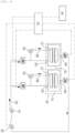
- FIG. 4 is a view illustrating an electrode manufacturing apparatus having two drying lines according to another embodiment of the present specification.
- Humidifying parts 26' and 26" and sensors 24' and 24" are respectively provided in the individual drying lines, and the control part 50, which collects information from the individual drying lines, individually controls the humidity of the high-temperature vapor in the individual drying lines.
Landscapes
- Engineering & Computer Science (AREA)
- Mechanical Engineering (AREA)
- General Engineering & Computer Science (AREA)
- Manufacturing & Machinery (AREA)
- Chemical & Material Sciences (AREA)
- Chemical Kinetics & Catalysis (AREA)
- Electrochemistry (AREA)
- General Chemical & Material Sciences (AREA)
- Textile Engineering (AREA)
- Battery Electrode And Active Subsutance (AREA)
- Coating Apparatus (AREA)
Claims (4)
- Elektrodenherstellungsvorrichtung (100), umfassend:ein Zuführungsteil (10), das dazu konfiguriert ist, einen Elektrodenvorläufer (1) zuzuführen; wobei der Elektrodenvorläufer (1) eine Elektrodenaufschlämmung enthält, die auf einem Substrat angeordnet ist;ein Trocknungsteil (20), das dazu konfiguriert ist, die Elektrodenaufschlämmung zu trocknen, um eine Elektrode (2) herzustellen, wobei das Trocknungsteil (20) Folgendes beinhaltet:ein Luftzufuhrteil (21), das so konfiguriert ist, dass es dem Elektrodenvorläufer (1) einen Hochtemperaturdampf zuführt,ein Lufteinführungsteil (22), das so konfiguriert ist, dass es den Hochtemperaturdampf in einen Strömungsweg (23) einführt, wobei der Strömungsweg (23) so konfiguriert ist, dass er das Lufteinführungsteil (22) mit dem Luftzufuhrteil (21) verbindet,einen Sensor (24), der so konfiguriert ist, dass er eine Feuchtigkeit des Hochtemperaturdampfes in dem Strömungsweg (23) misst,ein Luftauslassteil (25), das so konfiguriert ist, dass es geöffnet oder geschlossen werden kann, um einen Teil des Hochtemperaturdampfes, der von dem Lufteinführungsteil (22) zu dem Luftzufuhrteil (21) entlang des Strömungsweges (23) zirkuliert, abzugeben, undein Befeuchtungsteil (26), das so konfiguriert ist, dass es den Hochtemperaturdampf befeuchtet, der von dem Lufteinführungsteil (22) zu dem Luftzufuhrteil (21) entlang des Strömungsweges (23) zirkuliert;ein Auslassteil (30), das zum Entladen der Elektrode (2) konfiguriert ist;ein Überwachungsteil (40), das so konfiguriert ist, dass es die von dem Auslassteil (30) entladene Elektrode (2) überwacht; undein Steuerteil (50), das so konfiguriert ist, dass es von dem Überwachungsteil (40) erhaltene Überwachungsinformationen und von dem Sensor (24) gemessene Feuchtigkeitsinformationen sammelt; wobei das Steuerteil (50) so konfiguriert ist, dass es steuert, ob das Luftauslassteil (25) geöffnet oder geschlossen wird, und dass es einen Grad der Befeuchtung durch das Befeuchtungsteil (26) steuert,wobei das Steuerteil (50) so konfiguriert ist, dass es die Feuchtigkeit des Hochtemperaturdampfes erhöht, wenn das Überwachungsteil (40) den Riss in der Elektrode (2) detektiert, bis kein Riss mehr in der Elektrode (2) detektiert wird, undwobei das Überwachungsteil (40) so konfiguriert ist, dass es eine bestimmte Feuchtigkeit des Hochtemperaturdampfes in dem Trocknungsteil (20) aufrechterhält, wenn das Überwachungsteil (40) keinen Riss in der Elektrode (2) detektiert, wobei das Steuerteil (50) so konfiguriert ist, dass es die Feuchtigkeit bestimmt, wenn kein Riss in der Elektrode (2) detektiert wird.
- Elektrodenherstellungsvorrichtung (100) nach Anspruch 1, wobei das Überwachungsteil (40) ein Sichterfassungsteil mit einer Kamera (41) umfasst, die so konfiguriert ist, dass sie einen Riss in der Elektrode (2) detektiert.
- Verfahren zur Herstellung einer Elektrode, umfassend:Zuführen eines Elektrodenvorläufers (1), der durch Auftragen einer Elektrodenaufschlämmung auf ein Substrat hergestellt wird, in ein Trocknungsteil (20);Trocknen der Elektrodenaufschlämmung, um eine Elektrode (2) herzustellen, während ein Hochtemperaturdampf zugeführt wird, um eine Feuchtigkeit des Hochtemperaturdampfes in dem Trocknungsteil (20) einzustellen;Entladen der Elektrode (2) aus dem Trocknungsteil (20);Überwachen der Elektrode (2); undSammeln von Überwachungsinformationen, die durch das Überwachen der Elektrode (2) erhalten werden, und Sammeln von Feuchtigkeitsinformationen des Hochtemperaturdampfes in dem Trocknungsteil (20) und Steuern der Feuchtigkeit in dem Trocknungsteil (20);wobei die Steuerung der Feuchtigkeit in dem Trocknungsteil (20) umfasst:Erhöhen der Feuchtigkeit in dem Trocknungsteil (20), wenn sich ein Riss in der Elektrode (2) bildet, bis kein Riss in der Elektrode (2) durch das Überwachen der Elektrode (2) detektiert wird; undBestimmen einer Feuchtigkeit, bei der kein Riss in der Elektrode (2) detektiert wird, und Steuern der Feuchtigkeit in dem Trocknungsteil (20), um die Feuchtigkeit so zu halten, dass sie der Feuchtigkeit entspricht, bei der kein Riss in der Elektrode (2) detektiert wird.
- Elektrodenherstellungsverfahren nach Anspruch 3,
wobei das Überwachen der Elektrode (2) das Detektieren eines Risses in der Elektrode (2) unter Verwendung einer Kamera (41) umfasst, die so konfiguriert ist, dass sie ein Bild einer Oberfläche der Elektrode (2) aufnimmt, nachdem die Elektrode (2) aus dem Trocknungsteil (20) entladen wurde.
Applications Claiming Priority (2)
| Application Number | Priority Date | Filing Date | Title |
|---|---|---|---|
| KR20210159461 | 2021-11-18 | ||
| PCT/KR2022/018238 WO2023090912A1 (ko) | 2021-11-18 | 2022-11-17 | 전극 제조 장치 및 방법 |
Publications (3)
| Publication Number | Publication Date |
|---|---|
| EP4254532A1 EP4254532A1 (de) | 2023-10-04 |
| EP4254532A4 EP4254532A4 (de) | 2024-07-17 |
| EP4254532B1 true EP4254532B1 (de) | 2025-06-04 |
Family
ID=86397441
Family Applications (1)
| Application Number | Title | Priority Date | Filing Date |
|---|---|---|---|
| EP22896109.0A Active EP4254532B1 (de) | 2021-11-18 | 2022-11-17 | Vorrichtung und verfahren zur herstellung von elektroden |
Country Status (8)
| Country | Link |
|---|---|
| US (1) | US20240072236A1 (de) |
| EP (1) | EP4254532B1 (de) |
| JP (1) | JP7592356B2 (de) |
| KR (1) | KR20230073131A (de) |
| CN (1) | CN116829890A (de) |
| ES (1) | ES3035635T3 (de) |
| HU (1) | HUE072027T2 (de) |
| WO (1) | WO2023090912A1 (de) |
Families Citing this family (1)
| Publication number | Priority date | Publication date | Assignee | Title |
|---|---|---|---|---|
| KR102872058B1 (ko) * | 2020-12-03 | 2025-10-15 | 주식회사 엘지에너지솔루션 | 전극의 건조 시스템 및 전극의 건조 방법 |
Citations (1)
| Publication number | Priority date | Publication date | Assignee | Title |
|---|---|---|---|---|
| JP2002273308A (ja) * | 2001-03-15 | 2002-09-24 | Matsushita Electric Ind Co Ltd | 乾燥状態測定装置およびそれを備えた塗膜乾燥機 |
Family Cites Families (16)
| Publication number | Priority date | Publication date | Assignee | Title |
|---|---|---|---|---|
| JPH0720570B2 (ja) * | 1988-06-30 | 1995-03-08 | 三菱製紙株式会社 | ドライヤー内ウエブ乾燥制御装置 |
| JPH0441765A (ja) * | 1990-06-05 | 1992-02-12 | Iwasaki Tsuneo | 染上がり見本布の乾燥装置 |
| JP5534771B2 (ja) | 2009-10-09 | 2014-07-02 | パナソニック株式会社 | 塗布膜の乾燥方法と乾燥装置 |
| DE102010026604A1 (de) * | 2010-07-09 | 2012-01-12 | Heidelberger Druckmaschinen Ag | Bogenverarbeitende Maschine mit einem oder mehreren Trocknern |
| JP5897808B2 (ja) * | 2011-03-29 | 2016-03-30 | 東レエンジニアリング株式会社 | 電極板の製造装置 |
| JP5392332B2 (ja) * | 2011-09-15 | 2014-01-22 | 第一実業株式会社 | 乾燥装置 |
| WO2013111647A1 (ja) | 2012-01-23 | 2013-08-01 | 日本碍子株式会社 | 乾燥炉ユニット及び乾燥炉 |
| CN104344707B (zh) * | 2013-07-31 | 2018-04-10 | 株式会社大气社 | 干燥炉设备 |
| KR102257673B1 (ko) * | 2014-05-15 | 2021-05-28 | 삼성에스디아이 주식회사 | 전극판 건조 장치 및 전극판 건조 방법 |
| KR101747493B1 (ko) * | 2014-07-17 | 2017-06-14 | 주식회사 엘지화학 | 전극 및 이를 제조하는 전극 코팅 장치 |
| KR20170109912A (ko) * | 2016-03-22 | 2017-10-10 | 삼성에스디아이 주식회사 | 극판 건조 장치 |
| KR102245127B1 (ko) * | 2018-01-08 | 2021-04-28 | 주식회사 엘지화학 | 전극기재의 건조 상태를 모니터링하는 방법 및 장치 |
| JP2020027828A (ja) | 2018-08-09 | 2020-02-20 | 株式会社村田製作所 | 電子部品の製造装置 |
| KR102752344B1 (ko) * | 2019-08-01 | 2025-01-10 | 주식회사 엘지에너지솔루션 | 수분공급부가 구비된 전극 건조 장치 및 이를 이용한 전극 건조 방법 |
| KR20210050721A (ko) * | 2019-10-29 | 2021-05-10 | 현대자동차주식회사 | 이차전지용 전극의 건조 시스템 |
| CN212856488U (zh) * | 2020-05-11 | 2021-04-02 | 湖北亿纬动力有限公司 | 一种新风预处理系统 |
-
2022
- 2022-11-17 JP JP2023540192A patent/JP7592356B2/ja active Active
- 2022-11-17 HU HUE22896109A patent/HUE072027T2/hu unknown
- 2022-11-17 WO PCT/KR2022/018238 patent/WO2023090912A1/ko not_active Ceased
- 2022-11-17 KR KR1020220154779A patent/KR20230073131A/ko active Pending
- 2022-11-17 US US18/270,048 patent/US20240072236A1/en active Pending
- 2022-11-17 EP EP22896109.0A patent/EP4254532B1/de active Active
- 2022-11-17 CN CN202280008943.1A patent/CN116829890A/zh active Pending
- 2022-11-17 ES ES22896109T patent/ES3035635T3/es active Active
Patent Citations (1)
| Publication number | Priority date | Publication date | Assignee | Title |
|---|---|---|---|---|
| JP2002273308A (ja) * | 2001-03-15 | 2002-09-24 | Matsushita Electric Ind Co Ltd | 乾燥状態測定装置およびそれを備えた塗膜乾燥機 |
Also Published As
| Publication number | Publication date |
|---|---|
| JP7592356B2 (ja) | 2024-12-02 |
| JP2024503339A (ja) | 2024-01-25 |
| US20240072236A1 (en) | 2024-02-29 |
| HUE072027T2 (hu) | 2025-10-28 |
| ES3035635T3 (en) | 2025-09-05 |
| CN116829890A (zh) | 2023-09-29 |
| WO2023090912A1 (ko) | 2023-05-25 |
| EP4254532A1 (de) | 2023-10-04 |
| KR20230073131A (ko) | 2023-05-25 |
| EP4254532A4 (de) | 2024-07-17 |
Similar Documents
| Publication | Publication Date | Title |
|---|---|---|
| KR101467640B1 (ko) | 전극 건조 방법 및 전극 건조 장치 | |
| KR101550487B1 (ko) | 전극 건조 방법 및 전극 건조 장치 | |
| US20150086866A1 (en) | Flow controller of drying oven with automatic air charge for manufacturing secondary battery | |
| KR101286003B1 (ko) | 이차 전지의 전극 슬러리 건조 방법 및 장치 | |
| KR20190084470A (ko) | 전극기재의 건조 상태를 모니터링하는 방법 및 장치 | |
| EP4106041B1 (de) | Elektrodentrocknungssystem und elektrodentrocknungsverfahren | |
| CN103779537B (zh) | 电池电极的制造方法和装置 | |
| EP4254532B1 (de) | Vorrichtung und verfahren zur herstellung von elektroden | |
| JP2015011964A (ja) | 電池用電極板,電池用電極板の製造装置及び電池用電極板の製造方法 | |
| US20230175776A1 (en) | Automatic Electrode Drying Control System and Automatic Electrode Drying Control Method | |
| EP4212808B1 (de) | Elektrodentrocknungssystem | |
| EP4106040B1 (de) | Elektrodentrocknungssystem und elektrodentrocknungsverfahren | |
| KR102872057B1 (ko) | 가습부를 포함하는 전극 건조 장치 | |
| JP2001176502A (ja) | 電池用電極の製造方法 | |
| JP7754954B2 (ja) | バッテリー部品の乾燥方法およびシステム | |
| WO2001037356A1 (en) | Apparatus and method for extracting plasticizer | |
| KR101201124B1 (ko) | 이차 전지의 전극 활물질 도포 방법 | |
| JP2003178752A (ja) | シート状電極の乾燥評価方法 | |
| EP4328533B1 (de) | Elektrodenblatt-ofentrocknungsvorrichtung, batterieherstellungsvorrichtung und elektrodenblatt-ofentrocknungsverfahren | |
| CN219664310U (zh) | 一种极片烘箱及电池生产设备 | |
| KR100659863B1 (ko) | 이차 전지의 전극 형성 방법 | |
| JP7794533B2 (ja) | 電極乾燥システムおよびそれを用いた電極乾燥方法 | |
| CN117553527A (zh) | 烘干装置及极片成型设备 | |
| JP4975909B2 (ja) | リチウムイオン二次電池用負極の製造方法 | |
| US20250377160A1 (en) | Drying system for semi-dry ptfe-based electrode manufacturing |
Legal Events
| Date | Code | Title | Description |
|---|---|---|---|
| STAA | Information on the status of an ep patent application or granted ep patent |
Free format text: STATUS: THE INTERNATIONAL PUBLICATION HAS BEEN MADE |
|
| PUAI | Public reference made under article 153(3) epc to a published international application that has entered the european phase |
Free format text: ORIGINAL CODE: 0009012 |
|
| STAA | Information on the status of an ep patent application or granted ep patent |
Free format text: STATUS: REQUEST FOR EXAMINATION WAS MADE |
|
| 17P | Request for examination filed |
Effective date: 20230630 |
|
| AK | Designated contracting states |
Kind code of ref document: A1 Designated state(s): AL AT BE BG CH CY CZ DE DK EE ES FI FR GB GR HR HU IE IS IT LI LT LU LV MC ME MK MT NL NO PL PT RO RS SE SI SK SM TR |
|
| A4 | Supplementary search report drawn up and despatched |
Effective date: 20240617 |
|
| RIC1 | Information provided on ipc code assigned before grant |
Ipc: B05D 3/04 20060101ALI20240611BHEP Ipc: F26B 25/06 20060101ALI20240611BHEP Ipc: F26B 21/08 20060101ALI20240611BHEP Ipc: F26B 21/00 20060101ALI20240611BHEP Ipc: H01M 4/04 20060101AFI20240611BHEP |
|
| GRAP | Despatch of communication of intention to grant a patent |
Free format text: ORIGINAL CODE: EPIDOSNIGR1 |
|
| STAA | Information on the status of an ep patent application or granted ep patent |
Free format text: STATUS: GRANT OF PATENT IS INTENDED |
|
| DAV | Request for validation of the european patent (deleted) | ||
| DAX | Request for extension of the european patent (deleted) | ||
| INTG | Intention to grant announced |
Effective date: 20250226 |
|
| GRAS | Grant fee paid |
Free format text: ORIGINAL CODE: EPIDOSNIGR3 |
|
| P01 | Opt-out of the competence of the unified patent court (upc) registered |
Free format text: CASE NUMBER: APP_13992/2025 Effective date: 20250321 |
|
| GRAA | (expected) grant |
Free format text: ORIGINAL CODE: 0009210 |
|
| STAA | Information on the status of an ep patent application or granted ep patent |
Free format text: STATUS: THE PATENT HAS BEEN GRANTED |
|
| AK | Designated contracting states |
Kind code of ref document: B1 Designated state(s): AL AT BE BG CH CY CZ DE DK EE ES FI FR GB GR HR HU IE IS IT LI LT LU LV MC ME MK MT NL NO PL PT RO RS SE SI SK SM TR |
|
| REG | Reference to a national code |
Ref country code: GB Ref legal event code: FG4D |
|
| REG | Reference to a national code |
Ref country code: CH Ref legal event code: EP |
|
| REG | Reference to a national code |
Ref country code: DE Ref legal event code: R096 Ref document number: 602022015671 Country of ref document: DE |
|
| REG | Reference to a national code |
Ref country code: IE Ref legal event code: FG4D |
|
| REG | Reference to a national code |
Ref country code: ES Ref legal event code: FG2A Ref document number: 3035635 Country of ref document: ES Kind code of ref document: T3 Effective date: 20250905 |
|
| REG | Reference to a national code |
Ref country code: NL Ref legal event code: MP Effective date: 20250604 |
|
| PG25 | Lapsed in a contracting state [announced via postgrant information from national office to epo] |
Ref country code: FI Free format text: LAPSE BECAUSE OF FAILURE TO SUBMIT A TRANSLATION OF THE DESCRIPTION OR TO PAY THE FEE WITHIN THE PRESCRIBED TIME-LIMIT Effective date: 20250604 |
|
| REG | Reference to a national code |
Ref country code: LT Ref legal event code: MG9D |
|
| PG25 | Lapsed in a contracting state [announced via postgrant information from national office to epo] |
Ref country code: GR Free format text: LAPSE BECAUSE OF FAILURE TO SUBMIT A TRANSLATION OF THE DESCRIPTION OR TO PAY THE FEE WITHIN THE PRESCRIBED TIME-LIMIT Effective date: 20250905 Ref country code: NO Free format text: LAPSE BECAUSE OF FAILURE TO SUBMIT A TRANSLATION OF THE DESCRIPTION OR TO PAY THE FEE WITHIN THE PRESCRIBED TIME-LIMIT Effective date: 20250904 |
|
| PG25 | Lapsed in a contracting state [announced via postgrant information from national office to epo] |
Ref country code: PL Free format text: LAPSE BECAUSE OF FAILURE TO SUBMIT A TRANSLATION OF THE DESCRIPTION OR TO PAY THE FEE WITHIN THE PRESCRIBED TIME-LIMIT Effective date: 20250604 |
|
| PG25 | Lapsed in a contracting state [announced via postgrant information from national office to epo] |
Ref country code: BG Free format text: LAPSE BECAUSE OF FAILURE TO SUBMIT A TRANSLATION OF THE DESCRIPTION OR TO PAY THE FEE WITHIN THE PRESCRIBED TIME-LIMIT Effective date: 20250604 |
|
| PG25 | Lapsed in a contracting state [announced via postgrant information from national office to epo] |
Ref country code: HR Free format text: LAPSE BECAUSE OF FAILURE TO SUBMIT A TRANSLATION OF THE DESCRIPTION OR TO PAY THE FEE WITHIN THE PRESCRIBED TIME-LIMIT Effective date: 20250604 |
|
| PG25 | Lapsed in a contracting state [announced via postgrant information from national office to epo] |
Ref country code: RS Free format text: LAPSE BECAUSE OF FAILURE TO SUBMIT A TRANSLATION OF THE DESCRIPTION OR TO PAY THE FEE WITHIN THE PRESCRIBED TIME-LIMIT Effective date: 20250904 |
|
| REG | Reference to a national code |
Ref country code: HU Ref legal event code: AG4A Ref document number: E072027 Country of ref document: HU |
|
| PG25 | Lapsed in a contracting state [announced via postgrant information from national office to epo] |
Ref country code: LV Free format text: LAPSE BECAUSE OF FAILURE TO SUBMIT A TRANSLATION OF THE DESCRIPTION OR TO PAY THE FEE WITHIN THE PRESCRIBED TIME-LIMIT Effective date: 20250604 |
|
| PG25 | Lapsed in a contracting state [announced via postgrant information from national office to epo] |
Ref country code: NL Free format text: LAPSE BECAUSE OF FAILURE TO SUBMIT A TRANSLATION OF THE DESCRIPTION OR TO PAY THE FEE WITHIN THE PRESCRIBED TIME-LIMIT Effective date: 20250604 |
|
| PG25 | Lapsed in a contracting state [announced via postgrant information from national office to epo] |
Ref country code: PT Free format text: LAPSE BECAUSE OF FAILURE TO SUBMIT A TRANSLATION OF THE DESCRIPTION OR TO PAY THE FEE WITHIN THE PRESCRIBED TIME-LIMIT Effective date: 20251006 |
|
| PGFP | Annual fee paid to national office [announced via postgrant information from national office to epo] |
Ref country code: HU Payment date: 20251127 Year of fee payment: 4 |
|
| REG | Reference to a national code |
Ref country code: AT Ref legal event code: MK05 Ref document number: 1801254 Country of ref document: AT Kind code of ref document: T Effective date: 20250604 |
|
| PG25 | Lapsed in a contracting state [announced via postgrant information from national office to epo] |
Ref country code: IS Free format text: LAPSE BECAUSE OF FAILURE TO SUBMIT A TRANSLATION OF THE DESCRIPTION OR TO PAY THE FEE WITHIN THE PRESCRIBED TIME-LIMIT Effective date: 20251004 |
|
| PGFP | Annual fee paid to national office [announced via postgrant information from national office to epo] |
Ref country code: DE Payment date: 20251020 Year of fee payment: 4 |
|
| PG25 | Lapsed in a contracting state [announced via postgrant information from national office to epo] |
Ref country code: SM Free format text: LAPSE BECAUSE OF FAILURE TO SUBMIT A TRANSLATION OF THE DESCRIPTION OR TO PAY THE FEE WITHIN THE PRESCRIBED TIME-LIMIT Effective date: 20250604 Ref country code: AT Free format text: LAPSE BECAUSE OF FAILURE TO SUBMIT A TRANSLATION OF THE DESCRIPTION OR TO PAY THE FEE WITHIN THE PRESCRIBED TIME-LIMIT Effective date: 20250604 |
|
| PGFP | Annual fee paid to national office [announced via postgrant information from national office to epo] |
Ref country code: FR Payment date: 20251021 Year of fee payment: 4 |
|
| PGFP | Annual fee paid to national office [announced via postgrant information from national office to epo] |
Ref country code: BE Payment date: 20251020 Year of fee payment: 4 |
|
| PG25 | Lapsed in a contracting state [announced via postgrant information from national office to epo] |
Ref country code: CZ Free format text: LAPSE BECAUSE OF FAILURE TO SUBMIT A TRANSLATION OF THE DESCRIPTION OR TO PAY THE FEE WITHIN THE PRESCRIBED TIME-LIMIT Effective date: 20250604 |
|
| PG25 | Lapsed in a contracting state [announced via postgrant information from national office to epo] |
Ref country code: EE Free format text: LAPSE BECAUSE OF FAILURE TO SUBMIT A TRANSLATION OF THE DESCRIPTION OR TO PAY THE FEE WITHIN THE PRESCRIBED TIME-LIMIT Effective date: 20250604 |
|
| PG25 | Lapsed in a contracting state [announced via postgrant information from national office to epo] |
Ref country code: SK Free format text: LAPSE BECAUSE OF FAILURE TO SUBMIT A TRANSLATION OF THE DESCRIPTION OR TO PAY THE FEE WITHIN THE PRESCRIBED TIME-LIMIT Effective date: 20250604 |
|
| PG25 | Lapsed in a contracting state [announced via postgrant information from national office to epo] |
Ref country code: IT Free format text: LAPSE BECAUSE OF FAILURE TO SUBMIT A TRANSLATION OF THE DESCRIPTION OR TO PAY THE FEE WITHIN THE PRESCRIBED TIME-LIMIT Effective date: 20250604 |
|
| PGFP | Annual fee paid to national office [announced via postgrant information from national office to epo] |
Ref country code: ES Payment date: 20251215 Year of fee payment: 4 |
|
| PG25 | Lapsed in a contracting state [announced via postgrant information from national office to epo] |
Ref country code: RO Free format text: LAPSE BECAUSE OF FAILURE TO SUBMIT A TRANSLATION OF THE DESCRIPTION OR TO PAY THE FEE WITHIN THE PRESCRIBED TIME-LIMIT Effective date: 20250604 |