EP4251371B1 - Exzentergetriebe für eine werkzeugmaschine - Google Patents
Exzentergetriebe für eine werkzeugmaschine Download PDFInfo
- Publication number
- EP4251371B1 EP4251371B1 EP21810008.9A EP21810008A EP4251371B1 EP 4251371 B1 EP4251371 B1 EP 4251371B1 EP 21810008 A EP21810008 A EP 21810008A EP 4251371 B1 EP4251371 B1 EP 4251371B1
- Authority
- EP
- European Patent Office
- Prior art keywords
- eccentric
- machine tool
- drive
- gear
- eccentric gear
- Prior art date
- Legal status (The legal status is an assumption and is not a legal conclusion. Google has not performed a legal analysis and makes no representation as to the accuracy of the status listed.)
- Active
Links
Images


Classifications
-
- B—PERFORMING OPERATIONS; TRANSPORTING
- B25—HAND TOOLS; PORTABLE POWER-DRIVEN TOOLS; MANIPULATORS
- B25B—TOOLS OR BENCH DEVICES NOT OTHERWISE PROVIDED FOR, FOR FASTENING, CONNECTING, DISENGAGING OR HOLDING
- B25B27/00—Hand tools, specially adapted for fitting together or separating parts or objects whether or not involving some deformation, not otherwise provided for
- B25B27/02—Hand tools, specially adapted for fitting together or separating parts or objects whether or not involving some deformation, not otherwise provided for for connecting objects by press fit or detaching same
- B25B27/10—Hand tools, specially adapted for fitting together or separating parts or objects whether or not involving some deformation, not otherwise provided for for connecting objects by press fit or detaching same inserting fittings into hoses
-
- B—PERFORMING OPERATIONS; TRANSPORTING
- B21—MECHANICAL METAL-WORKING WITHOUT ESSENTIALLY REMOVING MATERIAL; PUNCHING METAL
- B21D—WORKING OR PROCESSING OF SHEET METAL OR METAL TUBES, RODS OR PROFILES WITHOUT ESSENTIALLY REMOVING MATERIAL; PUNCHING METAL
- B21D39/00—Application of procedures in order to connect objects or parts, e.g. coating with sheet metal otherwise than by plating; Tube expanders
- B21D39/04—Application of procedures in order to connect objects or parts, e.g. coating with sheet metal otherwise than by plating; Tube expanders of tubes with tubes; of tubes with rods
- B21D39/046—Connecting tubes to tube-like fittings
-
- B—PERFORMING OPERATIONS; TRANSPORTING
- B21—MECHANICAL METAL-WORKING WITHOUT ESSENTIALLY REMOVING MATERIAL; PUNCHING METAL
- B21D—WORKING OR PROCESSING OF SHEET METAL OR METAL TUBES, RODS OR PROFILES WITHOUT ESSENTIALLY REMOVING MATERIAL; PUNCHING METAL
- B21D39/00—Application of procedures in order to connect objects or parts, e.g. coating with sheet metal otherwise than by plating; Tube expanders
- B21D39/04—Application of procedures in order to connect objects or parts, e.g. coating with sheet metal otherwise than by plating; Tube expanders of tubes with tubes; of tubes with rods
- B21D39/048—Application of procedures in order to connect objects or parts, e.g. coating with sheet metal otherwise than by plating; Tube expanders of tubes with tubes; of tubes with rods using presses for radially crimping tubular elements
-
- B—PERFORMING OPERATIONS; TRANSPORTING
- B25—HAND TOOLS; PORTABLE POWER-DRIVEN TOOLS; MANIPULATORS
- B25B—TOOLS OR BENCH DEVICES NOT OTHERWISE PROVIDED FOR, FOR FASTENING, CONNECTING, DISENGAGING OR HOLDING
- B25B25/00—Implements for fastening, connecting or tensioning of wire or strip
- B25B25/005—Implements for fastening, connecting or tensioning of wire or strip for applying wire clasps to hose couplings
Definitions
- the invention relates to a machine tool, in particular a pipe press, comprising a drive, an output shaft, a threaded spindle drive and a linear actuator, wherein a torque generated by the drive can be transmitted to the linear actuator via the output shaft, the threaded spindle drive connected to the output shaft.
- the forming machines available on the market have a pressing head driven by a pressing cylinder.
- the pressing cylinder is often driven hydraulically to move the pressing head.
- An electric motor in turn drives a hydraulic pump, which drives the linear movement of the pressing cylinder.
- mechanical pressing/cutting and crimping tools are also available on the market, which generate the pressing pressure via a threaded spindle drive in combination with an electric motor instead of hydraulics.
- the rotational movement of the electric motor is transformed into a linear movement via a threaded spindle.
- These machine tools often contain a gear connected between the spindle and the electric motor to reduce the required motor torque and thus enable the motor to be dimensioned smaller.
- machine tools with hydraulically driven linear actuators known from the prior art tend to be too complex to develop and too large or too long, inefficient and too heavy to handle.
- machine tools with hydraulically driven linear actuators known from the prior art require a relatively long time for a single work cycle, where a work cycle can be, for example, a forming or cutting cycle.
- a machine tool according to the preamble of claim 1 is described in document US 9 808 851 B2 revealed.
- the present invention therefore has the object of providing a machine tool, in particular a pipe press, comprising a drive, an output shaft, a threaded spindle drive and a linear actuator in order to solve the above-mentioned problems.
- a machine tool in particular a pipe press, according to claim 1 comprising a drive, an output shaft, a threaded spindle drive and a linear actuator, wherein a torque generated by the drive can be transmitted to the linear actuator via the output shaft, the threaded spindle drive connected to the output shaft.
- the machine tool contains an eccentric gear device for torque adjustment between the drive and the threaded spindle drive, wherein the eccentric gear device contains a drive eccentric drivable by the drive, an eccentric gear drivable by the drive eccentric, a compensating coupling drivable by the eccentric gear for torque transmission from the eccentric gear to the output shaft.
- the compensating coupling can be designed as a torsionally rigid compensating coupling.
- an eccentric gear device By using an eccentric gear device, a hydraulically driven linear actuator can be omitted, which means that the machine tool can be less complex to design and smaller, more efficient and lighter to handle. Furthermore, by using an eccentric gear device, the time for a work cycle is significantly reduced. In addition, by using an eccentric gear device, relatively high gear ratios can be achieved in just a single gear stage. In addition, by using an eccentric gear device, very high gear ratios (i.e., for example, 1 to 1000) can be achieved in just a single gear stage.
- the eccentric gear device can also be referred to as a circular thrust gear device or cycloidal gear device.
- the eccentric gear device can also be referred to as a planetary gear device, which on the one hand is designed without a sun gear and on the other hand a planetary gear is driven directly via an eccentric.
- the eccentric gear device is essentially designed as a planetary gear, although a sun gear can be dispensed with.
- the eccentric gear of the eccentric gear device is driven directly via the drive eccentric.
- an involute toothing may be included between a hollow gear fixedly connected to a housing and the eccentric gear.
- involute gearing By using involute gearing, a more efficient rolling movement occurs at the respective contact point of the teeth of the hollow gear and eccentric gear instead of a sliding movement. Furthermore, the number of required rolling bearings on or at the hollow gear can be reduced to a minimum.
- the eccentric gear has an outer diameter that essentially corresponds to the inner diameter of the hollow gear.
- a maximum gear ratio between the eccentric gear and the hollow gear is achieved when the difference in the number of teeth between the eccentric gear and the hollow gear is a minimum.
- the minimum is a difference in the number of teeth of one.
- the compensating coupling may be designed as a parallel crank coupling.
- the parallel crank coupling can also be called a pin coupling or sliding block coupling.
- the eccentric gear device may be single-stage and to have a gear ratio of 1:10 to 1:100.
- the eccentric gear and the hollow gear may have a tooth number difference of 1 to 2 teeth.
- the hollow gear may have between 20 and 200 teeth.
- the hollow gear may have a maximum inner diameter between 20 and 200 mm.
- the hollow gear of the eccentric gear device may be rotatably mounted in the housing.
- the eccentric gear device may consist at least partially of a metallic sintered material.
- a sintered material By using a sintered material, the sliding ability of the components, i.e. in particular within the eccentric gear device, can be increased.
- the eccentric gear device may consist at least partially of a polymer.
- the eccentric gear device can be produced more cheaply and easily.
- the imbalance and friction can be reduced and the efficiency increased.
- a machine tool 1 according to the invention is shown in an exemplary embodiment as a pipe press.
- the machine tool 1 can also be designed as any other cutting or forming tool.
- the machine tool 1 according to the invention it is also possible for the machine tool 1 according to the invention to be designed as a squeezing device for chemical substances, such as adhesive or dowel compound. Such squeezing devices can also be referred to as dispensers.
- the machine tool 1 designed as a pipe press essentially has a housing 2, a tool holder 3 and a power supply 4.
- the housing 2 of the machine tool 1 is essentially cylindrical and contains a front end 2a, a rear end 2b, a left side surface 2c, a right side surface 2d, a top side 2e and a bottom side 2f.
- a middle part 2g of the housing 2 serves as a handle for holding or guiding the machine tool 1. In the Figures 1 to 3 only the left side surface 2c is shown.
- the energy supply 4 is positioned at the rear end 2b of the housing 2 of the machine tool 1.
- the energy supply 4 is designed as an accumulator (also called a battery).
- the energy supply 4 designed as an accumulator can be releasably connected to the rear end 2b of the housing 2 of the machine tool 1 via an interface 5.
- the accumulator 4 is used to supply the machine tool 1 or the electrical consumers of the machine tool 1 with electrical energy.
- the power supply 4 of the machine tool 1 can also be designed as a power cable for connecting the machine tool 1 to a power source (i.e. socket).
- the tool holder 3 is positioned at the front end 2a of the housing 2 of the machine tool 1 for releasably receiving and holding a tool 6.
- a tool 6 in the form of a forming tool is positioned on the tool holder 3.
- the forming tool 6 is designed as a so-called press head.
- the forming tool 6 designed as a press head is used essentially for processing and in particular for forming lines, ie pipes and tubes. The lines are not shown in the figures.
- An activation switch 7 is positioned on the underside 2f of the housing 2 of the machine tool 1.
- the machine tool 1 can be started and stopped using the activation switch 7.
- a drive 8, a drive shaft 9, an eccentric gear device 10, an output shaft 11, a threaded spindle drive 12 and a linear actuator 13 are essentially positioned inside the housing 2 of the machine tool 1.
- the drive 8 is designed as a brushless electric motor.
- the drive 8 designed as a brushless electric motor, is shown connected to the eccentric gear device 10 via the drive shaft 9. Through the connection to the drive shaft 9, a torque generated in the drive 8 is transmitted from the drive 8 to the eccentric gear device 10.
- the eccentric gear device 10 further essentially contains a drive eccentric 14, an eccentric gear 15, a hollow gear 16 and a compensating coupling 17.
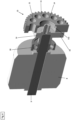
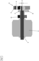
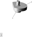
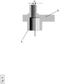
- the drive eccentric 14 has a compensating mass 18 (also called balancing mass or balancing mass), which is connected to the drive 8 via the drive shaft 9, cf. Figure 8 to 10 .
- a bearing 30 is positioned between the drive eccentric 14 and the drive 8, see Figure 6 and 7 .
- the eccentric gear 15 contains a recess 15a for a ball bearing 19.
- the drive eccentric 14 is fitted into the ball bearing 19 and is thereby connected in a rotationally fixed manner to the eccentric gear 15. By rotating the drive eccentric 14 in the direction of rotation R, the eccentric gear 15 is also rotated in a wobbling manner.
- the eccentric gear 15 is positioned in the hollow gear 16.
- the hollow gear 16 is connected in a rotationally fixed manner to the inside of the housing 2 of the machine tool 1.
- the eccentric gear 15 and the hollow gear 16 have an involute toothing 20, see. Figure 5 .
- the hollow gear 16 has an inner diameter DH of 100 mm. According to an alternative embodiment, the inner diameter DH of the hollow gear 16 can be between 20 and 200 mm.
- the eccentric gear 15 contains a number of recesses 21 arranged in a circle around the drive eccentric 14.
- the recesses 21 are shown in the form of eleven through holes. However, there can also be more or fewer than eleven through holes. According to an alternative embodiment, the recesses 21 can also be shown as blind holes.
- the compensating coupling 17 is designed as a parallel crank coupling with coupling elements 22.
- Each of the through-bores 21 of the eccentric gear 15 serves to accommodate a coupling element 22.
- the coupling elements 22 are designed as coupling pins.
- the diameter DA of a recess 21 designed as a through-bore is twice as large as the diameter DK of a coupling element 22 designed as a coupling pin.
- the drive 8 designed as an electric motor, can rotate at a speed value between 10,000 and 30,000 rpm at a maximum extension and retraction speed of the linear actuator 13. In particular, a speed value between 15,000 and 18,000 rpm is provided for the drive 8.
Landscapes
- Engineering & Computer Science (AREA)
- Mechanical Engineering (AREA)
- Transmission Devices (AREA)
- Retarders (AREA)
Description
- Die Erfindung betrifft eine Werkzeugmaschine, insbesondere eine Rohrpresse, enthaltend einen Antrieb, eine Abtriebswelle, einen Gewindespindeltrieb und einen Linearaktuator, wobei ein von dem Antrieb erzeugtes Drehmoment über die Abtriebswelle, den mit der Abtriebswelle verbundenen Gewindespindeltrieb auf den Linearaktuator übertragbar ist.
- Aus dem Stand der Technik sind unterschiedliche Werkzeugmaschinen für Umform- und Schneideprozesse bekannt. Mit Hilfe dieser speziellen Werkzeugmaschinen können beispielsweise Armierungseisen durchtrennt, Rohre mechanisch verbunden oder Schlauchschellen aufgepresst werden. Zu den Aufgaben des mechanischen Verbindens gehört auch das sogenannte Crimpen, Bördeln und Quetschen.
- Um die erforderlichen hohen Presskräfte für beispielsweise das Crimpen von Stahlrohren zu realisieren, verfügen die am Markt erhältlichen Umformmaschinen einen von einem Presszylinder angetriebenen Presskopf. Häufig wird dabei der Presszylinder zum Bewegen des Presskopfs hydraulisch angetrieben. Ein Elektromotor treibt wiederum eine Hydraulikpumpe an, welche die Linearbewegung des Presszylinders abtreibt. Alternativ sind auch mechanische Press/Schneide und Crimptools am Markt erhältlich, welche statt der Hydraulik den Pressdruck über einen Gewindespindeltrieb in Kombination mit einem Elektromotor erzeugen. Hierbei wird die Rotationsbewegung des Elektromotors über eine Gewindespindel in eine lineare Bewegung transformiert. Häufig enthalten diese Werkzeugmaschine ein zwischen Spindel und Elektromotor geschaltetes Getriebe zur Reduktion des erforderlichen Motordrehmoments und um dadurch den Motor kleiner dimensionieren zu können.
- Die aus dem Stand der Technik bekannten Werkzeugmaschinen mit hydraulisch angetriebenen Linearaktuator neigen jedoch in der Entwicklung zu komplex sowie in der Handhabung zu groß bzw. zu lang, ineffizient und zu schwer zu sein. Des Weiteren benötigen die aus dem Stand der Technik bekannten Werkzeugmaschinen mit hydraulisch angetriebenen Linearaktuator relativ lang für einen einzigen Arbeitszyklus, wobei ein Arbeitszyklus beispielsweise ein Umform- bzw. Schneidezyklus sein kann. Eine Werkzeugmaschine nach dem Oberbegriff des Anspruchs 1 ist in Dokument
US 9 808 851 B2 - Die vorliegende Erfindung stellt sich daher die Aufgabe eine Werkzeugmaschine, insbesondere eine Rohrpresse, enthaltend einen Antrieb, eine Abtriebswelle, einen Gewindespindeltrieb und einen Linearaktuator bereitzustellen, um die vorstehend genannten Probleme zu lösen.
- Die Aufgabe wird insbesondere gelöst durch das Bereitstellen einer Werkzeugmaschine, insbesondere eine Rohrpresse, gemäß Anspruch 1 enthaltend einen Antrieb, eine Abtriebswelle, einen Gewindespindeltrieb und einen Linearaktuator, wobei ein von dem Antrieb erzeugtes Drehmoment über die Abtriebswelle, den mit der Abtriebswelle verbundenen Gewindespindeltrieb auf den Linearaktuator übertragbar ist.
- Erfindungsgemäß enthält die Werkzeugmaschine eine Exzentergetriebevorrichtung für eine Drehmomentanpassung zwischen dem Antrieb und dem Gewindespindeltrieb, wobei die Exzentergetriebevorrichtung ein von dem Antrieb antreibbaren Antriebsexzenter, ein von dem Antriebexzenter antreibbares Exzenterzahnrad, eine von dem Exzenterzahnrad antreibbare Ausgleichskupplung zur Drehmomentübertragung von dem Exzenterzahnrad auf die Abtriebswelle enthält.
- Die Ausgleichskupplung kann dabei als drehstarre Ausgleichskupplung ausgestaltete sein.
- Durch die Verwendung einer Exzentergetriebevorrichtung kann auf einen hydraulisch angetriebenen Linearaktuator verzichtet werden, wodurch die Werkzeugmaschine in der Entwicklung weniger komplex sowie in der Handhabung kleiner, effizienter und leichter sein kann. Ferner wird durch die Verwendung einer Exzentergetriebevorrichtung die Dauer für einen Arbeitszyklus deutlich reduziert. Darüber hinaus können durch die Verwendung einer Exzentergetriebevorrichtung relativ hohe Übersetzungsverhältnisse in nur einer einzigen Übersetzungsstufe erreicht werden. Darüber hinaus können durch die Verwendung einer Exzentergetriebevorrichtung sehr hoher Übersetzungsverhältnisse (d.h. beispielsweise 1 zu 1000) in lediglich einer einzigen Getriebestufe verwirklicht werden.
- Die Exzentergetriebevorrichtung kann auch als Kreisschubgetriebevorrichtung oder Zykloidgetriebevorrichtung bezeichnet werden. Darüber hinaus kann die Exzentergetriebevorrichtung auch als Planetengetriebevorrichtung bezeichnet werden, welche zum einen ohne ein Sonnenzahnrad ausgestaltet ist und zum anderen ein Planetenzahnrad direkt über einen Exzenter angetrieben wird.
- Die Exzentergetriebevorrichtung ist im Wesentlichen als Planetengetriebe ausgestaltet, wobei jedoch auf ein Sonnenzahnrad verzichtet werden kann. Das Exzenterzahnrad der Exzentergetriebevorrichtung wird direkt über den Antriebsexzenter angetrieben.
- Gemäß einer vorteilhaften Ausführungsform der vorliegenden Erfindung kann es möglich sein, dass zwischen einem fest mit einem Gehäuse verbundenen Hohlzahnrad und dem Exzenterzahnrad eine Evolventenverzahnung enthalten ist.
- Durch die Verwendung einer Evolventenverzahnung erfolgt im jeweiligen Kontaktpunkt der Zähne des Hohlzahnrades und Exzenterzahnrades anstelle einer Gleitbewegung eine effizientere Wälzbewegung. Weiterhin kann hiermit auch Anzahl der notwendigen Wälzlager auf bzw. an dem Hohlzahnrad auf ein Minimum reduziert werden.
- Das Exzenterzahnrad weist einen Außendurchmesser auf, der im Wesentlichen einem Innendurchmesser des Hohlzahnrads entspricht. Eine maximale Übersetzung zwischen dem Exzenterzahnrad und dem Hohlzahnrad ist gegeben, wenn die Zahnzahldifferenz zwischen Exzenterzahnrad und dem Hohlzahnrad ein Minium beträgt. Das Minimum hierbei ist ein Zahnzahldifferenz von eins.
- Entsprechend einer weiteren vorteilhaften Ausführungsform der vorliegenden Erfindung kann es möglich sein, dass die Ausgleichskupplung als Parallelkurbelkupplung ausgestaltet ist.
- Die Parallelkurbelkupplung kann auch als Stiftkupplung oder Gleitsteinkupplung bezeichnet werden.
- Durch die Verwendung einer Parallelkurbelkupplung wird die im Verhältnis zur Drehgeschwindigkeit des Exzenterzahnrads relativ langsame Drehgeschwindigkeit der Abtriebswelle nicht eingeschränkt.
- Gemäß einer weiteren vorteilhaften Ausführungsform der vorliegenden Erfindung kann es möglich sein, dass die Exzentergetriebevorrichtung einstufig und mit einer Übersetzungsverhältnis von 1:10 bis 1:100 ausgeführt ist.
- Entsprechend einer weiteren vorteilhaften Ausführungsform der vorliegenden Erfindung kann es möglich sein, dass das Exzenterzahnrad und das Hohlzahnrad eine Zahnzahldifferenz von 1 bis 2 Zähne aufweist.
- Gemäß einer weiteren vorteilhaften Ausführungsform der vorliegenden Erfindung kann es möglich sein, dass das Hohlzahnrad zwischen 20 und 200 Zähnen aufweist.
- Entsprechend einer weiteren vorteilhaften Ausführungsform der vorliegenden Erfindung kann es möglich sein, dass das Hohlzahnrad einen maximalen Innendurchmesser zwischen 20 und 200 mm aufweist.
- Gemäß einer weiteren vorteilhaften Ausführungsform der vorliegenden Erfindung kann es möglich sein, dass das Hohlzahnrad der Exzentergetriebevorrichtung drehbar im Gehäuse gelagert ist.
- Entsprechend einer weiteren vorteilhaften Ausführungsform der vorliegenden Erfindung kann es möglich sein, dass die Exzentergetriebevorrichtung wenigstens teilweise aus einem metallischen Sinterwerkstoff besteht. Durch die Verwendung eines Sinterwerkstoffs kann die Gleitfähigkeit der Bauteile, d.h. insbesondere innerhalb der Exzentergetriebevorrichtung gesteigert werden.
- Gemäß einer weiteren vorteilhaften Ausführungsform der vorliegenden Erfindung kann es möglich sein, dass die Exzentergetriebevorrichtung wenigstens teilweise aus einem Polymer besteht. Durch die Verwendung eines Polymers kann die Exzentergetriebevorrichtung günstiger und leichter produziert werden. Darüber hinaus können die Unwucht und Reibung reduziert sowie der Wirkungsgrad erhöht werden.
- Weitere Vorteile ergeben sich aus der folgenden Figurenbeschreibung.
- In den Figuren sind verschiedene Ausführungsbeispiele der vorliegenden Erfindung dargestellt.
- Die Figuren, die Beschreibung und die Patentansprüche enthalten zahlreiche Merkmale in Kombination. Der Fachmann wird die Merkmale zweckmässigerweise auch einzeln betrachten und zu sinnvollen weiteren Kombinationen zusammenfassen.
- In den Figuren sind gleiche und gleichartige Komponente und Baugruppen mit gleichen Bezugszeichen beziffert.
- Es zeigt:
- Figur 1
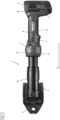
- eine seitliche Ansicht auf eine Werkzeugmaschine in Ausgestaltung einer Rohrpresse;
- Figur 2
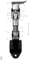
- eine seitliche Schnittansicht auf die beispielhaft als Rohrpresse ausgestaltete Werkzeugmaschine mit einem Antrieb, einer Abtriebswelle, einem Gewindespindeltrieb, einem Linearaktuator und einer Exzentergetriebevorrichtung;
- Figur 3
- eine perspektivische Schnittansicht auf die beispielhaft als Rohrpresse ausgestaltete Werkzeugmaschine mit dem Antrieb, der Abtriebswelle, dem Gewindespindeltrieb, dem Linearaktuator und der Exzentergetriebevorrichtung;
- Figur 4
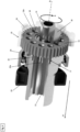
- eine perspektivische Schnittansicht auf die Exzentergetriebevorrichtung mit einem Teil der Abtriebswelle sowie einem ersten und zweiten Lager;
- Figur 5
- eine Frontansicht auf die Exzentergetriebevorrichtung mit einem Antriebsexzenter, einem Exzenterzahnrad sowie einem Hohlzahnrad;
- Figur 6
- eine perspektivische Schnittansicht auf den Antrieb, die Abtriebswelle, das erste Lager, den Antriebsexzenter und ein Exzenterzahnrad;
- Figur 7
- eine seitliche Schnittansicht auf den Antrieb, die Abtriebswelle, das erste Lager, den Antriebsexzenter und das Exzenterzahnrad;
- Figur 8
- eine perspektivische Ansicht auf den Antriebsexzenter mit einer Ausgleichsmasse;
- Figur 9
- eine Seitenansicht auf den Antriebsexzenter mit der Ausgleichsmasse; und
- Figur 10
- eine seitliche Schnittansicht durch den Antriebsexzenter.
- In
Figur 1 bis 3 ist eine erfindungsgemäße Werkzeugmaschine 1 in einer beispielhaften Ausgestaltung als Rohrpresse gezeigt. Anstelle der Ausgestaltung als Rohrpresse kann die Werkzeugmaschine 1 auch als jede andere Schneid- oder Umformwerkzeug ausgestaltet sein. So ist es insbesondere auch möglich, dass die erfindungsgemäße Werkzeugmaschine 1 als Auspressgerät für chemische Substanzen, wie z.B. Klebstoff oder Dübelmasse ausgestaltet ist. Derartige Auspressgeräte könne auch als Dispenser bezeichnet werden. - Wie in
Figur 1 zu erkennen ist, weist die als Rohrpresse ausgestaltete Werkzeugmaschine 1 im Wesentlichen ein Gehäuse 2, eine Werkzeugaufnahme 3 und eine Energieversorgung 4 auf. - Das Gehäuse 2 der Werkzeugmaschine 1 ist im Wesentlichen zylindrisch ausgestaltet und enthält ein vorderes Ende 2a, ein hinteres Ende 2b, eine linke Seitenfläche 2c, eine rechte Seitenfläche 2d, eine Oberseite 2e und eine Unterseite 2f. Ein mittlerer Anteil 2g des Gehäuses 2 dient als Handgriff zum Halten bzw. Führen der Werkzeugmaschine 1. In den
Figuren 1 bis 3 ist lediglich die linke Seitenfläche 2c dargestellt. - An dem hinteren Ende 2b des Gehäuses 2 der Werkzeugmaschine 1 ist die Energieversorgung 4 positioniert. Im vorliegenden Ausführungsbeispiel ist die Energieversorgung 4 als Akkumulator (auch Akku oder Batterie genannt) ausgestaltet. Die als Akkumulator ausgestaltete Energieversorgung 4 kann wiederlösbar über eine Schnittstelle 5 mit dem hinteren Ende 2b des Gehäuses 2 der Werkzeugmaschine 1 verbunden werden. Mit Hilfe des Akkumulators 4 wird die Werkzeugmaschine 1 bzw. die elektrischen Verbraucher der Werkzeugmaschine 1 mit elektrischer Energie versorgt.
- Gemäß einer alternativen Ausgestaltung der vorliegenden Erfindung kann die Energieversorgung 4 der Werkzeugmaschine 1 auch als Stromkabel ausgestaltet sein zum Verbinden der Werkzeugmaschine 1 mit einer Stromnetzquelle (d.h. Steckdose).
- An dem vorderen Ende 2a des Gehäuses 2 der Werkzeugmaschine 1 ist die Werkzeugaufnahme 3 positioniert zum wiederlösbaren Aufnehmen und Halten eines Werkzeugs 6. An der Werkzeugaufnahme 3 ist in dem vorliegenden Ausführungsbeispiel ein Werkzeug 6 in Form eines Umformwerkzeugs positioniert. Das Umformwerkzeug 6 ist im vorliegenden Ausführungsbeispiel als sogenannter Presskopf ausgestaltet. Das als Presskopf ausgestaltete Umformwerkzeug 6 dient im Wesentlichen zum Bearbeiten und insbesondere Umformen von Leitungen, d.h. Rohre und Röhren. Die Leitungen sind in den Figuren nicht gezeigt.
- An der Unterseite 2f des Gehäuses 2 der Werkzeugmaschine 1 ist ein Aktivierungsschalter 7 positioniert. Mit Hilfe des Aktivierungsschalters 7 kann die Werkzeugmaschine 1 gestartet und gestoppt werden.
- Im Inneren des Gehäuses 2 der Werkzeugmaschine 1 ist im Wesentlichen ein Antrieb 8, eine Antriebswelle 9, eine Exzentergetriebevorrichtung 10, eine Abtriebswelle 11, ein Gewindespindeltrieb 12 und ein Linearaktuator 13 positioniert. Der Antrieb 8 ist in dem vorliegenden Ausführungsbeispiel als bürstenloser Elektromotor ausgestaltet.
- Wie in
Figur 2 ,3 ,6 und7 dargestellt ist der als bürstenloser Elektromotor ausgestaltete Antrieb 8 über die Antriebswelle 9 mit der Exzentergetriebevorrichtung 10 verbunden. Durch die Verbindung mit der Antriebswelle 9 wird ein in dem Antrieb 8 erzeugtes Drehmoment von dem Antrieb 8 auf die Exzentergetriebevorrichtung 10 übertragen. - Mit Hilfe der Exzentergetriebevorrichtung 10 kann eine Drehzahlübersetzung vom Antrieb 8 auf die Abtriebswelle 11 erzeugt werden.
- Wie insbesondere in
Figur 4 gezeigt, enthält die Exzentergetriebevorrichtung 10 weiterhin im Wesentlichen einen Antriebsexzenter 14, ein Exzenterzahnrad 15, ein Hohlzahnrad 16 sowie eine Ausgleichskupplung 17. Der Antriebsexzenter 14 weist eine Ausgleichsmasse 18 (auch Wuchtmasse oder Auswuchtmasse genannt) auf, der über die Antriebswelle 9 mit dem Antrieb 8 verbunden ist, vgl.Figur 8 bis 10 . Zwischen dem Antriebsexzenter 14 und dem Antrieb 8 ist ein Lager 30 positioniert, vgl.Figur 6 und7 . Das Exzenterzahnrad 15 enthält eine Aussparung 15a für ein Kugellager 19. Der Antriebsexzenter 14 ist in das Kugellager 19 eingepasst und dadurch mit dem Exzenterzahnrad 15 drehfest verbunden. Durch ein Drehen des Antriebsexzenters 14 in Drehrichtung R wird auch das Exzenterzahnrad 15 entsprechend taumelnd gedreht. - Darüber hinaus ist das Exzenterzahnrad 15 in dem Hohlzahnrad 16 positioniert. Das Hohlzahnrad 16 ist drehfest mit der Innenseite des Gehäuses 2 der Werkzeugmaschine 1 verbunden. Das Exzenterzahnrad 15 und das Hohlzahnrad 16 weisen eine Evolventenverzahnung 20 auf, vgl.
Figur 5 . Das Hohlzahnrad 16 weist einen Innendurchmesser DH von 100 mm auf. Gemäß einer alternativen Ausführungsform kann der Innendurchmesser DH des Hohlzahnrads 16 zwischen 20 und 200 mm betragen. - Des Weiteren enthält das Exzenterzahnrad 15 eine Anzahl an kreisförmig um den Antriebsexzenter 14 angeordnete Aussparungen 21. In dem Ausführungsbeispiel, welches in den Figuren gezeigt ist, sind die Aussparungen 21 in Form von elf Durchbohrungen dargestellt. Es können jedoch auch mehr oder weniger als elf Durchbohrungen sein. Gemäß einer alternativen Ausgestaltung können die Aussparungen 21 auch als Sacklöcher dargestellt sein.
- Im vorliegenden Ausführungsbeispiel ist die Ausgleichskupplung 17 als Parallelkurbelkupplung mit Kupplungselementen 22 ausgestaltet. Jede der Durchbohrungen 21 des Exzenterzahnrads 15 dient jeweils zum Aufnehmen eines Kupplungselements 22. Im vorliegenden Ausführungsbeispiel sind die Kupplungselements 22 als Kupplungsstifte ausgestaltet.
- Der Durchmesser DA einer als Durchbohrung ausgestalteten Aussparung 21 ist dabei doppelt so groß wie der Durchmesser DK eines als Kupplungsstift ausgestalteten Kupplungselements 22.
- Der Durchmesser einer Aussparung 21 entspricht dabei wenigstens dem Durchmesser eines Kupplungselements 22 und einem zweifachen Wert der Exzentrizität E des Exzenterzahnrads 15.

- DAussparung: Durchmesser der Aussparung
- DKupplungselement: Durchmesser des Kupplungselements
- E: Exzentrizität des Exzenterzahnrads.
- Die Ausgleichskupplung 17 kann daher als Parallelkurbelkupplung oder auch als Stift- bzw. Kurbelkupplung bezeichnet werden.
- Wie in
Figur 4 ersichtlich ragt das freie Ende 22a eines jeden Kupplungsstiftes 22 in Pfeilrichtung A aus den Durchbohrungen 21 des Exzenterzahnrads 15 heraus. Die freien Enden 22a eines jeden Kupplungsstiftes 22 sind wiederum mit der Abtriebswelle 11 so verbunden, dass ein Drehmoment von den Kupplungsstiften 22 der Ausgleichskupplung 17 auf die Abtriebswelle 11 übertragen werden kann. - Die Abtriebswelle 11 weist im Wesentlichen eine zylindrische Form auf. Mit Hilfe eines Hauptlagers 23 und Sekundärlagers 24 ist die Abtriebswelle 11 im Inneren des Gehäuses 2 der Werkzeugmaschine 1 gelagert. Das Hauptlager 23 ist als Wälzlager bzw. Kugellager und das Sekundärlager 24 ist als Gleitlager ausgestaltet. Gemäß eines alternativen Ausführungsbeispiels kann sowohl das Hauptlager 23 als auch das Sekundärlager 24 entweder als Wälzlager oder Gleitlager ausgestaltet sein. Entsprechend einer alternativen Ausgestaltungsform kann auch lediglich nur ein einziges Lager vorgesehen sein.
- Wie bereits vorstehend beschrieben ist die Abtriebswelle 11 mit der Ausgleichskupplung 17 der Exzentergetriebevorrichtung 10 verbunden. Die Abtriebswelle 11 grenzt an den Gewindespindeltrieb 12 an. Der Gewindespindeltrieb 12 ist dabei mit der Abtriebswelle 11 verbunden. Durch den Gewindespindeltrieb 12 kann die Drehbewegung der Abtriebswelle 11 in eine Linearbewegung umgewandelt werden.
- Wie insbesondere den
Figuren 2 und3 entnommen werden kann ist der Gewindespindeltrieb 12 mit dem Linearaktuator 13 verbunden. - Der Linearaktuator 13 enthält im Wesentlichen eine Druckfeder 25 sowie eine Schubstange 26. Die Druckfeder 25 agiert dabei als Rückstellfeder für den Linearaktuator 13.
- An dem Linearaktuator 13 ist eine Kraftflussumlenkungseinrichtung 27 vorgesehen. Mit Hilfe des Linearaktuators 13 und der Kraftflussumlenkungseinrichtung 27 wird die lineare Kraft des Linearaktuators 13 so auf die Werkzeugaufnahme 3 übertragen, dass das als Presskopf ausgestaltete Werkzeug 6 zwischen einer geöffneten und geschlossenen Position bewegt werden kann.
- Der als Elektromotor ausgestaltete Antrieb 8 kann bei einer maximalen Ausfahr- und Einfahrgeschwindigkeit des Linearaktuators 13 mit einem Drehzahlwert zwischen 10.000 und 30.000 rpm dreht. Insbesondere ist ein Drehzahlwert zwischen 15.000 bis 18.000 rpm für den Antrieb 8 vorgesehen.
-
- 1
- Werkzeugmaschine
- 2
- Gehäuse
- 2a
- vorderes Ende 2a des Gehäuses
- 2b
- hinteres Ende des Gehäuses
- 2c
- linke Seitenfläche des Gehäuses
- 2d
- rechte Seitenfläche des Gehäuses
- 2e
- Oberseite des Gehäuses
- 2f
- Unterseite des Gehäuses
- 3
- Werkzeugaufnahme
- 4
- Energieversorgung
- 5
- Schnittstelle
- 6
- Werkzeug
- 7
- Aktivierungsschalter
- 8
- Antrieb
- 9
- Antriebswelle
- 10
- Exzentergetriebevorrichtung
- 11
- Abtriebswelle
- 12
- Gewindespindeltrieb
- 13
- Linearaktuator
- 14
- Antriebsexzenter
- 15
- Exzenterzahnrad
- 15a
- Aussparung am Exzenterzahnrad
- 16
- Hohlzahnrad
- 17
- Ausgleichskupplung
- 18
- Ausgleichsmasse
- 19
- Kugellager
- 20
- Evolventenverzahnung
- 21
- Aussparungen am Exzenterzahnrad
- 22
- Kupplungselement
- 22a
- freies Ende am Kupplungselement
- 23
- Hauptlager
- 24
- Sekundärlager
- 25
- Druckfeder
- 26
- Schubstange
- 27
- Kraftflussumlenkungseinrichtung
- 30
- Lager
- DA
- Durchmesser einer Aussparung
- DK
- Durchmesser eines Kupplungselements
- DH
- Innendurchmesser des Hohlzahnrads
- E
- Exzentrizität des Exzenterzahnrads
Claims (11)
- Werkzeugmaschine (1), insbesondere eine Rohrpresse, enthaltend einen Antrieb (8), eine Abtriebswelle (11), einen Gewindespindeltrieb (12) und einen Linearaktuator (13), wobei ein von dem Antrieb (8) erzeugtes Drehmoment über die Abtriebswelle (11), den mit der Abtriebswelle (11) verbundenen Gewindespindeltrieb (12) auf den Linearaktuator (13) übertragbar ist,
dadurch gekennzeichnet, dass eine Exzentergetriebevorrichtung (10) für eine Drehmomentanpassung zwischen dem Antrieb (8) und dem Gewindespindeltrieb (12) enthalten ist, wobei die Exzentergetriebevorrichtung (10) ein von dem Antrieb (8) antreibbaren Antriebsexzenter (14), ein von dem Antriebexzenter (14) antreibbares Exzenterzahnrad (15), eine von dem Exzenterzahnrad (15) antreibbare Ausgleichskupplung (17) zur Drehmomentübertragung von dem Exzenterzahnrad (15) auf die Abtriebswelle (11) enthält. - Werkzeugmaschine (1) nach Anspruch 1,
dadurch gekennzeichnet, dass zwischen einem fest mit einem Gehäuse (2) verbundenen Hohlzahnrad (16) und dem Exzenterzahnrad (15) eine Evolventenverzahnung (20) enthalten ist. - Werkzeugmaschine (1) nach Anspruch 1 oder 2,
dadurch gekennzeichnet, dass die Ausgleichskupplung (17) als Parallelkurbelkupplung ausgestaltet ist. - Werkzeugmaschine (1) nach wenigstens einem der Ansprüche 1 bis 3,
dadurch gekennzeichnet, dass die Exzentergetriebevorrichtung (10) einstufig und mit einer Übersetzungsverhältnis von 1:10 bis 1:100 ausgeführt ist. - Werkzeugmaschine (1) nach wenigstens einem der Ansprüche 2 bis 4,
dadurch gekennzeichnet, dass das Exzenterzahnrad (15) und das Hohlzahnrad (16) eine Zahnzahldifferenz von 1 bis 2 Zähne aufweist. - Werkzeugmaschine (1) nach wenigstens einem der Ansprüche 2 bis 5,
dadurch gekennzeichnet, dass das Hohlzahnrad (16) zwischen 20 und 200 Zähnen aufweist. - Werkzeugmaschine (1) nach wenigstens einem der Ansprüche 2 bis 6,
dadurch gekennzeichnet, dass das Hohlzahnrad (16) einen maximalen Innendurchmesser zwischen 20 und 200 mm aufweist. - Werkzeugmaschine (1) nach wenigstens einem der Ansprüche 2 bis 7,
dadurch gekennzeichnet, dass das Hohlzahnrad (16) der Exzentergetriebevorrichtung (10) drehbar im Gehäuse (2) gelagert ist. - Werkzeugmaschine (1) nach wenigstens einem der Ansprüche 2 bis 8,
dadurch gekennzeichnet, dass die Exzentergetriebevorrichtung (10) wenigstens teilweise aus einem metallischen Sinterwerkstoff besteht. - Werkzeugmaschine (1) nach wenigstens einem der Ansprüche 2 bis 9,
dadurch gekennzeichnet, dass die Exzentergetriebevorrichtung (10) wenigstens teilweise aus einem Polymer besteht. - Werkzeugmaschine (1) nach wenigstens einem der Ansprüche 1 bis 10,
dadurch gekennzeichnet, dass das Exzenterzahnrad (15) wenigstens eine Aussparungen (21) zur Aufnahme eines Kupplungselements (22) enthält, wobei der Durchmesser (DA) einer Aussparung (21) wenigstens dem Durchmesser (DK) eines Kupplungselements (22) und einem zweifachen Wert der Exzentrizität (E) des Exzenterzahnrads (15) entspricht.
Applications Claiming Priority (2)
| Application Number | Priority Date | Filing Date | Title |
|---|---|---|---|
| EP20210196.0A EP4005733A1 (de) | 2020-11-27 | 2020-11-27 | Exzentergetriebe für eine werkzeugmaschine |
| PCT/EP2021/081220 WO2022111998A1 (de) | 2020-11-27 | 2021-11-10 | Exzentergetriebe für eine werkzeugmaschine |
Publications (2)
| Publication Number | Publication Date |
|---|---|
| EP4251371A1 EP4251371A1 (de) | 2023-10-04 |
| EP4251371B1 true EP4251371B1 (de) | 2024-09-04 |
Family
ID=73642594
Family Applications (4)
| Application Number | Title | Priority Date | Filing Date |
|---|---|---|---|
| EP20210196.0A Withdrawn EP4005733A1 (de) | 2020-11-27 | 2020-11-27 | Exzentergetriebe für eine werkzeugmaschine |
| EP21156580.9A Active EP4005735B1 (de) | 2020-11-27 | 2021-02-11 | Werkzeugmaschine mit gewindespindeltrieb |
| EP21778362.0A Pending EP4251370A1 (de) | 2020-11-27 | 2021-09-13 | Werkzeugmaschine mit gewindespindeltrieb |
| EP21810008.9A Active EP4251371B1 (de) | 2020-11-27 | 2021-11-10 | Exzentergetriebe für eine werkzeugmaschine |
Family Applications Before (3)
| Application Number | Title | Priority Date | Filing Date |
|---|---|---|---|
| EP20210196.0A Withdrawn EP4005733A1 (de) | 2020-11-27 | 2020-11-27 | Exzentergetriebe für eine werkzeugmaschine |
| EP21156580.9A Active EP4005735B1 (de) | 2020-11-27 | 2021-02-11 | Werkzeugmaschine mit gewindespindeltrieb |
| EP21778362.0A Pending EP4251370A1 (de) | 2020-11-27 | 2021-09-13 | Werkzeugmaschine mit gewindespindeltrieb |
Country Status (4)
| Country | Link |
|---|---|
| US (2) | US12257676B2 (de) |
| EP (4) | EP4005733A1 (de) |
| CN (2) | CN116507434A (de) |
| WO (2) | WO2022111875A1 (de) |
Families Citing this family (5)
| Publication number | Priority date | Publication date | Assignee | Title |
|---|---|---|---|---|
| EP4005733A1 (de) | 2020-11-27 | 2022-06-01 | Hilti Aktiengesellschaft | Exzentergetriebe für eine werkzeugmaschine |
| EP4006382A1 (de) | 2020-11-30 | 2022-06-01 | Hilti Aktiengesellschaft | Federelement an kopplungsvorrichtung |
| USD1042068S1 (en) * | 2021-05-19 | 2024-09-17 | Gustav Klauke Gmbh | Hydraulic press tool |
| DE102022212148A1 (de) * | 2022-11-15 | 2024-05-16 | Mahle International Gmbh | Crimp-Werkzeug und damit hergestellter Wärmeübertrager |
| EP4530021A1 (de) * | 2023-09-28 | 2025-04-02 | Hilti Aktiengesellschaft | Mobile werkzeugmaschine mit einem einen anschlag aufweisenden gewindespindeltrieb |
Family Cites Families (32)
| Publication number | Priority date | Publication date | Assignee | Title |
|---|---|---|---|---|
| US4799844A (en) * | 1988-01-11 | 1989-01-24 | Trw Inc | Elliptical thread design |
| US5195354A (en) * | 1989-03-31 | 1993-03-23 | Japan Storage Battery Co., Ltd. | Cam crank mechanism and motor driven hydraulic tool |
| US5511439A (en) | 1994-07-22 | 1996-04-30 | Las Navas Garcia; Jose M. | Pushing mechansim |
| NL1011731C2 (nl) | 1999-04-06 | 2000-10-09 | Skf Engineering & Res Services | Actuator met compacte tandwielreductie. |
| DE50014538D1 (de) * | 1999-05-28 | 2007-09-20 | Foell Remswerk | Vorrichtung zum Aufbringen einer Presskraft |
| DE10064901A1 (de) * | 2000-03-27 | 2001-10-04 | Continental Teves Ag & Co Ohg | Betätigungseinheit mit einem Gewindetrieb, einem Planetengetriebe und einem von diesen beeinflußten Betätigungselement |
| US7163192B2 (en) * | 2002-06-20 | 2007-01-16 | Kitz Corporation | Actuator for valve |
| US20050103170A1 (en) | 2003-11-18 | 2005-05-19 | Norberto Del Rio | Hydroligripcut pliers |
| DE102006023535B4 (de) | 2006-05-19 | 2008-12-18 | Keiper Gmbh & Co.Kg | Getriebestufe für einen Stellantrieb |
| DE102009040460B4 (de) * | 2009-09-01 | 2023-01-12 | Adient Us Llc | Antriebseinheit für einen Fahrzeugsitz, System und Fahrzeugsitz |
| DE202009015515U1 (de) * | 2009-11-17 | 2011-04-07 | Novopress Gmbh Pressen Und Presswerkzeuge & Co. Kommanditgesellschaft | Handgeführtes Pressgerät |
| DE202011101675U1 (de) * | 2011-06-10 | 2012-09-13 | Novopress Gmbh Pressen Und Presswerkzeuge & Co. Kg | Elektrohydraulisches Pressgerät |
| FR3009905B1 (fr) * | 2013-08-20 | 2015-09-04 | Virax Sa | Dispositif de detection de butee arriere sur un actionneur lineaire |
| FR3009902B1 (fr) * | 2013-08-20 | 2015-09-04 | Virax Sa | Dispositif de detection de presence d'un outil amovible d'un actionneur lineaire |
| FR3010254B1 (fr) | 2013-08-27 | 2017-02-10 | Virax Sa | Actionneur lineaire a architecture en ligne |
| US9808851B2 (en) * | 2015-04-02 | 2017-11-07 | Milwaukee Electric Tool Corporation | PEX crimping tool |
| ITUA20161807A1 (it) * | 2016-03-18 | 2017-09-18 | Cembre Spa | Utensile oleodinamico di compressione o taglio |
| US10675805B2 (en) * | 2016-12-14 | 2020-06-09 | Ridge Tool Company | Electrically powered crimp tool and method of using |
| US10512964B2 (en) * | 2016-12-14 | 2019-12-24 | Ridge Tool Company | Electrically powered crimp tool |
| DE102018209819A1 (de) | 2018-06-18 | 2019-12-19 | Zf Friedrichshafen Ag | Spindelantrieb für eine steer-by-wire-Lenkung sowie steer-by-wire-Lenkung |
| DE102018115788A1 (de) * | 2018-06-29 | 2020-01-02 | Schaeffler Technologies AG & Co. KG | Gewindetrieb und Linearaktuator mit diesem Gewindetrieb |
| DE102018121971A1 (de) | 2018-09-10 | 2020-03-12 | Gustav Klauke Gmbh | Presswerkzeug |
| DE102018124646A1 (de) * | 2018-10-05 | 2020-04-09 | Rothenberger Ag | Handwerkzeug zum umformenden und/oder trennenden Bearbeiten von Kunststoff- oder Metallwerkstücken, insbesondere Kunststoff- oder Metallrohren |
| WO2020069696A1 (de) * | 2018-10-05 | 2020-04-09 | Rothenberger Ag | Handwerkzeug zum umformenden und/oder trennenden bearbeiten von kunststoff- oder metallwerkstücken, insbesondere kunststoff- oder metallrohren |
| EP3639941A1 (de) * | 2018-10-19 | 2020-04-22 | Von Arx AG | Pressmaschine mit sensorsystem zur werkstück-identifikation |
| RU2018139004A (ru) * | 2018-11-06 | 2020-05-12 | Акционерное общество "Диаконт" | Линейный электромеханический привод c возможностью смазывания без демонтажа |
| EP3653341A1 (de) | 2018-11-13 | 2020-05-20 | Hilti Aktiengesellschaft | Handwerkzeugmaschine |
| KR102130846B1 (ko) * | 2019-04-26 | 2020-07-03 | 주식회사평화발레오 | 회전 출력형 액추에이터 |
| US11236849B2 (en) * | 2019-09-04 | 2022-02-01 | Techtronic Cordless Gp | Pressing tool and method for a re-pressing operation |
| EP4005733A1 (de) | 2020-11-27 | 2022-06-01 | Hilti Aktiengesellschaft | Exzentergetriebe für eine werkzeugmaschine |
| EP4005734A1 (de) | 2020-11-30 | 2022-06-01 | Hilti Aktiengesellschaft | Kopplungsmechanismus |
| EP4006382A1 (de) | 2020-11-30 | 2022-06-01 | Hilti Aktiengesellschaft | Federelement an kopplungsvorrichtung |
-
2020
- 2020-11-27 EP EP20210196.0A patent/EP4005733A1/de not_active Withdrawn
-
2021
- 2021-02-11 EP EP21156580.9A patent/EP4005735B1/de active Active
- 2021-09-13 CN CN202180073617.4A patent/CN116507434A/zh active Pending
- 2021-09-13 EP EP21778362.0A patent/EP4251370A1/de active Pending
- 2021-09-13 WO PCT/EP2021/075036 patent/WO2022111875A1/de not_active Ceased
- 2021-09-13 US US18/035,413 patent/US12257676B2/en active Active
- 2021-11-10 CN CN202180079187.7A patent/CN116490299A/zh active Pending
- 2021-11-10 EP EP21810008.9A patent/EP4251371B1/de active Active
- 2021-11-10 US US18/037,255 patent/US12479073B2/en active Active
- 2021-11-10 WO PCT/EP2021/081220 patent/WO2022111998A1/de not_active Ceased
Also Published As
| Publication number | Publication date |
|---|---|
| US12479073B2 (en) | 2025-11-25 |
| US20230415218A1 (en) | 2023-12-28 |
| EP4251370A1 (de) | 2023-10-04 |
| CN116507434A (zh) | 2023-07-28 |
| EP4251371A1 (de) | 2023-10-04 |
| US12257676B2 (en) | 2025-03-25 |
| WO2022111875A1 (de) | 2022-06-02 |
| CN116490299A (zh) | 2023-07-25 |
| US20230405779A1 (en) | 2023-12-21 |
| WO2022111998A1 (de) | 2022-06-02 |
| EP4005733A1 (de) | 2022-06-01 |
| EP4005735C0 (de) | 2024-04-10 |
| EP4005735A1 (de) | 2022-06-01 |
| EP4005735B1 (de) | 2024-04-10 |
Similar Documents
| Publication | Publication Date | Title |
|---|---|---|
| EP4251371B1 (de) | Exzentergetriebe für eine werkzeugmaschine | |
| EP4251903B1 (de) | Federelement an kopplungsvorrichtung | |
| EP4251373A1 (de) | Kopplungsmechanismus | |
| WO2002066866A1 (de) | Vorrichtung zum betätigen einer schaltwelle eines schaltegetriebes | |
| DE10051434A1 (de) | Baureihe von Adaptervorrichtungen und Adaptervorrichtung | |
| DE102012212404A1 (de) | Handwerkzeugmaschinenvorrichtung | |
| EP3065945B1 (de) | Getriebeeinheit und anordnung für eine stanzpresse | |
| EP3368799A1 (de) | Schaltvorrichtung und antriebseinheit für ein kraftfahrzeug | |
| DE4323114A1 (de) | Schalteinrichtung für ein Wendegetriebe mit selbsttätiger Übersetzungsänderung bei Richtungsänderung der treibenden Welle | |
| WO1992019835A1 (de) | Hydraulisch angetriebener bohrmotor zum tiefbohren | |
| EP4148298A1 (de) | Getriebevorrichtung für eine werkzeugmaschine | |
| EP2186606B1 (de) | Vorsatzvorrichtung für eine Rohrpressmaschine | |
| DE19620654A1 (de) | Verstellbare Axialkolbenmaschine in Schrägscheibenbauweise | |
| EP4101592B1 (de) | Pressvorrichtung und presssystem | |
| EP2086725A2 (de) | Elektrowerkzeugmaschine | |
| EP3943226A1 (de) | Bohrmaschine | |
| EP4400229B1 (de) | Handhaltbare zug- und druckvorrichtung | |
| EP4063606B1 (de) | Getriebe mit freilauf | |
| EP2837450A1 (de) | Spanneinrichtung | |
| DE202012102009U1 (de) | Antriebsvorrichtung für eine Elektro-Schweißzange sowie Schweißzange mit einer solchen Antriebsvorrichtung | |
| DE202009002009U1 (de) | Arbeitsspindeleinheit für Werkzeugmaschinen | |
| DE3508186A1 (de) | Vorrichtung zum erzeugen einer bewegung | |
| EP4385665A1 (de) | Pressvorrichtung | |
| EP4385664A1 (de) | Elektrohandwerkzeug und verfahren zum betreiben eines elektrohandwerkzeugs | |
| EP4438232A1 (de) | Bohrhammermaschine mit mehrfachantrieb |
Legal Events
| Date | Code | Title | Description |
|---|---|---|---|
| STAA | Information on the status of an ep patent application or granted ep patent |
Free format text: STATUS: UNKNOWN |
|
| STAA | Information on the status of an ep patent application or granted ep patent |
Free format text: STATUS: THE INTERNATIONAL PUBLICATION HAS BEEN MADE |
|
| PUAI | Public reference made under article 153(3) epc to a published international application that has entered the european phase |
Free format text: ORIGINAL CODE: 0009012 |
|
| STAA | Information on the status of an ep patent application or granted ep patent |
Free format text: STATUS: REQUEST FOR EXAMINATION WAS MADE |
|
| 17P | Request for examination filed |
Effective date: 20230627 |
|
| AK | Designated contracting states |
Kind code of ref document: A1 Designated state(s): AL AT BE BG CH CY CZ DE DK EE ES FI FR GB GR HR HU IE IS IT LI LT LU LV MC MK MT NL NO PL PT RO RS SE SI SK SM TR |
|
| DAV | Request for validation of the european patent (deleted) | ||
| DAX | Request for extension of the european patent (deleted) | ||
| GRAP | Despatch of communication of intention to grant a patent |
Free format text: ORIGINAL CODE: EPIDOSNIGR1 |
|
| STAA | Information on the status of an ep patent application or granted ep patent |
Free format text: STATUS: GRANT OF PATENT IS INTENDED |
|
| INTG | Intention to grant announced |
Effective date: 20240620 |
|
| GRAS | Grant fee paid |
Free format text: ORIGINAL CODE: EPIDOSNIGR3 |
|
| GRAA | (expected) grant |
Free format text: ORIGINAL CODE: 0009210 |
|
| STAA | Information on the status of an ep patent application or granted ep patent |
Free format text: STATUS: THE PATENT HAS BEEN GRANTED |
|
| AK | Designated contracting states |
Kind code of ref document: B1 Designated state(s): AL AT BE BG CH CY CZ DE DK EE ES FI FR GB GR HR HU IE IS IT LI LT LU LV MC MK MT NL NO PL PT RO RS SE SI SK SM TR |
|
| REG | Reference to a national code |
Ref country code: GB Ref legal event code: FG4D Free format text: NOT ENGLISH |
|
| REG | Reference to a national code |
Ref country code: CH Ref legal event code: EP |
|
| REG | Reference to a national code |
Ref country code: IE Ref legal event code: FG4D Free format text: LANGUAGE OF EP DOCUMENT: GERMAN |
|
| REG | Reference to a national code |
Ref country code: DE Ref legal event code: R096 Ref document number: 502021005078 Country of ref document: DE |
|
| REG | Reference to a national code |
Ref country code: LT Ref legal event code: MG9D |
|
| REG | Reference to a national code |
Ref country code: NL Ref legal event code: MP Effective date: 20240904 |
|
| PGFP | Annual fee paid to national office [announced via postgrant information from national office to epo] |
Ref country code: DE Payment date: 20241121 Year of fee payment: 4 |
|
| PG25 | Lapsed in a contracting state [announced via postgrant information from national office to epo] |
Ref country code: NO Free format text: LAPSE BECAUSE OF FAILURE TO SUBMIT A TRANSLATION OF THE DESCRIPTION OR TO PAY THE FEE WITHIN THE PRESCRIBED TIME-LIMIT Effective date: 20241204 |
|
| PG25 | Lapsed in a contracting state [announced via postgrant information from national office to epo] |
Ref country code: PL Free format text: LAPSE BECAUSE OF FAILURE TO SUBMIT A TRANSLATION OF THE DESCRIPTION OR TO PAY THE FEE WITHIN THE PRESCRIBED TIME-LIMIT Effective date: 20240904 Ref country code: FI Free format text: LAPSE BECAUSE OF FAILURE TO SUBMIT A TRANSLATION OF THE DESCRIPTION OR TO PAY THE FEE WITHIN THE PRESCRIBED TIME-LIMIT Effective date: 20240904 Ref country code: GR Free format text: LAPSE BECAUSE OF FAILURE TO SUBMIT A TRANSLATION OF THE DESCRIPTION OR TO PAY THE FEE WITHIN THE PRESCRIBED TIME-LIMIT Effective date: 20241205 |
|
| PG25 | Lapsed in a contracting state [announced via postgrant information from national office to epo] |
Ref country code: BG Free format text: LAPSE BECAUSE OF FAILURE TO SUBMIT A TRANSLATION OF THE DESCRIPTION OR TO PAY THE FEE WITHIN THE PRESCRIBED TIME-LIMIT Effective date: 20240904 |
|
| PGFP | Annual fee paid to national office [announced via postgrant information from national office to epo] |
Ref country code: FR Payment date: 20241128 Year of fee payment: 4 |
|
| PG25 | Lapsed in a contracting state [announced via postgrant information from national office to epo] |
Ref country code: LV Free format text: LAPSE BECAUSE OF FAILURE TO SUBMIT A TRANSLATION OF THE DESCRIPTION OR TO PAY THE FEE WITHIN THE PRESCRIBED TIME-LIMIT Effective date: 20240904 |
|
| PG25 | Lapsed in a contracting state [announced via postgrant information from national office to epo] |
Ref country code: HR Free format text: LAPSE BECAUSE OF FAILURE TO SUBMIT A TRANSLATION OF THE DESCRIPTION OR TO PAY THE FEE WITHIN THE PRESCRIBED TIME-LIMIT Effective date: 20240904 |
|
| PG25 | Lapsed in a contracting state [announced via postgrant information from national office to epo] |
Ref country code: ES Free format text: LAPSE BECAUSE OF FAILURE TO SUBMIT A TRANSLATION OF THE DESCRIPTION OR TO PAY THE FEE WITHIN THE PRESCRIBED TIME-LIMIT Effective date: 20240904 Ref country code: RS Free format text: LAPSE BECAUSE OF FAILURE TO SUBMIT A TRANSLATION OF THE DESCRIPTION OR TO PAY THE FEE WITHIN THE PRESCRIBED TIME-LIMIT Effective date: 20241204 |
|
| PG25 | Lapsed in a contracting state [announced via postgrant information from national office to epo] |
Ref country code: RS Free format text: LAPSE BECAUSE OF FAILURE TO SUBMIT A TRANSLATION OF THE DESCRIPTION OR TO PAY THE FEE WITHIN THE PRESCRIBED TIME-LIMIT Effective date: 20241204 Ref country code: PL Free format text: LAPSE BECAUSE OF FAILURE TO SUBMIT A TRANSLATION OF THE DESCRIPTION OR TO PAY THE FEE WITHIN THE PRESCRIBED TIME-LIMIT Effective date: 20240904 Ref country code: NO Free format text: LAPSE BECAUSE OF FAILURE TO SUBMIT A TRANSLATION OF THE DESCRIPTION OR TO PAY THE FEE WITHIN THE PRESCRIBED TIME-LIMIT Effective date: 20241204 Ref country code: LV Free format text: LAPSE BECAUSE OF FAILURE TO SUBMIT A TRANSLATION OF THE DESCRIPTION OR TO PAY THE FEE WITHIN THE PRESCRIBED TIME-LIMIT Effective date: 20240904 Ref country code: HR Free format text: LAPSE BECAUSE OF FAILURE TO SUBMIT A TRANSLATION OF THE DESCRIPTION OR TO PAY THE FEE WITHIN THE PRESCRIBED TIME-LIMIT Effective date: 20240904 Ref country code: GR Free format text: LAPSE BECAUSE OF FAILURE TO SUBMIT A TRANSLATION OF THE DESCRIPTION OR TO PAY THE FEE WITHIN THE PRESCRIBED TIME-LIMIT Effective date: 20241205 Ref country code: FI Free format text: LAPSE BECAUSE OF FAILURE TO SUBMIT A TRANSLATION OF THE DESCRIPTION OR TO PAY THE FEE WITHIN THE PRESCRIBED TIME-LIMIT Effective date: 20240904 Ref country code: ES Free format text: LAPSE BECAUSE OF FAILURE TO SUBMIT A TRANSLATION OF THE DESCRIPTION OR TO PAY THE FEE WITHIN THE PRESCRIBED TIME-LIMIT Effective date: 20240904 Ref country code: BG Free format text: LAPSE BECAUSE OF FAILURE TO SUBMIT A TRANSLATION OF THE DESCRIPTION OR TO PAY THE FEE WITHIN THE PRESCRIBED TIME-LIMIT Effective date: 20240904 |
|
| PG25 | Lapsed in a contracting state [announced via postgrant information from national office to epo] |
Ref country code: NL Free format text: LAPSE BECAUSE OF FAILURE TO SUBMIT A TRANSLATION OF THE DESCRIPTION OR TO PAY THE FEE WITHIN THE PRESCRIBED TIME-LIMIT Effective date: 20240904 |
|
| PG25 | Lapsed in a contracting state [announced via postgrant information from national office to epo] |
Ref country code: PT Free format text: LAPSE BECAUSE OF FAILURE TO SUBMIT A TRANSLATION OF THE DESCRIPTION OR TO PAY THE FEE WITHIN THE PRESCRIBED TIME-LIMIT Effective date: 20250106 Ref country code: IS Free format text: LAPSE BECAUSE OF FAILURE TO SUBMIT A TRANSLATION OF THE DESCRIPTION OR TO PAY THE FEE WITHIN THE PRESCRIBED TIME-LIMIT Effective date: 20250104 |
|
| PG25 | Lapsed in a contracting state [announced via postgrant information from national office to epo] |
Ref country code: RO Free format text: LAPSE BECAUSE OF FAILURE TO SUBMIT A TRANSLATION OF THE DESCRIPTION OR TO PAY THE FEE WITHIN THE PRESCRIBED TIME-LIMIT Effective date: 20240904 Ref country code: SM Free format text: LAPSE BECAUSE OF FAILURE TO SUBMIT A TRANSLATION OF THE DESCRIPTION OR TO PAY THE FEE WITHIN THE PRESCRIBED TIME-LIMIT Effective date: 20240904 |
|
| PG25 | Lapsed in a contracting state [announced via postgrant information from national office to epo] |
Ref country code: EE Free format text: LAPSE BECAUSE OF FAILURE TO SUBMIT A TRANSLATION OF THE DESCRIPTION OR TO PAY THE FEE WITHIN THE PRESCRIBED TIME-LIMIT Effective date: 20240904 |
|
| PG25 | Lapsed in a contracting state [announced via postgrant information from national office to epo] |
Ref country code: CZ Free format text: LAPSE BECAUSE OF FAILURE TO SUBMIT A TRANSLATION OF THE DESCRIPTION OR TO PAY THE FEE WITHIN THE PRESCRIBED TIME-LIMIT Effective date: 20240904 |
|
| PG25 | Lapsed in a contracting state [announced via postgrant information from national office to epo] |
Ref country code: IT Free format text: LAPSE BECAUSE OF FAILURE TO SUBMIT A TRANSLATION OF THE DESCRIPTION OR TO PAY THE FEE WITHIN THE PRESCRIBED TIME-LIMIT Effective date: 20240904 Ref country code: SK Free format text: LAPSE BECAUSE OF FAILURE TO SUBMIT A TRANSLATION OF THE DESCRIPTION OR TO PAY THE FEE WITHIN THE PRESCRIBED TIME-LIMIT Effective date: 20240904 |
|
| REG | Reference to a national code |
Ref country code: DE Ref legal event code: R097 Ref document number: 502021005078 Country of ref document: DE |
|
| REG | Reference to a national code |
Ref country code: CH Ref legal event code: PL |
|
| PG25 | Lapsed in a contracting state [announced via postgrant information from national office to epo] |
Ref country code: MC Free format text: LAPSE BECAUSE OF FAILURE TO SUBMIT A TRANSLATION OF THE DESCRIPTION OR TO PAY THE FEE WITHIN THE PRESCRIBED TIME-LIMIT Effective date: 20240904 |
|
| PG25 | Lapsed in a contracting state [announced via postgrant information from national office to epo] |
Ref country code: DK Free format text: LAPSE BECAUSE OF FAILURE TO SUBMIT A TRANSLATION OF THE DESCRIPTION OR TO PAY THE FEE WITHIN THE PRESCRIBED TIME-LIMIT Effective date: 20240904 |
|
| PLBE | No opposition filed within time limit |
Free format text: ORIGINAL CODE: 0009261 |
|
| STAA | Information on the status of an ep patent application or granted ep patent |
Free format text: STATUS: NO OPPOSITION FILED WITHIN TIME LIMIT |
|
| PG25 | Lapsed in a contracting state [announced via postgrant information from national office to epo] |
Ref country code: LU Free format text: LAPSE BECAUSE OF NON-PAYMENT OF DUE FEES Effective date: 20241110 |
|
| REG | Reference to a national code |
Ref country code: CH Ref legal event code: PL |
|
| PG25 | Lapsed in a contracting state [announced via postgrant information from national office to epo] |
Ref country code: CH Free format text: LAPSE BECAUSE OF NON-PAYMENT OF DUE FEES Effective date: 20241130 |
|
| 26N | No opposition filed |
Effective date: 20250605 |
|
| REG | Reference to a national code |
Ref country code: BE Ref legal event code: MM Effective date: 20241130 |
|
| PG25 | Lapsed in a contracting state [announced via postgrant information from national office to epo] |
Ref country code: SE Free format text: LAPSE BECAUSE OF FAILURE TO SUBMIT A TRANSLATION OF THE DESCRIPTION OR TO PAY THE FEE WITHIN THE PRESCRIBED TIME-LIMIT Effective date: 20240904 |
|
| PG25 | Lapsed in a contracting state [announced via postgrant information from national office to epo] |
Ref country code: BE Free format text: LAPSE BECAUSE OF NON-PAYMENT OF DUE FEES Effective date: 20241130 |
|
| PG25 | Lapsed in a contracting state [announced via postgrant information from national office to epo] |
Ref country code: IE Free format text: LAPSE BECAUSE OF NON-PAYMENT OF DUE FEES Effective date: 20241110 |