EP4251344B1 - Herstellverfahren für giessformen, kerne oder speiser - Google Patents
Herstellverfahren für giessformen, kerne oder speiser Download PDFInfo
- Publication number
- EP4251344B1 EP4251344B1 EP21820240.6A EP21820240A EP4251344B1 EP 4251344 B1 EP4251344 B1 EP 4251344B1 EP 21820240 A EP21820240 A EP 21820240A EP 4251344 B1 EP4251344 B1 EP 4251344B1
- Authority
- EP
- European Patent Office
- Prior art keywords
- component
- curing
- molding compound
- self
- molding
- Prior art date
- Legal status (The legal status is an assumption and is not a legal conclusion. Google has not performed a legal analysis and makes no representation as to the accuracy of the status listed.)
- Active
Links
Images


Classifications
-
- B—PERFORMING OPERATIONS; TRANSPORTING
- B22—CASTING; POWDER METALLURGY
- B22C—FOUNDRY MOULDING
- B22C1/00—Compositions of refractory mould or core materials; Grain structures thereof; Chemical or physical features in the formation or manufacture of moulds
- B22C1/02—Compositions of refractory mould or core materials; Grain structures thereof; Chemical or physical features in the formation or manufacture of moulds characterised by additives for special purposes, e.g. indicators, breakdown additives
-
- B—PERFORMING OPERATIONS; TRANSPORTING
- B22—CASTING; POWDER METALLURGY
- B22C—FOUNDRY MOULDING
- B22C1/00—Compositions of refractory mould or core materials; Grain structures thereof; Chemical or physical features in the formation or manufacture of moulds
- B22C1/16—Compositions of refractory mould or core materials; Grain structures thereof; Chemical or physical features in the formation or manufacture of moulds characterised by the use of binding agents; Mixtures of binding agents
- B22C1/18—Compositions of refractory mould or core materials; Grain structures thereof; Chemical or physical features in the formation or manufacture of moulds characterised by the use of binding agents; Mixtures of binding agents of inorganic agents
- B22C1/186—Compositions of refractory mould or core materials; Grain structures thereof; Chemical or physical features in the formation or manufacture of moulds characterised by the use of binding agents; Mixtures of binding agents of inorganic agents contaming ammonium or metal silicates, silica sols
- B22C1/188—Alkali metal silicates
-
- B—PERFORMING OPERATIONS; TRANSPORTING
- B22—CASTING; POWDER METALLURGY
- B22C—FOUNDRY MOULDING
- B22C1/00—Compositions of refractory mould or core materials; Grain structures thereof; Chemical or physical features in the formation or manufacture of moulds
- B22C1/16—Compositions of refractory mould or core materials; Grain structures thereof; Chemical or physical features in the formation or manufacture of moulds characterised by the use of binding agents; Mixtures of binding agents
- B22C1/20—Compositions of refractory mould or core materials; Grain structures thereof; Chemical or physical features in the formation or manufacture of moulds characterised by the use of binding agents; Mixtures of binding agents of organic agents
- B22C1/22—Compositions of refractory mould or core materials; Grain structures thereof; Chemical or physical features in the formation or manufacture of moulds characterised by the use of binding agents; Mixtures of binding agents of organic agents of resins or rosins
- B22C1/2233—Compositions of refractory mould or core materials; Grain structures thereof; Chemical or physical features in the formation or manufacture of moulds characterised by the use of binding agents; Mixtures of binding agents of organic agents of resins or rosins obtained otherwise than by reactions only involving carbon-to-carbon unsaturated bonds
- B22C1/224—Furan polymers
-
- B—PERFORMING OPERATIONS; TRANSPORTING
- B22—CASTING; POWDER METALLURGY
- B22C—FOUNDRY MOULDING
- B22C1/00—Compositions of refractory mould or core materials; Grain structures thereof; Chemical or physical features in the formation or manufacture of moulds
- B22C1/16—Compositions of refractory mould or core materials; Grain structures thereof; Chemical or physical features in the formation or manufacture of moulds characterised by the use of binding agents; Mixtures of binding agents
- B22C1/20—Compositions of refractory mould or core materials; Grain structures thereof; Chemical or physical features in the formation or manufacture of moulds characterised by the use of binding agents; Mixtures of binding agents of organic agents
- B22C1/22—Compositions of refractory mould or core materials; Grain structures thereof; Chemical or physical features in the formation or manufacture of moulds characterised by the use of binding agents; Mixtures of binding agents of organic agents of resins or rosins
- B22C1/2233—Compositions of refractory mould or core materials; Grain structures thereof; Chemical or physical features in the formation or manufacture of moulds characterised by the use of binding agents; Mixtures of binding agents of organic agents of resins or rosins obtained otherwise than by reactions only involving carbon-to-carbon unsaturated bonds
- B22C1/2246—Condensation polymers of aldehydes and ketones
- B22C1/2253—Condensation polymers of aldehydes and ketones with phenols
-
- B—PERFORMING OPERATIONS; TRANSPORTING
- B22—CASTING; POWDER METALLURGY
- B22C—FOUNDRY MOULDING
- B22C1/00—Compositions of refractory mould or core materials; Grain structures thereof; Chemical or physical features in the formation or manufacture of moulds
- B22C1/16—Compositions of refractory mould or core materials; Grain structures thereof; Chemical or physical features in the formation or manufacture of moulds characterised by the use of binding agents; Mixtures of binding agents
- B22C1/20—Compositions of refractory mould or core materials; Grain structures thereof; Chemical or physical features in the formation or manufacture of moulds characterised by the use of binding agents; Mixtures of binding agents of organic agents
- B22C1/22—Compositions of refractory mould or core materials; Grain structures thereof; Chemical or physical features in the formation or manufacture of moulds characterised by the use of binding agents; Mixtures of binding agents of organic agents of resins or rosins
- B22C1/2233—Compositions of refractory mould or core materials; Grain structures thereof; Chemical or physical features in the formation or manufacture of moulds characterised by the use of binding agents; Mixtures of binding agents of organic agents of resins or rosins obtained otherwise than by reactions only involving carbon-to-carbon unsaturated bonds
- B22C1/226—Polyepoxides
-
- B—PERFORMING OPERATIONS; TRANSPORTING
- B22—CASTING; POWDER METALLURGY
- B22C—FOUNDRY MOULDING
- B22C1/00—Compositions of refractory mould or core materials; Grain structures thereof; Chemical or physical features in the formation or manufacture of moulds
- B22C1/16—Compositions of refractory mould or core materials; Grain structures thereof; Chemical or physical features in the formation or manufacture of moulds characterised by the use of binding agents; Mixtures of binding agents
- B22C1/20—Compositions of refractory mould or core materials; Grain structures thereof; Chemical or physical features in the formation or manufacture of moulds characterised by the use of binding agents; Mixtures of binding agents of organic agents
- B22C1/22—Compositions of refractory mould or core materials; Grain structures thereof; Chemical or physical features in the formation or manufacture of moulds characterised by the use of binding agents; Mixtures of binding agents of organic agents of resins or rosins
- B22C1/2233—Compositions of refractory mould or core materials; Grain structures thereof; Chemical or physical features in the formation or manufacture of moulds characterised by the use of binding agents; Mixtures of binding agents of organic agents of resins or rosins obtained otherwise than by reactions only involving carbon-to-carbon unsaturated bonds
- B22C1/2273—Polyurethanes; Polyisocyanates
-
- B—PERFORMING OPERATIONS; TRANSPORTING
- B22—CASTING; POWDER METALLURGY
- B22C—FOUNDRY MOULDING
- B22C9/00—Moulds or cores; Moulding processes
- B22C9/02—Sand moulds or like moulds for shaped castings
-
- B—PERFORMING OPERATIONS; TRANSPORTING
- B22—CASTING; POWDER METALLURGY
- B22C—FOUNDRY MOULDING
- B22C9/00—Moulds or cores; Moulding processes
- B22C9/08—Features with respect to supply of molten metal, e.g. ingates, circular gates, skim gates
- B22C9/088—Feeder heads
-
- B—PERFORMING OPERATIONS; TRANSPORTING
- B22—CASTING; POWDER METALLURGY
- B22C—FOUNDRY MOULDING
- B22C9/00—Moulds or cores; Moulding processes
- B22C9/10—Cores; Manufacture or installation of cores
Definitions
- the present invention relates to a method for producing an article selected from the group consisting of a mold, core or feeder.
- Casting in a lost mold is a common method for producing components close to the final shape. After casting, the mold is destroyed and the cast part is removed. Lost molds are casting molds and thus negatives. They contain the cavity to be poured out, which surrounds the cast part to be produced. The inner contours of the future cast part are formed by cores. When producing casting molds, the cavity is formed in the mold material using a model of the cast part to be produced. Please refer to the relevant statements in sections [0001] to [0005] of the document. DE 10 2017 107 531 A1 is referred to.
- document EP 0 913 215 B1 discloses a composition suitable for making insulating or exothermic feeders and other hoppers and feed elements for molds by blow molding and cold box curing, comprising: (i) hollow aluminosilicate microspheres having an alumina content below 38% by weight, (ii) a binder for cold box curing; and optionally (iii) filler, wherein the filler is in non-fibrous form.
- document DE 10 104 289 B4 discloses a moldable exothermic composition for producing feeders for the foundry industry, comprising an easily oxidizable metal, an oxidizing agent for the easily oxidizable metal, a particulate filler and a binder, wherein the composition comprises a proportion of a lithium silicate which influences the ignition behavior.
- document DE 69 716 248 T2 discloses a feeder having exothermic properties, insulating properties, or both, obtainable by a cold box process comprising (A) introducing a feeder mixture into a feeder mold to produce an uncured feeder, the feeder mixture comprising: (1) a feeder composition capable of producing a feeder, the feeder composition comprising: (a) an oxidizable metal and an oxidizer capable of producing an exothermic reaction; or (b) an insulating refractory material; or (c) mixtures of (a) and (b); (2) an effective binder amount of a chemically reactive cold box binder selected from phenolic resins, phenolic urethane binders, furan binders, alkaline phenol resole binders, and epoxy acrylic binders; (B) contacting the uncured riser prepared by (A) with a vaporous curing catalyst; (C) allowing the riser obtained by (B) to cure until the riser can be handled; and (D) removing the riser from
- a moldable exothermic composition for producing feeders for the foundry industry comprising: a particulate (granular) filler, an organic binder system and an oxidizing agent for the binder system, wherein the composition comprises between 0 and 4 wt.% of an easily oxidizable metal and the proportion of oxidizing agent is in the range between 5 and 40 wt.%.
- a method for producing a moldable exothermic composition for producing feeders for the foundry industry comprising the following step: mixing an easily oxidizable metal, an oxidizing agent for the easily oxidizable metal, a particulate filler, a binder and an amount of a lithium silicate that influences the ignition behavior.
- document DE 196 17 938 A1 discloses a feeder insert consisting of a mixture of insulating and/or exothermic components and conventional additives bound to a shaped body by a binder, wherein a polyurethane-based binder is used, the components of which comprise a phenolic resin containing free OH groups and a polyisocyanate as reactants, at least one of which is dissolved in a solvent consisting predominantly or entirely of vegetable oil methyl ester.
- feeders with insulating or exothermic properties can be manufactured.
- exothermic heating pads are available in the prior art, for example from EP1 728 571 B1 , DE 199 205 70 A1 or the Foundry Lexicon (see entry " exothermic heating pad” page 198 in the Foundry Lexicon, edited by Simone Franke, Verlag Schiele und Schön, Berlin; 20th edition, 2019; ISBN: 978-3-7949-0916-2 ) known.
- exothermic heating pads are costly and also involves a considerable amount of time, which is seen as a disadvantage in the foundry industry.
- US 2019/0047041 A1 discloses a use of a composition comprising an ortho-condensed phenolic resole in an amount of up to 60 wt.% and, as a first solvent for the ortho-condensed phenolic resole, one or more compounds selected from the group consisting of alkyl silicates, alkyl silicate oligomers and mixtures thereof, the total amount of these compounds being greater than 30 wt.%, based on the total amount of the composition, as a binder component for producing feeder elements by the cold box process.
- US 2019/0091758 A1 discloses a two-component binder system for use in the polyurethane cold box process, a mixture for curing by contact with a tertiary amine, a process for producing a feeder, a foundry mold or a foundry core, and feeders, foundry molds and foundry cores that can be produced according to this process, and the use of the two-component binder system or the mixture for binding a mold base material or a mixture of mold base materials in the polyurethane cold box process.
- step (S2) the first component (A) and the second component (B) are mixed in a predetermined mass ratio so that a self-curing molding compound results; during this or after this, one (third) or more further components can be brought into contact with the mixture of these two components.
- a third component is added when the first component (A) and the second component (B) are mixed or after these components have been mixed.
- Common additives are often preferred as the third or further component(s), as are already used in foundry practice when producing molding material mixtures. For example, color pigments can be used as the third component.
- the third component comprises a catalyst (for hardening the first binder component (b1) and the second binder component (b2) with one another). In other cases, it is preferred that the third component is a catalyst (for curing the first binder component (b1) and the second binder component (b2) together).
- the one or more further components used become part of the self-curing molding compound.
- the first component (A) comprises a first binder component (b1) of a binder system and a quantity of a first molding base material; in addition, further components may be present.
- the second binder component (b2) of the binder system is not contained in the first component (A).
- the second component (B) comprises a second binder component (b2) of the binder system and a quantity of a second molding base material; in addition, other components may be present.
- the first binder component (b1) of the binder system is not contained in the second component (B).
- the first component (A1) is not a self-curing molding compound because it only contains the binder component (b1) but not the binder component (b2).
- the second component (B1) is also not a self-curing molding compound because it only contains the binder component (b2) but not the binder component (b1).
- one of the two components (A) and (B) comprises (as a further component) a catalyst for curing the first binder component (b1) and the second binder component (b2) together.
- the "production" of a casting mold, core or feeder is a production by repairing or completing a corresponding preliminary product.
- a binder system used in the process according to the invention comprises or consists of the two binder components mentioned, the first binder component (b1) and the second binder component (b2); in step (S1) of the process according to the invention, the first binder component (b1) and the second binder component (b2) are each present as constituents of the first component (A) (comprising the first binder component (b1)) or the second component (B) (comprising the second binder component (b2)) in spatially separate containers.
- Preferred embodiments of the process according to the invention are defined in the following description and in the appended claims.
- the process according to the invention now enables the production of a self-curing Molding compound by contacting only two previously manufactured or provided components, namely the first component (A) and the second component (B), in a predetermined mass ratio, without the need for on-site dosing steps in the foundry for the individual substances contained in the first component (A) or the second component (B) (in particular binder components).
- Components (A) and (B) are preferably not self-curing when considered individually and are stable in storage for several weeks.
- binder systems In the process according to the invention, a large number of binder systems can be used, the components of which are present as the first binder component (b1) and as the second binder component (b2) and are suitable for curing a mixture of the first components (A) and the second component (B) by chemical reaction with one another.
- the binder components (b1) and (b2) mentioned can each be combined with different molding base materials and, if necessary, other substances, so that suitable consistencies and setting times of the self-curing molding compound resulting in step (S2) can be specified by expert selection of the compositions when producing and/or providing the first component (A) and the second component (B); in this way, the requirements for the articles resulting as intermediate products or products in the process according to the invention, which depend on the respective needs of the individual case, are met with the process according to the invention in a particularly simple and efficient manner.
- the components (A) and (B) produced or provided in step (S1) i.e. the first component (A) and the second component (B), each comprise, as one of several components, an amount of a first or a second molding base material.
- preferably refractory molding materials and/or heat-insulating fillers are used as the molding material.
- preferably heat-insulating fillers and refractory molding materials are used in combination as the molding material in the process according to the invention.
- refractory refers to masses, materials and in particular moulding materials which, at least for a short time, can withstand the temperature stresses during casting or during the solidification of a Metal melts, preferably steel, iron or cast iron melts, but also bronze or aluminium melts, for example; preferably masses, materials and in particular mould base materials that are defined as "fireproof” according to DIN 51060 in the version from June 2000.
- Natural and artificial fireproof mould base materials for example quartz, zircon or chrome ore sand, olivine, vermiculite, bauxite or fireclay, are suitable as fireproof mould base materials.
- Calcined diatomaceous earth as preferably used in the process according to the invention, is available, for example, in DE 10 2012 200 967 A1 Closed-pore hollow microspheres, as preferably used in the process according to the invention, are described, for example, in WO 2017/174826 A1 described.
- Heat-insulating core-shell particles as preferably used in the process according to the invention, are for example in EP 2 139 626 B1 described.
- the first component (A) produced or provided in step (S1) comprises a quantity of a first molding material and the second component (B) produced or provided spatially separately in step (S1) comprises a quantity of a second molding material; in many cases, different molding materials are used as the first molding material and as the second molding material. In many cases, however, it is also preferred to use the same molding material as the first molding material and as the second molding material.
- the first binder component (b1) is partially or completely, preferably completely, premixed with the amount of the first molding base material and if in the second component (B) the second binder component (b2) is partially or completely, preferably completely, premixed with the amount of the second molding material.
- the term “molding compound” includes both a “self-curing molding compound” and a "cured molding compound”.
- the “self-curing molding compound” is an intermediate product in the manufacture of the "cured molding compound” or a "cured molded product” (the first component (A) and the second component (B)).
- Casting molds, cores and feeders are articles that comprise or consist of a “cured molding compound” or a “cured molded product” (the first component (A) and the second component (B)) for the purpose of repairing or completing a corresponding (incomplete or defective) preliminary product (base body).
- a molding compound, self-curing or cured is suitable for producing a part of a casting mold, a core or a feeder.
- step (S2) begins as soon as the first component (A) is brought into contact with the second component (B) and ends when a self-curing molding compound is present due to the mixing operation.
- self-curing means that curing takes place without further measures; however, further measures to support curing are not excluded.
- the person skilled in the art decides, depending on the requirements of the individual case, whether the self-curing of the self-curing molding compound is or should be supported by methods to support curing when carrying out the process according to the invention.
- first component (A) and the second component (B) are mixed with one another in a predetermined mass ratio during contact mixing in step (S2) means that predefined masses of the individual components are used (e.g. according to a recipe).
- predefined masses of the individual components e.g. according to a recipe.
- the invention particularly and preferably relates to a process (as described above, preferably as referred to above as preferred), wherein the self-curing molding compound resulting in step (S2) is kneaded and preferably homogeneously mixed mechanically and/or manually, preferably manually, in one or more subsequent steps (cf. also the explanations further below concerning the subsequent step (S3)).
- the resulting self-curing molding compound is mixed by kneading, preferably mixed by homogeneous kneading, preferably kneaded manually; in such cases, it is a deformable, preferably hand-deformable, modelable plastic mass.
- the molding compound can thus be irreversibly deformed, preferably under the application of force, preferably manual, after a yield point has been exceeded, and retains the shape achieved after the force has been applied.
- Self-curing molding compounds that are kneaded in the preferred method according to the invention are not free-flowing.
- step (S2) contact mixing in step (S2), preferably manual kneading (preferably kneading mixing), is followed by the step of preferably manually molding the self-curing molding compound onto other objects, in particular and preferably onto molded bodies, to complete or repair an incomplete or defective preliminary product (base body).
- step (S2) preferably manual kneading (preferably kneading mixing)
- step (S2) preferably manual kneading (preferably kneading mixing)
- step of preferably manually molding the self-curing molding compound onto other objects in particular and preferably onto molded bodies, to complete or repair an incomplete or defective preliminary product (base body).
- manual filling of surface defects with self-curing molding compound or manual modelling of self-curing molding compound onto the surface of molded parts is also understood to be manual molding, insofar as these measures include manual pressing and molding.
- the process of kneading and preferably also that of molding the molding compound is ended before the curing process of the molding compound is completed or (even better) before it begins; this avoids destruction of binder bridges that have already formed within the molding compound.
- the process can be carried out in a more resource-efficient manner and, in some cases, the process can be carried out more quickly.
- the contours of these mold prototypes are reproduced without the need to create a mold tool and without more than the first component (A) and the second component (B) having to be combined on site in the foundry.
- the hardened molded product forms a portion of the article.
- the self-curing molding compound resulting in step (S2) by contact mixing of the first component (A) and the second component (B) in a predetermined mass ratio is shaped and cured in step (S3) so that a cured molded product of the first component (A) and the second component (B) results.
- the shaping of the self-curing molding compound resulting in step (S2) in step (S3) comprises kneading, preferably manual kneading, preferably manual kneading mixing (see above).
- the curing in step (S3) may be an exclusive self-curing, or may be assisted, for example, by the curing methods mentioned below or other curing methods known to those skilled in the art.
- the self-curing of the self-curing molding composition in the process according to the invention is not supported by methods for assisting the curing; in particular, the curing then does not take place in the presence of gaseous catalysts and/or in the presence of gaseous reactants.
- the curing of the self-curing molding composition is assisted in the process according to the invention by suitable systems and/or by using suitable equipment; the assisting measures are to be adapted to the properties and curing mechanisms of the first and second binder components (b1) and (b2).
- the support can be provided, for example, by targeted gassing of the molding material mixture (preferably by manual kneading) with tempered air, as is known to the expert from the process of hot curing (thermal curing).
- the air is preferably tempered to 100 °C to 250 °C, particularly preferably to 110 °C to 180 °C.
- the curing of the molding compound can also be supported by gassing with CO2 or with a CO2-air mixture.
- the curing of the shaped self-curing molding compound is also assisted by the action of microwaves or by the action of electromagnetic radiation, in particular infrared radiation.
- the shaped self-curing molding compound can be stored in an oven or exposed to another heat source, such as an IR radiator or an open flame, to accelerate the curing process.
- the curing of the formed self-curing molding compound is in some cases also assisted by passing an electric current through the formed self-curing molding compound; details are given, for example, in DE 10 2017 217 098 B3 and the literature cited therein.
- the hardened molded product of the first component (A) and the second component (B) forming a region of the article after completion of the manufacturing process means that (i) the article consists exclusively of the hardened molded product of the first component (A) and the second component (B) or (ii) the hardened molded product of the first component (A) and the second component (B) forms a region of the article which comes into contact with cast metal when the article is cast and the remainder of the article consists of a different material.
- the self-curing molding compound resulting in step (S2) is kneaded in the process according to the invention, preferably manually kneaded, and used for repair, namely for filling such surface defects, regardless of whether the casting mold or core is made of the same material as the hardened molded product formed from the self-curing molding compound.
- the hardened molded product forms an area (for example a filled cavity) of the finished article (for example casting mold) produced by repair.
- the hardened molded product forms an area of the article that comes into contact with the liquid cast metal during casting.
- the article produced thereby consisting essentially of the hardened molded product of the first component (A) and the second component (B), is a contour pad.
- the term "contour pad” refers to mold inserts made from molding compound or molding material, which form an area of a casting mold that at least partially reproduces the contours of the later cast part.
- Contour pads which, due to their ingredients, are capable of a thermite reaction after activation by contact with liquid cast metal, are also referred to as "exothermic heating pads" in the context of the present text in accordance with the usual expert understanding; cf. in this respect also the statements on exothermic heating pads further down in the present text.
- Such a contour pad is preferably produced in a foundry using equipment, in particular by means of a mold box. Such a separately produced contour pad is produced independently of a mold used to cast a workpiece.
- step (S2) With the help of the self-curing molding compound resulting in step (S2), such a contour pad can be produced in a foundry as needed and in a simplified manner, even manually.
- the self-curing molding compound is manually molded onto a mold model, with manual molding preferably being preceded by kneading.
- manual molding preferably being preceded by kneading.
- additional apparatus aids is preferably avoided in these cases.
- One or more contour pads that are prefabricated automatically or formed manually on site are preferably inserted or molded into recesses that are present in a base body (i.e. a pre-product) of a casting mold.
- a base body i.e. a pre-product
- areas of the casting mold used to produce the casting are preferably formed that come into contact with the liquid casting metal during casting.
- a method according to the invention is preferred (as described above, preferably as referred to above as preferred), wherein the article for delimiting at least sections of a cavity for receiving cast metal has a first delimiting region and a second delimiting region adjacent thereto, preferably adjoining thereto, of a different composition, wherein the first delimiting region is formed from the hardened shaped product of the first component (A) and the second component (B).
- the second delimiting region can, for example, be part of the base body (preliminary product) of a casting mold.
- the first delimiting region can be part of the filled recesses of such a base body; such recesses are filled during manufacture of the article by repairing or completing the preliminary product.
- first component (A) and/or the second component (B) comprise constituents which are present at least in the cured shaped product present after step (S3) or in the article present after completion of the manufacturing process in such a way that they can be brought together by heating to form a thermite reaction, e.g. an aluminothermic reaction.
- the articles present after completion of the manufacturing process are such that at least the ingredients of individual regions can be brought together by suitable activation to form a strongly exothermic reaction, preferably a thermite reaction, e.g. an aluminothermic reaction.
- a strongly exothermic reaction preferably a thermite reaction, e.g. an aluminothermic reaction.
- Thermite reactions are known to those skilled in the art. In the process according to the invention, it is preferred if the activation of the thermite reaction by the liquid metal takes place during casting. In some cases, it is preferred if a thermite reaction occurs during casting with the liquid cast metal; the person skilled in the art then uses the substances known to him in the process according to the invention, which react with one another in a thermite reaction after suitable activation, as a component of one or both of the first component (A) and the second component (B) produced or provided in step (S1). For example, he uses aluminum in the first component (A) and/or the second component (B) and iron oxide in the same and/or other of the said components (A) and (B).
- first component (A) and/or second component (B) can also be added in order to enable a thermite reaction together with aluminum.
- specific components and their respective mass fractions in the first component (A) and/or second component (B) produced or provided in each case are selected by the person skilled in the art according to the needs of the individual case.
- the method according to the invention is particularly suitable for the production of cast part prototypes; it enables individual manual adjustments of the geometry (in particular of the first boundary area), so that iterative optimization of the manufacturing process is simplified. For example, without an unfavorably high expenditure of time and/or money, it is possible to test in individual casting tests whether and, if so, at which positions the use of exothermic heating pads for later series production appears to be sensible.
- the contours of these base bodies are reproduced by the molding compound by kneading during manual modeling of self-hardening molding compound onto the surface of base bodies of casting molds, without a mold box having to be created and without more than the first component (A) and the second component (B) having to be dosed on site in the foundry; at the same time, with a suitable choice of material (see above), a hardened molded product or an area of an article results which is brought to a thermite reaction by heating, preferably by heating through contact with liquid cast metal.
- individual or several areas of the casting mold are designed in a time-, cost- and resource-saving manner so that their function essentially corresponds to an exothermic heating pad.
- the method according to the invention is used, without an undesirably high expenditure of time and/or money, in the manner of a test procedure, to determine whether the formation of cavities can be avoided by using exothermic heating pads.
- the method according to the invention can be used to determine, preferably without undesirably high costs and/or time expenditure, at which points, in which volumes and in which number exothermic heating pads should be used on a respective casting mold for cast part prototypes in order to avoid the formation of cavities.
- the process according to the invention therefore precedes the serial production of exothermic heating pads.
- the molding compound resulting from step (S2) from the first component (A) and the second component (B) is kneaded before curing (and preferably shaped during or after kneading, in particular molded or modeled onto an object) and is then present in the cured molded product present after step (S3) or in the article present after completion of the manufacturing process in such a way that it can be brought to a thermite reaction by heating.
- step (S2) it is preferred if the molding of the self-curing molding compound resulting from step (S2) is carried out automatically in step (S3), particularly preferably using equipment, in particular a molding device.
- the self-curing molding compound resulting from step (S2) is preferably fed to the molding device in a repeating sequence.
- a curable article is produced from the self-curing molding compound in a continuous sequence.
- "Exotablets” or “Exothermic lids” are preferably produced automatically from the self-curing molding compound, which are used, for example, in conjunction with natural feeders.
- Exotablet refers to a solid plate made from a molding compound or a molding material, such as that sold by HA KOVOCHEM as "Exotablets". Exotablets lose their shape when exposed to heat released during casting with Cast metal regularly loses strength and can, if necessary, decompose into an exothermic powder and thus act as an exothermic feeder cover.
- step (S3) is done manually, regardless of how further processing steps are carried out.
- a molding compound when producing the second boundary region, is formed using an automated molding system, preferably a molding system with vertical mold separation. This preferably results in at least the part of the casting mold which forms the second boundary region being arranged adjacent to the first boundary region for receiving cast metal.
- Such molding systems preferably have two model halves, of which one model half is in particular stationary or mounted on a substantially movable, particularly preferably linearly movable press piston, and the second model half is mounted on a preferably pivotable and simultaneously linearly movable mold plate.
- the first and second model halves delimit at least laterally a mold chamber on the molding system, into which the molding material is introduced to form the second delimitation region of the article to be produced.
- the second delimitation region which at least partially forms the article, can be formed into part of the casting mold with or without the self-hardening molding compound forming the first delimitation region.
- the contact mixing in step (S2) goes directly into subsequent process steps, e.g. into the molding steps (step (S3)).
- Manual contact mixing is preferred in each case; however, the contact mixing can also be supported or carried out by a machine.
- the contact mixing is preferably carried out manually, in particular when the self-curing molding compound is kneaded in the process, preferably manually.
- the contact mixing is particularly preferably carried out manually.
- This method is used, for example, when repairs to surface defects in casting molds are to be carried out particularly quickly and in particular when it is not desired that the casting mold be transported for repair.
- the contacting mixing of the first component (A) and the second component (B) in step (S2) is carried out manually when carrying out the method according to the invention (see above).
- the method according to the invention is then carried out on site in many cases in such a way that there is no delay in the operational process.
- the method according to the invention is used quickly and in a resource-efficient manner where only individual areas of a casting mold are to be provided with insulating or exothermic properties. For example, such areas of a casting mold are initially intentionally left out or exposed and then filled, i.e. completed, with the self-curing molding compound in the method according to the invention.
- the first boundary region is preferably formed subsequently.
- the molding compound is directly adjacent to the molding material forming the second boundary region.
- a recess is filled in a surface region of the article using a model section or a mold gauge that is to be placed in this region. This ensures that a predetermined contour is created on the article, in particular on the mold, in the region of a recess filled using the self-hardening molding compound, and thus a desired shape of the cast part to be produced.
- first component (A) and/or the second component (B) contains a catalyst (c) for catalyzing the chemical reaction between the first binder component (b1) and the second binder component (b2).
- first component (A) and/or the second component (B) contains a catalyst (c) which catalyzes the chemical reaction between the first binder component (b1) and the second binder component (b2).
- the curing process can be accelerated in many cases or the setting time can be adjusted so that a reproducible period for the curing of the self-curing molding compound results and the process can thus be carried out in a particularly predictable and resource-saving manner in many cases and, in particular, without delaying other operational processes in the foundry.
- ingredients listed and their use in molding compounds or in articles made from them are known to the person skilled in the art.
- the fact that one, two, three or more additional ingredients are selected independently of one another from the groups mentioned means that the selection of a first material has no effect on the selection of a subsequent material or materials. Likewise, the selection of any additional material has no effect on the selection of the following materials.
- the specialist selects the materials to be used according to the needs of each individual case.
- polyurethane no-bake systems (G1) are preferred in many cases in the process according to the invention. Compared to the prior art, e.g. DE10104289 B1 Compared to the polyurethane cold box binder systems used, polyurethane no-bake systems (G1) have the advantage that no gassing with a gaseous catalyst (tertiary amine) is necessary, so that the corresponding equipment expenditure is eliminated.
- a gaseous catalyst tertiary amine
- step (S2) it is preferred to carry out a process according to the invention in such a way that the curing of the self-curing molding composition resulting in step (S2) does not take place in the presence of gaseous catalysts and/or not in the presence of gaseous reactants.
- the first binder component (b1) of a polyurethane no-bake binder system (G1) as defined above does not contain any polyisocyanate
- the second binder component (b2) of a polyurethane no-bake binder system (G1) as defined above does not contain any polyol.
- binder system may be preferred in some cases.
- the first binder component (b1) of an acid-curing cold resin (G2) as defined above contains no acidic constituents selected from sulfonic acids, mixtures of sulfonic acids and organic acids, and mixtures of inorganic acids.
- the second binder component (b1) of an acid-curing cold resin (G2) as defined above contains no constituent selected from furan resins, phenol resins and combinations thereof.
- acid-curing cold resins is not preferred in the process according to the invention for those embodiments whose ingredients are to be brought to a thermite reaction after self-curing or curing by suitable activation.
- the recipe must be designed in such a way that the components of the binder system do not react in an undesirable way with other components of the molding compound.
- Aluminum for example, reacts with acids and alkalis to release hydrogen; the corresponding combination should therefore be avoided.
- the first binder component (b1) comprises water glass, preferably water glass and surfactants
- the second binder component (b2) comprises esters, preferably esters and particulate amorphous SiO2.
- the first binder component of the inorganic binder system (G3) contains no ester and no particulate amorphous SiO2
- the second binder component of the inorganic binder system (G3) contains no water glass.
- the first binder component (b1) of an epoxy resin binder system (G4) as defined above does not contain a polyhydric amine
- the second binder component (b2) of an epoxy resin binder system (G4) as defined above does not contain an epoxy resin.
- the person skilled in the art preferably selects the respective chemical compositions of the first binder component (b1) and the second binder component (b2) such that a reaction between ingredients of the first binder component (b1) and ingredients of the second binder component (b2) only occurs during contact mixing of the first component (A) and the second component (B) in step (S2).
- step (S2) selects the minimum proportion of moulding material in the first component (A) and the second component (B) and in the self-curing moulding compound resulting in step (S2) according to the requirements of the individual case.
- step (S2) selects the composition of the self-curing molding compound resulting in step (S2) according to the requirements of the individual case in such a way that articles with the properties preferred in each individual case are obtained.
- he takes into account the reactivity of the materials used with one another as well as the density, thermal conductivity (insulating effect) and thermal stability of the substances used.
- the (average) grain diameter is determined by sieving according to VDG leaflet (i.e. leaflet of the "Association of German Foundry Professionals") P 27 of October 1999, point 4.3, which specifies the use of test sieves according to DIN ISO 3310.
- step (S2) Preference is given to a process according to the invention (as described above, preferably as referred to above as preferred), wherein during contacting in step (S2) the temperature of the first component (A) and the second component (B) is each in the range from 5 to 40 °C.
- step (S2) a manual contact mixing of the first component (A) and the second component (B) takes place
- step (S3) a manual contact mixing of the first component (A) and the second component (B) takes place and the self-curing molding compound is manually kneaded in a step (S3)
- the temperature range specified here in step (S2) is preferred. Manual kneading can thus take place without heating or cooling having to take place between the contact mixing in step (S2) and the manual kneading in one or more subsequent steps in order to create the desired working conditions for manual processing.
- the specified temperature range is also preferred in many other cases, e.g. if the self-curing moldable compound is in a free-flowing form or if manual mixing does not take place in the process according to the invention.
- the self-curing molding compound is brought into position in the mold chamber or the mold box in a targeted manner; the preferred embodiment provides for the arrangement of the self-curing molding compound in a mold chamber or a mold box, wherein the molding compound preferably comes into contact with a mold model or a model plate.
- the self-curing molding compound is preferably arranged at a predetermined location or a predetermined position at which it comes into contact with the liquid casting metal during casting with liquid casting metal; preferably, the self-curing molding compound at the respective location or position contributes to keeping the casting metal in the liquid state for a, particularly preferably predetermined, minimum period of time.
- a molding material is introduced into the mold chamber or mold box in a subsequent step; in some cases, a molding material with a different chemical composition is used for this purpose than the composition of the self-curing molding compound that was placed in the mold chamber or mold box in a previous step.
- the molding material added in the subsequent step then forms the second boundary region with a different composition in the resulting article for defining at least portions of a cavity for receiving cast metal.
- the self-hardening molding compound is preferably molded onto a model plate that defines the mold chamber for the casting mold and/or onto a mold model that forms the mold cavity of the article to be manufactured by hand.
- the self-hardening molding compound is molded onto the designated areas of the model plate and/or mold model.
- the areas of the model plate and/or mold model equipped with the self-curing molding compound define surface areas which - after removal of the model plate or mold model - delimit at least sections of a cavity for receiving cast metal.
- the self-curing molding compound is arranged in the mold chamber or the mold box by inserting a feeder or a core within the mold chamber or the mold box.
- an already cured molding compound is preferably arranged as a cured molded product in the form of (part of) a feeder or a core in the mold chamber or the mold box.
- the cured, molded product is formed in step (S3) of the method according to the invention.
- Such a feeder or core is preferably a prefabricated product, which consists at least partially of the hardened molded product of the first component (A) and the second component (B), which were mixed and molded into the product by hand or automated, preferably by hand.
- a thermite reaction preferably occurs in the hardened molded product, which keeps the cast metal liquid for longer in the area of the cavity equipped with the hardened molded product. This has a targeted influence on the solidification behavior of cast part areas and undesirable material defects in the cast part are reduced, preferably avoided.
- Preferred is a method according to the invention (as described above, preferably as referred to above as preferred), wherein the manufactured article is separated from the model plate or the mold model.
- the article can be manufactured, for example, in a molding chamber of an automated molding system; molding material is injected into the molding chamber and preferably compacted therein.
- the molding chamber is a molding space for producing the article, the wall areas of which represent surface areas of the article to be manufactured. Natural sands, semi-synthetic molding sands or synthetic molding materials are preferably used as the molding base material, which are injected into the molding chamber, preferably under high pressure.
- the molding material introduced it is preferably pre-compacted.
- the molding material introduced into the mold chamber is additionally compacted by a compressive force acting on the molding material.
- Compaction can be carried out, for example, using two model plates of the automated molding system that can move relative to one another.
- To generate the relative movement between the model plates at least one of the model plates is moved linearly towards the other. This reduces the distance between the model plates and the molding material in them is compressed.
- the model plates which are essentially parallel to one another, are surrounded on the circumference by fixed chamber walls.
- the article After compaction of the molding material, the article is solidified to such an extent that it can be separated from the model plate or the mold model. When the article is separated from the model plate and/or the mold model, the cavity for receiving cast metal becomes accessible on the manufactured article.
- the method according to the invention is in many cases carried out using a conventional molding box with a high proportion of manual labor.
- an article selected from the group consisting of a casting mold, core and feeder is described, producible by a method according to the invention as described above, preferably as described above as preferred, comprising a first region which is formed from a hardened molded product of the first component (A) and the second component (B), and a second region which is formed from a material of a different composition.
- the invention is based on the finding that using an article that is designed as a casting mold, core or feeder and can be produced using a method according to the preferred embodiments described above, it is possible to produce a cast part whose solidification behavior is specifically influenced during the cooling process and thus the formation of material defects within the cast part can be avoided.
- the article produced according to the invention comprises at least one region, also referred to as the first region, which is formed from a hardened molded product of the first component (A) and the second component (B).
- Such an article produced according to the invention can preferably have several such first regions made from the hardened molded product.
- the second region preferably consists of a material of a different composition.
- the article preferably consists to a large extent, i.e. more than 50%, preferably more than 80%, of this material, which has a different composition, and thus not of the product of the first component (A) and the second component (B).
- the article for defining at least portions of a cavity for receiving cast metal has a first defining region and an adjacent, preferably contiguous, second defining region of different composition, wherein the first defining region is formed from the hardened molded product of the first component (A) and the second component (B).
- the hardened molded product consisting of the first component (A) and the second component (B) forms at least one surface area with which at least sections of a cavity for receiving cast metal are delimited.
- the hardened molded product of the first component (A) and the second component (B) resulting in step (S3) of a method according to the invention is preferably arranged close to the surface or forms parts of the surface of a mold cavity, for example in a casting mold, on a core or on a feeder.
- the hardened molded product comprises components which react with one another in a thermite reaction when they come into contact with liquid cast metal; therefore, the hardened molded product of the first component (A) and the second component (B) preferably has direct contact with the cast metal filled into the cavity of the casting mold or rising in the feeder.
- the first boundary region of the cavity preferably formed from the hardened molded product of the first component (A) and the second component (B) is heated by the cast metal and the starting temperature to be reached for the thermite reaction that then takes place is reached.
- the second boundary region which further delimits the cavity for receiving the cast metal, is formed from a material of a different composition, such as a molding material that is used to form casting molds or individual mold parts of a casting mold or also for cores and/or feeders; corresponding molding materials are common in the foundry industry and are known to those skilled in the art.
- the method according to the invention for producing a metal casting contributes to producing a metal casting in a simplified manner and influencing its solidification behavior during cooling during the casting process in such a way that no casting defects arise and the finished casting does not have any material defects.
- both the casting mold and a core to be used in the production of the casting as well as a feeder usually used for sealing the cavity of the casting mold can consist at least partially of a hardened molded product (a hardened molding compound) which is made from the first component (A) and the second component (B).
- the method according to the invention is particularly suitable for the production of casting prototypes; it enables individual manual adjustments of the geometry (in particular of the first boundary region), so that iterative optimization of the manufacturing process is simplified.
- the article produced in the first process step comprises (at least) a first delimiting region which consists of a hardened shaped product (a hardened shaped molding compound) and with which the cavity for receiving cast metal is delimited at least in sections. Adjacent to it, preferably adjacent to it, (at least) a second delimiting region is provided which has a different composition.
- the first boundary region is heated.
- a thermite reaction is initiated in the hardened molding compound that forms the first boundary region of the cavity for the cast metal.
- certain volume regions of the cast metal are kept in liquid form for so long that they solidify later than other volume regions of the cast metal; the occurrence of casting defects within the cast part can thus be avoided or reduced using the method according to the invention.
- the preferred embodiments or further developments described above for the method according to the invention for producing an article are also at the same time preferred embodiments of the article, the kit for use and the method according to the invention for producing a metal casting.
- the preferred embodiments or further developments described above for the method according to the invention for producing a metal casting, the article and the kit for use are also at the same time preferred embodiments of the method according to the invention for producing an article, etc.
- the mixing ratios used, the materials employed, i.e. mold base materials, binder components, catalyst and other components are merely examples and other concentrations, materials and material combinations can also be used; for the corresponding properties, see the above description.
- Pentex 34V44 The components used, Pentex 34V44, Pentex 35V92, Pentex 36003 and Pentex 36003B, were supplied by HA France (ZI de Pont-Brenouille, BP 309, 60723 Pont Ste Maxence, France).
- the quartz sand used is quartz sand, type H32 from Quarzwerke GmbH.
- This example describes by way of example the implementation of a process according to the invention for producing a self-curing molding compound with or without the use of thermite mixtures.
- first component (A) (without substances which can be brought into a thermite reaction with one another by heating); hereinafter also referred to as first component (A-0).
- first component (A) (with substances that can be brought into a thermite reaction with one another by heating); hereinafter also referred to as first component (A-T).
- Example 1.1-1 the 1000 g of quartz sand were replaced by a conventional thermite mixture comprising aluminum powder, powdered Fe 2 O 3 , potassium nitrate powder, fillers and ignition agents (exemplary for substances that can be brought into a thermite reaction with one another by heating) and vessel 1.1-2 was used instead of vessel 1.1-1. Except for these changes, the procedure from In Example 1.1-1, a mixture was prepared as an example of a first component (A) (component (AT)), comprising a first binder component (b1) of a binder system, an amount of a first molding base material and substances which can be brought into a thermite reaction with one another by heating.
- Second component (B) (without substances which can be brought into a thermite reaction with one another by heating); hereinafter also referred to as second component (B-0).
- Second component (B) (with substances that can be brought into a thermite reaction with each other by heating); hereinafter also referred to as second component (B-T).
- Example 1.2-1 the 1000 g of quartz sand were replaced by a conventional thermite mixture comprising aluminum powder, powdered Fe 2 O 3 , potassium nitrate powder, fillers and ignition agents (exemplary of substances that can be brought into a thermite reaction with one another by heating), and vessel 1.2-2 was used instead of vessel 1.2-1. Except for these changes according to the procedure from Example 1.2-1, a mixture was thus produced as an example of a second component (B) (component (BT)), comprising a second binder component (b2) of a binder system, an amount of a second molding base material and substances that can be brought into a thermite reaction with one another by heating.
- B component
- BT component
- (A-0) can be combined with (B-T) or (A-T) with (B-0).
- a self-hardening molding compound produced and kneaded according to the above examples 1.3-1 and 1.3-2 was molded onto a prototype model by pressing it onto it and left there to self-harden at room temperature (approx. 20 °C). After a waiting time of approx. 30 minutes, the respective self-hardening molding compound had hardened to such an extent that it could be used as part of a molded part in iron casting.
- Two casting molds each with a surface defect (defect volume approx. 20 cm 3 ), were provided as a base body (preliminary product).
- the respective self-hardening molding compound After a waiting time of approx. 30 minutes at room temperature (approx. 20 °C), the respective self-hardening molding compound had hardened to such an extent that a casting mold (as an example of an article produced by repair) resulted that could be used in iron casting.
- Example 2 Influence of the amount of binder on strength and processing time
- Table 1 component A vessel Substrate: Sand, H32 [g] Resin Pentex 34V44 [g] Catalyst Pentex 36003 [g] A1 2.1-1 1000 30 0.6 A2 2.1-2 1000 50 1.0 A3 2.1-3 1000 70 1.4
- component (A1) (according to Table 1) was mixed with component (B1) (according to Table 2), component (A2) (according to Table 1) with component (B2) (according to Table 2) and component (A3) (according to Table 1) with component (B3) (according to Table 2), so that a self-curing molding compound resulted in each case: molding compound (F2-1) from components (A1) and (B1), molding compound (F2-2) from components (A2) and (B2), molding compound (F2-3) from components (A3) and (B3).
- each self-hardening molding compound (molding compounds (F2-1), (F2-2) and (F2-3)) kneaded according to Example 2.3 above was molded onto a prototype model by pressing it onto it and left there to self-harden at room temperature (approx. 20 °C). After a waiting time of approx. 30 minutes, the self-hardening molding compound had hardened sufficiently that it could be used as part of a molded part in iron casting.
- a casting mold with a surface defect (defect volume approx. 20 cm 3 ) was provided as a base body (pre-product).
- a self-hardening molding compound (molding compounds (F2-1), (F2-2) and (F2-3)) kneaded according to Example 2.3 above was molded into the surface defect by pressing; then the contour of the molded molding compound was adjusted to the contour of the casting mold using a spatula. After a waiting time of approx. 30 minutes at room temperature (approx. 20 °C), the self-hardening molding compound had hardened to such an extent that a casting mold (as an example of an article produced by repair) was produced that could be used in iron casting.
- the time for the mixture to set is determined by placing a freshly prepared molding compound (molding compounds (F2-1), (F2-2) and (F2-3)) according to Example 2.3 above into a container (containers 2.6-1, 2.6-2 and 2.6-3), compacting the mixture by hand and smoothing the surface. A stop watch is started immediately after smoothing. The surface is then tested at regular intervals with a mold compaction tester (type GF80, Georg Fischer AG) using the ball indentation method (ball diameter 4 mm) until a value of 80 is reached. This time is noted in minutes (rounded) for the "setting" of the mixture (see information under "Set” in Table 3).
- the time for the mixture to set was determined using a test device (model VC40, PROLABO) as follows: The mixture freshly prepared according to Example 2.3 above (molding compounds (F2-1), (F2-2) and (F2-3)) is placed in a container (containers 2.7-1, 2.7-2 and 2.7-3), the mixture is compacted by hand and the surface is smoothed off. A stop watch is started immediately after the surface has been smoothed off. The container is placed under the needle (300 g weight, 1 mm diameter) of the test device and the test is carried out until the needle no longer penetrates the sand mixture. At this point, the stop watch is stopped and the time is recorded as the setting time (see information under "Set” in Table 3) in minutes (rounded).
- a catalyst as an example of a catalyst - other catalysts can also be used in the process according to the invention) in amounts according to the amounts stated for mixtures to form molding compositions F3-1, F3-2 and F3-3 in Table 4, each transferred to a vibration mixer (KLEIN, model SM511) and mixed for 30 seconds, so that in each case a mixture resulted as an example of a first component (A), comprising a first binder component (b1) of a binder system and an amount of a first molding base material.
- a vibration mixer KLEIN, model SM511
- component (A) and component (B) were mixed in a mixing vessel (vessels 3.3-1, 3.3-2, 3.3-3, 3.3-4, 3.3-5 and 3.3-6) are mixed thoroughly for about 2 minutes by manually contacting and kneaded to give a self-curing molding compound (in each case, the prepared components (A) and (B) were mixed together to give mixtures according to the recipes given in Table 4; (molding compounds (F3-1), (F3-2) and (F3-3)).
- each self-hardening molding compound (molding compounds (F3-1), (F3-2) and (F3-3)) kneaded according to Example 3.3 above was molded onto a prototype model by pressing it onto it and left there to self-harden at room temperature (approx. 20 °C). After a waiting time of approx. 30 minutes, the self-hardening molding compound had hardened to such an extent that it could be used as part of a molded part in iron casting.
- a casting mold with a surface defect (defect volume approx. 20 cm 3 ) was provided as a base body (pre-product).
- a self-hardening molding compound (molding compounds (F3-1), (F3-2) and (F3-3)) kneaded according to Example 3.3 above was molded into the respective surface defect by kneading and pressing; then the contour of the molded molding compound was adjusted to the contour of the casting mold using a spatula. After a waiting time of approx. 30 minutes at room temperature (approx. 20 °C), the self-hardening molding compound had hardened to such an extent that a casting mold (as an example of an article produced by repair) was produced that could be used in iron casting.
- the time for the mixture to set is determined by placing a freshly prepared mixture (molding compounds (F3-1), (F3-2) and (F3-3) according to Example 3.3 above into a container (containers 3.6-1, 3.6-2 and 3.6-3), compacting the mixture by hand and smoothing the surface. A stop watch is started immediately after smoothing. The surface is then tested at regular intervals with a mold compaction tester (type GF80, Georg Fischer AG) using the ball indentation method (ball diameter 4 mm) until a value of 80 is reached. This time is noted in minutes (rounded) for the mixture to "set” (work time) (see information under "Set” in Table 4).
- the time for the mixture to set was determined using a test device (model VC40, PROLABO) as follows: The mixture freshly prepared according to Example 3.3 above (molding compounds (F3-1), (F3-2) and (F3-3) is placed in a container (containers 3.7-1, 3.7-2 and 3.7-3), the mixture is compacted by hand and the surface is smoothed off. A stop watch is started immediately after the surface has been smoothed off. The container is placed under the needle (300 g weight, 1 mm diameter) of the test device and the needle is repeatedly lowered until the needle no longer penetrates the sand mixture. At this point, the stop watch is stopped and the time is recorded as the setting time (see information under "Set” in Table 4) in minutes (rounded).
- a model plate 2 with a mold model 4 arranged thereon is shown, which is used in a method for producing an article 1 ( Fig. 4 ), preferably a casting mold, particularly preferably a first mold part 10 of a casting mold ( Fig. 4 ), is used.
- the mold plate 2 with the mold model 4 arranged thereon can be inserted, for example, into a mold box (not shown in detail) or forms a component of a mold chamber in the form of a movably held press plate (not shown in detail) of an automated molding system.
- a mold box not shown in detail
- a movably held press plate not shown in detail
- a self-curing molding compound 6 is arranged in a "critical area" of the mold model 4, in particular molded onto it, the molding compound 6 preferably being shaped by manual kneading.
- the molding compound is previously made from a first component (A) and a second component (B) (see the explanations above).
- the term "critical region” refers to a region of the mold model in the vicinity of which material defects, in particular cavities within the cast metal, can arise during the manufacture of the cast part, in particular during the solidification of the cast metal, due to insufficient replenishment.
- the mold model essentially corresponds to the shape of the later cast part, whereby the mold model may have a corresponding oversize compared to the finished cast part, taking into account the degree of shrinkage.
- the molding compound 6 formed from a first component (A) and a second component (B) comprises components which can be brought into a thermite reaction with one another by heating; these components were previously contained in the first component (A) and/or the second component (B).
- the molding compound 6 is preferably kneaded by hand into the "critical area" of the mold model 4 and hardened there.
- several quantities of such molding compounds 6 can be arranged evenly distributed around the circumference of the mold model in order to form several exothermic centers.
- the molding compound can be designed as a prefabricated contour pad.
- the self-hardening molding compound is in this case preferably formed in advance in a mold provided for this purpose into a contour pad of a predetermined shape.
- a prefabricated and usually already hardened contour pad has a shape that is adapted to the respective area of the mold model 4 to which the contour pad is to be applied.
- the contour pad is placed or applied to the areas of the mold model provided for this purpose and, if necessary, fixed to it.
- Fig. 3 shows the result of a subsequent step of the method according to the invention, in which a molding material 8 is introduced into the molding box or molding chamber (not shown in detail), comprising a binding agent and a molding base material such as natural sand, semi-synthetic molding sand or a synthetic molding base material.
- a molding material 8 is introduced into the molding box or molding chamber (not shown in detail), comprising a binding agent and a molding base material such as natural sand, semi-synthetic molding sand or a synthetic molding base material.
- the molding material 8 After the molding material 8 has been introduced into the molding chamber or molding box, it is compacted. Compacting takes place by exerting a compressive force on the molding material 8. With compaction and a curing process that may accompany it, the molding material 8 acquires the strength it needs to form the article 1, in this case a molded part 10 of a casting mold, together with the molding compound 6.
- the molding material 8 surrounds the molding compound 6 molded onto the mold model 4.
- the molding compound 6 is embedded in the molding material 8 so that a firm connection is created between the molding compound 6 and the molding material 8.
- the model plate 2 is then separated from the produced molded part 10 together with the mold model 4.
- the molded part 10 (including molding compound 6) is removed from the mold box or mold chamber (not shown).
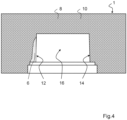
- Fig. 4 shows the molded part 10 with the embedded molding compound 6 after these measures have been carried out.
- the molding material 8 forms a second delimiting region 14 adjacent to the first delimiting region 12 and preferably adjoining thereto.
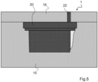
- the first molded part 10 (including the molding compound 6 defining the first boundary area) is joined as article 1 with another molded part 18 to form a complete casting mold.
- the two molded parts 10 and 18 are rotated by 180° in the embodiment of the method according to the invention shown.
- the molded part 18 thus now forms the top of the article 1.
- a cast metal 22 is then poured into the cavity 16 of the article 1, which is preferably designed as a casting mold, via a sprue 20 formed in the molded part 18 or subsequently created in the molded part 18. This cast metal 22 completely fills the cavity 16 and rises up into the sprue 22.
Landscapes
- Engineering & Computer Science (AREA)
- Chemical & Material Sciences (AREA)
- Mechanical Engineering (AREA)
- Materials Engineering (AREA)
- Chemical Kinetics & Catalysis (AREA)
- Mold Materials And Core Materials (AREA)
- Molds, Cores, And Manufacturing Methods Thereof (AREA)
Applications Claiming Priority (2)
| Application Number | Priority Date | Filing Date | Title |
|---|---|---|---|
| DE102020131492.2A DE102020131492A1 (de) | 2020-11-27 | 2020-11-27 | Herstellverfahren, Gießformen, Kerne oder Speiser sowie Kit und Verfahren zur Herstellung eines metallischen Gussteils. |
| PCT/EP2021/083204 WO2022112515A1 (de) | 2020-11-27 | 2021-11-26 | HERSTELLVERFAHREN, GIEßFORMEN, KERNE ODER SPEISER SOWIE KIT UND VERFAHREN ZUR HERSTELLUNG EINES METALLISCHEN GUSSTEILS |
Publications (3)
| Publication Number | Publication Date |
|---|---|
| EP4251344A1 EP4251344A1 (de) | 2023-10-04 |
| EP4251344C0 EP4251344C0 (de) | 2024-10-02 |
| EP4251344B1 true EP4251344B1 (de) | 2024-10-02 |
Family
ID=78822674
Family Applications (1)
| Application Number | Title | Priority Date | Filing Date |
|---|---|---|---|
| EP21820240.6A Active EP4251344B1 (de) | 2020-11-27 | 2021-11-26 | Herstellverfahren für giessformen, kerne oder speiser |
Country Status (10)
| Country | Link |
|---|---|
| US (1) | US12059724B2 (enExample) |
| EP (1) | EP4251344B1 (enExample) |
| JP (1) | JP2023553338A (enExample) |
| KR (1) | KR20230112675A (enExample) |
| CN (1) | CN116568425A (enExample) |
| DE (1) | DE102020131492A1 (enExample) |
| ES (1) | ES2995490T3 (enExample) |
| MX (1) | MX2023006202A (enExample) |
| PL (1) | PL4251344T3 (enExample) |
| WO (1) | WO2022112515A1 (enExample) |
Families Citing this family (1)
| Publication number | Priority date | Publication date | Assignee | Title |
|---|---|---|---|---|
| CN115889679A (zh) * | 2022-11-22 | 2023-04-04 | 新江科技(江苏)有限公司 | 一种镁合金铸造用高透气性湿型砂及其制备方法 |
Family Cites Families (20)
| Publication number | Priority date | Publication date | Assignee | Title |
|---|---|---|---|---|
| GB1029057A (en) | 1963-06-24 | 1966-05-11 | Fullers Earth Union Ltd | Foundry sand compositions |
| US3273211A (en) | 1963-11-29 | 1966-09-20 | Archer Daniels Midland Co | Process of molding exothermic compositions |
| JPS5586642A (en) * | 1978-12-26 | 1980-06-30 | Dainippon Ink & Chem Inc | Composition for organic self-hardening mold |
| BR9601454C1 (pt) | 1996-03-25 | 2000-01-18 | Paulo Roberto Menon | Processo para produção de luvas exotérmicas e isolantes. |
| DE19617938A1 (de) | 1996-04-27 | 1997-11-06 | Chemex Gmbh | Speisereinsätze und deren Herstellung |
| ES2134729B1 (es) | 1996-07-18 | 2000-05-16 | Kemen Recupac Sa | Mejoras introducidas en objeto solicitud patente invencion española n. 9601607 por "procedimiento para fabricacion manguitos exactos y otros elementos de mazarotaje y alimentacion para moldes de fundicion, incluyendo la formulacion para obtencion de dichos manguitos y elementos". |
| DE19920570B4 (de) | 1999-05-04 | 2008-01-10 | Chemex Gmbh | Formbare exotherme Zusammensetzungen und Speiser daraus |
| DE10065270B4 (de) | 2000-12-29 | 2006-04-20 | Chemex Gmbh | Speiser und Zusammensetzungen zu deren Herstellung |
| DE10104289B4 (de) | 2001-01-30 | 2004-11-11 | Chemex Gmbh | Formbare exotherme Zusammensetzungen und Speiser daraus |
| JPWO2005053876A1 (ja) * | 2003-12-05 | 2007-06-28 | 明和化学工業株式会社 | 鋳物用発熱体成形材料、鋳物用発熱体、およびそれらの製造方法 |
| DE102005025771B3 (de) | 2005-06-04 | 2006-12-28 | Chemex Gmbh | Isolierender Speiser und Verfahren zu dessen Herstellung |
| DE102007012660B4 (de) | 2007-03-16 | 2009-09-24 | Chemex Gmbh | Kern-Hülle-Partikel zur Verwendung als Füllstoff für Speisermassen |
| DE102012200967A1 (de) | 2012-01-24 | 2013-07-25 | Chemex Gmbh | Speiser und formbare Zusammensetzung zu deren Herstellung enthaltend kalzinierte Kieselgur |
| DE102016202795A1 (de) | 2016-02-23 | 2017-08-24 | HÜTTENES-ALBERTUS Chemische Werke Gesellschaft mit beschränkter Haftung | Verwendung einer Zusammensetzung als Bindemittelkomponente zur Herstellung von Speiserelementen nach dem Cold-Box-Verfahren, entsprechende Verfahren und Speiserelemente |
| DE102016203896A1 (de) | 2016-03-09 | 2017-09-14 | HÜTTENES-ALBERTUS Chemische Werke Gesellschaft mit beschränkter Haftung | Zweikomponenten-Bindemittelsystem für den Polyurethan-Cold-Box-Prozess |
| DE102016205960A1 (de) | 2016-04-08 | 2017-10-12 | HÜTTENES-ALBERTUS Chemische Werke Gesellschaft mit beschränkter Haftung | Verwendung von geschlossen-porigen Mikro-Kugeln aus expandiertem Perlit als Füllstoff für die Herstellung von Formkörpern für die Gießereiindustrie |
| DE102017217096B3 (de) | 2016-12-06 | 2018-03-22 | Wolfram Bach | Werkzeugeinsatz, Form- oder Kernwerkzeug sowie Verfahren zur Herstellung von Formen oder Kernen |
| CN108687301B (zh) * | 2017-04-06 | 2020-01-10 | 济南圣泉集团股份有限公司 | 铸造用粘结剂组合物及用于制备它的套组 |
| DE102017107531A1 (de) | 2017-04-07 | 2018-10-11 | HÜTTENES-ALBERTUS Chemische Werke Gesellschaft mit beschränkter Haftung | Verfahren zur Herstellung von Gießformen, Kernen und daraus regenerierten Formgrundstoffen |
| WO2019208322A1 (ja) * | 2018-04-26 | 2019-10-31 | Dic株式会社 | 結合剤、その製造方法および鋳造用砂型の製造方法 |
-
2020
- 2020-11-27 DE DE102020131492.2A patent/DE102020131492A1/de active Pending
-
2021
- 2021-11-26 MX MX2023006202A patent/MX2023006202A/es unknown
- 2021-11-26 KR KR1020237020970A patent/KR20230112675A/ko active Pending
- 2021-11-26 JP JP2023532154A patent/JP2023553338A/ja active Pending
- 2021-11-26 EP EP21820240.6A patent/EP4251344B1/de active Active
- 2021-11-26 WO PCT/EP2021/083204 patent/WO2022112515A1/de not_active Ceased
- 2021-11-26 ES ES21820240T patent/ES2995490T3/es active Active
- 2021-11-26 PL PL21820240.6T patent/PL4251344T3/pl unknown
- 2021-11-26 US US18/039,115 patent/US12059724B2/en active Active
- 2021-11-26 CN CN202180079771.2A patent/CN116568425A/zh active Pending
Also Published As
| Publication number | Publication date |
|---|---|
| US12059724B2 (en) | 2024-08-13 |
| JP2023553338A (ja) | 2023-12-21 |
| ES2995490T3 (en) | 2025-02-10 |
| DE102020131492A1 (de) | 2022-06-02 |
| EP4251344C0 (de) | 2024-10-02 |
| CN116568425A (zh) | 2023-08-08 |
| KR20230112675A (ko) | 2023-07-27 |
| WO2022112515A1 (de) | 2022-06-02 |
| US20240001433A1 (en) | 2024-01-04 |
| PL4251344T3 (pl) | 2025-02-24 |
| MX2023006202A (es) | 2023-08-16 |
| EP4251344A1 (de) | 2023-10-04 |
Similar Documents
| Publication | Publication Date | Title |
|---|---|---|
| EP0711213B1 (de) | Verfahren für den einsatz in der giessereitechnik | |
| EP2323783B1 (de) | Mit wasserglas beschichteter und/oder vermischter kern- oder formsand mit einem wassergehalt im bereich von > etwa 0,25 gew.-% bis etwa 0,9 gew.-% | |
| EP1633509B1 (de) | Verfahren zum schichtweisen aufbau von modellen | |
| DE69725315T2 (de) | Verfahren zur herstellung von speisern und anderen beschickungs- und zuführungs-elementen für giessformen und zusammensetzung zur herstellung der speiser und elemente | |
| DE69716248T2 (de) | Hülsen, deren herstellung und verwendung | |
| DE60123476T2 (de) | Form zum metallgiessen | |
| EP1227908A1 (de) | Verfahren und vorrichtung zur herstellung von gitternetzstrukturen | |
| EP4251344B1 (de) | Herstellverfahren für giessformen, kerne oder speiser | |
| DE60220841T2 (de) | Hülse, herstellungsverfahren derselben und gemisch zur herstellung derselben | |
| DE69803237T2 (de) | Verfahren zur Herstellung eines exothermen Körpers für Giessereizwecke | |
| DE2824773A1 (de) | Zusammensetzung fuer die auskleidung eines verteilers zum giessen | |
| EP1425121B1 (de) | Verfahren zum herstellen von gussstücken, formsand und seine verwendung für die durchführung des verfahrens | |
| DE29611969U1 (de) | Formkörper | |
| DE102012022331A1 (de) | Salzkern und Herstellverfahren dafür | |
| DE60020858T2 (de) | Verfahren und vorrichtung zum giessen | |
| WO2006058664A2 (de) | Verwendung von schwerlöslichen salzen in kombination mit wasserglas im rahmen der herstellung von formen und kernen für die giessereitechmik | |
| EP1620216B1 (de) | Formstoff, formteil und verfahren zur herstellung von formteilen für eine giessform | |
| CN117125964B (zh) | 一种基于3d打印技术的陶瓷铸型的制备方法 | |
| DE102018114700B3 (de) | Verwendung eines Verfahrens zur Herstellung eines Werkzeugs für die Aluminiumblech-Umformung | |
| DE102018119392A1 (de) | Verfahren zur Herstellung von Gegenständen aus Wachs | |
| DE1965446C (de) | Verfahren zum Herstellen einer mehr schichtigen Gießform fur den Femguß mit Dauermodellen | |
| DE3616049A1 (de) | Am-msgt-verfahren fuer die herstellung von industriellen modellen, formen, matrizen, kokillen, vorrichtungsausruestungen und spezialwerkzeugen | |
| WO2009121611A1 (de) | Giessform zur herstellung eines gussbauteils und verfahren zur herstellung einer giessform | |
| DE102006022594A1 (de) | Formwerkzeug zur Herstellung eines Schaumteiles und Verfahren zur Herstellung des Formwerkzeuges | |
| EP0945200A1 (de) | Giessform und Verfahren zu deren Herstellung |
Legal Events
| Date | Code | Title | Description |
|---|---|---|---|
| STAA | Information on the status of an ep patent application or granted ep patent |
Free format text: STATUS: UNKNOWN |
|
| STAA | Information on the status of an ep patent application or granted ep patent |
Free format text: STATUS: THE INTERNATIONAL PUBLICATION HAS BEEN MADE |
|
| PUAI | Public reference made under article 153(3) epc to a published international application that has entered the european phase |
Free format text: ORIGINAL CODE: 0009012 |
|
| STAA | Information on the status of an ep patent application or granted ep patent |
Free format text: STATUS: REQUEST FOR EXAMINATION WAS MADE |
|
| 17P | Request for examination filed |
Effective date: 20230627 |
|
| AK | Designated contracting states |
Kind code of ref document: A1 Designated state(s): AL AT BE BG CH CY CZ DE DK EE ES FI FR GB GR HR HU IE IS IT LI LT LU LV MC MK MT NL NO PL PT RO RS SE SI SK SM TR |
|
| DAV | Request for validation of the european patent (deleted) | ||
| DAX | Request for extension of the european patent (deleted) | ||
| STAA | Information on the status of an ep patent application or granted ep patent |
Free format text: STATUS: EXAMINATION IS IN PROGRESS |
|
| GRAP | Despatch of communication of intention to grant a patent |
Free format text: ORIGINAL CODE: EPIDOSNIGR1 |
|
| STAA | Information on the status of an ep patent application or granted ep patent |
Free format text: STATUS: GRANT OF PATENT IS INTENDED |
|
| RIC1 | Information provided on ipc code assigned before grant |
Ipc: B22C 1/22 20060101ALI20240403BHEP Ipc: B22C 1/18 20060101ALI20240403BHEP Ipc: B22C 1/02 20060101ALI20240403BHEP Ipc: B22C 9/10 20060101ALI20240403BHEP Ipc: B22C 9/08 20060101ALI20240403BHEP Ipc: B22C 9/02 20060101AFI20240403BHEP |
|
| INTG | Intention to grant announced |
Effective date: 20240508 |
|
| GRAS | Grant fee paid |
Free format text: ORIGINAL CODE: EPIDOSNIGR3 |
|
| GRAA | (expected) grant |
Free format text: ORIGINAL CODE: 0009210 |
|
| STAA | Information on the status of an ep patent application or granted ep patent |
Free format text: STATUS: THE PATENT HAS BEEN GRANTED |
|
| AK | Designated contracting states |
Kind code of ref document: B1 Designated state(s): AL AT BE BG CH CY CZ DE DK EE ES FI FR GB GR HR HU IE IS IT LI LT LU LV MC MK MT NL NO PL PT RO RS SE SI SK SM TR |
|
| REG | Reference to a national code |
Ref country code: GB Ref legal event code: FG4D Free format text: NOT ENGLISH |
|
| REG | Reference to a national code |
Ref country code: CH Ref legal event code: EP |
|
| REG | Reference to a national code |
Ref country code: IE Ref legal event code: FG4D Free format text: LANGUAGE OF EP DOCUMENT: GERMAN |
|
| REG | Reference to a national code |
Ref country code: DE Ref legal event code: R096 Ref document number: 502021005364 Country of ref document: DE |
|
| U01 | Request for unitary effect filed |
Effective date: 20241002 |
|
| U07 | Unitary effect registered |
Designated state(s): AT BE BG DE DK EE FI FR IT LT LU LV MT NL PT RO SE SI Effective date: 20241025 |
|
| U20 | Renewal fee for the european patent with unitary effect paid |
Year of fee payment: 4 Effective date: 20241105 |
|
| REG | Reference to a national code |
Ref country code: ES Ref legal event code: FG2A Ref document number: 2995490 Country of ref document: ES Kind code of ref document: T3 Effective date: 20250210 |
|
| PG25 | Lapsed in a contracting state [announced via postgrant information from national office to epo] |
Ref country code: HR Free format text: LAPSE BECAUSE OF FAILURE TO SUBMIT A TRANSLATION OF THE DESCRIPTION OR TO PAY THE FEE WITHIN THE PRESCRIBED TIME-LIMIT Effective date: 20241002 Ref country code: IS Free format text: LAPSE BECAUSE OF FAILURE TO SUBMIT A TRANSLATION OF THE DESCRIPTION OR TO PAY THE FEE WITHIN THE PRESCRIBED TIME-LIMIT Effective date: 20250202 |
|
| PG25 | Lapsed in a contracting state [announced via postgrant information from national office to epo] |
Ref country code: NO Free format text: LAPSE BECAUSE OF FAILURE TO SUBMIT A TRANSLATION OF THE DESCRIPTION OR TO PAY THE FEE WITHIN THE PRESCRIBED TIME-LIMIT Effective date: 20250102 |
|
| PG25 | Lapsed in a contracting state [announced via postgrant information from national office to epo] |
Ref country code: GR Free format text: LAPSE BECAUSE OF FAILURE TO SUBMIT A TRANSLATION OF THE DESCRIPTION OR TO PAY THE FEE WITHIN THE PRESCRIBED TIME-LIMIT Effective date: 20250103 |
|
| PG25 | Lapsed in a contracting state [announced via postgrant information from national office to epo] |
Ref country code: CZ Free format text: LAPSE BECAUSE OF FAILURE TO SUBMIT A TRANSLATION OF THE DESCRIPTION OR TO PAY THE FEE WITHIN THE PRESCRIBED TIME-LIMIT Effective date: 20241002 |
|
| PG25 | Lapsed in a contracting state [announced via postgrant information from national office to epo] |
Ref country code: RS Free format text: LAPSE BECAUSE OF FAILURE TO SUBMIT A TRANSLATION OF THE DESCRIPTION OR TO PAY THE FEE WITHIN THE PRESCRIBED TIME-LIMIT Effective date: 20250102 |
|
| REG | Reference to a national code |
Ref country code: CH Ref legal event code: PL |
|
| PG25 | Lapsed in a contracting state [announced via postgrant information from national office to epo] |
Ref country code: SM Free format text: LAPSE BECAUSE OF FAILURE TO SUBMIT A TRANSLATION OF THE DESCRIPTION OR TO PAY THE FEE WITHIN THE PRESCRIBED TIME-LIMIT Effective date: 20241002 |
|
| PG25 | Lapsed in a contracting state [announced via postgrant information from national office to epo] |
Ref country code: MC Free format text: LAPSE BECAUSE OF FAILURE TO SUBMIT A TRANSLATION OF THE DESCRIPTION OR TO PAY THE FEE WITHIN THE PRESCRIBED TIME-LIMIT Effective date: 20241002 |
|
| REG | Reference to a national code |
Ref country code: CH Ref legal event code: PL |
|
| PG25 | Lapsed in a contracting state [announced via postgrant information from national office to epo] |
Ref country code: CH Free format text: LAPSE BECAUSE OF NON-PAYMENT OF DUE FEES Effective date: 20241130 |
|
| PG25 | Lapsed in a contracting state [announced via postgrant information from national office to epo] |
Ref country code: SK Free format text: LAPSE BECAUSE OF FAILURE TO SUBMIT A TRANSLATION OF THE DESCRIPTION OR TO PAY THE FEE WITHIN THE PRESCRIBED TIME-LIMIT Effective date: 20241002 |
|
| PLBE | No opposition filed within time limit |
Free format text: ORIGINAL CODE: 0009261 |
|
| STAA | Information on the status of an ep patent application or granted ep patent |
Free format text: STATUS: NO OPPOSITION FILED WITHIN TIME LIMIT |
|
| 26N | No opposition filed |
Effective date: 20250703 |
|
| PGFP | Annual fee paid to national office [announced via postgrant information from national office to epo] |
Ref country code: PL Payment date: 20250918 Year of fee payment: 5 |
|
| PG25 | Lapsed in a contracting state [announced via postgrant information from national office to epo] |
Ref country code: IE Free format text: LAPSE BECAUSE OF NON-PAYMENT OF DUE FEES Effective date: 20241126 |
|
| U20 | Renewal fee for the european patent with unitary effect paid |
Year of fee payment: 5 Effective date: 20250917 |
|
| PGFP | Annual fee paid to national office [announced via postgrant information from national office to epo] |
Ref country code: GB Payment date: 20251120 Year of fee payment: 5 |
|
| PGFP | Annual fee paid to national office [announced via postgrant information from national office to epo] |
Ref country code: TR Payment date: 20251120 Year of fee payment: 5 |
|
| PGFP | Annual fee paid to national office [announced via postgrant information from national office to epo] |
Ref country code: ES Payment date: 20251216 Year of fee payment: 5 |
|
| PG25 | Lapsed in a contracting state [announced via postgrant information from national office to epo] |
Ref country code: HU Free format text: LAPSE BECAUSE OF FAILURE TO SUBMIT A TRANSLATION OF THE DESCRIPTION OR TO PAY THE FEE WITHIN THE PRESCRIBED TIME-LIMIT; INVALID AB INITIO Effective date: 20211126 |
|
| PG25 | Lapsed in a contracting state [announced via postgrant information from national office to epo] |
Ref country code: CY Free format text: LAPSE BECAUSE OF FAILURE TO SUBMIT A TRANSLATION OF THE DESCRIPTION OR TO PAY THE FEE WITHIN THE PRESCRIBED TIME-LIMIT; INVALID AB INITIO Effective date: 20211126 |