EP4248873A1 - Computertomographiegerät und verfahren zur energieübertragung in einem computertomographiegerät - Google Patents
Computertomographiegerät und verfahren zur energieübertragung in einem computertomographiegerät Download PDFInfo
- Publication number
- EP4248873A1 EP4248873A1 EP22192948.2A EP22192948A EP4248873A1 EP 4248873 A1 EP4248873 A1 EP 4248873A1 EP 22192948 A EP22192948 A EP 22192948A EP 4248873 A1 EP4248873 A1 EP 4248873A1
- Authority
- EP
- European Patent Office
- Prior art keywords
- rotor
- connecting element
- energy
- gantry part
- supporting
- Prior art date
- Legal status (The legal status is an assumption and is not a legal conclusion. Google has not performed a legal analysis and makes no representation as to the accuracy of the status listed.)
- Granted
Links
Images





Classifications
-
- A—HUMAN NECESSITIES
- A61—MEDICAL OR VETERINARY SCIENCE; HYGIENE
- A61B—DIAGNOSIS; SURGERY; IDENTIFICATION
- A61B6/00—Apparatus or devices for radiation diagnosis; Apparatus or devices for radiation diagnosis combined with radiation therapy equipment
- A61B6/02—Arrangements for diagnosis sequentially in different planes; Stereoscopic radiation diagnosis
- A61B6/03—Computed tomography [CT]
- A61B6/032—Transmission computed tomography [CT]
-
- A—HUMAN NECESSITIES
- A61—MEDICAL OR VETERINARY SCIENCE; HYGIENE
- A61B—DIAGNOSIS; SURGERY; IDENTIFICATION
- A61B6/00—Apparatus or devices for radiation diagnosis; Apparatus or devices for radiation diagnosis combined with radiation therapy equipment
- A61B6/56—Details of data transmission or power supply, e.g. use of slip rings
-
- A—HUMAN NECESSITIES
- A61—MEDICAL OR VETERINARY SCIENCE; HYGIENE
- A61B—DIAGNOSIS; SURGERY; IDENTIFICATION
- A61B6/00—Apparatus or devices for radiation diagnosis; Apparatus or devices for radiation diagnosis combined with radiation therapy equipment
- A61B6/02—Arrangements for diagnosis sequentially in different planes; Stereoscopic radiation diagnosis
- A61B6/03—Computed tomography [CT]
- A61B6/032—Transmission computed tomography [CT]
- A61B6/035—Mechanical aspects of CT
-
- A—HUMAN NECESSITIES
- A61—MEDICAL OR VETERINARY SCIENCE; HYGIENE
- A61B—DIAGNOSIS; SURGERY; IDENTIFICATION
- A61B6/00—Apparatus or devices for radiation diagnosis; Apparatus or devices for radiation diagnosis combined with radiation therapy equipment
- A61B6/44—Constructional features of apparatus for radiation diagnosis
- A61B6/4405—Constructional features of apparatus for radiation diagnosis the apparatus being movable or portable, e.g. handheld or mounted on a trolley
Definitions
- a projection data acquisition system is rotated around an examination area in order to acquire projection data from the examination area for different projection directions.
- the projection data acquisition system is integrated into a rotating gantry part of the computer tomography device, which is rotatably mounted relative to a supporting gantry part of the computer tomography device.
- a continuous energy supply can be achieved, for example, by means of a slip ring arrangement, in which resilient sliding contacts are dragged along annular sliding tracks and thereby follow a rotational movement of the rotating gantry part relative to the supporting gantry part.
- Another possibility for continuously transmitting electrical energy from the supporting gantry part to the rotating gantry part is based on a contactless rotary connection, for example based on inductive, capacitive and/or electromagnetic coupling with at least one annular conductor arrangement.
- Annular sliding tracks and/or coupling conductors can limit the flexibility with which installation space in the computer tomography device, in particular on the rotor, is available for other components.
- the wear of sliding contacts means increased maintenance costs.
- the manufacturing effort is relatively high for contactless slewing rings, especially in relation to the gap between the rotating gantry part and the supporting gantry part in the area of the contactless rotary connection.
- US 8,218,726 B2 and US 10 342 506 B2 each disclose a computer tomography device with an energy storage device.
- the invention has the task of providing an alternative to conventional energy transmission solutions for computer tomography devices.
- the invention relates to a computer tomography device, having a gantry with a supporting gantry part and a rotor, the rotor having a projection data acquisition system and an energy storage for supplying energy to the projection data acquisition system and being rotatably mounted relative to the supporting gantry part, the gantry having an energy transmission system which is for Energy transmission from the supporting gantry part to the energy storage of the rotor is set up, the rotor resting relative to the supporting gantry part during the energy transfer from the supporting gantry part to the energy storage of the rotor.
- the gantry of the computer tomography device can in particular have a connection for receiving electrical energy.
- the electrical energy can be provided, for example, by an electrical energy transmission network, in particular by a low-voltage network of a clinic.
- the connection for receiving the electrical energy can in particular be set up for detachable connection to the electrical energy transmission network, for example by means of a connecting cable.
- the energy transfer from the supporting gantry part to the energy storage of the rotor can take place in such a way that electrical energy is stored in the Energy storage of the rotor takes place.
- the energy storage of the rotor can in particular be set up to supply energy to the projection data acquisition system in such a way that the projection data acquisition system can be supplied with electrical energy from the energy storage of the rotor while the rotor rotates relative to the supporting gantry part.
- the energy storage of the rotor can be based, for example, on an accumulator and/or on capacitors, in particular supercapacitors.
- Supercapacitors are also known as electrochemical capacitor, ultracapacitor, ultracap and supercap.
- the projection data acquisition system can, for example, have an X-ray source and/or an X-ray detector, which interacts with the X-ray source, and/or can be set up to acquire projection data. Acquiring the projection data using the projection data acquisition system can in particular include generating x-rays using the x-ray source and detecting the x-rays using the x-ray detector.
- a medical imaging device comprising a gantry with a supporting gantry part and a movable gantry part, the movable gantry part having a projection data acquisition system and an energy storage for supplying energy to the projection data acquisition system and being movably mounted relative to the supporting gantry part, the gantry having an energy transmission system , which is responsible for energy transfer from the supporting gantry part to the energy storage of the movable gantry part, wherein during the energy transfer from the supporting gantry part to the energy storage of the movable gantry part, the movable gantry part rests relative to the supporting gantry part.
- the energy transmission system is further set up for an energy transfer from the energy storage of the movable gantry part to the supporting gantry part, the movable gantry part resting relative to the supporting gantry part during the energy transfer from the energy storage of the movable gantry part to the supporting gantry part.
- the medical imaging device can be a C-arm X-ray device, wherein the movable gantry part is a C-arm of the C-arm X-ray device.
- the medical imaging device can be further developed with suitable features that are described in relation to the rotor of the gantry of the computer tomography device by replacing the reference to the rotor of the gantry of the computer tomography device with a reference to the movable gantry part of the medical imaging device.
- the computer tomography device can in particular be a mobile computer tomography device or a stationary computer tomography device.
- the computer tomography device can in particular be designed as a head computer tomography device for head imaging, for example as a mobile head computer tomography device.
- the gantry can in particular have an opening.
- the opening can, for example, be designed in such a way that an examination object can be introduced into the opening along a system axis of the gantry for an examination using the computer tomography device.
- the examination object can be, for example, a human, an animal or a phantom.
- the rotor can be in particular relative to the supporting one Gantry part can be mounted rotatably about an axis of rotation.
- the axis of rotation can, for example, be equal to the system axis.
- the computer tomography device can thus be operated in such a way that energy is transferred between the rotor and the supporting gantry part only in a resting state of the rotor relative to the supporting gantry part, in particular between two operating states of the computer tomography device in which the rotor rotates relative to the supporting gantry part .
- a continuous energy transfer during rotation of the rotor relative to the supporting gantry part is therefore not necessary. Therefore, ring-shaped sliding tracks and coupling conductors can be dispensed with.
- the effort for production and maintenance can be reduced and the installation space in the computer tomography device can be used more flexibly. Furthermore, material costs and weight of the computer tomography device can be reduced in this way.
- the energy transmission system is further set up for energy transmission from the energy storage of the rotor to the supporting gantry part, the rotor resting relative to the supporting gantry part during the energy transfer from the energy storage of the rotor to the supporting gantry part.
- the rotor's energy storage can be used to supply energy to the entire computer tomography device while the rotor is at rest relative to the supporting gantry part.
- the gantry has a chassis which is set up for a travel movement of the gantry relative to a base area, with the energy being transferred from the energy storage of the rotor to the supporting gantry part during the travel movement of the gantry.
- the base area can, for example, be a floor of an examination room and/or a floor covering and/or a base must be formed.
- the chassis can in particular be set up to move the gantry parallel to the base area relative to the base area.
- the chassis can, for example, be based on wheels and/or omnidirectional.
- the travel movement of the gantry can take place in particular while the rotor is at rest relative to the supporting gantry part.
- the travel movement of the gantry can take place, for example, in order to move the gantry within an examination room and/or between different examination rooms in a clinic.
- the travel movement of the gantry can take place in particular while the gantry is separated from an electrical energy transmission network, in particular from a low-voltage network of a clinic.
- the supporting gantry part has an electric travel drive that interacts with the chassis, wherein the energy is transferred from the energy storage of the rotor to the supporting gantry part by means of the energy transmission system from the energy storage of the rotor to the electric travel drive in order to achieve the travel movement to drive the gantry using the travel drive.
- the supporting gantry part has an energy storage, with the energy transmission from the supporting gantry part to the energy storage of the rotor by means of the energy transmission system from the energy storage of the supporting gantry part to the energy storage of the rotor and/or wherein the energy transfer from the energy storage of the rotor to the supporting gantry part takes place by means of the energy transmission system from the energy storage of the rotor to the energy storage of the supporting gantry part.
- the energy is transferred from the energy storage of the supporting gantry part to the energy storage of the rotor during the travel movement of the gantry.
- the energy storage of the supporting gantry part can be used to supply energy to components of the supporting gantry part while the rotor rotates relative to the supporting gantry part and/or while the energy storage of the rotor is not connected to the supporting gantry part via the energy transfer system.
- the chassis can, for example, be set up for a scanning movement of the gantry relative to the examination object while acquiring the projection data.
- the examination object can rest relative to the base area.
- the scanning movement of the gantry can take place in particular along the system axis of the gantry.
- the scanning movement can be driven, for example, based on electrical energy from the energy storage of the supporting gantry part.
- the gantry in particular the energy transmission system of the gantry, can have a switching device, for example.
- the switching device can, for example, be set up to distribute electrical energy to the energy storage of the supporting gantry part and the energy storage of the rotor.
- the switching device can be set up, for example, to switch the computer tomography device into different operating states that differ from one another with regard to the flow of electrical energy.
- the supporting gantry part has a data processing system, wherein the energy storage of the supporting gantry part is set up to supply energy to the data processing system, the data processing system being supplied with electrical energy from the energy storage of the supporting gantry part, in particular while the rotor is moving relative to the supporting gantry part rotates.
- the data processing system can be set up, for example, to control the computer tomography device and/or to image process the projection data.
- the supporting gantry part has a first connecting element of the energy transmission system, that the rotor has a second connecting element of the energy transmission system and that the first connecting element and the second connecting element are designed to correspond to one another for establishing an energy transmission connection.
- the first connecting element and the second connecting element are aligned correspondingly to one another for establishing the energy transmission connection when the rotor is in a coupling angular position relative to the supporting gantry part.
- the gantry has an angular positioning device, wherein the angular positioning device is set up for angular positioning of the rotor in the coupling angular position relative to the supporting gantry part.
- the energy is transferred from the supporting gantry part to the energy storage of the rotor by means of the energy transmission connection and/or that the energy is transferred from the energy storage of the rotor to the supporting gantry part by means of the energy transfer connection.
- the energy transmission connection can in particular be bidirectional.
- the rotor during the energy transfer from the supporting gantry part to the energy storage of the rotor, the rotor is at rest relative to the supporting gantry part and is in the coupling angular position relative to the supporting gantry part and / or that during the energy transfer from the energy storage of the Rotor to the supporting gantry part, the rotor rests relative to the supporting gantry part and is in the coupling angular position relative to the supporting gantry part.
- the coupling angular position can, for example, be related to the axis of rotation about which the rotor is rotatably mounted relative to the supporting gantry part.
- the coupling angular position can, for example, be that angular position of the rotor relative to the supporting gantry part in which a distance between the first connecting element and the second connecting element compared to other angular positions of the rotor relative to the supporting gantry part, which occur when the rotor rotates relative to the load-bearing gantry part is minimal.
- the gantry has an angular positioning device, wherein the angular positioning device is set up for angular positioning of the rotor in the coupling angular position relative to the supporting gantry part.
- the angular positioning of the rotor can, for example, be based on braking a rotational movement of the rotor relative to the supporting gantry part by means of a brake in such a way that the rotational movement of the rotor ends in the coupling angular position relative to the supporting gantry part.
- the angular positioning device can have the brake, for example.
- the angle positioning device can for example, be set up to drive an angular positioning rotational movement of the rotor relative to the supporting gantry part.
- Braking the rotational movement of the rotor, in particular the angular positioning rotational movement of the rotor, and/or driving the rotational movement of the rotor, in particular the angular positioning rotational movement of the rotor can be done, for example, with electrical energy from the energy storage of the rotor and/or with electrical energy from the energy storage of the load-bearing gantry part.
- the angular positioning device can, for example, have a fixing device which is set up to fix the rotor relative to the supporting gantry part in the coupling angular position relative to the supporting gantry part.
- the angular positioning device can, for example, have a spring-loaded bolt on the supporting gantry part and a hole on the rotor, which are designed and arranged such that the bolt can snap into the hole when the rotor is in the coupling angular position relative to the supporting gantry part , and thus can fix the rotor in the coupling angular position relative to the supporting gantry part.
- the energy transmission connection is an electrical plug-in connection between the first connecting element and the second connecting element.
- the energy transmission connection is set up for contactless electrical energy transmission between the first connecting element and the second connecting element, for example for contactless inductive electrical energy transmission between the first connecting element and the second connecting element and/or for contactless capacitive electrical energy transmission is set up between the first connecting element and the second connecting element.
- the energy transfer from the supporting gantry part to the energy storage of the rotor includes the contactless electrical energy transfer between the first connecting element and the second connecting element and/or that the energy transfer from the energy storage of the rotor to the supporting gantry part includes the contactless electrical energy transfer between the first connecting element and the second connecting element.
- the contactless electrical energy transfer between the first connecting element and the second connecting element can be implemented in a low-wear manner and/or can be used to electrically isolate the rotor from the supporting gantry part.
- the contactless electrical energy transfer between the first connecting element and the second connecting element can also take place while the rotor rotates relative to the supporting gantry part.
- the gantry has a coupling device which is used to arrange the first connecting element and the second connecting element in a coupling position relative to one another while the rotor rests relative to the supporting gantry part, in particular while the rotor is in the coupling angular position relative to the supporting gantry part, and for arranging the first connecting element and the second connecting element in a decoupling position relative to one another while the rotor rests relative to the supporting gantry part, in particular while the rotor rests in the coupling angular position relative to the supporting gantry part, is set up.
- the energy transmission connection is established by coupling the first connecting element and the second connecting element to one another when the rotor is in the coupling angular position relative to the supporting gantry part and when the first connecting element and the second connecting element are in the coupling angular position. Position are arranged relative to each other.
- the coupling of the first connecting element and the second connecting element to one another can be, for example, inductive and/or capacitive or based on an electrical contact, for example a spring-loaded and/or plugged-in electrical contact, of the first connecting element and the second connecting element to one another.
- the energy transmission connection is interrupted by decoupling the first connecting element and the second connecting element from one another when the first connecting element and the second connecting element are arranged in the decoupling position relative to one another.
- the coupling can be electrical and/or mechanical, for example.
- the decoupling can be electrical and/or mechanical, for example.
- the first connecting element and the second connecting element can be decoupled from one another, for example, by opening and/or enlarging a gap between the first connecting element and the second connecting element. By opening and/or enlarging the gap, for example, a rotation of the rotor relative to the supporting gantry part can be made possible without the rotation of the rotor being prevented and/or disturbed by the coupling of the first connecting element and the second connecting element to one another.
- the decoupling of the first Connecting element and the second connecting element can be done from one another by releasing the plug connection.
- Arranging the first connecting element and the second connecting element in the coupling position relative to one another and/or arranging the first connecting element and the second connecting element in the decoupling position relative to one another can be done, for example, with electrical energy from the energy storage of the rotor and/or with electrical Energy comes from the energy storage of the supporting gantry part.
- the energy transfer from the supporting gantry part to the energy storage of the rotor can be carried out in such a way that electrical energy is stored in the energy storage of the rotor.
- One embodiment provides that a travel movement of the gantry is carried out relative to a base area by means of a chassis, with the energy transfer from the energy storage of the rotor to the supporting gantry part being carried out during the travel movement of the gantry.
- One embodiment provides that by transferring energy from the energy storage of the rotor to the supporting gantry part by means of the energy transmission system, electrical energy for an electric drive that interacts with the chassis is transferred from the energy storage of the rotor to the supporting gantry part.
- the travel movement of the gantry can be driven by means of the electric travel drive based on the electrical energy for the electric travel drive.
- the supporting gantry part has an energy storage, wherein the energy transfer from the supporting gantry part to the energy storage of the rotor is carried out by means of the energy transfer system from the energy storage of the supporting gantry part to the energy storage of the rotor and/or the energy transfer from the energy storage of the rotor to the supporting gantry part is carried out by means of the energy transfer system from the energy storage of the rotor to the energy storage of the supporting gantry part.
- the supporting gantry part has a first connecting element of the energy transmission system, wherein the rotor has a second connecting element of the energy transmission system, wherein the first connecting element and the second connecting element are designed to correspond to one another for establishing an energy transmission connection.
- the rotor can be angularly positioned in a coupling angular position relative to the supporting gantry part, in particular angularly positioned by means of an angular positioning device, such that the first connecting element and the second Connecting element are aligned correspondingly to each other for establishing the energy transmission connection.
- the energy transmission connection is established by coupling the first connecting element and the second connecting element to one another, for example by arranging the first connecting element and the second connecting element in a coupling position relative to one another, in particular by means of a coupling device in the coupling position be arranged relative to each other while the rotor is at rest relative to the supporting gantry part and is in the coupling angular position relative to the supporting gantry part.
- the energy transmission connection is interrupted by decoupling the first connecting element and the second connecting element from each other, for example by arranging the first connecting element and the second connecting element in a decoupling position relative to one another, in particular by means of the coupling device in the decoupling position be arranged relative to each other while the rotor is at rest relative to the supporting gantry part and is in the coupling angular position relative to the supporting gantry part.
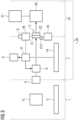
- the Fig. 1 shows an energy flow diagram for a first operating state of the computer tomography device.
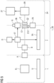
- the Fig. 2 shows an energy flow diagram for a second operating state of the computer tomography device.
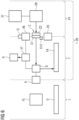
- the Fig. 3 shows an energy flow diagram for a third operating state of the computer tomography device.
- the Fig. 4 shows an energy flow diagram for a fourth operating state of the computer tomography device.
- the Fig. 5 shows an energy flow diagram for a fifth operating state of the computer tomography device.
- the Fig. 6 shows an energy flow diagram for an operating state of a computer tomography device according to a further example.
- the Fig. 7 shows an energy flow diagram for an operating state of a computer tomography device according to a further example.
- the Fig. 8 shows an example of a computer tomography device.
- the Fig. 9 shows a flowchart of a method for energy transmission in a computer tomography device.
- the Fig. 1 shows an energy flow diagram for a first operating state of the computer tomography device 1.
- the computer tomography device 1 has a gantry 20 with a supporting gantry part T and a rotor 24, the rotor 24 having a projection data acquisition system 27 and an energy storage ER for supplying energy to the projection data acquisition system 27 and relative to the supporting gantry part T is rotatably mounted, the gantry 20 having an energy transmission system C, which is set up for energy transmission from the supporting gantry part T to the energy storage ER of the rotor 24, during the energy transfer from the supporting gantry part T to the energy storage ER of the rotor 24 the rotor 24 rests relative to the supporting gantry part T.
- the rotor 24 rests relative to the supporting gantry part T, the energy transmission connection of the energy transmission system C being established between the energy storage ER of the rotor 24 and the supporting gantry part T.
- the gantry 20 of the computer tomography device 1 has a connection A for receiving electrical energy.
- the electrical energy is provided by an electrical energy transmission network EL, for example a low-voltage network of a clinic.
- the connection A is detachably connected to the electrical energy transmission network EL by means of a connection cable.
- the supporting gantry part T has an energy storage ET, wherein the energy is transferred from the supporting gantry part T to the energy storage ER of the rotor 24 by means of the energy transmission system C from the energy storage ET of the supporting gantry part T to the energy storage ER of the rotor 24 and/or wherein the Energy transfer from the energy storage ER of the rotor 24 to the supporting gantry part T by means of the energy transfer system C from the energy storage ER of the rotor 24 to the energy storage ET of the supporting gantry part T takes place.
- the supporting gantry part T has a data processing system D, the energy storage ET of the supporting gantry part T being set up to supply energy to the data processing system D, the data processing system D being supplied with electrical energy from the energy storage ET of the supporting gantry part T, in particular while the Rotor 24 rotates relative to the supporting gantry part T.
- the energy transmission system C has the switching device B.
- the electrical energy received from the electrical energy transmission network EL is distributed by means of the switching device B to the energy storage ET of the supporting gantry part T and the energy storage ER of the rotor 24.
- electrical energy is stored both in the energy storage ET of the supporting gantry part T and in the energy storage ER of the rotor 24.
- the supporting gantry part T has a first connecting element C1 of the energy transmission system C.
- the rotor 24 has a second connecting element C2 of the energy transmission system C.
- the first connecting element C1 and the second connecting element C2 are designed to correspond to one another for establishing an energy transmission connection.
- the first connecting element C1 and the second connecting element C2 are correspondingly aligned with each other for establishing the energy transfer connection when the rotor 24 is in a coupling angular position relative to the supporting gantry part T.
- the gantry 20 has the angular positioning device G, wherein the angular positioning device G is set up for angular positioning of the rotor 24 in the coupling angular position relative to the supporting gantry part T.
- the energy transmission connection can, for example, be an electrical plug-in connection between the first connecting element C1 and the second connecting element C2.
- the energy transmission connection can be set up, for example, for contactless electrical energy transmission between the first connecting element C1 and the second connecting element C2.
- the gantry 20 has a coupling device C12, which is for arranging the first connecting element C1 and the second connecting element C2 in a coupling position relative to each other while the rotor 24 is at rest relative to the supporting gantry part T, and for arranging the first connecting element C1 and the second connecting element C2 is set up in a decoupling position relative to one another, while the rotor 24 rests relative to the supporting gantry part T.
- the energy transmission connection is established by coupling the first connecting element C1 and the second connecting element C2 to each other when the rotor 24 is in the coupling angular position relative to the supporting gantry part T and when the first connecting element C1 and the second connecting element C2 are in the coupling angular position. Position are arranged relative to each other.
- the energy transmission connection is interrupted by decoupling the first connecting element C1 and the second connecting element C2 from one another when the first connecting element C1 and the second connecting element C2 are arranged in the decoupling position relative to one another.
- the energy transmission connection is established by coupling the first connecting element C1 and the second connecting element C2 to one another, in that the first connecting element C1 and the second connecting element C2 are arranged in a coupling position relative to one another by means of the coupling device C12.
- the rotor 24 rests relative to the supporting gantry part T and is in the coupling angular position relative to the supporting gantry part T.
- the Fig. 2 shows an energy flow diagram for a second operating state of the computer tomography device 1.
- the rotor 24 rotates relative to the supporting gantry part T, the energy transmission connection of the energy transmission system C being interrupted between the energy storage ER of the rotor 24 and the supporting gantry part T .
- the connection A is not connected to the electrical energy transmission network EL.
- Projection data is acquired using the projection data acquisition system 27, the projection data acquisition system 27 being supplied with electrical energy from the energy storage ER of the rotor 24.
- the gantry 20 has the rotary drive 26 for driving the rotary movement of the rotor 24 relative to the supporting gantry part T about the axis of rotation SA, the rotary drive 26 being supplied with electrical energy from the energy storage ET of the supporting gantry part T.
- the energy transmission connection is interrupted by decoupling the first connecting element C1 and the second connecting element C2 from each other by connecting the first connecting element C1 and the second connecting element C2 in one by means of the coupling device C12
- Decoupling position can be arranged relative to each other while the rotor 24 rests relative to the supporting gantry part T and is in the coupling angular position relative to the supporting gantry part T.
- the Fig. 3 shows an energy flow diagram for a third operating state of the computer tomography device 1.
- the rotor 24 rests relative to the supporting gantry part T, the energy transmission connection of the energy transmission system C being established between the energy storage ER of the rotor 24 and the supporting gantry part T.
- the connection A is not connected to the electrical energy transmission network EL.
- the energy storage ER of the rotor 24 can be charged with electrical energy from the energy storage ET of the supporting gantry part T.
- the rotor 24 is angularly positioned in the coupling angular position relative to the supporting gantry part T by means of the angular positioning device G in such a way that the first connecting element C1 and the second connecting element C2 are positioned relative to one another the establishment of the energy transmission connection are aligned accordingly.
- the energy transmission connection is established by coupling the first connecting element C1 and the second connecting element C2 to one another by connecting the first connecting element C1 and the second connecting element C2 by means of the coupling device C12 in the Coupling position can be arranged relative to each other while the rotor 24 rests relative to the supporting gantry part T and is in the coupling angular position relative to the supporting gantry part T.
- the Fig. 4 shows an energy flow diagram for a fourth operating state of the computer tomography device 1.
- the rotor 24 rests relative to the supporting gantry part T, the energy transmission connection of the energy transmission system C being established between the energy storage ER of the rotor 24 and the supporting gantry part T.
- the connection A is not connected to the electrical energy transmission network EL.
- the energy transmission system C is set up for energy transfer from the energy storage ER of the rotor 24 to the supporting gantry part T, with the rotor 24 resting relative to the supporting gantry part T during the energy transfer from the energy storage ER of the rotor 24 to the supporting gantry part T.
- the Fig. 5 shows an energy flow diagram for a fifth operating state of the computer tomography device 1.
- the rotor 24 rotates relative to the supporting gantry part T, the energy transmission connection of the energy transmission system C being interrupted between the energy storage ER of the rotor 24 and the supporting gantry part T .
- the connection A is not connected to the electrical energy transmission network EL.
- Projection data is acquired using the projection data acquisition system 27, the projection data acquisition system 27 being supplied with electrical energy from the energy storage ER of the rotor 24.
- the gantry 20 has the rotary drive 26 for driving the rotary movement of the rotor 24 relative to the supporting gantry part T about the axis of rotation SA, the rotary drive 26 being supplied with electrical energy from the energy storage ET of the supporting gantry part T.
- the gantry 20 has the chassis FW, which is set up for a scanning movement of the gantry 20 relative to the base area U.
- the supporting gantry part T has an electric travel drive FA, which interacts with the chassis FW.
- the scanning movement of the gantry 20 is driven relative to the base area U based on electrical energy from the energy storage ET of the supporting gantry part T by means of the travel drive FA.
- the Fig. 6 shows an energy flow diagram for an operating state of a computer tomography device 1 according to a further example.
- the rotor 24 rests relative to the supporting gantry part T, the energy transmission connection of the energy transmission system C being established between the energy storage ER of the rotor 24 and the supporting gantry part T and the connection A not being connected to the electrical energy transmission network EL.
- the gantry 20 has the chassis FW, which is set up for a travel movement of the gantry 20 relative to the base area U.
- the supporting gantry part T has an electric travel drive FA, which interacts with the chassis FW.
- a travel movement of the gantry 20 is carried out relative to the base area U by means of the chassis FW.
- the energy transfer from the energy storage ER of the rotor 24 to the supporting gantry part T takes place during the travel movement of the gantry 20.
- the energy transfer from the energy storage ER of the rotor 24 to the supporting gantry part T takes place by means of the energy transfer system C from the energy storage ER of the rotor 24 to the electric travel drive FA to drive the travel movement of the gantry 20 using the travel drive FA.
- the Fig. 7 shows an energy flow diagram for an operating state of a computer tomography device 1 according to a further example.
- the rotor 24 rotates relative to the supporting gantry part T, the energy transmission connection of the energy transmission system C being interrupted between the energy storage ER of the rotor 24 and the supporting gantry part T and the connection A not being connected to the electrical energy transmission network EL .
- Projection data is acquired using the projection data acquisition system 27, the projection data acquisition system 27 being supplied with electrical energy from the energy storage ER of the rotor 24.
- the gantry 20 has the rotary drive 26 for driving the rotary movement of the rotor 24 relative to the supporting gantry part T about the axis of rotation SA, the rotary drive 26 being supplied with electrical energy from the energy storage ER of the rotor 24.
- the Fig. 8 shows an example of a computer tomography device 1 with the gantry 20.
- the gantry 20 has a first gantry part 21 and a second gantry part 22, the first gantry part 21 having the rotatably mounted rotor 24 with the projection data acquisition system 27, the second gantry part 22 having at least one Section of the opening 9 has.
- the first gantry part 21 has the pivot bearing 25 and a support structure 26, the rotor 24 being connected to the support structure 26 by means of the pivot bearing 25 and relative is rotatably mounted to the support structure 26 about the axis of rotation SA, the axis of rotation SA being a system axis of the gantry 20.
- the first gantry part 21 is mounted movably relative to the second gantry part 22 in such a way that a translational movement of the first gantry part 21 can be carried out relative to the second gantry part 22 along the system axis of the gantry 20, while at the same time the second gantry part 22 is relative to the head shell 19 and rests relative to the at least a portion of the opening 9.
- the supporting gantry part T can, for example, have the second gantry part 22 and the support structure 26 of the first gantry part 21.
- the translational movement of the first gantry part 21 relative to the second gantry part 22 can be driven, for example, with electrical energy from the energy storage ET of the supporting gantry part T when the rotor 24 rotates relative to the supporting gantry part T.
- the translational movement of the first gantry part 21 relative to the second gantry part 22 can be driven, for example, with electrical energy from the energy storage ER of the rotor 24 when the rotor 24 is at rest relative to the supporting gantry part T.
- Computed tomography device 1 shown is a mobile head computed tomography device.
- the gantry 20 has the head shell 19 and the body support device 7.
- a human's head can rest on the head shell 19 while the human's head is in the opening 9 for head imaging.
- the body support device 7 can be used to support a shoulder area of the human while the human's head is in the opening 9 for head imaging and rests on the head shell 19.
- the gantry 20 also has a cladding V for delimiting an interior area of the gantry 20 from an environment L of the gantry 20.
- the computer tomography device 1 also has an operating system with a touch-sensitive screen 8, which is arranged on the gantry 20.
Landscapes
- Health & Medical Sciences (AREA)
- Life Sciences & Earth Sciences (AREA)
- Engineering & Computer Science (AREA)
- Medical Informatics (AREA)
- Optics & Photonics (AREA)
- Biomedical Technology (AREA)
- Biophysics (AREA)
- High Energy & Nuclear Physics (AREA)
- Veterinary Medicine (AREA)
- Nuclear Medicine, Radiotherapy & Molecular Imaging (AREA)
- Public Health (AREA)
- Pathology (AREA)
- Radiology & Medical Imaging (AREA)
- Physics & Mathematics (AREA)
- Heart & Thoracic Surgery (AREA)
- Molecular Biology (AREA)
- Surgery (AREA)
- Animal Behavior & Ethology (AREA)
- General Health & Medical Sciences (AREA)
- Pulmonology (AREA)
- Theoretical Computer Science (AREA)
- Computer Networks & Wireless Communication (AREA)
- Apparatus For Radiation Diagnosis (AREA)
Abstract
Description
- Bei einer Bildgebungsuntersuchung mittels eines Computertomographiegeräts wird ein Projektionsdatenakquisitionssystem um einen Untersuchungsbereich herum rotierend bewegt, um Projektionsdaten von dem Untersuchungsbereich für verschiedene Projektionsrichtungen zu erfassen. Dazu ist das Projektionsdatenakquisitionssystem in einen rotierenden Gantryteil des Computertomographiegeräts integriert, welcher relativ zu einem tragenden Gantryteil des Computertomographiegeräts drehbar gelagert ist.
- Dabei wird zur elektrischen Energieversorgung des Projektionsdatenakquisitionssystems und anderer Komponenten des rotierenden Gantryteils elektrische von dem tragenden Gantryteil zu dem rotierenden Gantryteil übertragen. Eine kontinuierliche Energieversorgung kann beispielsweise mittels einer Schleifringanordnung erfolgen, bei der federnde Schleifkontakte auf ringförmigen Schleifbahnen entlanggeschleift werden und dabei einer Drehbewegung des rotierenden Gantryteils relativ zu dem tragenden Gantryteil folgen.
- Eine weitere Möglichkeit, kontinuierlich elektrische Energie von dem tragenden Gantryteil zu dem rotierenden Gantryteil zu übertragen, basiert auf einer kontaktlosen Drehverbindung, beispielsweise basierend auf induktiver, kapazitiver und/oder elektromagnetischer Kopplung mit wenigstens einer ringförmigen Leiteranordnung.
- Ringförmige Schleifbahnen und/oder Koppelleiter können die Flexibilität, mit der Bauraum im Computertomographiegerät, insbesondere auf dem Rotor, für andere Komponenten verfügbar ist, einschränken. Die Abnutzung von Schleifkontakten bedeutet einen erhöhten Wartungsaufwand. Für kontaktlose Drehverbindungen ist der Fertigungsaufwand relativ hoch, insbesondere in Bezug auf das Spaltmaß zwischen dem rotierenden Gantryteil und dem tragenden Gantryteil im Bereich der kontaktlosen Drehverbindung.
-
US 8 218 726 B2 undUS 10 342 506 B2 - Die Erfindung hat die Aufgabe eine Alternative zu herkömmlichen Energieübertragungslösungen für Computertomographiegeräte bereitzustellen.
- Die Erfindung betrifft ein Computertomographiegerät, aufweisend eine Gantry mit einem tragenden Gantryteil und einem Rotor, wobei der Rotor ein Projektionsdatenakquisitionssystem und einen Energiespeicher zur Energieversorgung des Projektionsdatenakquisitionssystems aufweist und relativ zu dem tragenden Gantryteil drehbar gelagert ist, wobei die Gantry ein Energieübertragungssystem aufweist, welches für eine Energieübertragung von dem tragenden Gantryteil zu dem Energiespeicher des Rotors eingerichtet ist, wobei während der Energieübertragung von dem tragenden Gantryteil zu dem Energiespeicher des Rotors der Rotor relativ zu dem tragenden Gantryteil ruht.
- Die Gantry des Computertomographiegeräts kann insbesondere einen Anschluss zum Empfangen von elektrischer Energie aufweisen. Die elektrische Energie kann beispielsweise von einem elektrischen Energieübertragungsnetz, insbesondere von einem Niederspannungsnetz einer Klinik, bereitgestellt werden. Der Anschluss zum Empfangen der elektrischen Energie kann insbesondere zum lösbaren Verbinden mit dem elektrischen Energieübertragungsnetz, beispielsweise mittels eines Anschlusskabels, eingerichtet sein.
- Insbesondere kann die Energieübertragung von dem tragenden Gantryteil zu dem Energiespeicher des Rotors derart erfolgen, dass dabei ein Speichern von elektrischer Energie in dem Energiespeicher des Rotors erfolgt. Der Energiespeicher des Rotors kann insbesondere zur Energieversorgung des Projektionsdatenakquisitionssystems derart eingerichtet sein, dass das Projektionsdatenakquisitionssystem während mit elektrischer Energie aus dem Energiespeicher des Rotors versorgt werden kann, während sich der Rotor relativ zu dem tragenden Gantryteil dreht.
- Insbesondere kann vorgesehen sein, dass durch die Energieübertragung von dem tragenden Gantryteil zu dem Energiespeicher des Rotors eine elektrische Energie, die zum Erfassen von Projektionsdaten mittels des Projektionsdatenakquisitionssystems für wenigstens ein computertomographisches Schnittbild erforderlich ist, von dem tragenden Gantryteil zu dem Energiespeicher des Rotors übertragen wird.
- Der Energiespeicher des Rotors kann beispielsweise auf einem Akkumulator und/oder auf Kondensatoren, insbesondere Superkondensatoren, basieren. Superkondensatoren sind auch unter den Begriffen elektrochemischer Kondensator, Ultrakondensator, Ultracap und Supercap bekannt.
- Das Projektionsdatenakquisitionssystem kann beispielsweise eine Röntgenquelle und/oder einen Röntgendetektor, welcher mit der Röntgenquelle zusammenwirkt, aufweisen und/oder zum Erfassen von Projektionsdaten eingerichtet sein. Das Erfassen der Projektionsdaten mittels des Projektionsdatenakquisitionssystems kann dabei insbesondere ein Erzeugen von Röntgenstrahlen mittels der Röntgenquelle und ein Detektieren der Röntgenstrahlen mittels des Röntgendetektors umfassen.
- Hiermit wird ferner ein medizinisches Bildgebungsgerät offenbart, aufweisend eine Gantry mit einem tragenden Gantryteil und einem bewegbaren Gantryteil, wobei das bewegbare Gantryteil ein Projektionsdatenakquisitionssystem und einen Energiespeicher zur Energieversorgung des Projektionsdatenakquisitionssystems aufweist und relativ zu dem tragenden Gantryteil bewegbar gelagert ist, wobei die Gantry ein Energieübertragungssystem aufweist, welches für eine Energieübertragung von dem tragenden Gantryteil zu dem Energiespeicher des bewegbaren Gantryteils eingerichtet ist, wobei während der Energieübertragung von dem tragenden Gantryteil zu dem Energiespeicher des bewegbaren Gantryteils das bewegbare Gantryteil relativ zu dem tragenden Gantryteil ruht. Weiterhin kann vorgesehen sein, dass das Energieübertragungssystem ferner für eine Energieübertragung von dem Energiespeicher des bewegbaren Gantryteils zu dem tragenden Gantryteil eingerichtet ist, wobei während der Energieübertragung von dem Energiespeicher des bewegbaren Gantryteils zu dem tragenden Gantryteil das bewegbare Gantryteil relativ zu dem tragenden Gantryteil ruht.
- Beispielweise kann das medizinische Bildgebungsgerät ein C-Bogen-Röntgengerät sein, wobei der bewegbare Gantryteil ein C-Bogen des C-Bogen-Röntgengeräts ist. Insbesondere kann das medizinische Bildgebungsgerät mit geeigneten Merkmalen, die in Bezug auf den Rotor der Gantry des Computertomographiegeräts beschrieben sind, weitergebildet werden, indem der Bezug auf den Rotor der Gantry des Computertomographiegeräts durch einen Bezug auf den bewegbaren Gantryteil des medizinischen Bildgebungsgeräts ersetzt wird.
- Das Computertomographiegerät kann insbesondere ein mobiles Computertomographiegerät oder ein stationäres Computertomographiegerät sein. Das Computertomographiegerät kann insbesondere als Kopf-Computertomographiegerät für eine Kopfbildgebung ausgebildet sein, beispielsweise als mobiles Kopf-Computertomographiegerät ausgebildet sein.
- Die Gantry kann insbesondere eine Öffnung aufweisen. Die Öffnung kann beispielsweise derart ausgebildet sein, dass für eine Untersuchung mittels des Computertomographiegeräts ein Untersuchungsobjekt entlang einer Systemachse der Gantry in die Öffnung eingeführt werden kann. Das Untersuchungsobjekt kann beispielsweise ein Mensch, ein Tier oder ein Phantom sein. Der Rotor kann insbesondere relativ zu dem tragenden Gantryteil um eine Drehachse drehbar gelagert sein. Die Drehachse kann beispielsweise gleich der Systemachse sein.
- Das Computertomographiegerät kann somit derart betrieben werden, dass eine Energieübertragung zwischen dem Rotor und dem tragenden Gantryteil nur in einem Ruhezustand des Rotors relativ zu dem tragenden Gantryteil, insbesondere zwischen zwei Betriebszuständen des Computertomographiegeräts, in denen sich der Rotor relativ zu dem tragenden Gantryteil dreht, erfolgt. Eine kontinuierliche Energieübertragung während einer Drehung des Rotors relativ zu dem tragenden Gantryteil ist somit nicht erforderlich. Daher kann auf ringförmige Schleifbahnen und Koppelleiter verzichtet werden. Im Vergleich zu herkömmlichen ringbasierten Energieübertragungslösungen für Computertomographiegeräte kann der Aufwand für Fertigung und Wartung somit verringert werden und der Bauraum im Computertomographiegerät flexibler genutzt werden. Weiterhin können auf diese Weise Materialkosten und Gewicht des Computertomographiegeräts reduziert werden.
- Eine Ausführungsform sieht vor, dass das Energieübertragungssystem ferner für eine Energieübertragung von dem Energiespeicher des Rotors zu dem tragenden Gantryteil eingerichtet ist, wobei während der Energieübertragung von dem Energiespeicher des Rotors zu dem tragenden Gantryteil der Rotor relativ zu dem tragenden Gantryteil ruht. Beispielsweise kann der Energiespeicher des Rotors zur Energieversorgung des gesamten Computertomographiegeräts genutzt werden, während der Rotor relativ zu dem tragenden Gantryteil ruht.
- Eine Ausführungsform sieht vor, dass die Gantry ein Fahrwerk aufweist, welches für eine Fahrbewegung der Gantry relativ zu einer Grundfläche eingerichtet ist, wobei die Energieübertragung von dem Energiespeicher des Rotors zu dem tragenden Gantryteil während der Fahrbewegung der Gantry erfolgt.
- Die Grundfläche kann beispielsweise ein Boden eines Untersuchungsraumes sein und/oder von einem Bodenbelag und/oder einer Unterlage gebildet sein. Das Fahrwerk kann insbesondere dazu eingerichtet sein, die Gantry parallel zu der Grundfläche relativ zu der Grundfläche zu bewegen.
- Das Fahrwerk kann beispielsweise auf Rädern basieren und/oder omnidirektional sein. Die Fahrbewegung der Gantry kann insbesondere erfolgen, während der Rotor relativ zu dem tragenden Gantryteil ruht. Die Fahrbewegung der Gantry kann beispielsweise erfolgen, um die Gantry innerhalb eines Untersuchungsraumes und/oder zwischen verschiedenen Untersuchungsräumen einer Klinik zu bewegen. Die Fahrbewegung der Gantry kann insbesondere erfolgen, während die Gantry von einem elektrischen Energieübertragungsnetz, insbesondere von einem Niederspannungsnetz einer Klinik, getrennt ist.
- Eine Ausführungsform sieht vor, dass der tragende Gantryteil einen elektrischen Fahrantrieb, der mit dem Fahrwerk zusammenwirkt, aufweist, wobei die Energieübertragung von dem Energiespeicher des Rotors zu dem tragenden Gantryteil mittels des Energieübertragungssystems von dem Energiespeicher des Rotors zu dem elektrischen Fahrantrieb erfolgt, um die Fahrbewegung der Gantry mittels des Fahrantriebs anzutreiben.
- Wenn die elektrische Energie für die Fahrbewegung der Gantry dem Energiespeicher des Rotors entnommen wird, braucht auf dem tragenden Gantryteil keine elektrische Energie für die Fahrbewegung der Gantry gespeichert zu werden. Somit können Bauraum und Kosten für einen zur Energieversorgung des Fahrwerks ausgelegten Energiespeicher auf dem tragenden Gantryteil eingespart werden. Redundanzen in den Energiespeicherkapazitäten können eingespart werden, wenn sowohl die Energieversorgung des Fahrwerks als auch die Energieversorgung des Projektionsdatenakquisitionssystems mittels des Energiespeichers des Rotors erfolgen.
- Eine Ausführungsform sieht vor, dass der tragende Gantryteil einen Energiespeicher aufweist, wobei die Energieübertragung von dem tragenden Gantryteil zu dem Energiespeicher des Rotors mittels des Energieübertragungssystems von dem Energiespeicher des tragenden Gantryteils zu dem Energiespeicher des Rotors erfolgt und/oder wobei die Energieübertragung von dem Energiespeicher des Rotors zu dem tragenden Gantryteil mittels des Energieübertragungssystems von dem Energiespeicher des Rotors zu dem Energiespeicher des tragenden Gantryteils erfolgt.
- Insbesondere kann vorgesehen sein, dass die Energieübertragung von dem Energiespeicher des tragenden Gantryteils zu dem Energiespeicher des Rotors während der Fahrbewegung der Gantry erfolgt. Der Energiespeicher des tragenden Gantryteils kann für eine Energieversorgung von Komponenten des tragenden Gantryteils verwendet werden, während sich der Rotor relativ zu dem tragenden Gantryteil dreht und/oder während der Energiespeicher des Rotors nicht mittels des Energieübertragungssystems mit dem tragenden Gantryteil verbunden ist.
- Das Fahrwerk kann beispielsweise für eine Scanbewegung der Gantry relativ zu dem Untersuchungsobjekt während des Erfassens der Projektionsdaten eingerichtet sein. Insbesondere kann dabei das Untersuchungsobjekt relativ zu der Grundfläche ruhen. Die Scanbewegung der Gantry kann dabei insbesondere entlang der Systemachse der Gantry erfolgen. Die Scanbewegung kann beispielsweise basierend auf elektrischer Energie aus dem Energiespeicher des tragenden Gantryteils angetrieben werden.
- Die Gantry, insbesondere das Energieübertragungssystem der Gantry, kann beispielsweise eine Schaltvorrichtung aufweisen. Die Schaltvorrichtung kann beispielsweise zum Verteilen von elektrischer Energie auf den Energiespeicher des tragenden Gantryteils und den Energiespeicher des Rotors eingerichtet sein. Die Schaltvorrichtung kann beispielsweise zum Schalten des Computertomographiegeräts in verschiedene Betriebszustände, die sich voneinander in Bezug auf den Fluss der elektrischen Energie unterscheiden, eingerichtet sein.
- Weiterhin kann vorgesehen sein, dass der tragende Gantryteil ein Datenverarbeitungssystem aufweist, wobei der Energiespeicher des tragenden Gantryteils für eine Energieversorgung des Datenverarbeitungssystems eingerichtet ist, wobei die Energieversorgung des Datenverarbeitungssystems mit elektrischer Energie aus dem Energiespeicher des tragenden Gantryteils erfolgt, insbesondere während sich der Rotor relativ zu dem tragenden Gantryteil dreht.
- Das Datenverarbeitungssystem kann beispielsweise zur Steuerung des Computertomographiegeräts und/oder zur Bildverarbeitung der Projektionsdaten eingerichtet sein.
- Eine Ausführungsform sieht vor, dass der tragende Gantryteil ein erstes Verbindungselement des Energieübertragungssystems aufweist, dass der Rotor ein zweites Verbindungselement des Energieübertragungssystems aufweist und dass das erste Verbindungselement und das zweite Verbindungselement zueinander für ein Herstellen einer Energieübertragungsverbindung korrespondierend ausgebildet sind. Insbesondere kann vorgesehen sein, dass das erste Verbindungselement und das zweite Verbindungselement zueinander für das Herstellen der Energieübertragungsverbindung korrespondierend ausgerichtet sind, wenn sich der Rotor in einer Kopplungs-Winkelposition relativ zu dem tragenden Gantryteil befindet.
- Insbesondere kann vorgesehen sein, dass die Gantry eine Winkelpositionierungsvorrichtung aufweist, wobei die Winkelpositionierungsvorrichtung zur Winkelpositionierung des Rotors in der Kopplungs-Winkelposition relativ zu dem tragenden Gantryteil eingerichtet ist.
- Insbesondere kann vorgesehen sein, dass die Energieübertragung von dem tragenden Gantryteil zu dem Energiespeicher des Rotors mittels der Energieübertragungsverbindung erfolgt und/oder dass die Energieübertragung von dem Energiespeicher des Rotors zu dem tragenden Gantryteil mittels der Energieübertragungsverbindung erfolgt. Die Energieübertragungsverbindung kann insbesondere bidirektional sein.
- Insbesondere kann vorgesehen sein, dass während der Energieübertragung von dem tragenden Gantryteil zu dem Energiespeicher des Rotors der Rotor relativ zu dem tragenden Gantryteil ruht und sich in der Kopplungs-Winkelposition relativ zu dem tragenden Gantryteil befindet und/oder dass während der Energieübertragung von dem Energiespeicher des Rotors zu dem tragenden Gantryteil der Rotor relativ zu dem tragenden Gantryteil ruht und sich in der Kopplungs-Winkelposition relativ zu dem tragenden Gantryteil befindet.
- Die Kopplungs-Winkelposition kann beispielsweise auf die Drehachse, um welche der Rotor relativ zu dem tragenden Gantryteil drehbar gelagert ist, bezogen sein. Die Kopplungs-Winkelposition kann beispielsweise diejenige Winkelposition des Rotors relativ zu dem tragenden Gantryteil sein, in welcher ein Abstand zwischen dem ersten Verbindungselement und dem zweiten Verbindungselement im Vergleich zu anderen Winkelpositionen des Rotors relativ zu dem tragenden Gantryteil, die bei einer Drehung des Rotors relativ zu dem tragenden Gantryteil durchlaufen werden, minimal ist.
- Insbesondere kann vorgesehen sein, dass die Gantry eine Winkelpositionierungsvorrichtung aufweist, wobei die Winkelpositionierungsvorrichtung zur Winkelpositionierung des Rotors in der Kopplungs-Winkelposition relativ zu dem tragenden Gantryteil eingerichtet ist.
- Die Winkelpositionierung des Rotors kann beispielsweise basierend auf einem Abbremsen einer Drehbewegung des Rotors relativ zu dem tragenden Gantryteil mittels einer Bremse derart erfolgen, dass die Drehbewegung des Rotors in der Kopplungs-Winkelposition relativ zu dem tragenden Gantryteil endet. Die Winkelpositionierungsvorrichtung kann beispielsweise die Bremse aufweisen. Die Winkelpositionierungsvorrichtung kann beispielsweise zum Antreiben einer Winkelpositionierungsdrehbewegung des Rotors relativ zu dem tragenden Gantryteil eingerichtet sein. Das Abbremsen der Drehbewegung des Rotors, insbesondere der Winkelpositionierungsdrehbewegung des Rotors, und/oder das Antreiben der Drehbewegung des Rotors, insbesondere der Winkelpositionierungsdrehbewegung des Rotors, kann beispielsweise mit elektrischer Energie aus dem Energiespeicher des Rotors und/oder mit elektrischer Energie aus dem Energiespeicher des tragenden Gantryteils erfolgen.
- Die Winkelpositionierungsvorrichtung kann beispielsweise eine Fixiervorrichtung aufweisen, die zum Fixieren des Rotors relativ zu dem tragenden Gantryteil in der Kopplungs-Winkelposition relativ zu dem tragenden Gantryteil eingerichtet ist.
- Die Winkelpositionierungsvorrichtung kann beispielsweise einen gefederten Bolzen auf dem tragenden Gantryteil und ein Loch auf dem Rotor aufweisen, welche derart ausgebildet und angeordnet sind, dass der Bolzen in das Loch einrasten kann, wenn sich der Rotor in der Kopplungs-Winkelposition relativ zu dem tragenden Gantryteil befindet, und damit den Rotor in der Kopplungs-Winkelposition relativ zu dem tragenden Gantryteil fixieren kann.
- Eine Ausführungsform sieht vor, dass die Energieübertragungsverbindung eine elektrische Steckverbindung des ersten Verbindungselements und des zweiten Verbindungselements miteinander ist.
- Eine Ausführungsform sieht vor, dass die Energieübertragungsverbindung zur kontaktlosen elektrischen Energieübertragung zwischen dem ersten Verbindungselement und dem zweiten Verbindungselement eingerichtet ist, beispielsweise zur kontaktlosen induktiven elektrischen Energieübertragung zwischen dem ersten Verbindungselement und dem zweiten Verbindungselement und/oder zur kontaktlosen kapazitiven elektrischen Energieübertragung zwischen dem ersten Verbindungselement und dem zweiten Verbindungselement eingerichtet ist.
- Insbesondere kann vorgesehen sein, dass die Energieübertragung von dem tragenden Gantryteil zu dem Energiespeicher des Rotors die kontaktlose elektrische Energieübertragung zwischen dem ersten Verbindungselement und dem zweiten Verbindungselement aufweist und/oder dass die Energieübertragung von dem Energiespeicher des Rotors zu dem tragenden Gantryteil die kontaktlose elektrische Energieübertragung zwischen dem ersten Verbindungselement und dem zweiten Verbindungselement aufweist.
- Die kontaktlose elektrische Energieübertragung zwischen dem ersten Verbindungselement und dem zweiten Verbindungselement kann auf verschleißarme Weise realisiert werden und/oder zur galvanischen Trennung des Rotors von dem tragenden Gantryteil verwendet werden.
- Weiterhin kann vorgesehen sein, dass die kontaktlose elektrische Energieübertragung zwischen dem ersten Verbindungselement und dem zweiten Verbindungselement auch erfolgen kann, während sich der Rotor relativ zu dem tragenden Gantryteil dreht.
- Eine Ausführungsform sieht vor, dass die Gantry eine Kopplungsvorrichtung aufweist, welche zum Anordnen des ersten Verbindungselements und des zweiten Verbindungselements in einer Kopplungs-Position relativ zueinander, während der Rotor relativ zu dem tragenden Gantryteil ruht, insbesondere während der Rotor in der Kopplungs-Winkelposition relativ zu dem tragenden Gantryteil ruht, und zum Anordnen des ersten Verbindungselements und des zweiten Verbindungselements in einer Entkopplungs-Position relativ zueinander, während der Rotor relativ zu dem tragenden Gantryteil ruht, insbesondere während der Rotor in der Kopplungs-Winkelposition relativ zu dem tragenden Gantryteil ruht, eingerichtet ist.
- Insbesondere kann vorgesehen sein, dass die Energieübertragungsverbindung durch eine Kopplung des ersten Verbindungselements und des zweiten Verbindungselements aneinander hergestellt ist, wenn sich der Rotor in der Kopplungs-Winkelposition relativ zu dem tragenden Gantryteil befindet und wenn das erste Verbindungselement und das zweite Verbindungselement in der Kopplungs-Position relativ zueinander angeordnet sind. Die Kopplung des ersten Verbindungselements und des zweiten Verbindungselements aneinander kann beispielsweise induktiv und/oder kapazitiv sein oder auf einem elektrischen Kontakt, beispielsweise einem gefederten und/oder gesteckten elektrischen Kontakt, des ersten Verbindungselements und des zweiten Verbindungselements miteinander basieren.
- Insbesondere kann vorgesehen sein, dass die Energieübertragungsverbindung durch eine Entkopplung des ersten Verbindungselements und des zweiten Verbindungselements voneinander unterbrochen ist, wenn das erste Verbindungselement und das zweite Verbindungselement in der Entkopplungs-Position relativ zueinander angeordnet sind.
- Die Kopplung kann beispielsweise elektrisch und/oder mechanisch sein. Die Entkopplung kann beispielsweise elektrisch und/oder mechanisch sein. Die Entkopplung des ersten Verbindungselements und des zweiten Verbindungselements voneinander kann beispielsweise erfolgen, indem ein Spalt zwischen dem ersten Verbindungselement und dem zweiten Verbindungselement geöffnet und/oder vergrößert wird. Durch das Öffnen und/oder vergrößern des Spalts kann beispielsweise eine Drehung des Rotors relativ zu dem tragenden Gantryteil ermöglicht werden, ohne dass die Drehung des Rotors durch die Kopplung des ersten Verbindungselements und des zweiten Verbindungselements aneinander verhindert und/oder gestört wird.
- Wenn die Energieübertragungsverbindung eine elektrische Steckverbindung des ersten Verbindungselements und des zweiten Verbindungselements ist, kann die Entkopplung des ersten Verbindungselements und des zweiten Verbindungselements voneinander durch ein Lösen der Steckverbindung erfolgen.
- Das Anordnen des ersten Verbindungselements und des zweiten Verbindungselements in der Kopplungs-Position relativ zueinander und/oder das Anordnen des ersten Verbindungselements und des zweiten Verbindungselements in der Entkopplungs-Position relativ zueinander kann beispielsweise mit elektrischer Energie aus dem Energiespeicher des Rotors und/oder mit elektrischer Energie aus dem Energiespeicher des tragenden Gantryteils erfolgen.
- Die Erfindung betrifft ferner ein Verfahren zur Energieübertragung in einem Computertomographiegerät, wobei das Computertomographiegerät eine Gantry mit einem tragenden Gantryteil, einem Rotor und einem Energieübertragungssystem aufweist, wobei der Rotor das Projektionsdatenakquisitionssystem und einen Energiespeicher aufweist und relativ zu dem tragenden Gantryteil drehbar gelagert ist, das Verfahren umfassend:
- ein Herbeiführen eines Ruhezustands des Rotors relativ zu dem tragenden Gantryteil derart, dass der Rotor relativ zu dem tragenden Gantryteil ruht,
- ein Durchführen einer Energieübertragung von dem tragenden Gantryteil zu dem Energiespeicher des Rotors mittels des Energieübertragungssystems, während der Rotor relativ zu dem tragenden Gantryteil ruht,
- ein Drehen des Rotors relativ zu dem tragenden Gantryteil,
- ein Versorgen des Projektionsdatenakquisitionssystems mit elektrischer Energie aus dem Energiespeicher des Rotors während des Drehens des Rotors relativ zu dem tragenden Gantryteil.
- Insbesondere kann die Energieübertragung von dem tragenden Gantryteil zu dem Energiespeicher des Rotors derart durchgeführt werden, dass dabei elektrische Energie in dem Energiespeicher des Rotors gespeichert wird.
- Eine Ausführungsform sieht vor, dass eine Fahrbewegung der Gantry relativ zu einer Grundfläche mittels eines Fahrwerks durchgeführt wird, wobei die Energieübertragung von dem Energiespeicher des Rotors zu dem tragenden Gantryteil während der Fahrbewegung der Gantry durchgeführt wird.
- Eine Ausführungsform sieht vor, dass durch die Energieübertragung von dem Energiespeicher des Rotors zu dem tragenden Gantryteil mittels des Energieübertragungssystems elektrische Energie für einen elektrischen Fahrantrieb, der mit dem Fahrwerk zusammenwirkt, von dem Energiespeicher des Rotors zu dem tragenden Gantryteil übertragen wird. Insbesondere kann die Fahrbewegung der Gantry mittels des elektrischen Fahrantriebs basierend auf der elektrischen Energie für den elektrischen Fahrantrieb angetrieben werden.
- Eine Ausführungsform sieht vor, dass der tragende Gantryteil einen Energiespeicher aufweist, wobei die Energieübertragung von dem tragenden Gantryteil zu dem Energiespeicher des Rotors mittels des Energieübertragungssystems von dem Energiespeicher des tragenden Gantryteils zu dem Energiespeicher des Rotors durchgeführt wird und/oder wobei die Energieübertragung von dem Energiespeicher des Rotors zu dem tragenden Gantryteil mittels des Energieübertragungssystems von dem Energiespeicher des Rotors zu dem Energiespeicher des tragenden Gantryteils durchgeführt wird.
- Eine Ausführungsform sieht vor, dass der tragende Gantryteil ein erstes Verbindungselement des Energieübertragungssystems aufweist, wobei der Rotor ein zweites Verbindungselement des Energieübertragungssystems aufweist, wobei das erste Verbindungselement und das zweite Verbindungselement zueinander für ein Herstellen einer Energieübertragungsverbindung korrespondierend ausgebildet sind. Insbesondere kann der Rotor in einer Kopplungs-Winkelposition relativ zu dem tragenden Gantryteil derart winkelpositioniert werden, insbesondere mittels einer Winkelpositionierungsvorrichtung derart winkelpositioniert werden, dass das erste Verbindungselement und das zweite Verbindungselement zueinander für das Herstellen der Energieübertragungsverbindung korrespondierend ausgerichtet sind.
- Eine Ausführungsform sieht vor, dass die Energieübertragungsverbindung durch eine Kopplung des ersten Verbindungselements und des zweiten Verbindungselements aneinander hergestellt wird, beispielsweise indem das erste Verbindungselement und das zweite Verbindungselement in einer Kopplungs-Position relativ zueinander angeordnet werden, insbesondere mittels einer Kopplungsvorrichtung in der Kopplungs-Position relativ zueinander angeordnet werden, während der Rotor relativ zu dem tragenden Gantryteil ruht und sich in der Kopplungs-Winkelposition relativ zu dem tragenden Gantryteil befindet.
- Insbesondere kann vorgesehen sein, dass die Energieübertragungsverbindung durch eine Entkopplung des ersten Verbindungselements und des zweiten Verbindungselements voneinander unterbrochen wird, beispielsweise indem das erste Verbindungselement und das zweite Verbindungselement in einer Entkopplungs-Position relativ zueinander angeordnet werden, insbesondere mittels der Kopplungsvorrichtung in der Entkopplungs-Position relativ zueinander angeordnet werden, während der Rotor relativ zu dem tragenden Gantryteil ruht und sich in der Kopplungs-Winkelposition relativ zu dem tragenden Gantryteil befindet.
- Im Rahmen der Erfindung können Merkmale, welche in Bezug auf unterschiedliche Ausführungsformen der Erfindung und/oder unterschiedliche Anspruchskategorien (Verfahren, Verwendung, Vorrichtung, System, Anordnung usw.) beschrieben sind, zu weiteren Ausführungsformen der Erfindung kombiniert werden. Beispielsweise kann ein Anspruch, der eine Vorrichtung betrifft, auch mit Merkmalen, die im Zusammenhang mit einem Verfahren beschrieben oder beansprucht sind, weitergebildet werden und umgekehrt. Funktionale Merkmale eines Verfahrens können dabei durch entsprechend ausgebildete gegenständliche Komponenten ausgeführt werden. Die Verwendung der unbestimmten Artikel "ein" bzw. "eine" schließt nicht aus, dass das betroffene Merkmal auch mehrfach vorhanden sein kann.
- Im Folgenden wird die Erfindung anhand von Ausführungsbeispielen unter Hinweis auf die beigefügten Figuren erläutert. Die Darstellung in den Figuren ist schematisch, stark vereinfacht und nicht zwingend maßstabsgetreu.
- Die
Fig. 1 zeigt ein Energieflussdiagramm für einen ersten Betriebszustand des Computertomographiegeräts. - Die
Fig. 2 zeigt ein Energieflussdiagramm für einen zweiten Betriebszustand des Computertomographiegeräts. - Die
Fig. 3 zeigt ein Energieflussdiagramm für einen dritten Betriebszustand des Computertomographiegeräts. - Die
Fig. 4 zeigt ein Energieflussdiagramm für einen vierten Betriebszustand des Computertomographiegeräts. - Die
Fig. 5 zeigt ein Energieflussdiagramm für einen fünften Betriebszustand des Computertomographiegeräts. - Die
Fig. 6 zeigt ein Energieflussdiagramm für einen Betriebszustand eines Computertomographiegeräts gemäß einem weiteren Beispiel. - Die
Fig. 7 zeigt ein Energieflussdiagramm für einen Betriebszustand eines Computertomographiegeräts gemäß einem weiteren Beispiel. - Die
Fig. 8 zeigt ein Beispiel für ein Computertomographiegerät. - Die
Fig. 9 zeigt ein Ablaufdiagramm eines Verfahrens zur Energieübertragung in einem Computertomographiegerät. - Die
Fig. 1 zeigt ein Energieflussdiagramm für einen ersten Betriebszustand des Computertomographiegeräts 1. Das Computertomographiegerät 1 weist eine Gantry 20 mit einem tragenden Gantryteil T und einem Rotor 24 auf, wobei der Rotor 24 ein Projektionsdatenakquisitionssystem 27 und einen Energiespeicher ER zur Energieversorgung des Projektionsdatenakquisitionssystems 27 aufweist und relativ zu dem tragenden Gantryteil T drehbar gelagert ist, wobei die Gantry 20 ein Energieübertragungssystem C aufweist, welches für eine Energieübertragung von dem tragenden Gantryteil T zu dem Energiespeicher ER des Rotors 24 eingerichtet ist, wobei während der Energieübertragung von dem tragenden Gantryteil T zu dem Energiespeicher ER des Rotors 24 der Rotor 24 relativ zu dem tragenden Gantryteil T ruht. - In dem ersten Betriebszustand des Computertomographiegeräts 1 ruht der Rotor 24 relativ zu dem tragenden Gantryteil T, wobei zwischen dem Energiespeicher ER des Rotors 24 und dem tragenden Gantryteil T die Energieübertragungsverbindung des Energieübertragungssystems C hergestellt ist.
- Die Gantry 20 des Computertomographiegeräts 1 weist einen Anschluss A zum Empfangen von elektrischer Energie auf. Die elektrische Energie wird von einem elektrischen Energieübertragungsnetz EL, beispielsweise einem Niederspannungsnetz einer Klinik, bereitgestellt. In dem ersten Betriebszustand des Computertomographiegeräts 1 ist der Anschluss A mittels eines Anschlusskabels lösbar mit dem elektrischen Energieübertragungsnetz EL verbunden.
- Der tragende Gantryteil T weist einen Energiespeicher ET auf, wobei die Energieübertragung von dem tragenden Gantryteil T zu dem Energiespeicher ER des Rotors 24 mittels des Energieübertragungssystems C von dem Energiespeicher ET des tragenden Gantryteils T zu dem Energiespeicher ER des Rotors 24 erfolgt und/oder wobei die Energieübertragung von dem Energiespeicher ER des Rotors 24 zu dem tragenden Gantryteil T mittels des Energieübertragungssystems C von dem Energiespeicher ER des Rotors 24 zu dem Energiespeicher ET des tragenden Gantryteils T erfolgt.
- Der tragende Gantryteil T weist ein Datenverarbeitungssystem D auf, wobei der Energiespeicher ET des tragenden Gantryteils T für eine Energieversorgung des Datenverarbeitungssystems D eingerichtet ist, wobei die Energieversorgung des Datenverarbeitungssystems D mit elektrischer Energie aus dem Energiespeicher ET des tragenden Gantryteils T erfolgt, insbesondere während sich der Rotor 24 relativ zu dem tragenden Gantryteil T dreht.
- Das Energieübertragungssystem C weist die Schaltvorrichtung B auf. Die von dem elektrischen Energieübertragungsnetz EL empfangene elektrische Energie wird mittels der Schaltvorrichtung B auf den Energiespeicher ET des tragenden Gantryteils T und den Energiespeicher ER des Rotors 24 verteilt. In dem ersten Betriebszustand des Computertomographiegeräts 1 wird somit sowohl in dem Energiespeicher ET des tragenden Gantryteils T als auch in dem Energiespeicher ER des Rotors 24 jeweils elektrische Energie gespeichert.
- Der tragende Gantryteil T weist ein erstes Verbindungselement C1 des Energieübertragungssystems C auf. Der Rotor 24 weist ein zweites Verbindungselement C2 des Energieübertragungssystems C auf. Das erste Verbindungselement C1 und das zweite Verbindungselement C2 sind zueinander für ein Herstellen einer Energieübertragungsverbindung korrespondierend ausgebildet. Das erste Verbindungselement C1 und das zweite Verbindungselement C2 sind zueinander für das Herstellen der Energieübertragungsverbindung korrespondierend ausgerichtet, wenn sich der Rotor 24 in einer Kopplungs-Winkelposition relativ zu dem tragenden Gantryteil T befindet.
- Die Gantry 20 weist die Winkelpositionierungsvorrichtung G auf, wobei die Winkelpositionierungsvorrichtung G zur Winkelpositionierung des Rotors 24 in der Kopplungs-Winkelposition relativ zu dem tragenden Gantryteil T eingerichtet ist.
- Die Energieübertragungsverbindung kann beispielsweise eine elektrische Steckverbindung des ersten Verbindungselements C1 und des zweiten Verbindungselements C2 miteinander sein. Alternativ dazu kann die Energieübertragungsverbindung beispielsweise zur kontaktlosen elektrischen Energieübertragung zwischen dem ersten Verbindungselement C1 und dem zweiten Verbindungselement C2 eingerichtet sein.
- Die Gantry 20 weist eine Kopplungsvorrichtung C12 auf, welche zum Anordnen des ersten Verbindungselements C1 und des zweiten Verbindungselements C2 in einer Kopplungs-Position relativ zueinander, während der Rotor 24 relativ zu dem tragenden Gantryteil T ruht, und zum Anordnen des ersten Verbindungselements C1 und des zweiten Verbindungselements C2 in einer Entkopplungs-Position relativ zueinander, während der Rotor 24 relativ zu dem tragenden Gantryteil T ruht, eingerichtet ist.
- Die Energieübertragungsverbindung ist durch eine Kopplung des ersten Verbindungselements C1 und des zweiten Verbindungselements C2 aneinander hergestellt, wenn sich der Rotor 24 in der Kopplungs-Winkelposition relativ zu dem tragenden Gantryteil T befindet und wenn das erste Verbindungselement C1 und das zweite Verbindungselement C2 in der Kopplungs-Position relativ zueinander angeordnet sind.
- Die Energieübertragungsverbindung ist durch eine Entkopplung des ersten Verbindungselements C1 und des zweiten Verbindungselements C2 voneinander unterbrochen, wenn das erste Verbindungselement C1 und das zweite Verbindungselement C2 in der Entkopplungs-Position relativ zueinander angeordnet sind.
- In dem ersten Betriebszustand des Computertomographiegeräts 1 ist die Energieübertragungsverbindung durch eine Kopplung des ersten Verbindungselements C1 und des zweiten Verbindungselements C2 aneinander hergestellt, indem das erste Verbindungselement C1 und das zweite Verbindungselement C2 mittels der Kopplungsvorrichtung C12 in einer Kopplungs-Position relativ zueinander angeordnet sind. Der Rotor 24 ruht relativ zu dem tragenden Gantryteil T und befindet sich in der Kopplungs-Winkelposition relativ zu dem tragenden Gantryteil T.
- Die
Fig. 2 zeigt ein Energieflussdiagramm für einen zweiten Betriebszustand des Computertomographiegeräts 1. In dem zweiten Betriebszustand des Computertomographiegeräts 1 dreht sich der Rotor 24 relativ zu dem tragenden Gantryteil T, wobei zwischen dem Energiespeicher ER des Rotors 24 und dem tragenden Gantryteil T die Energieübertragungsverbindung des Energieübertragungssystems C unterbrochen ist. In dem zweiten Betriebszustand des Computertomographiegeräts 1 ist der Anschluss A nicht mit dem elektrischen Energieübertragungsnetz EL verbunden. - Es werden Projektionsdaten mittels des Projektionsdatenakquisitionssystems 27 erfasst, wobei das Projektionsdatenakquisitionssystem 27 mit elektrischer Energie von dem Energiespeicher ER des Rotors 24 versorgt wird. Die Gantry 20 weist den Drehantrieb 26 zum Antreiben der Drehbewegung des Rotors 24 relativ zu dem tragenden Gantryteil T um die Drehachse SA auf, wobei der Drehantrieb 26 mit elektrischer Energie von dem Energiespeicher ET des tragenden Gantryteils T versorgt wird.
- Beim Übergang von dem ersten Betriebszustand des Computertomographiegeräts 1 zu dem zweiten Betriebszustand des Computertomographiegeräts 1 wird die Energieübertragungsverbindung durch eine Entkopplung des ersten Verbindungselements C1 und des zweiten Verbindungselements C2 voneinander unterbrochen, indem das erste Verbindungselement C1 und das zweite Verbindungselement C2 mittels der Kopplungsvorrichtung C12 in einer Entkopplungs-Position relativ zueinander angeordnet werden, während der Rotor 24 relativ zu dem tragenden Gantryteil T ruht und sich in der Kopplungs-Winkelposition relativ zu dem tragenden Gantryteil T befindet.
- Die
Fig. 3 zeigt ein Energieflussdiagramm für einen dritten Betriebszustand des Computertomographiegeräts 1. In dem dritten Betriebszustand des Computertomographiegeräts 1 ruht der Rotor 24 relativ zu dem tragenden Gantryteil T, wobei zwischen dem Energiespeicher ER des Rotors 24 und dem tragenden Gantryteil T die Energieübertragungsverbindung des Energieübertragungssystems C hergestellt ist. In dem zweiten Betriebszustand des Computertomographiegeräts 1 ist der Anschluss A nicht mit dem elektrischen Energieübertragungsnetz EL verbunden. - Beispielsweise kann auf diese Weise nach einmaligem oder mehrmaligem Erfassen von Projektionsdaten, das in dem zweiten Betriebszustand des Computertomographiegeräts 1 durchgeführt wurde, der Energiespeicher ER des Rotors 24 mit elektrischer Energie aus dem Energiespeicher ET des tragenden Gantryteils T aufgeladen werden.
- Beim Übergang von dem zweiten Betriebszustand des Computertomographiegeräts 1 zu dem dritten Betriebszustand des Computertomographiegeräts 1 wird der Rotor 24 in der Kopplungs-Winkelposition relativ zu dem tragenden Gantryteil T mittels der Winkelpositionierungsvorrichtung G derart winkelpositioniert, dass das erste Verbindungselement C1 und das zweite Verbindungselement C2 zueinander für das Herstellen der Energieübertragungsverbindung korrespondierend ausgerichtet sind.
- Beim Übergang von dem zweiten Betriebszustand des Computertomographiegeräts 1 zu dem dritten Betriebszustand des Computertomographiegeräts 1 wird die Energieübertragungsverbindung durch eine Kopplung des ersten Verbindungselements C1 und des zweiten Verbindungselements C2 aneinander hergestellt, indem das erste Verbindungselement C1 und das zweite Verbindungselement C2 mittels der Kopplungsvorrichtung C12 in der Kopplungs-Position relativ zueinander angeordnet werden, während der Rotor 24 relativ zu dem tragenden Gantryteil T ruht und sich in der Kopplungs-Winkelposition relativ zu dem tragenden Gantryteil T befindet.
- Die
Fig. 4 zeigt ein Energieflussdiagramm für einen vierten Betriebszustand des Computertomographiegeräts 1. In dem dritten Betriebszustand des Computertomographiegeräts 1 ruht der Rotor 24 relativ zu dem tragenden Gantryteil T, wobei zwischen dem Energiespeicher ER des Rotors 24 und dem tragenden Gantryteil T die Energieübertragungsverbindung des Energieübertragungssystems C hergestellt ist. In dem zweiten Betriebszustand des Computertomographiegeräts 1 ist der Anschluss A nicht mit dem elektrischen Energieübertragungsnetz EL verbunden. Das Energieübertragungssystem C ist für eine Energieübertragung von dem Energiespeicher ER des Rotors 24 zu dem tragenden Gantryteil T eingerichtet, wobei während der Energieübertragung von dem Energiespeicher ER des Rotors 24 zu dem tragenden Gantryteil T der Rotor 24 relativ zu dem tragenden Gantryteil T ruht. - Die
Fig. 5 zeigt ein Energieflussdiagramm für einen fünften Betriebszustand des Computertomographiegeräts 1. In dem fünften Betriebszustand des Computertomographiegeräts 1 dreht sich der Rotor 24 relativ zu dem tragenden Gantryteil T, wobei zwischen dem Energiespeicher ER des Rotors 24 und dem tragenden Gantryteil T die Energieübertragungsverbindung des Energieübertragungssystems C unterbrochen ist. In dem zweiten Betriebszustand des Computertomographiegeräts 1 ist der Anschluss A nicht mit dem elektrischen Energieübertragungsnetz EL verbunden. - Es werden Projektionsdaten mittels des Projektionsdatenakquisitionssystems 27 erfasst, wobei das Projektionsdatenakquisitionssystem 27 mit elektrischer Energie von dem Energiespeicher ER des Rotors 24 versorgt wird. Die Gantry 20 weist den Drehantrieb 26 zum Antreiben der Drehbewegung des Rotors 24 relativ zu dem tragenden Gantryteil T um die Drehachse SA auf, wobei der Drehantrieb 26 mit elektrischer Energie von dem Energiespeicher ET des tragenden Gantryteils T versorgt wird.
- Die Gantry 20 weist das Fahrwerk FW auf, welches für eine Scanbewegung der Gantry 20 relativ zu der Grundfläche U eingerichtet ist. Der tragende Gantryteil T weist einen elektrischen Fahrantrieb FA, der mit dem Fahrwerk FW zusammenwirkt, auf. In dem fünften Betriebszustand des Computertomographiegeräts 1 wird während des Erfassens der Projektionsdaten die Scanbewegung der Gantry 20 relativ zu der Grundfläche U basierend auf elektrischer Energie aus dem Energiespeicher ET des tragenden Gantryteils T mittels des Fahrantriebs FA angetrieben.
- Die
Fig. 6 zeigt ein Energieflussdiagramm für einen Betriebszustand eines Computertomographiegeräts 1 gemäß einem weiteren Beispiel. In diesem Betriebszustand des Computertomographiegeräts 1 ruht der Rotor 24 relativ zu dem tragenden Gantryteil T, wobei zwischen dem Energiespeicher ER des Rotors 24 und dem tragenden Gantryteil T die Energieübertragungsverbindung des Energieübertragungssystems C hergestellt ist und der Anschluss A nicht mit dem elektrischen Energieübertragungsnetz EL verbunden ist. - Die Gantry 20 weist das Fahrwerk FW auf, welches für eine Fahrbewegung der Gantry 20 relativ zu der Grundfläche U eingerichtet ist. Der tragende Gantryteil T weist einen elektrischen Fahrantrieb FA, der mit dem Fahrwerk FW zusammenwirkt, auf. In dem Betriebszustand des Computertomographiegeräts 1 gemäß
Fig. 6 wird eine Fahrbewegung der Gantry 20 relativ zu der Grundfläche U mittels des Fahrwerks FW durchgeführt. Die Energieübertragung von dem Energiespeicher ER des Rotors 24 zu dem tragenden Gantryteil T erfolgt während der Fahrbewegung der Gantry 20. Die Energieübertragung von dem Energiespeicher ER des Rotors 24 zu dem tragenden Gantryteil T erfolgt mittels des Energieübertragungssystems C von dem Energiespeicher ER des Rotors 24 zu dem elektrischen Fahrantrieb FA, um die Fahrbewegung der Gantry 20 mittels des Fahrantriebs FA anzutreiben. - Durch die Energieübertragung von dem Energiespeicher ER des Rotors 24 zu dem tragenden Gantryteil T mittels des Energieübertragungssystems C wird somit elektrische Energie für den elektrischen Fahrantrieb FA von dem Energiespeicher ER des Rotors 24 zu dem tragenden Gantryteil T, der mit dem Fahrwerk FW zusammenwirkt, übertragen, wobei die Fahrbewegung der Gantry 20 mittels des elektrischen Fahrantriebs FA basierend auf der elektrischen Energie für den elektrischen Fahrantrieb FA angetrieben wird.
- Die
Fig. 7 zeigt ein Energieflussdiagramm für einen Betriebszustand eines Computertomographiegeräts 1 gemäß einem weiteren Beispiel. In diesem Betriebszustand des Computertomographiegeräts 1 dreht sich der Rotor 24 relativ zu dem tragenden Gantryteil T, wobei zwischen dem Energiespeicher ER des Rotors 24 und dem tragenden Gantryteil T die Energieübertragungsverbindung des Energieübertragungssystems C unterbrochen ist und der Anschluss A nicht mit dem elektrischen Energieübertragungsnetz EL verbunden ist. - Es werden Projektionsdaten mittels des Projektionsdatenakquisitionssystems 27 erfasst, wobei das Projektionsdatenakquisitionssystem 27 mit elektrischer Energie von dem Energiespeicher ER des Rotors 24 versorgt wird. Die Gantry 20 weist den Drehantrieb 26 zum Antreiben der Drehbewegung des Rotors 24 relativ zu dem tragenden Gantryteil T um die Drehachse SA auf, wobei der Drehantrieb 26 mit elektrischer Energie von dem Energiespeicher ER des Rotors 24 versorgt wird.
- Die
Fig. 8 zeigt ein Beispiel für ein Computertomographiegerät 1 mit der Gantry 20. Die Gantry 20 weist einen ersten Gantryteil 21 und einen zweiten Gantryteil 22 auf, wobei der erste Gantryteil 21 den drehbar gelagerten Rotor 24 mit dem Projektionsdatenakquisitionssystem 27 aufweist, wobei der zweite Gantryteil 22 zumindest einen Abschnitt der Öffnung 9 aufweist. Der erste Gantryteil 21 weist die Drehlagerung 25 und eine Tragstruktur 26 auf, wobei der Rotor 24 mittels der Drehlagerung 25 mit der Tragstruktur 26 verbunden und relativ zu der Tragstruktur 26 um die Drehachse SA drehbar gelagert ist, wobei die Drehachse SA eine Systemachse der Gantry 20 ist. Der erste Gantryteil 21 ist relativ zu dem zweiten Gantryteil 22 derart bewegbar gelagert, dass eine Translationsbewegung des ersten Gantryteils 21 relativ zu dem zweiten Gantryteil 22 entlang der Systemachse der Gantry 20 ausgeführt werden kann, während gleichzeitig dazu der zweite Gantryteil 22 relativ zu der Kopfschale 19 und relativ zu dem zumindest einen Abschnitt der Öffnung 9 ruht. - Der tragende Gantryteil T kann beispielsweise den zweiten Gantryteil 22 und die Tragstruktur 26 des ersten Gantryteils 21 aufweisen. Die Translationsbewegung des ersten Gantryteils 21 relativ zu dem zweiten Gantryteil 22 kann beispielsweise mit elektrischer Energie aus dem Energiespeicher ET des tragenden Gantryteils T angetrieben werden, wenn sich der Rotor 24 relativ zu dem tragenden Gantryteil T dreht. Die Translationsbewegung des ersten Gantryteils 21 relativ zu dem zweiten Gantryteil 22 kann beispielsweise mit elektrischer Energie aus dem Energiespeicher ER des Rotors 24 angetrieben werden, wenn der Rotor 24 relativ zu dem tragenden Gantryteil T ruht.
- Das in der
Fig. 8 gezeigte Computertomographiegerät 1 ist ein mobiles Kopf-Computertomographiegerät. Die Gantry 20 weist die Kopfschale 19 und die Körperstützvorrichtung 7 auf. Auf der Kopfschale 19 kann ein Kopf eines Menschen ruhen, während sich der Kopf des Menschen für eine Kopfbildgebung in der Öffnung 9 befindet. Die Körperstützvorrichtung 7 kann zur Stützung eines Schulterbereichs des Menschen verwendet werden, während sich der Kopf des Menschen für die Kopfbildgebung in der Öffnung 9 befindet und auf der Kopfschale 19 ruht. Die Gantry 20 weist ferner eine Verkleidung V zum Abgrenzen eines Innenbereichs der Gantry 20 von einer Umgebung L der Gantry 20 auf. Das Computertomographiegerät 1 weist ferner ein Bediensystem mit einem berührungsempfindlichen Bildschirm 8, der an der Gantry 20 angeordnet ist, auf. - Die
Fig. 9 zeigt ein Ablaufdiagramm eines Verfahrens zur Energieübertragung in einem Computertomographiegerät 1, wobei das Computertomographiegerät 1 eine Gantry 20 mit einem tragenden Gantryteil T, einem Rotor 24 und einem Energieübertragungssystem C aufweist, wobei der Rotor 24 das Projektionsdatenakquisitionssystem 27 und einen Energiespeicher ER aufweist und relativ zu dem tragenden Gantryteil T drehbar gelagert ist, das Verfahren umfassend: - ein Herbeiführen V1 eines Ruhezustands des Rotors 24 relativ zu dem tragenden Gantryteil T derart, dass der Rotor 24 relativ zu dem tragenden Gantryteil T ruht,
- ein Durchführen V2 einer Energieübertragung von dem tragenden Gantryteil T zu dem Energiespeicher ER des Rotors 24 mittels des Energieübertragungssystems C, während der Rotor 24 relativ zu dem tragenden Gantryteil T ruht,
- ein Drehen V3 des Rotors 24 relativ zu dem tragenden Gantryteil T,
- ein Versorgen V4 des Projektionsdatenakquisitionssystems 27 mit elektrischer Energie aus dem Energiespeicher ER des Rotors 24 während des Drehens V3 des Rotors 24 relativ zu dem tragenden Gantryteil T.
Claims (15)
- Computertomographiegerät (1), aufweisend eine Gantry (20) mit einem tragenden Gantryteil (T) und einem Rotor (24),- wobei der Rotor (24) ein Projektionsdatenakquisitionssystem (27) und einen Energiespeicher (ER) zur Energieversorgung des Projektionsdatenakquisitionssystems (27) aufweist und relativ zu dem tragenden Gantryteil (T) drehbar gelagert ist,- wobei die Gantry (20) ein Energieübertragungssystem (C) aufweist, welches für eine Energieübertragung von dem tragenden Gantryteil (T) zu dem Energiespeicher (ER) des Rotors (24) eingerichtet ist, wobei während der Energieübertragung von dem tragenden Gantryteil (T) zu dem Energiespeicher (ER) des Rotors (24) der Rotor (24) relativ zu dem tragenden Gantryteil (T) ruht.
- Computertomographiegerät (1) nach Anspruch 1,- wobei das Energieübertragungssystem (C) ferner für eine Energieübertragung von dem Energiespeicher (ER) des Rotors (24) zu dem tragenden Gantryteil (T) eingerichtet ist, wobei während der Energieübertragung von dem Energiespeicher (ER) des Rotors (24) zu dem tragenden Gantryteil (T) der Rotor (24) relativ zu dem tragenden Gantryteil (T) ruht.
- Computertomographiegerät (1) nach Anspruch 2,- wobei die Gantry (20) ein Fahrwerk (FW) aufweist, welches für eine Fahrbewegung der Gantry (20) relativ zu einer Grundfläche (U) eingerichtet ist,- wobei die Energieübertragung von dem Energiespeicher (ER) des Rotors (24) zu dem tragenden Gantryteil (T) während der Fahrbewegung der Gantry (20) erfolgt.
- Computertomographiegerät (1) nach Anspruch 3,- wobei der tragende Gantryteil (T) einen elektrischen Fahrantrieb (FA), der mit dem Fahrwerk (FW) zusammenwirkt, aufweist,- wobei die Energieübertragung von dem Energiespeicher (ER) des Rotors (24) zu dem tragenden Gantryteil (T) mittels des Energieübertragungssystems (C) von dem Energiespeicher (ER) des Rotors (24) zu dem elektrischen Fahrantrieb (FA) erfolgt, um die Fahrbewegung der Gantry (20) mittels des Fahrantriebs (FA) anzutreiben.
- Computertomographiegerät (1) nach einem der Ansprüche 1 bis 4,- wobei der tragende Gantryteil (T) einen Energiespeicher (ET) aufweist,- wobei die Energieübertragung von dem tragenden Gantryteil (T) zu dem Energiespeicher (ER) des Rotors (24) mittels des Energieübertragungssystems (C) von dem Energiespeicher (ET) des tragenden Gantryteils (T) zu dem Energiespeicher (ER) des Rotors (24) erfolgt und/oder wobei die Energieübertragung von dem Energiespeicher (ER) des Rotors (24) zu dem tragenden Gantryteil (T) mittels des Energieübertragungssystems (C) von dem Energiespeicher (ER) des Rotors (24) zu dem Energiespeicher (ET) des tragenden Gantryteils (T) erfolgt.
- Computertomographiegerät (1) nach einem der Ansprüche 1 bis 5,- wobei der tragende Gantryteil (T) ein erstes Verbindungselement (C1) des Energieübertragungssystems (C) aufweist,- wobei der Rotor (24) ein zweites Verbindungselement (C2) des Energieübertragungssystems (C) aufweist,- wobei das erste Verbindungselement (C1) und das zweite Verbindungselement (C2) zueinander für ein Herstellen einer Energieübertragungsverbindung korrespondierend ausgebildet sind,- wobei das erste Verbindungselement (C1) und das zweite Verbindungselement (C2) zueinander für das Herstellen der Energieübertragungsverbindung korrespondierend ausgerichtet sind, wenn sich der Rotor (24) in einer Kopplungs-Winkelposition relativ zu dem tragenden Gantryteil (T) befindet.
- Computertomographiegerät (1) nach Anspruch 6,- wobei die Energieübertragungsverbindung eine elektrische Steckverbindung des ersten Verbindungselements (C1) und des zweiten Verbindungselements (C2) miteinander ist.
- Computertomographiegerät (1) nach Anspruch 6,- wobei die Energieübertragungsverbindung zur kontaktlosen elektrischen Energieübertragung zwischen dem ersten Verbindungselement (C1) und dem zweiten Verbindungselement (C2) eingerichtet ist.
- Computertomographiegerät (1) nach einem der Ansprüche 6 bis 8,- wobei die Gantry (20) eine Kopplungsvorrichtung (C12) aufweist, welche zum Anordnen des ersten Verbindungselements (C1) und des zweiten Verbindungselements (C2) in einer Kopplungs-Position relativ zueinander, während der Rotor (24) relativ zu dem tragenden Gantryteil (T) ruht, und zum Anordnen des ersten Verbindungselements (C1) und des zweiten Verbindungselements (C2) in einer Entkopplungs-Position relativ zueinander, während der Rotor (24) relativ zu dem tragenden Gantryteil (T) ruht, eingerichtet ist,- wobei die Energieübertragungsverbindung durch eine Kopplung des ersten Verbindungselements (C1) und des zweiten Verbindungselements (C2) aneinander hergestellt ist, wenn sich der Rotor (24) in der Kopplungs-Winkelposition relativ zu dem tragenden Gantryteil (T) befindet und wenn das erste Verbindungselement (C1) und das zweite Verbindungselement (C2) in der Kopplungs-Position relativ zueinander angeordnet sind,- wobei die Energieübertragungsverbindung durch eine Entkopplung des ersten Verbindungselements (C1) und des zweiten Verbindungselements (C2) voneinander unterbrochen ist, wenn das erste Verbindungselement (C1) und das zweite Verbindungselement (C2) in der Entkopplungs-Position relativ zueinander angeordnet sind.
- Verfahren zur Energieübertragung in einem Computertomographiegerät (1), wobei das Computertomographiegerät (1) eine Gantry (20) mit einem tragenden Gantryteil (T), einem Rotor (24) und einem Energieübertragungssystem (C) aufweist, wobei der Rotor (24) das Projektionsdatenakquisitionssystem (27) und einen Energiespeicher (ER) aufweist und relativ zu dem tragenden Gantryteil (T) drehbar gelagert ist, das Verfahren umfassend:- ein Herbeiführen (V1) eines Ruhezustands des Rotors (24) relativ zu dem tragenden Gantryteil (T) derart, dass der Rotor (24) relativ zu dem tragenden Gantryteil (T) ruht,- ein Durchführen (V2) einer Energieübertragung von dem tragenden Gantryteil (T) zu dem Energiespeicher (ER) des Rotors (24) mittels des Energieübertragungssystems (C), während der Rotor (24) relativ zu dem tragenden Gantryteil (T) ruht,- ein Drehen (V3) des Rotors (24) relativ zu dem tragenden Gantryteil (T),- ein Versorgen (V4) des Projektionsdatenakquisitionssystems (27) mit elektrischer Energie aus dem Energiespeicher (ER) des Rotors (24) während des Drehens (V3) des Rotors (24) relativ zu dem tragenden Gantryteil (T).
- Verfahren nach Anspruch 10,- wobei eine Energieübertragung von dem Energiespeicher (ER) des Rotors (24) zu dem tragenden Gantryteil (T) mittels des Energieübertragungssystems (C) durchgeführt wird, während der Rotor (24) relativ zu dem tragenden Gantryteil (T) ruht.
- Verfahren nach Anspruch 11,- wobei eine Fahrbewegung der Gantry (20) relativ zu einer Grundfläche (U) mittels eines Fahrwerks (FW) durchgeführt wird,- wobei die Energieübertragung von dem Energiespeicher (ER) des Rotors (24) zu dem tragenden Gantryteil (T) während der Fahrbewegung der Gantry (20) durchgeführt wird.
- Verfahren nach Anspruch 12,- wobei durch die Energieübertragung von dem Energiespeicher (ER) des Rotors (24) zu dem tragenden Gantryteil (T) mittels des Energieübertragungssystems (C) elektrische Energie für einen elektrischen Fahrantrieb (FA), der mit dem Fahrwerk (FW) zusammenwirkt, von dem Energiespeicher (ER) des Rotors (24) zu dem tragenden Gantryteil (T) übertragen wird,- wobei die Fahrbewegung der Gantry (20) mittels des elektrischen Fahrantriebs (FA) basierend auf der elektrischen Energie für den elektrischen Fahrantrieb (FA) angetrieben wird.
- Verfahren nach einem der Ansprüche 10 bis 13,- wobei der tragende Gantryteil (T) ein erstes Verbindungselement (C1) des Energieübertragungssystems (C) aufweist, wobei der Rotor (24) ein zweites Verbindungselement (C2) des Energieübertragungssystems (C) aufweist, wobei das erste Verbindungselement (C1) und das zweite Verbindungselement (C2) zueinander für ein Herstellen einer Energieübertragungsverbindung korrespondierend ausgebildet sind,- wobei der Rotor (24) in einer Kopplungs-Winkelposition relativ zu dem tragenden Gantryteil (T) derart winkelpositioniert wird, dass das erste Verbindungselement (C1) und das zweite Verbindungselement (C2) zueinander für das Herstellen der Energieübertragungsverbindung korrespondierend ausgerichtet sind.
- Verfahren nach Anspruch 14,- wobei die Energieübertragungsverbindung durch eine Kopplung des ersten Verbindungselements (C1) und des zweiten Verbindungselements (C2) aneinander hergestellt wird, indem das erste Verbindungselement (C1) und das zweite Verbindungselement (C2) in einer Kopplungs-Position relativ zueinander angeordnet werden, während der Rotor (24) relativ zu dem tragenden Gantryteil (T) ruht und sich in der Kopplungs-Winkelposition relativ zu dem tragenden Gantryteil (T) befindet,- wobei die Energieübertragungsverbindung durch eine Entkopplung des ersten Verbindungselements (C1) und des zweiten Verbindungselements (C2) voneinander unterbrochen wird, indem das erste Verbindungselement (C1) und das zweite Verbindungselement (C2) in einer Entkopplungs-Position relativ zueinander angeordnet werden, während der Rotor (24) relativ zu dem tragenden Gantryteil (T) ruht und sich in der Kopplungs-Winkelposition relativ zu dem tragenden Gantryteil (T) befindet.
Priority Applications (3)
| Application Number | Priority Date | Filing Date | Title |
|---|---|---|---|
| EP22192948.2A EP4248873B1 (de) | 2022-08-30 | 2022-08-30 | Computertomographiegerät und verfahren zur energieübertragung in einem computertomographiegerät |
| CN202311089947.XA CN117618005A (zh) | 2022-08-30 | 2023-08-28 | 计算机断层摄影设备和在计算机断层摄影设备中进行能量传输的方法 |
| US18/457,713 US12521081B2 (en) | 2022-08-30 | 2023-08-29 | Computed tomography device and method for energy transmission in a computed tomography device |
Applications Claiming Priority (1)
| Application Number | Priority Date | Filing Date | Title |
|---|---|---|---|
| EP22192948.2A EP4248873B1 (de) | 2022-08-30 | 2022-08-30 | Computertomographiegerät und verfahren zur energieübertragung in einem computertomographiegerät |
Publications (3)
| Publication Number | Publication Date |
|---|---|
| EP4248873A1 true EP4248873A1 (de) | 2023-09-27 |
| EP4248873C0 EP4248873C0 (de) | 2025-07-02 |
| EP4248873B1 EP4248873B1 (de) | 2025-07-02 |
Family
ID=83151742
Family Applications (1)
| Application Number | Title | Priority Date | Filing Date |
|---|---|---|---|
| EP22192948.2A Active EP4248873B1 (de) | 2022-08-30 | 2022-08-30 | Computertomographiegerät und verfahren zur energieübertragung in einem computertomographiegerät |
Country Status (3)
| Country | Link |
|---|---|
| US (1) | US12521081B2 (de) |
| EP (1) | EP4248873B1 (de) |
| CN (1) | CN117618005A (de) |
Families Citing this family (1)
| Publication number | Priority date | Publication date | Assignee | Title |
|---|---|---|---|---|
| EP4248873B1 (de) * | 2022-08-30 | 2025-07-02 | Siemens Healthineers AG | Computertomographiegerät und verfahren zur energieübertragung in einem computertomographiegerät |
Citations (4)
| Publication number | Priority date | Publication date | Assignee | Title |
|---|---|---|---|---|
| WO2011115711A1 (en) * | 2010-03-19 | 2011-09-22 | Mobius Imaging, Llp | Diagnostic imaging apparatus with airflow cooling system |
| US8218726B2 (en) | 2009-02-24 | 2012-07-10 | Siemens Aktiengesellschaft | Imaging tomography apparatus with built-in energy storage to cover high power operation |
| WO2014004447A1 (en) * | 2012-06-26 | 2014-01-03 | Gregerson Eugene A | Multi-plane x-ray imaging system and method |
| US10342506B2 (en) | 2014-01-31 | 2019-07-09 | Siemens Healthcare Gmbh | Medical imaging device including a power transmission link |
Family Cites Families (10)
| Publication number | Priority date | Publication date | Assignee | Title |
|---|---|---|---|---|
| US7499524B2 (en) * | 2006-04-27 | 2009-03-03 | General Electric Company | Methods and apparatus for mobile imaging systems |
| WO2011112307A1 (en) | 2010-03-12 | 2011-09-15 | Mobius Imaging, Llc | Drive system for imaging device |
| US9737273B2 (en) * | 2011-04-07 | 2017-08-22 | Mobius Imaging, Llc | Mobile X-ray imaging system |
| WO2014143796A2 (en) * | 2013-03-15 | 2014-09-18 | Mobius Imaging, Llc | Mobile x-ray imaging system |
| WO2020137939A1 (ja) * | 2018-12-26 | 2020-07-02 | 雫石 誠 | 撮像装置とその駆動方法 |
| CN110313929A (zh) * | 2019-07-12 | 2019-10-11 | 山东大骋医疗科技有限公司 | 无滑环供电ct设备 |
| JP7309513B2 (ja) * | 2019-08-07 | 2023-07-18 | キヤノンメディカルシステムズ株式会社 | X線ct装置 |
| CN111887879B (zh) * | 2020-08-31 | 2024-02-27 | 上海大骋医疗科技有限公司 | 一种储能ct能量管理系统及方法 |
| US12097066B2 (en) * | 2022-03-11 | 2024-09-24 | GE Precision Healthcare LLC | Imaging system with balanced integrated power source |
| EP4248873B1 (de) * | 2022-08-30 | 2025-07-02 | Siemens Healthineers AG | Computertomographiegerät und verfahren zur energieübertragung in einem computertomographiegerät |
-
2022
- 2022-08-30 EP EP22192948.2A patent/EP4248873B1/de active Active
-
2023
- 2023-08-28 CN CN202311089947.XA patent/CN117618005A/zh active Pending
- 2023-08-29 US US18/457,713 patent/US12521081B2/en active Active
Patent Citations (4)
| Publication number | Priority date | Publication date | Assignee | Title |
|---|---|---|---|---|
| US8218726B2 (en) | 2009-02-24 | 2012-07-10 | Siemens Aktiengesellschaft | Imaging tomography apparatus with built-in energy storage to cover high power operation |
| WO2011115711A1 (en) * | 2010-03-19 | 2011-09-22 | Mobius Imaging, Llp | Diagnostic imaging apparatus with airflow cooling system |
| WO2014004447A1 (en) * | 2012-06-26 | 2014-01-03 | Gregerson Eugene A | Multi-plane x-ray imaging system and method |
| US10342506B2 (en) | 2014-01-31 | 2019-07-09 | Siemens Healthcare Gmbh | Medical imaging device including a power transmission link |
Also Published As
| Publication number | Publication date |
|---|---|
| US12521081B2 (en) | 2026-01-13 |
| CN117618005A (zh) | 2024-03-01 |
| EP4248873C0 (de) | 2025-07-02 |
| US20240065647A1 (en) | 2024-02-29 |
| EP4248873B1 (de) | 2025-07-02 |
Similar Documents
| Publication | Publication Date | Title |
|---|---|---|
| DE60209247T2 (de) | Eingriffsvolumenscanner | |
| DE102009049074B4 (de) | Strahlentherapiegerät | |
| DE102006036420A1 (de) | Verfahren und Vorrichtungen zur Übermittlung von Signalen zwischen gegeneinander relativ bewegbaren Teilen einer Vorrichtung | |
| DE3855460T3 (de) | Röntgencomputertomograph | |
| DE102012211330B4 (de) | Intra-operative Bildgebungsvorrichtung | |
| DE102009041172B4 (de) | Vorrichtung zur flexiblen Positionierung von Strahlenquelle und Strahlendetektor für medizinische Bildgebung | |
| DE102015218298B3 (de) | Anordnung, aufweisend eine Patientenlagerungsvorrichtung mit einer Lagerungsplatte und eine Auflage für die Lagerungsplatte | |
| DE102012213875B4 (de) | Versorgungseinheit für eine verfahrbare Gantry | |
| DE10344364B4 (de) | Verfahren zur Positionierung einer mobilen Röntgendetektoreinheit eines Röntgensystems, Röntgensystem und mobile Röntgendetektoreinheit | |
| WO2009121822A1 (de) | Roentgenvorrichtung und medizinischer arbeitsplatz | |
| DE102007030568A1 (de) | Liegeeinrichtung mit einer Lokalantenneneinrichtung für ein Magnetresonanzgerät | |
| EP1246566A1 (de) | Vorrichtung zur kontrollierten bewegung eines medizinischen geräts | |
| DE212012000211U1 (de) | Medizinische Bildgebungsvorrichtung, Patientenliege für die medizinische Bildgebungsvorrichtung und Pedaleinheit | |
| DE102021202983B4 (de) | Medizinische Bildgebungseinrichtung und Bildgebungsinfrastruktur mit mehreren Räumen | |
| EP4248873B1 (de) | Computertomographiegerät und verfahren zur energieübertragung in einem computertomographiegerät | |
| DE102010005284A1 (de) | Vorrichtung und Verfahren für ein Computertomographiegerät zur Datenübertragung sowie Computertomographiegerät | |
| DE102014203363A1 (de) | Medizinisches Röntgensystem mit einer geschlossenen ringförmigen Gantry | |
| DE102013227060A1 (de) | Drehrahmen für die Gantry eines Computertomographen, sowie Gantry und Computertomograph mit einem solchen Drehrahmen | |
| DE19516451C2 (de) | Diagnostikeinrichtung mit einer mobilen Signalaufnahmeeinrichtung und einer stationären Auswerteeinrichtung | |
| DE102013208650B4 (de) | Transportvorrichtung zum Tragen eines Patienten mit einer Andockvorrichtung, System mit einer Transportvorrichtung und zugehöriges Verfahren | |
| DE102016014566A1 (de) | Vorrichtung und Verfahren zum vernetzten Befördern von Patienten oder bewegungsbehinderten Personen | |
| DE202020105591U1 (de) | Koppelsystem zum Ankoppeln einer mobilen Patientenliege | |
| EP4529848A2 (de) | System mit computertomographie-gantry und hubvorrichtung | |
| DE202016007450U1 (de) | Vorrichtung zum vernetzten Befördern von Patienten oder bewegungsbehinderten Personen | |
| DE102023131771B3 (de) | Verfahren und Vorrichtung zur Verarbeitung medizintechnischer Bilddaten im Zusammenhang mit einer Trepanation |
Legal Events
| Date | Code | Title | Description |
|---|---|---|---|
| PUAI | Public reference made under article 153(3) epc to a published international application that has entered the european phase |
Free format text: ORIGINAL CODE: 0009012 |
|
| STAA | Information on the status of an ep patent application or granted ep patent |
Free format text: STATUS: THE APPLICATION HAS BEEN PUBLISHED |
|
| AK | Designated contracting states |
Kind code of ref document: A1 Designated state(s): AL AT BE BG CH CY CZ DE DK EE ES FI FR GB GR HR HU IE IS IT LI LT LU LV MC MK MT NL NO PL PT RO RS SE SI SK SM TR |
|
| STAA | Information on the status of an ep patent application or granted ep patent |
Free format text: STATUS: REQUEST FOR EXAMINATION WAS MADE |
|
| 17P | Request for examination filed |
Effective date: 20231005 |
|
| RBV | Designated contracting states (corrected) |
Designated state(s): AL AT BE BG CH CY CZ DE DK EE ES FI FR GB GR HR HU IE IS IT LI LT LU LV MC MK MT NL NO PL PT RO RS SE SI SK SM TR |
|
| RAP1 | Party data changed (applicant data changed or rights of an application transferred) |
Owner name: SIEMENS HEALTHINEERS AG |
|
| GRAP | Despatch of communication of intention to grant a patent |
Free format text: ORIGINAL CODE: EPIDOSNIGR1 |
|
| STAA | Information on the status of an ep patent application or granted ep patent |
Free format text: STATUS: GRANT OF PATENT IS INTENDED |
|
| INTG | Intention to grant announced |
Effective date: 20250304 |
|
| GRAS | Grant fee paid |
Free format text: ORIGINAL CODE: EPIDOSNIGR3 |
|
| GRAA | (expected) grant |
Free format text: ORIGINAL CODE: 0009210 |
|
| STAA | Information on the status of an ep patent application or granted ep patent |
Free format text: STATUS: THE PATENT HAS BEEN GRANTED |
|
| AK | Designated contracting states |
Kind code of ref document: B1 Designated state(s): AL AT BE BG CH CY CZ DE DK EE ES FI FR GB GR HR HU IE IS IT LI LT LU LV MC MK MT NL NO PL PT RO RS SE SI SK SM TR |
|
| REG | Reference to a national code |
Ref country code: GB Ref legal event code: FG4D Free format text: NOT ENGLISH |
|
| REG | Reference to a national code |
Ref country code: CH Ref legal event code: EP |
|
| REG | Reference to a national code |
Ref country code: DE Ref legal event code: R096 Ref document number: 502022004478 Country of ref document: DE |
|
| REG | Reference to a national code |
Ref country code: IE Ref legal event code: FG4D Free format text: LANGUAGE OF EP DOCUMENT: GERMAN |
|
| U01 | Request for unitary effect filed |
Effective date: 20250722 |
|
| U07 | Unitary effect registered |
Designated state(s): AT BE BG DE DK EE FI FR IT LT LU LV MT NL PT RO SE SI Effective date: 20250728 |
|
| U20 | Renewal fee for the european patent with unitary effect paid |
Year of fee payment: 4 Effective date: 20250820 |
|
| PG25 | Lapsed in a contracting state [announced via postgrant information from national office to epo] |
Ref country code: IS Free format text: LAPSE BECAUSE OF FAILURE TO SUBMIT A TRANSLATION OF THE DESCRIPTION OR TO PAY THE FEE WITHIN THE PRESCRIBED TIME-LIMIT Effective date: 20251102 |
|
| PG25 | Lapsed in a contracting state [announced via postgrant information from national office to epo] |
Ref country code: NO Free format text: LAPSE BECAUSE OF FAILURE TO SUBMIT A TRANSLATION OF THE DESCRIPTION OR TO PAY THE FEE WITHIN THE PRESCRIBED TIME-LIMIT Effective date: 20251002 |
|
| PG25 | Lapsed in a contracting state [announced via postgrant information from national office to epo] |
Ref country code: HR Free format text: LAPSE BECAUSE OF FAILURE TO SUBMIT A TRANSLATION OF THE DESCRIPTION OR TO PAY THE FEE WITHIN THE PRESCRIBED TIME-LIMIT Effective date: 20250702 |
|
| PG25 | Lapsed in a contracting state [announced via postgrant information from national office to epo] |
Ref country code: GR Free format text: LAPSE BECAUSE OF FAILURE TO SUBMIT A TRANSLATION OF THE DESCRIPTION OR TO PAY THE FEE WITHIN THE PRESCRIBED TIME-LIMIT Effective date: 20251003 |
|
| PG25 | Lapsed in a contracting state [announced via postgrant information from national office to epo] |
Ref country code: CZ Free format text: LAPSE BECAUSE OF FAILURE TO SUBMIT A TRANSLATION OF THE DESCRIPTION OR TO PAY THE FEE WITHIN THE PRESCRIBED TIME-LIMIT Effective date: 20250702 |
|
| PG25 | Lapsed in a contracting state [announced via postgrant information from national office to epo] |
Ref country code: PL Free format text: LAPSE BECAUSE OF FAILURE TO SUBMIT A TRANSLATION OF THE DESCRIPTION OR TO PAY THE FEE WITHIN THE PRESCRIBED TIME-LIMIT Effective date: 20250702 |
|
| PG25 | Lapsed in a contracting state [announced via postgrant information from national office to epo] |
Ref country code: RS Free format text: LAPSE BECAUSE OF FAILURE TO SUBMIT A TRANSLATION OF THE DESCRIPTION OR TO PAY THE FEE WITHIN THE PRESCRIBED TIME-LIMIT Effective date: 20251002 |
|
| PG25 | Lapsed in a contracting state [announced via postgrant information from national office to epo] |
Ref country code: ES Free format text: LAPSE BECAUSE OF FAILURE TO SUBMIT A TRANSLATION OF THE DESCRIPTION OR TO PAY THE FEE WITHIN THE PRESCRIBED TIME-LIMIT Effective date: 20250702 |
|
| REG | Reference to a national code |
Ref country code: CH Ref legal event code: H13 Free format text: ST27 STATUS EVENT CODE: U-0-0-H10-H13 (AS PROVIDED BY THE NATIONAL OFFICE) Effective date: 20260324 |
|
| PG25 | Lapsed in a contracting state [announced via postgrant information from national office to epo] |
Ref country code: SM Free format text: LAPSE BECAUSE OF FAILURE TO SUBMIT A TRANSLATION OF THE DESCRIPTION OR TO PAY THE FEE WITHIN THE PRESCRIBED TIME-LIMIT Effective date: 20250702 |
|
| PG25 | Lapsed in a contracting state [announced via postgrant information from national office to epo] |
Ref country code: CH Free format text: LAPSE BECAUSE OF NON-PAYMENT OF DUE FEES Effective date: 20250831 |
|
| PG25 | Lapsed in a contracting state [announced via postgrant information from national office to epo] |
Ref country code: SK Free format text: LAPSE BECAUSE OF FAILURE TO SUBMIT A TRANSLATION OF THE DESCRIPTION OR TO PAY THE FEE WITHIN THE PRESCRIBED TIME-LIMIT Effective date: 20250702 |
|
| PLBE | No opposition filed within time limit |
Free format text: ORIGINAL CODE: 0009261 |
|
| STAA | Information on the status of an ep patent application or granted ep patent |
Free format text: STATUS: NO OPPOSITION FILED WITHIN TIME LIMIT |