EP4248552B1 - Stator pour une machine tournante électrique - Google Patents
Stator pour une machine tournante électrique Download PDFInfo
- Publication number
- EP4248552B1 EP4248552B1 EP22717619.5A EP22717619A EP4248552B1 EP 4248552 B1 EP4248552 B1 EP 4248552B1 EP 22717619 A EP22717619 A EP 22717619A EP 4248552 B1 EP4248552 B1 EP 4248552B1
- Authority
- EP
- European Patent Office
- Prior art keywords
- stator
- polymer layer
- winding
- nozzle
- adhesive
- Prior art date
- Legal status (The legal status is an assumption and is not a legal conclusion. Google has not performed a legal analysis and makes no representation as to the accuracy of the status listed.)
- Active
Links
Images

Classifications
-
- H—ELECTRICITY
- H02—GENERATION; CONVERSION OR DISTRIBUTION OF ELECTRIC POWER
- H02K—DYNAMO-ELECTRIC MACHINES
- H02K15/00—Processes or apparatus specially adapted for manufacturing, assembling, maintaining or repairing of dynamo-electric machines
- H02K15/10—Applying solid insulation to windings, stators or rotors, e.g. applying insulating tapes
- H02K15/105—Applying solid insulation to windings, stators or rotors, e.g. applying insulating tapes to the windings
-
- H—ELECTRICITY
- H02—GENERATION; CONVERSION OR DISTRIBUTION OF ELECTRIC POWER
- H02K—DYNAMO-ELECTRIC MACHINES
- H02K15/00—Processes or apparatus specially adapted for manufacturing, assembling, maintaining or repairing of dynamo-electric machines
- H02K15/12—Impregnating, moulding insulation, heating or drying of windings, stators, rotors or machines
-
- H—ELECTRICITY
- H02—GENERATION; CONVERSION OR DISTRIBUTION OF ELECTRIC POWER
- H02K—DYNAMO-ELECTRIC MACHINES
- H02K3/00—Details of windings
- H02K3/32—Windings characterised by the shape, form or construction of the insulation
- H02K3/38—Windings characterised by the shape, form or construction of the insulation around winding heads, equalising connectors, or connections thereto
-
- B—PERFORMING OPERATIONS; TRANSPORTING
- B29—WORKING OF PLASTICS; WORKING OF SUBSTANCES IN A PLASTIC STATE IN GENERAL
- B29K—INDEXING SCHEME ASSOCIATED WITH SUBCLASSES B29B, B29C OR B29D, RELATING TO MOULDING MATERIALS OR TO MATERIALS FOR MOULDS, REINFORCEMENTS, FILLERS OR PREFORMED PARTS, e.g. INSERTS
- B29K2105/00—Condition, form or state of moulded material or of the material to be shaped
- B29K2105/06—Condition, form or state of moulded material or of the material to be shaped containing reinforcements, fillers or inserts
- B29K2105/12—Condition, form or state of moulded material or of the material to be shaped containing reinforcements, fillers or inserts of short lengths, e.g. chopped filaments, staple fibres or bristles
-
- B—PERFORMING OPERATIONS; TRANSPORTING
- B29—WORKING OF PLASTICS; WORKING OF SUBSTANCES IN A PLASTIC STATE IN GENERAL
- B29L—INDEXING SCHEME ASSOCIATED WITH SUBCLASS B29C, RELATING TO PARTICULAR ARTICLES
- B29L2031/00—Other particular articles
- B29L2031/08—Blades for rotors, stators, fans, turbines or the like, e.g. screw propellers
-
- H—ELECTRICITY
- H02—GENERATION; CONVERSION OR DISTRIBUTION OF ELECTRIC POWER
- H02K—DYNAMO-ELECTRIC MACHINES
- H02K9/00—Arrangements for cooling or ventilating
- H02K9/22—Arrangements for cooling or ventilating by solid heat conducting material embedded in, or arranged in contact with, the stator or rotor, e.g. heat bridges
- H02K9/223—Heat bridges
Definitions
- the invention relates to a method for casting a winding head of a stator of an electrical machine, wherein the stator has a laminated core with slots and a winding head, wherein windings are introduced into the slots, wherein the winding head is formed from winding ends emerging from the slots and has a distance from a laminated core end, wherein the winding ends run in a region between the laminated core end and the winding head in such a way that gaps are formed in this region between the (individual) winding ends.
- the electrical rotary machine is preferably a motor.
- the stators and the winding head casting processes of the type mentioned above are well known from the state of the art.
- Low-voltage motors in the power classes 0.5 kW to 2000 kW are impregnated using cold dipping processes or hot dipping processes (e.g. current UV process) for cost reasons.
- the stators are dipped into a tank of liquid resin and then thermally hardened.
- the geometric gaps in the copper winding are largely filled with resin and thus solidified, electrically insulated and thermally connected to the laminated core.
- the winding heads i.e. the necessary copper strands that connect the active areas in the slots.
- the winding heads are again equipped with surface insulating materials (e.g.
- the thermal connection of the winding heads to the aluminum housing is only provided via an air space/air gap that is filled with flowing (convective) air.
- the cooling of the winding head is therefore very poor via the thermal contact transitions from the winding to the air and further from the air to the aluminum housing. This is to be seen as a critical and limiting factor in the motor's performance class, as so-called hotspots are created in the winding head in particular, i.e.
- impellers can be provided inside the motors, e.g. low-voltage motors, to dissipate heat.
- the impellers are mounted directly on the shaft and drive air convection in proportion to the speed of the motor, so that the housing or its cooling fins are surrounded by convective air from the outside.
- this ventilation has a negative effect on the performance or efficiency of the motors and is complex/cost-intensive in terms of production and product technology.
- the The winding head is not actively cooled here, as only the heat can be dissipated by the housing.
- the winding head must be thermally connected to the aluminum housing using a so-called winding head casting.
- This is a molding material filled with thermally conductive particles (reactive resin, e.g. epoxy, polyurethane or polyester).
- thermally conductive particles reactive resin, e.g. epoxy, polyurethane or polyester.
- the filler particles are dispersed in an optimized grain size distribution as microparticles in the matrix (reactive resin), so that the molding compound is as thin and flowable as possible.
- the filler content in the matrix is between 20 and 70 vol.%, depending on the desired flowability at processing temperature - i.e. process-dependent.
- the process costs of winding head casting are much more significant, as the impregnated stators have to be removed from the standard production flow and prepared for winding head casting using casting molds (first one side, then the other).
- a type of internal mandrel is inserted into the bore of the stator in a form-fitting manner to prevent the internal bore from being wetted with the casting compound.
- the stator is then heated to a higher temperature if necessary (e.g. 80°C to improve the flowability of the casting compound).
- the casting compound is then poured into the winding head reservoir thus encased.
- the compound is then hardened for several hours at approx. 150°C, e.g. in a hot air oven.
- the other winding head side is cast in the same way.
- the casting body thus encloses both winding heads both radially inside and radially outside, whereas the heat flow in the closed motor occurs largely radially outwards towards the aluminum housing.
- the complete Enclosure is rather a process-related phenomenon, since the inner mandrel serves as the housing wall and must then be removed and cleaned.
- the winding head casting is a very complex process (time, energy and material costs), which also brings more material into the motor than is actually necessary for the desired property (heat dissipation of the winding head towards the housing, radially outwards).
- a protective layer arrangement for a winding head of an electrical machine has a first and a second cover layer.
- the first and second cover layers enclose an electrical conductor arrangement of the winding head.
- the first cover layer consists of a gel-like and self-healing polymer material across the entire application temperature range.
- the second cover layer directly surrounds the first cover layer. It consists of a harder material than the first cover layer.
- the object of the present invention can therefore be seen in providing a winding head casting method which can be simplified in a cost-saving manner.
- the object is achieved according to the invention with a method mentioned at the outset according to independent claim 1 in that at least one of the intermediate spaces is spanned with a polymer layer in such a way that a flow of liquid medium through the at least one spanned intermediate space is prevented.
- This provides a method in which winding head potting can be carried out without additional tools.
- the polymer layer is applied on the inside and/or outside of the stator.
- the plastic adhesive is sprayed on in the form of threads, so that the threads are spun onto one another in the form of overlapping loops and form a net structure, wherein the net structure spans at least one of the intermediate spaces.
- the object is also achieved according to the invention with a method for producing a stator mentioned at the outset in that at least one of the intermediate spaces is covered with a polymer layer in such a way that a flow of liquid medium through the at least one covered intermediate space is prevented.
- the polymer layer is produced by spraying and/or spinning and/or spraying an adhesive-containing medium by means of a nozzle.
- the nozzle is moved during production in such a way that the adhesive-containing medium is applied in layers and over the entire surface by the movement of the nozzle in such a way that the adhesive-containing medium spans the at least one intermediate space.
- the adhesive-containing medium may comprise a thermoplastic hot melt adhesive.
- a thread of a thermoplastic hot melt adhesive is produced by means of a nozzle, during production the nozzle is moved in such a way that the thread is applied by the movement of the nozzle in such a way that the thread is spun in the form of overlapping loops and/or loops in order to form a network structure, wherein the network structure spans at least one of the intermediate spaces.
- the polymer layer is applied on the inside and/or outside of the stator.
- stator When the polymer layer is applied inside the stator, the stator can already be encased in the housing.
- thermoplastic hot melt adhesive takes place fully automatically, in particular with a robot.
- the polymer layer is at least partially removed after the casting and curing of the casting compound.
- both winding heads of the stator are provided with a polymer layer as described above and preferably encapsulated.
- identical or identically acting elements can each be provided with the same reference symbols.
- the reference symbols are provided only to simplify the identification of the elements provided with the reference symbols and have no limiting effect on the subject matter protected.
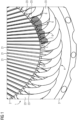
- FIG 1 shows an example of an enlarged section of a stator 1 of a rotary electrical machine in a perspective view, so that the inside but not the outside of the stator 1 can be seen.
- the electrical machine can be designed as a linear electrical machine in individual cases.
- the stator 1 has a laminated core 2 with a plurality of individual stator laminations.
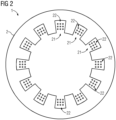
- FIG 2 shows a section through the laminated core 2.
- FIG 2 It is particularly evident that grooves 21 are provided in the laminated core 2 (on the inside of the stator).
- the laminated core 2 is manufactured in a conventional manner and therefore does not need to be explained in more detail.
- the grooves 21 can - as is generally customary - be introduced into the laminated core 2 by punching out the stator laminations accordingly.
- Windings 22 of a stator winding system are introduced into the slots 21.
- the windings 22 can form a multi-phase, for example a three-phase stator winding system.
- the windings 22 of the individual phases are usually introduced into the slots 21 sequentially one after the other.
- the windings 22 are introduced as such in a conventional manner and therefore do not need to be explained in more detail.
- the windings 22 can be designed as so-called random windings or as so-called laid windings, as required.
- the windings 22, e.g. round wires, enamelled wires can be formed, for example, as copper strands from a large number of copper wires.
- FIG 1 further shows that the stator 1 is fitted into a housing 3, e.g. made of aluminium.
- FIG 1 shows a winding head 4 of the stator 1.
- the other winding head is located on a FIG 1 shown end of the stator 1 and is not shown for the sake of simplicity.
- the winding head 4 is formed by free winding ends 23 that are not inserted into the slots 21.
- the winding ends 23 that protrude from the slots 21 in the longitudinal direction of the stator 1 are combined or tied together to form the winding head 4 at a distance 5 from a laminated core end 24 (a front side of the stator 1).
- the tying can be done, for example, with an adhesive tape or something similar.
- the formation of the winding head 4 from the winding ends 23 as such takes place in a conventional manner and therefore does not need to be explained in more detail.
- the distance 5 can, for example, be approximately 5 mm to 150 mm, depending on the size of the stator 1.
- the winding ends 23 run approximately parallel to one another and also approximately parallel to the longitudinal axis of the stator 1.
- FIG 1 It can also be seen that the windings 22 outside the laminated core 2 are spaced apart from one another in the circumferential direction of the stator 1 or the winding head 4, so that gaps 6 are formed between the windings 22.
- the gaps 6, preferably all gaps 6, are spanned or covered with a polymer layer 7.
- the polymer layer 7 preferably adheres to the winding ends 23 without any additional auxiliary/adhesive agents.
- the polymer layer 7 may have a thickness of about 0.1 mm to 3 mm, preferably between 0.5 mm and 1.5 mm, for example about 1.0 mm.
- FIG 3 shows an enlarged section of the FIG 1 .
- FIG 3 shows that an intermediate space 6 between the winding ends 23 is spanned or covered or covered with the polymer layer 7.
- the polymer layer can extend in the circumferential direction of the stator 1 at least between the two adjacent winding ends 23 and in the longitudinal direction of the stator 1 from the laminated core end 24 to the winding head 4 in order to cover the intermediate spaces in such a way that no flow of liquid medium, in particular of winding head casting compound, through the intermediate space 6 (i.e. from the outside of the stator to the inside of the stator or vice versa) is possible.
- the polymer layer 7 spans and thus closes the gap 6 and adheres to both winding ends 23 through which the gap 6 is formed.
- Liquid molding material with thermally conductive particles can be used as a winding head casting compound or simply as a casting compound.
- the molding material can be reactive resin, e.g. epoxy, polyurethane or polyester.
- the thermally conductive particles embedded as microparticles in the matrix can be, for example, quartz powder, fused silica, boron nitride or aluminum oxide particles. This list of materials is not complete.
- the polymer layer 7 preferably spans each gap 6.
- the polymer layer 7 extends in the longitudinal direction of the stator for about 5 mm to 150 mm depending on the size of the stator 1.
- the polymer layer 6 can fill the gaps on the inside of the stator (as in FIG 1 and FIG 3 shown) and/or outside the stator (not shown).
- the polymer layer can be designed as a band which has a width greater than or equal to ( ⁇ ) the distance 5.
- the band can be self-contained, so that it spans or covers an area on the inside and/or outside of the stator, which area is bordered by the gaps 6.
- the polymer layer 7 can thus be designed as a collar on the inside and/or outside of the stator.
- the polymer layer 7 does not protrude into the bore of the stator 1 provided for a rotor.
- the polymer layer 7 may comprise cured plastic adhesive, preferably consisting of the cured plastic adhesive.
- thermoplastic hot melt adhesive e.g. polyolefin or polyamide
- polyolefin or polyamide can be used.
- good results have been achieved with the materials 3M Scotch Weld 3731, 3789 and 3779 from 3M, whereby the first material is a polyolefin and the other two materials are polyamides.
- the plastic adhesive can be sprayed on in the form of threads, so that the threads form overlapping loops are spun onto one another and form a net structure that spans the gap 6 or the gaps 6.
- the threads can have a diameter of approximately 50-500pm.
- the polymer layer 7 can adhere to the winding ends 23 without any additional auxiliary/adhesive agents. This means in particular that no additional adhesive layer or the like is required for the polymer layer 7 to adhere to the winding ends 23 and make the gaps 6 and the inside or the bore of the stator 1 liquid-tight.
- the polymer layer 7 can also comprise RT (room temperature, approx. 25°C) curing adhesives or be formed from such.
- the plastic adhesive used can comprise fiber reinforcement.
- the polymer layer 7 can be formed by spraying on the plastic adhesive and can, for example, have the form of a spray wallpaper.
- the plastic adhesive can be chemically curing, for example duromer plastics can be used which are UV-curing, for example. Physically curing plastics can be used as plastic adhesives. Filled plastics (fibers, particles) can be used as plastic adhesives, provided they remain applicable, e.g. in the form of a spray wallpaper.
- Solvent-containing plastics can also be used as plastic adhesives, which solidify through evaporation of the solvent (e.g. hairspray, PVA).
- Reactive resins e.g. epoxy, PEI, PU
- plastic adhesives e.g. epoxy, PEI, PU
- a winding head opposite the winding head 4 can also have a polymer layer which can be arranged in the same way as the polymer layer 7 described above and spans the corresponding gaps in order to prevent flow of liquid medium into the stator bore provided for the rotor.
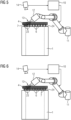
- FIG 4 clarifies the problems of the prior art mentioned in the introduction to the description.
- FIG 4 lets the stator 1 of the Figures 1 to 3 which is inserted into a housing 3. Between the winding ends 23, which run between the laminated core end 24 and the winding head 4, there are gaps 6.
- FIG 4 shows that when the winding head is cast with a casting compound 100, this flows through the gaps 6 into the stator bore if no additional tool is used.
- the additional tool can be, for example, a mandrel or a large plastic tube, which prevents the flow into the stator bore.
- the additional tool must always be sealed and depends on the diameter of the bore, i.e. is dependent on the motor size.
- the polymer layer 7 is neither dependent on the diameter of the bore nor on the machine size.
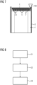
- Figures 5 to 7 show examples of various process steps of a fully automated winding head casting process, the flow chart of which is shown in FIG 8 is shown.
- FIG 5 shows the stator 1 with the winding head 4.
- the polymer layer 7 can be seen, which spans a single gap 6 between two winding ends 23.
- FIG 5 a device 10 which controls a robot arm 11 assigned to it.
- the robot arm 11 carries a nozzle 12 to which thermoplastic hot melt adhesive is supplied.
- the nozzle 12 can also contain a reservoir with thermoplastic hot melt adhesive.
- a thread 13 of the thermoplastic hot melt adhesive is produced by means of the nozzle 12.
- the nozzle 12 is moved in such a way that the thread 13 is applied to the gap 6, for example, by the movement of the nozzle 12 in order to span it, for example, in the form of a net structure - step S1 of the FIG 8 .
- the thread 13 can have a diameter in a range between 50 ⁇ m and 500 ⁇ m, for example.
- thermoplastic hot melt adhesive can be supplied to the nozzle 12 with a working pressure of between 1 bar and 10 bar and/or with a working temperature of between 180°C and 220°C.
- an adhesive based on a polyolefin with a melting temperature of approx. 200°C was used.
- the adhesive was sprayed on at a working temperature T of 220°C and a pressure p of 3 bar.
- the adhesive exited the nozzle 30 at a speed of approx. 5 m/s.
- the distance between the nozzle 14 and the respective flat area was approx. 8 cm, the speed of the nozzle 12 was 600 rpm.
- the loops 13 adhered very well to the winding ends 23 and led to a complete over-tensioning of the gaps 6 to be closed.
- This process step and also the other process steps described below can be recorded, for example, by an optical detection system 14, for example by a camera, e.g. by a 3D camera for the purpose of checking, for example quality control.
- the optical detection system 14 is assigned to the device 10.
- the device 10 can be set up to process and/or analyze what is recorded by the optical detection system 14 and, based on this, to adapt the control of the robot arm 11 accordingly.
- the recorded location and the recorded course of the gaps 6 can be fed to a device 10.
- the device 10 can therefore be able to take the recorded location and the recorded course of the gaps 6 to be sprayed into account accordingly when moving the nozzle 12.
- FIG 6 shows a further process step in which the thread 13 is spun layer by layer and over the entire surface - step S2 of the FIG 8
- the nozzle 12 is moved in such a way that the polymer layer 7 spans several, preferably all, gaps 6.
- the polymer layer 7 remains adhered to the winding ends 23 on the inside of the stator.
- polymer layer 7 can also be applied to the outside of the stator (not shown here).
- FIG 7 shows a process step in which the stator 1 is inserted into the housing 3 and its winding head 4 is cast with a casting compound 100 - step S3 of the FIG 8 . Due to the polymer layer 7, the potting compound 100 does not penetrate into the bore of the stator 1 intended for the rotor.
- the potting compound 100 is a better heat conductor than air and thermally bonds the winding head 4 to the housing 3. This significantly reduces the number of hotspots that arise in the winding head during operation.
- the polymer layer 7 can be at least partially peeled off after the potting compound 100 has cured.
- the stator 1, which is completely encapsulated with the housing 3, can then be used in an electrical, preferably rotary machine.
- An electrical, preferably rotary machine with the stator 1 encapsulated with the housing 3 is thus part of the present disclosure.
- stator and the methods described here enable enclosure by e.g. to save an inner mandrel as a casting tool, which is very complex in conventional casting processes because it is variance-dependent.
- the polymer layer is variance-independent and can be applied fully automatically.
- the polymer layer can be at least partially or almost completely recycled.
- the winding head casting is therefore no longer a complex, largely manual process, but can be carried out completely automatically.
Landscapes
- Engineering & Computer Science (AREA)
- Power Engineering (AREA)
- Manufacturing & Machinery (AREA)
- Manufacture Of Motors, Generators (AREA)
Claims (8)
- Procédé de coulée d'une tête (4) de bobine d'un stator (1), dans lequel- on se procure un stator (1), qui a un paquet (2) de tôles ayant des encoches (21) et une tête (4) de bobine, dans lequel on introduit des enroulements (22) dans les encoches (21), dans lequel la tête (4) de bobine est formée à partir des extrémités (23) d'enroulement sortant des encoches (21) et à une distance (5) d'une extrémité (24) du paquet de tôles, dans lequel les extrémités (23) d'enroulement s'étendent dans une partie comprise entre l'extrémité (24) du paquet de tôles et la tête (4) de bobine, de manière à créer dans cette partie des espaces (6) intermédiaires entre les extrémités (23) de bobine,- on adapte le stator (1) dans une carcasse (3) d'une machine électrique et on coule la tête (4) de bobine du stator (1) avec une composition de coulée,
caractérisé en ce que- on recouvre, avant la coulée, au moins des espaces (6) intermédiaires d'une couche (7) de polymère, de manière à empêcher la composition (100) de coulée de passer dans le au moins un espace (6) intermédiaire recouvert. - Procédé suivant la revendication 1, dans lequel on élimine au moins en partie la couche (7) de polymère, après la coulée et le durcissement de la composition de coulée.
- Procédé suivant la revendication 1 ou 2, dans lequel on produit, au moyen d'une buse (12), la couche (7) de polymère par projection et/ou centrifugation et/ou pulvérisation d'un milieu contenant de la colle.
- Procédé suivant l'une des revendications 1 à 3, dans lequel, pendant la production, on déplace la buse (12), de manière à déposer, couche par couche et en recouvrant la surface, le milieu contenant de la colle par le mouvement de déplacement de la buse (12), de manière à ce que le milieu contenant de la colle recouvre le au moins un des espaces (6) intermédiaires.
- Procédé suivant l'une des revendications 1 à 4, dans lequel, au moyen d'une buse (12), on produit un fil (13) d'une colle fusible thermoplastique, dans lequel, pendant la production, on déplace la buse (12), de manière à déposer le fil (13) par le mouvement de déplacement de la buse (12), de manière à centrifuger le fil sous la forme de boucles, qui se chevauchent afin de former une structure en réseau, dans laquelle la structure en réseau recouvre le au moins un des espaces (6) intermédiaires.
- Procédé suivant l'une des revendications 1 à 5, dans lequel on recouvre tous les espaces (6) intermédiaires d'une couche (7) de polymère.
- Procédé suivant l'une des revendications 1 à 6, dans lequel on met la couche (7) de polymère du côté intérieur du stator et/ou du côté extérieur du stator.
- Procédé suivant l'une des revendications 1 à 7, dans lequel le dépôt de la colle fusible thermoplastique s'effectue d'une manière entièrement automatique, en particulier par un robot (11).
Applications Claiming Priority (2)
| Application Number | Priority Date | Filing Date | Title |
|---|---|---|---|
| EP21166276.2A EP4068577A1 (fr) | 2021-03-31 | 2021-03-31 | Stator pour une machine tournante électrique |
| PCT/EP2022/057863 WO2022207475A1 (fr) | 2021-03-31 | 2022-03-25 | Stator pour une machine tournante électrique |
Publications (2)
| Publication Number | Publication Date |
|---|---|
| EP4248552A1 EP4248552A1 (fr) | 2023-09-27 |
| EP4248552B1 true EP4248552B1 (fr) | 2024-08-28 |
Family
ID=75339530
Family Applications (2)
| Application Number | Title | Priority Date | Filing Date |
|---|---|---|---|
| EP21166276.2A Withdrawn EP4068577A1 (fr) | 2021-03-31 | 2021-03-31 | Stator pour une machine tournante électrique |
| EP22717619.5A Active EP4248552B1 (fr) | 2021-03-31 | 2022-03-25 | Stator pour une machine tournante électrique |
Family Applications Before (1)
| Application Number | Title | Priority Date | Filing Date |
|---|---|---|---|
| EP21166276.2A Withdrawn EP4068577A1 (fr) | 2021-03-31 | 2021-03-31 | Stator pour une machine tournante électrique |
Country Status (4)
| Country | Link |
|---|---|
| US (1) | US12021420B2 (fr) |
| EP (2) | EP4068577A1 (fr) |
| CN (1) | CN117099288A (fr) |
| WO (1) | WO2022207475A1 (fr) |
Families Citing this family (2)
| Publication number | Priority date | Publication date | Assignee | Title |
|---|---|---|---|---|
| DE102022212976A1 (de) * | 2022-12-01 | 2024-06-06 | Robert Bosch Gesellschaft mit beschränkter Haftung | Statoranordnung und Verfahren zum Herstellen einer Statoranordnung |
| EP4693835A1 (fr) * | 2024-08-05 | 2026-02-11 | Innomotics GmbH | Procédé de fabrication d'une protection de tête de bobine d'un stator par revêtement de rainure |
Family Cites Families (4)
| Publication number | Priority date | Publication date | Assignee | Title |
|---|---|---|---|---|
| DE3133734C2 (de) * | 1981-08-26 | 1985-04-25 | Loher Gmbh, 8399 Ruhstorf | Verfahren zum Überziehen bzw. Vergießen von Wickelköpfen elektrischer Vorrichtungen sowie Anwendung zum Tränken |
| DE10324680A1 (de) * | 2003-05-30 | 2004-12-23 | Siemens Ag | Elektrische Maschine mit druckfest gekapseltem Stator |
| DE102005017113B4 (de) * | 2005-04-13 | 2007-04-12 | Siemens Ag | Schutzschichtanordnung für einen Wickelkopf einer elektrischen Maschine |
| EP3772158B1 (fr) * | 2019-08-02 | 2021-09-29 | Siemens Aktiengesellschaft | Isolation des extrémités d'enroulement d'un enroulement de stator |
-
2021
- 2021-03-31 EP EP21166276.2A patent/EP4068577A1/fr not_active Withdrawn
-
2022
- 2022-03-25 EP EP22717619.5A patent/EP4248552B1/fr active Active
- 2022-03-25 WO PCT/EP2022/057863 patent/WO2022207475A1/fr not_active Ceased
- 2022-03-25 US US18/284,176 patent/US12021420B2/en active Active
- 2022-03-25 CN CN202280026566.4A patent/CN117099288A/zh active Pending
Also Published As
| Publication number | Publication date |
|---|---|
| US12021420B2 (en) | 2024-06-25 |
| CN117099288A (zh) | 2023-11-21 |
| US20240088763A1 (en) | 2024-03-14 |
| EP4248552A1 (fr) | 2023-09-27 |
| EP4068577A1 (fr) | 2022-10-05 |
| WO2022207475A1 (fr) | 2022-10-06 |
Similar Documents
| Publication | Publication Date | Title |
|---|---|---|
| EP1153726B1 (fr) | Isolation d'enroulements de stator par moulage par injection | |
| DE102019111729A1 (de) | Vorrichtung zum kühlen eines elektromotors und verfahren zur herstellung desselben | |
| EP4248552B1 (fr) | Stator pour une machine tournante électrique | |
| WO2014117773A2 (fr) | Machine électrique munie d'un dispositif de refroidissement et procédé de fabrication de ladite machine | |
| EP1573882B1 (fr) | Bobines pour moteurs electriques realisees selon la technique des conducteurs multibrins | |
| DE102020101035A1 (de) | Elektromotor mit verbesserter wärmeableitung und produktivität und verfahren zur herstellung desselben | |
| WO1991019347A1 (fr) | Procede pour la fabrication du stator d'une machine electrique, de preference d'un alternateur triphase | |
| DE10023204A1 (de) | Isolierung von Statorwicklungen durch Schrumpfschläuche | |
| WO2023217471A1 (fr) | Rotor pour machine de traction électrique d'un véhicule automobile et machine de traction électrique | |
| DE102007006513A1 (de) | Statoranordnung und Herstellungsverfahren | |
| WO2016050528A1 (fr) | Pièce active faisant office de rotor ou de stator, procédé de production d'une pièce active de ce type et moteur électrique | |
| WO2023117716A1 (fr) | Procédé de production d'un rotor pour une machine électrique, et machine électrique | |
| EP1154542A1 (fr) | Méthode d'Isolation des bobines | |
| WO2015071091A2 (fr) | Machine électrique à tête de bobine surmoulée | |
| EP1573883B1 (fr) | Element d'isolement elastique extrude de conducteurs de machines electriques | |
| DE19860412A1 (de) | Innenglimmschutz für Statorleiter in Motoren und Generatoren | |
| EP4068596A1 (fr) | Procédé de fabrication d'un stator d'une machine dynamoélectrique | |
| EP1742335B1 (fr) | Stator et procédé de fabrication d'un stator d'un moteur électrique | |
| EP2975736B1 (fr) | Stator d'une machine électrique rotative et sa fabrication | |
| DE2912684C2 (de) | Von Kraftstoff durchströmter Elektromotor in einem Kraftstoff-Förderaggregat | |
| DE212021000371U1 (de) | Statorbaugruppe für eine elektrische Maschine, elektrische Maschine und Elektrowerkzeug | |
| DE102021214589A1 (de) | Statoranordnung, elektrische Maschine mit einer solchen Statoranordnung sowie Verfahren zur Herstellung einer Statoranordnung | |
| EP1753113B1 (fr) | Enrobage de stator | |
| WO2017036745A1 (fr) | Machine électrique et procédé de fonctionnement d'une machine électrique de ce type ainsi que procédé de fabrication | |
| WO2023227339A1 (fr) | Procédé de production d'un stator d'une machine dynamoélectrique |
Legal Events
| Date | Code | Title | Description |
|---|---|---|---|
| STAA | Information on the status of an ep patent application or granted ep patent |
Free format text: STATUS: UNKNOWN |
|
| STAA | Information on the status of an ep patent application or granted ep patent |
Free format text: STATUS: THE INTERNATIONAL PUBLICATION HAS BEEN MADE |
|
| PUAI | Public reference made under article 153(3) epc to a published international application that has entered the european phase |
Free format text: ORIGINAL CODE: 0009012 |
|
| STAA | Information on the status of an ep patent application or granted ep patent |
Free format text: STATUS: REQUEST FOR EXAMINATION WAS MADE |
|
| 17P | Request for examination filed |
Effective date: 20230622 |
|
| AK | Designated contracting states |
Kind code of ref document: A1 Designated state(s): AL AT BE BG CH CY CZ DE DK EE ES FI FR GB GR HR HU IE IS IT LI LT LU LV MC MK MT NL NO PL PT RO RS SE SI SK SM TR |
|
| GRAP | Despatch of communication of intention to grant a patent |
Free format text: ORIGINAL CODE: EPIDOSNIGR1 |
|
| STAA | Information on the status of an ep patent application or granted ep patent |
Free format text: STATUS: GRANT OF PATENT IS INTENDED |
|
| DAV | Request for validation of the european patent (deleted) | ||
| DAX | Request for extension of the european patent (deleted) | ||
| INTG | Intention to grant announced |
Effective date: 20240405 |
|
| RAP1 | Party data changed (applicant data changed or rights of an application transferred) |
Owner name: INNOMOTICS GMBH |
|
| GRAS | Grant fee paid |
Free format text: ORIGINAL CODE: EPIDOSNIGR3 |
|
| GRAA | (expected) grant |
Free format text: ORIGINAL CODE: 0009210 |
|
| STAA | Information on the status of an ep patent application or granted ep patent |
Free format text: STATUS: THE PATENT HAS BEEN GRANTED |
|
| AK | Designated contracting states |
Kind code of ref document: B1 Designated state(s): AL AT BE BG CH CY CZ DE DK EE ES FI FR GB GR HR HU IE IS IT LI LT LU LV MC MK MT NL NO PL PT RO RS SE SI SK SM TR |
|
| REG | Reference to a national code |
Ref country code: CH Ref legal event code: EP |
|
| REG | Reference to a national code |
Ref country code: DE Ref legal event code: R081 Ref document number: 502022001579 Country of ref document: DE Owner name: INNOMOTICS GMBH, DE Free format text: FORMER OWNER: INNOMOTICS GMBH, MUENCHEN, DE Ref country code: DE Ref legal event code: R081 Ref document number: 502022001579 Country of ref document: DE Owner name: ANMELDERANGABEN UNKLAR / UNVOLLSTAENDIG, DE Free format text: FORMER OWNER: INNOMOTICS GMBH, MUENCHEN, DE |
|
| REG | Reference to a national code |
Ref country code: DE Ref legal event code: R096 Ref document number: 502022001579 Country of ref document: DE |
|
| REG | Reference to a national code |
Ref country code: IE Ref legal event code: FG4D Free format text: LANGUAGE OF EP DOCUMENT: GERMAN |
|
| REG | Reference to a national code |
Ref country code: LT Ref legal event code: MG9D |
|
| PG25 | Lapsed in a contracting state [announced via postgrant information from national office to epo] |
Ref country code: NO Free format text: LAPSE BECAUSE OF FAILURE TO SUBMIT A TRANSLATION OF THE DESCRIPTION OR TO PAY THE FEE WITHIN THE PRESCRIBED TIME-LIMIT Effective date: 20241128 |
|
| PG25 | Lapsed in a contracting state [announced via postgrant information from national office to epo] |
Ref country code: PL Free format text: LAPSE BECAUSE OF FAILURE TO SUBMIT A TRANSLATION OF THE DESCRIPTION OR TO PAY THE FEE WITHIN THE PRESCRIBED TIME-LIMIT Effective date: 20240828 Ref country code: NL Free format text: LAPSE BECAUSE OF FAILURE TO SUBMIT A TRANSLATION OF THE DESCRIPTION OR TO PAY THE FEE WITHIN THE PRESCRIBED TIME-LIMIT Effective date: 20240828 Ref country code: GR Free format text: LAPSE BECAUSE OF FAILURE TO SUBMIT A TRANSLATION OF THE DESCRIPTION OR TO PAY THE FEE WITHIN THE PRESCRIBED TIME-LIMIT Effective date: 20241129 Ref country code: FI Free format text: LAPSE BECAUSE OF FAILURE TO SUBMIT A TRANSLATION OF THE DESCRIPTION OR TO PAY THE FEE WITHIN THE PRESCRIBED TIME-LIMIT Effective date: 20240828 Ref country code: PT Free format text: LAPSE BECAUSE OF FAILURE TO SUBMIT A TRANSLATION OF THE DESCRIPTION OR TO PAY THE FEE WITHIN THE PRESCRIBED TIME-LIMIT Effective date: 20241230 |
|
| PG25 | Lapsed in a contracting state [announced via postgrant information from national office to epo] |
Ref country code: BG Free format text: LAPSE BECAUSE OF FAILURE TO SUBMIT A TRANSLATION OF THE DESCRIPTION OR TO PAY THE FEE WITHIN THE PRESCRIBED TIME-LIMIT Effective date: 20240828 |
|
| PG25 | Lapsed in a contracting state [announced via postgrant information from national office to epo] |
Ref country code: LV Free format text: LAPSE BECAUSE OF FAILURE TO SUBMIT A TRANSLATION OF THE DESCRIPTION OR TO PAY THE FEE WITHIN THE PRESCRIBED TIME-LIMIT Effective date: 20240828 |
|
| REG | Reference to a national code |
Ref country code: NL Ref legal event code: MP Effective date: 20240828 |
|
| PG25 | Lapsed in a contracting state [announced via postgrant information from national office to epo] |
Ref country code: IS Free format text: LAPSE BECAUSE OF FAILURE TO SUBMIT A TRANSLATION OF THE DESCRIPTION OR TO PAY THE FEE WITHIN THE PRESCRIBED TIME-LIMIT Effective date: 20241228 |
|
| PG25 | Lapsed in a contracting state [announced via postgrant information from national office to epo] |
Ref country code: HR Free format text: LAPSE BECAUSE OF FAILURE TO SUBMIT A TRANSLATION OF THE DESCRIPTION OR TO PAY THE FEE WITHIN THE PRESCRIBED TIME-LIMIT Effective date: 20240828 |
|
| PG25 | Lapsed in a contracting state [announced via postgrant information from national office to epo] |
Ref country code: RS Free format text: LAPSE BECAUSE OF FAILURE TO SUBMIT A TRANSLATION OF THE DESCRIPTION OR TO PAY THE FEE WITHIN THE PRESCRIBED TIME-LIMIT Effective date: 20241128 Ref country code: ES Free format text: LAPSE BECAUSE OF FAILURE TO SUBMIT A TRANSLATION OF THE DESCRIPTION OR TO PAY THE FEE WITHIN THE PRESCRIBED TIME-LIMIT Effective date: 20240828 |
|
| PG25 | Lapsed in a contracting state [announced via postgrant information from national office to epo] |
Ref country code: RS Free format text: LAPSE BECAUSE OF FAILURE TO SUBMIT A TRANSLATION OF THE DESCRIPTION OR TO PAY THE FEE WITHIN THE PRESCRIBED TIME-LIMIT Effective date: 20241128 Ref country code: PT Free format text: LAPSE BECAUSE OF FAILURE TO SUBMIT A TRANSLATION OF THE DESCRIPTION OR TO PAY THE FEE WITHIN THE PRESCRIBED TIME-LIMIT Effective date: 20241230 Ref country code: PL Free format text: LAPSE BECAUSE OF FAILURE TO SUBMIT A TRANSLATION OF THE DESCRIPTION OR TO PAY THE FEE WITHIN THE PRESCRIBED TIME-LIMIT Effective date: 20240828 Ref country code: NO Free format text: LAPSE BECAUSE OF FAILURE TO SUBMIT A TRANSLATION OF THE DESCRIPTION OR TO PAY THE FEE WITHIN THE PRESCRIBED TIME-LIMIT Effective date: 20241128 Ref country code: NL Free format text: LAPSE BECAUSE OF FAILURE TO SUBMIT A TRANSLATION OF THE DESCRIPTION OR TO PAY THE FEE WITHIN THE PRESCRIBED TIME-LIMIT Effective date: 20240828 Ref country code: LV Free format text: LAPSE BECAUSE OF FAILURE TO SUBMIT A TRANSLATION OF THE DESCRIPTION OR TO PAY THE FEE WITHIN THE PRESCRIBED TIME-LIMIT Effective date: 20240828 Ref country code: IS Free format text: LAPSE BECAUSE OF FAILURE TO SUBMIT A TRANSLATION OF THE DESCRIPTION OR TO PAY THE FEE WITHIN THE PRESCRIBED TIME-LIMIT Effective date: 20241228 Ref country code: HR Free format text: LAPSE BECAUSE OF FAILURE TO SUBMIT A TRANSLATION OF THE DESCRIPTION OR TO PAY THE FEE WITHIN THE PRESCRIBED TIME-LIMIT Effective date: 20240828 Ref country code: GR Free format text: LAPSE BECAUSE OF FAILURE TO SUBMIT A TRANSLATION OF THE DESCRIPTION OR TO PAY THE FEE WITHIN THE PRESCRIBED TIME-LIMIT Effective date: 20241129 Ref country code: FI Free format text: LAPSE BECAUSE OF FAILURE TO SUBMIT A TRANSLATION OF THE DESCRIPTION OR TO PAY THE FEE WITHIN THE PRESCRIBED TIME-LIMIT Effective date: 20240828 Ref country code: ES Free format text: LAPSE BECAUSE OF FAILURE TO SUBMIT A TRANSLATION OF THE DESCRIPTION OR TO PAY THE FEE WITHIN THE PRESCRIBED TIME-LIMIT Effective date: 20240828 Ref country code: BG Free format text: LAPSE BECAUSE OF FAILURE TO SUBMIT A TRANSLATION OF THE DESCRIPTION OR TO PAY THE FEE WITHIN THE PRESCRIBED TIME-LIMIT Effective date: 20240828 |
|
| REG | Reference to a national code |
Ref country code: DE Ref legal event code: R081 Ref document number: 502022001579 Country of ref document: DE Owner name: INNOMOTICS GMBH, DE Free format text: FORMER OWNER: ANMELDERANGABEN UNKLAR / UNVOLLSTAENDIG, 80297 MUENCHEN, DE |
|
| PG25 | Lapsed in a contracting state [announced via postgrant information from national office to epo] |
Ref country code: SM Free format text: LAPSE BECAUSE OF FAILURE TO SUBMIT A TRANSLATION OF THE DESCRIPTION OR TO PAY THE FEE WITHIN THE PRESCRIBED TIME-LIMIT Effective date: 20240828 Ref country code: RO Free format text: LAPSE BECAUSE OF FAILURE TO SUBMIT A TRANSLATION OF THE DESCRIPTION OR TO PAY THE FEE WITHIN THE PRESCRIBED TIME-LIMIT Effective date: 20240828 Ref country code: DK Free format text: LAPSE BECAUSE OF FAILURE TO SUBMIT A TRANSLATION OF THE DESCRIPTION OR TO PAY THE FEE WITHIN THE PRESCRIBED TIME-LIMIT Effective date: 20240828 |
|
| PG25 | Lapsed in a contracting state [announced via postgrant information from national office to epo] |
Ref country code: EE Free format text: LAPSE BECAUSE OF FAILURE TO SUBMIT A TRANSLATION OF THE DESCRIPTION OR TO PAY THE FEE WITHIN THE PRESCRIBED TIME-LIMIT Effective date: 20240828 |
|
| PG25 | Lapsed in a contracting state [announced via postgrant information from national office to epo] |
Ref country code: CZ Free format text: LAPSE BECAUSE OF FAILURE TO SUBMIT A TRANSLATION OF THE DESCRIPTION OR TO PAY THE FEE WITHIN THE PRESCRIBED TIME-LIMIT Effective date: 20240828 |
|
| PG25 | Lapsed in a contracting state [announced via postgrant information from national office to epo] |
Ref country code: SK Free format text: LAPSE BECAUSE OF FAILURE TO SUBMIT A TRANSLATION OF THE DESCRIPTION OR TO PAY THE FEE WITHIN THE PRESCRIBED TIME-LIMIT Effective date: 20240828 |
|
| REG | Reference to a national code |
Ref country code: DE Ref legal event code: R097 Ref document number: 502022001579 Country of ref document: DE |
|
| PLBE | No opposition filed within time limit |
Free format text: ORIGINAL CODE: 0009261 |
|
| STAA | Information on the status of an ep patent application or granted ep patent |
Free format text: STATUS: NO OPPOSITION FILED WITHIN TIME LIMIT |
|
| 26N | No opposition filed |
Effective date: 20250530 |
|
| PG25 | Lapsed in a contracting state [announced via postgrant information from national office to epo] |
Ref country code: SE Free format text: LAPSE BECAUSE OF FAILURE TO SUBMIT A TRANSLATION OF THE DESCRIPTION OR TO PAY THE FEE WITHIN THE PRESCRIBED TIME-LIMIT Effective date: 20240828 |
|
| PG25 | Lapsed in a contracting state [announced via postgrant information from national office to epo] |
Ref country code: MC Free format text: LAPSE BECAUSE OF FAILURE TO SUBMIT A TRANSLATION OF THE DESCRIPTION OR TO PAY THE FEE WITHIN THE PRESCRIBED TIME-LIMIT Effective date: 20240828 |
|
| REG | Reference to a national code |
Ref country code: CH Ref legal event code: H13 Free format text: ST27 STATUS EVENT CODE: U-0-0-H10-H13 (AS PROVIDED BY THE NATIONAL OFFICE) Effective date: 20251023 |
|
| PG25 | Lapsed in a contracting state [announced via postgrant information from national office to epo] |
Ref country code: LU Free format text: LAPSE BECAUSE OF NON-PAYMENT OF DUE FEES Effective date: 20250325 |
|
| REG | Reference to a national code |
Ref country code: BE Ref legal event code: MM Effective date: 20250331 |
|
| PG25 | Lapsed in a contracting state [announced via postgrant information from national office to epo] |
Ref country code: FR Free format text: LAPSE BECAUSE OF NON-PAYMENT OF DUE FEES Effective date: 20250331 |
|
| PG25 | Lapsed in a contracting state [announced via postgrant information from national office to epo] |
Ref country code: BE Free format text: LAPSE BECAUSE OF NON-PAYMENT OF DUE FEES Effective date: 20250331 |
|
| PG25 | Lapsed in a contracting state [announced via postgrant information from national office to epo] |
Ref country code: CH Free format text: LAPSE BECAUSE OF NON-PAYMENT OF DUE FEES Effective date: 20250331 |
|
| PG25 | Lapsed in a contracting state [announced via postgrant information from national office to epo] |
Ref country code: IE Free format text: LAPSE BECAUSE OF NON-PAYMENT OF DUE FEES Effective date: 20250325 |
|
| PGFP | Annual fee paid to national office [announced via postgrant information from national office to epo] |
Ref country code: DE Payment date: 20260325 Year of fee payment: 5 |
|
| PGFP | Annual fee paid to national office [announced via postgrant information from national office to epo] |
Ref country code: AT Payment date: 20260301 Year of fee payment: 5 |
|
| PGFP | Annual fee paid to national office [announced via postgrant information from national office to epo] |
Ref country code: IT Payment date: 20260324 Year of fee payment: 5 |