EP4248552B1 - Stator für eine elektrische rotatorische maschine - Google Patents
Stator für eine elektrische rotatorische maschine Download PDFInfo
- Publication number
- EP4248552B1 EP4248552B1 EP22717619.5A EP22717619A EP4248552B1 EP 4248552 B1 EP4248552 B1 EP 4248552B1 EP 22717619 A EP22717619 A EP 22717619A EP 4248552 B1 EP4248552 B1 EP 4248552B1
- Authority
- EP
- European Patent Office
- Prior art keywords
- stator
- polymer layer
- winding
- nozzle
- adhesive
- Prior art date
- Legal status (The legal status is an assumption and is not a legal conclusion. Google has not performed a legal analysis and makes no representation as to the accuracy of the status listed.)
- Active
Links
Images

Classifications
-
- H—ELECTRICITY
- H02—GENERATION; CONVERSION OR DISTRIBUTION OF ELECTRIC POWER
- H02K—DYNAMO-ELECTRIC MACHINES
- H02K15/00—Processes or apparatus specially adapted for manufacturing, assembling, maintaining or repairing of dynamo-electric machines
- H02K15/10—Applying solid insulation to windings, stators or rotors, e.g. applying insulating tapes
- H02K15/105—Applying solid insulation to windings, stators or rotors, e.g. applying insulating tapes to the windings
-
- H—ELECTRICITY
- H02—GENERATION; CONVERSION OR DISTRIBUTION OF ELECTRIC POWER
- H02K—DYNAMO-ELECTRIC MACHINES
- H02K15/00—Processes or apparatus specially adapted for manufacturing, assembling, maintaining or repairing of dynamo-electric machines
- H02K15/12—Impregnating, moulding insulation, heating or drying of windings, stators, rotors or machines
-
- H—ELECTRICITY
- H02—GENERATION; CONVERSION OR DISTRIBUTION OF ELECTRIC POWER
- H02K—DYNAMO-ELECTRIC MACHINES
- H02K3/00—Details of windings
- H02K3/32—Windings characterised by the shape, form or construction of the insulation
- H02K3/38—Windings characterised by the shape, form or construction of the insulation around winding heads, equalising connectors, or connections thereto
-
- B—PERFORMING OPERATIONS; TRANSPORTING
- B29—WORKING OF PLASTICS; WORKING OF SUBSTANCES IN A PLASTIC STATE IN GENERAL
- B29K—INDEXING SCHEME ASSOCIATED WITH SUBCLASSES B29B, B29C OR B29D, RELATING TO MOULDING MATERIALS OR TO MATERIALS FOR MOULDS, REINFORCEMENTS, FILLERS OR PREFORMED PARTS, e.g. INSERTS
- B29K2105/00—Condition, form or state of moulded material or of the material to be shaped
- B29K2105/06—Condition, form or state of moulded material or of the material to be shaped containing reinforcements, fillers or inserts
- B29K2105/12—Condition, form or state of moulded material or of the material to be shaped containing reinforcements, fillers or inserts of short lengths, e.g. chopped filaments, staple fibres or bristles
-
- B—PERFORMING OPERATIONS; TRANSPORTING
- B29—WORKING OF PLASTICS; WORKING OF SUBSTANCES IN A PLASTIC STATE IN GENERAL
- B29L—INDEXING SCHEME ASSOCIATED WITH SUBCLASS B29C, RELATING TO PARTICULAR ARTICLES
- B29L2031/00—Other particular articles
- B29L2031/08—Blades for rotors, stators, fans, turbines or the like, e.g. screw propellers
-
- H—ELECTRICITY
- H02—GENERATION; CONVERSION OR DISTRIBUTION OF ELECTRIC POWER
- H02K—DYNAMO-ELECTRIC MACHINES
- H02K9/00—Arrangements for cooling or ventilating
- H02K9/22—Arrangements for cooling or ventilating by solid heat conducting material embedded in, or arranged in contact with, the stator or rotor, e.g. heat bridges
- H02K9/223—Heat bridges
Definitions
- the invention relates to a method for casting a winding head of a stator of an electrical machine, wherein the stator has a laminated core with slots and a winding head, wherein windings are introduced into the slots, wherein the winding head is formed from winding ends emerging from the slots and has a distance from a laminated core end, wherein the winding ends run in a region between the laminated core end and the winding head in such a way that gaps are formed in this region between the (individual) winding ends.
- the electrical rotary machine is preferably a motor.
- the stators and the winding head casting processes of the type mentioned above are well known from the state of the art.
- Low-voltage motors in the power classes 0.5 kW to 2000 kW are impregnated using cold dipping processes or hot dipping processes (e.g. current UV process) for cost reasons.
- the stators are dipped into a tank of liquid resin and then thermally hardened.
- the geometric gaps in the copper winding are largely filled with resin and thus solidified, electrically insulated and thermally connected to the laminated core.
- the winding heads i.e. the necessary copper strands that connect the active areas in the slots.
- the winding heads are again equipped with surface insulating materials (e.g.
- the thermal connection of the winding heads to the aluminum housing is only provided via an air space/air gap that is filled with flowing (convective) air.
- the cooling of the winding head is therefore very poor via the thermal contact transitions from the winding to the air and further from the air to the aluminum housing. This is to be seen as a critical and limiting factor in the motor's performance class, as so-called hotspots are created in the winding head in particular, i.e.
- impellers can be provided inside the motors, e.g. low-voltage motors, to dissipate heat.
- the impellers are mounted directly on the shaft and drive air convection in proportion to the speed of the motor, so that the housing or its cooling fins are surrounded by convective air from the outside.
- this ventilation has a negative effect on the performance or efficiency of the motors and is complex/cost-intensive in terms of production and product technology.
- the The winding head is not actively cooled here, as only the heat can be dissipated by the housing.
- the winding head must be thermally connected to the aluminum housing using a so-called winding head casting.
- This is a molding material filled with thermally conductive particles (reactive resin, e.g. epoxy, polyurethane or polyester).
- thermally conductive particles reactive resin, e.g. epoxy, polyurethane or polyester.
- the filler particles are dispersed in an optimized grain size distribution as microparticles in the matrix (reactive resin), so that the molding compound is as thin and flowable as possible.
- the filler content in the matrix is between 20 and 70 vol.%, depending on the desired flowability at processing temperature - i.e. process-dependent.
- the process costs of winding head casting are much more significant, as the impregnated stators have to be removed from the standard production flow and prepared for winding head casting using casting molds (first one side, then the other).
- a type of internal mandrel is inserted into the bore of the stator in a form-fitting manner to prevent the internal bore from being wetted with the casting compound.
- the stator is then heated to a higher temperature if necessary (e.g. 80°C to improve the flowability of the casting compound).
- the casting compound is then poured into the winding head reservoir thus encased.
- the compound is then hardened for several hours at approx. 150°C, e.g. in a hot air oven.
- the other winding head side is cast in the same way.
- the casting body thus encloses both winding heads both radially inside and radially outside, whereas the heat flow in the closed motor occurs largely radially outwards towards the aluminum housing.
- the complete Enclosure is rather a process-related phenomenon, since the inner mandrel serves as the housing wall and must then be removed and cleaned.
- the winding head casting is a very complex process (time, energy and material costs), which also brings more material into the motor than is actually necessary for the desired property (heat dissipation of the winding head towards the housing, radially outwards).
- a protective layer arrangement for a winding head of an electrical machine has a first and a second cover layer.
- the first and second cover layers enclose an electrical conductor arrangement of the winding head.
- the first cover layer consists of a gel-like and self-healing polymer material across the entire application temperature range.
- the second cover layer directly surrounds the first cover layer. It consists of a harder material than the first cover layer.
- the object of the present invention can therefore be seen in providing a winding head casting method which can be simplified in a cost-saving manner.
- the object is achieved according to the invention with a method mentioned at the outset according to independent claim 1 in that at least one of the intermediate spaces is spanned with a polymer layer in such a way that a flow of liquid medium through the at least one spanned intermediate space is prevented.
- This provides a method in which winding head potting can be carried out without additional tools.
- the polymer layer is applied on the inside and/or outside of the stator.
- the plastic adhesive is sprayed on in the form of threads, so that the threads are spun onto one another in the form of overlapping loops and form a net structure, wherein the net structure spans at least one of the intermediate spaces.
- the object is also achieved according to the invention with a method for producing a stator mentioned at the outset in that at least one of the intermediate spaces is covered with a polymer layer in such a way that a flow of liquid medium through the at least one covered intermediate space is prevented.
- the polymer layer is produced by spraying and/or spinning and/or spraying an adhesive-containing medium by means of a nozzle.
- the nozzle is moved during production in such a way that the adhesive-containing medium is applied in layers and over the entire surface by the movement of the nozzle in such a way that the adhesive-containing medium spans the at least one intermediate space.
- the adhesive-containing medium may comprise a thermoplastic hot melt adhesive.
- a thread of a thermoplastic hot melt adhesive is produced by means of a nozzle, during production the nozzle is moved in such a way that the thread is applied by the movement of the nozzle in such a way that the thread is spun in the form of overlapping loops and/or loops in order to form a network structure, wherein the network structure spans at least one of the intermediate spaces.
- the polymer layer is applied on the inside and/or outside of the stator.
- stator When the polymer layer is applied inside the stator, the stator can already be encased in the housing.
- thermoplastic hot melt adhesive takes place fully automatically, in particular with a robot.
- the polymer layer is at least partially removed after the casting and curing of the casting compound.
- both winding heads of the stator are provided with a polymer layer as described above and preferably encapsulated.
- identical or identically acting elements can each be provided with the same reference symbols.
- the reference symbols are provided only to simplify the identification of the elements provided with the reference symbols and have no limiting effect on the subject matter protected.
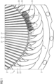
- FIG 1 shows an example of an enlarged section of a stator 1 of a rotary electrical machine in a perspective view, so that the inside but not the outside of the stator 1 can be seen.
- the electrical machine can be designed as a linear electrical machine in individual cases.
- the stator 1 has a laminated core 2 with a plurality of individual stator laminations.
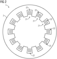
- FIG 2 shows a section through the laminated core 2.
- FIG 2 It is particularly evident that grooves 21 are provided in the laminated core 2 (on the inside of the stator).
- the laminated core 2 is manufactured in a conventional manner and therefore does not need to be explained in more detail.
- the grooves 21 can - as is generally customary - be introduced into the laminated core 2 by punching out the stator laminations accordingly.
- Windings 22 of a stator winding system are introduced into the slots 21.
- the windings 22 can form a multi-phase, for example a three-phase stator winding system.
- the windings 22 of the individual phases are usually introduced into the slots 21 sequentially one after the other.
- the windings 22 are introduced as such in a conventional manner and therefore do not need to be explained in more detail.
- the windings 22 can be designed as so-called random windings or as so-called laid windings, as required.
- the windings 22, e.g. round wires, enamelled wires can be formed, for example, as copper strands from a large number of copper wires.
- FIG 1 further shows that the stator 1 is fitted into a housing 3, e.g. made of aluminium.
- FIG 1 shows a winding head 4 of the stator 1.
- the other winding head is located on a FIG 1 shown end of the stator 1 and is not shown for the sake of simplicity.
- the winding head 4 is formed by free winding ends 23 that are not inserted into the slots 21.
- the winding ends 23 that protrude from the slots 21 in the longitudinal direction of the stator 1 are combined or tied together to form the winding head 4 at a distance 5 from a laminated core end 24 (a front side of the stator 1).
- the tying can be done, for example, with an adhesive tape or something similar.
- the formation of the winding head 4 from the winding ends 23 as such takes place in a conventional manner and therefore does not need to be explained in more detail.
- the distance 5 can, for example, be approximately 5 mm to 150 mm, depending on the size of the stator 1.
- the winding ends 23 run approximately parallel to one another and also approximately parallel to the longitudinal axis of the stator 1.
- FIG 1 It can also be seen that the windings 22 outside the laminated core 2 are spaced apart from one another in the circumferential direction of the stator 1 or the winding head 4, so that gaps 6 are formed between the windings 22.
- the gaps 6, preferably all gaps 6, are spanned or covered with a polymer layer 7.
- the polymer layer 7 preferably adheres to the winding ends 23 without any additional auxiliary/adhesive agents.
- the polymer layer 7 may have a thickness of about 0.1 mm to 3 mm, preferably between 0.5 mm and 1.5 mm, for example about 1.0 mm.
- FIG 3 shows an enlarged section of the FIG 1 .
- FIG 3 shows that an intermediate space 6 between the winding ends 23 is spanned or covered or covered with the polymer layer 7.
- the polymer layer can extend in the circumferential direction of the stator 1 at least between the two adjacent winding ends 23 and in the longitudinal direction of the stator 1 from the laminated core end 24 to the winding head 4 in order to cover the intermediate spaces in such a way that no flow of liquid medium, in particular of winding head casting compound, through the intermediate space 6 (i.e. from the outside of the stator to the inside of the stator or vice versa) is possible.
- the polymer layer 7 spans and thus closes the gap 6 and adheres to both winding ends 23 through which the gap 6 is formed.
- Liquid molding material with thermally conductive particles can be used as a winding head casting compound or simply as a casting compound.
- the molding material can be reactive resin, e.g. epoxy, polyurethane or polyester.
- the thermally conductive particles embedded as microparticles in the matrix can be, for example, quartz powder, fused silica, boron nitride or aluminum oxide particles. This list of materials is not complete.
- the polymer layer 7 preferably spans each gap 6.
- the polymer layer 7 extends in the longitudinal direction of the stator for about 5 mm to 150 mm depending on the size of the stator 1.
- the polymer layer 6 can fill the gaps on the inside of the stator (as in FIG 1 and FIG 3 shown) and/or outside the stator (not shown).
- the polymer layer can be designed as a band which has a width greater than or equal to ( ⁇ ) the distance 5.
- the band can be self-contained, so that it spans or covers an area on the inside and/or outside of the stator, which area is bordered by the gaps 6.
- the polymer layer 7 can thus be designed as a collar on the inside and/or outside of the stator.
- the polymer layer 7 does not protrude into the bore of the stator 1 provided for a rotor.
- the polymer layer 7 may comprise cured plastic adhesive, preferably consisting of the cured plastic adhesive.
- thermoplastic hot melt adhesive e.g. polyolefin or polyamide
- polyolefin or polyamide can be used.
- good results have been achieved with the materials 3M Scotch Weld 3731, 3789 and 3779 from 3M, whereby the first material is a polyolefin and the other two materials are polyamides.
- the plastic adhesive can be sprayed on in the form of threads, so that the threads form overlapping loops are spun onto one another and form a net structure that spans the gap 6 or the gaps 6.
- the threads can have a diameter of approximately 50-500pm.
- the polymer layer 7 can adhere to the winding ends 23 without any additional auxiliary/adhesive agents. This means in particular that no additional adhesive layer or the like is required for the polymer layer 7 to adhere to the winding ends 23 and make the gaps 6 and the inside or the bore of the stator 1 liquid-tight.
- the polymer layer 7 can also comprise RT (room temperature, approx. 25°C) curing adhesives or be formed from such.
- the plastic adhesive used can comprise fiber reinforcement.
- the polymer layer 7 can be formed by spraying on the plastic adhesive and can, for example, have the form of a spray wallpaper.
- the plastic adhesive can be chemically curing, for example duromer plastics can be used which are UV-curing, for example. Physically curing plastics can be used as plastic adhesives. Filled plastics (fibers, particles) can be used as plastic adhesives, provided they remain applicable, e.g. in the form of a spray wallpaper.
- Solvent-containing plastics can also be used as plastic adhesives, which solidify through evaporation of the solvent (e.g. hairspray, PVA).
- Reactive resins e.g. epoxy, PEI, PU
- plastic adhesives e.g. epoxy, PEI, PU
- a winding head opposite the winding head 4 can also have a polymer layer which can be arranged in the same way as the polymer layer 7 described above and spans the corresponding gaps in order to prevent flow of liquid medium into the stator bore provided for the rotor.
- FIG 4 clarifies the problems of the prior art mentioned in the introduction to the description.
- FIG 4 lets the stator 1 of the Figures 1 to 3 which is inserted into a housing 3. Between the winding ends 23, which run between the laminated core end 24 and the winding head 4, there are gaps 6.
- FIG 4 shows that when the winding head is cast with a casting compound 100, this flows through the gaps 6 into the stator bore if no additional tool is used.
- the additional tool can be, for example, a mandrel or a large plastic tube, which prevents the flow into the stator bore.
- the additional tool must always be sealed and depends on the diameter of the bore, i.e. is dependent on the motor size.
- the polymer layer 7 is neither dependent on the diameter of the bore nor on the machine size.
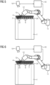
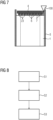
- Figures 5 to 7 show examples of various process steps of a fully automated winding head casting process, the flow chart of which is shown in FIG 8 is shown.
- FIG 5 shows the stator 1 with the winding head 4.
- the polymer layer 7 can be seen, which spans a single gap 6 between two winding ends 23.
- FIG 5 a device 10 which controls a robot arm 11 assigned to it.
- the robot arm 11 carries a nozzle 12 to which thermoplastic hot melt adhesive is supplied.
- the nozzle 12 can also contain a reservoir with thermoplastic hot melt adhesive.
- a thread 13 of the thermoplastic hot melt adhesive is produced by means of the nozzle 12.
- the nozzle 12 is moved in such a way that the thread 13 is applied to the gap 6, for example, by the movement of the nozzle 12 in order to span it, for example, in the form of a net structure - step S1 of the FIG 8 .
- the thread 13 can have a diameter in a range between 50 ⁇ m and 500 ⁇ m, for example.
- thermoplastic hot melt adhesive can be supplied to the nozzle 12 with a working pressure of between 1 bar and 10 bar and/or with a working temperature of between 180°C and 220°C.
- an adhesive based on a polyolefin with a melting temperature of approx. 200°C was used.
- the adhesive was sprayed on at a working temperature T of 220°C and a pressure p of 3 bar.
- the adhesive exited the nozzle 30 at a speed of approx. 5 m/s.
- the distance between the nozzle 14 and the respective flat area was approx. 8 cm, the speed of the nozzle 12 was 600 rpm.
- the loops 13 adhered very well to the winding ends 23 and led to a complete over-tensioning of the gaps 6 to be closed.
- This process step and also the other process steps described below can be recorded, for example, by an optical detection system 14, for example by a camera, e.g. by a 3D camera for the purpose of checking, for example quality control.
- the optical detection system 14 is assigned to the device 10.
- the device 10 can be set up to process and/or analyze what is recorded by the optical detection system 14 and, based on this, to adapt the control of the robot arm 11 accordingly.
- the recorded location and the recorded course of the gaps 6 can be fed to a device 10.
- the device 10 can therefore be able to take the recorded location and the recorded course of the gaps 6 to be sprayed into account accordingly when moving the nozzle 12.
- FIG 6 shows a further process step in which the thread 13 is spun layer by layer and over the entire surface - step S2 of the FIG 8
- the nozzle 12 is moved in such a way that the polymer layer 7 spans several, preferably all, gaps 6.
- the polymer layer 7 remains adhered to the winding ends 23 on the inside of the stator.
- polymer layer 7 can also be applied to the outside of the stator (not shown here).
- FIG 7 shows a process step in which the stator 1 is inserted into the housing 3 and its winding head 4 is cast with a casting compound 100 - step S3 of the FIG 8 . Due to the polymer layer 7, the potting compound 100 does not penetrate into the bore of the stator 1 intended for the rotor.
- the potting compound 100 is a better heat conductor than air and thermally bonds the winding head 4 to the housing 3. This significantly reduces the number of hotspots that arise in the winding head during operation.
- the polymer layer 7 can be at least partially peeled off after the potting compound 100 has cured.
- the stator 1, which is completely encapsulated with the housing 3, can then be used in an electrical, preferably rotary machine.
- An electrical, preferably rotary machine with the stator 1 encapsulated with the housing 3 is thus part of the present disclosure.
- stator and the methods described here enable enclosure by e.g. to save an inner mandrel as a casting tool, which is very complex in conventional casting processes because it is variance-dependent.
- the polymer layer is variance-independent and can be applied fully automatically.
- the polymer layer can be at least partially or almost completely recycled.
- the winding head casting is therefore no longer a complex, largely manual process, but can be carried out completely automatically.
Landscapes
- Engineering & Computer Science (AREA)
- Power Engineering (AREA)
- Manufacturing & Machinery (AREA)
- Manufacture Of Motors, Generators (AREA)
Description
- Die Erfindung betrifft ein Verfahren zum Vergießen eines Wickelkopfs eines Stators einer elektrischen Maschine, wobei der Stator ein Blechpaket mit Nuten und einen Wickelkopf aufweist, wobei in die Nuten Wicklungen eingebracht sind, wobei der Wickelkopf aus aus den Nuten austretenden Wicklungsenden gebildet ist und einen Abstand zu einem Blechpaketende aufweist, wobei die Wicklungsenden in einem Bereich zwischen dem Blechpaketende und dem Wickelkopf derart verlaufen, dass in diesem Bereich zwischen den (einzelnen) Wicklungsenden Zwischenräume entstehen.
- Eine elektrische vorzugsweise rotatorische Maschine mit dem vorgenannten Stator bzw. mit einem Stator, der nach dem vorgenannten Verfahren hergestellt ist oder dessen Wickelkopf nach dem vorgenannten Verfahren vergossen ist. Die elektrische rotatorische Maschine ist vorzugsweise ein Motor.
- Die Statoren und die Wickelkopfvergussverfahren der eingangs genannten Art sind aus dem Stand der Technik hinlänglich bekannt. Niederspannungsmotoren der Leistungsklassen 0,5kW bis 2000kW werden aus Kostengründen mittels Kalttauchverfahren, bzw. Heißtauchverfahren (z.B. Strom-UV-Verfahren) imprägniert. Hierbei werden die Statoren in ein Becken mit Flüssigharz getaucht und im Anschluss thermisch gehärtet. Die geometrischen Zwischenräume der Kupferwicklung werden hierbei großteils mit Harz gefüllt und somit verfestigt, elektrisch zusätzlich isoliert und thermisch mit dem Blechpaket verbunden. In den stirnseitigen Bereichen der Statoren befinden sich die Wickelköpfe, also die notwendigen Kupferstränge, welche die aktiven Bereiche in den Nuten miteinander verbinden. Die Wickelköpfe werden vor dem Imprägnierverfahren nochmals mittels Flächenisolierstoffen (z.B. Einlege-Papiere) ausgestattet, um die Phasen des Motors (z.B. 3 Phasen) elektrisch voneinander zu isolieren, sowie im Form gepresst, komprimiert und bandagiert, um die geometrischen Maße einzuhalten und die vorgesehene Baulänge nicht zu überschreiten (Welle, Rotor, Lagerschild). Eine thermische Anbindung der Wickelköpfe zum Aluminiumgehäuse ist standardmäßig ausschließlich über einen Luftraum/Luftspalt gegeben, welcher mit strömender (konvektiver) Luft gefüllt ist. Die Entwärmung des Wickelkopfes geschieht somit sehr schlecht über die thermischen Kontaktübergänge von Wicklung zur Luft und weiter von Luft auf Aluminium-Gehäuse. Dies ist dahingehend als kritischer und limitierender Faktor der Leistungsklasse des Motors anzusehen, da insbesondere im Wickelkopf sogenannte Hotspots entstehen, d.h. durch sehr hohe Stromstärke (Joulsche Erwärmung) und der zusätzlich geometrisch und mechanisch notwendigen Verdichtung und Fixierung der Drahtbündel, Bereiche entstehen, die deutlich heißer werden als innerhalb der Statornuten. In den Statornuten ist die Entwärmung über das umliegende Eisenblech sehr effizient gegeben. Eine bessere Entwärmung der Wickelköpfe und somit der Wärmeklassen/Leistungsklassen limitierenden Bereiche des Motors ist somit die Problemstellung.
- Um diesem Problem zumindest teilweise entgegenzutreten, können innerhalb der Motoren, z.B. Niederspannungsmotoren durch Flügelräder vorgesehen sein, die eine Entwärmung bewerkstelligen. Das ist eine der günstigsten Varianten. Die Flügelräder sind direkt auf die Welle montiert und treiben in Proportion zur Drehzahl des Motors die Luftkonvektion an, so dass Gehäuse von außen beziehungsweise dessen Kühlrippen mit konvektiver Luft umspült wird beziehungsweise werden. Diese Belüftung wirkt sich jedoch wiederum negativ auf die Leistung bzw. den Wirkungsgrad der Motoren aus und ist fertigungs- und produkttechnisch aufwendig/kostenintensiv. Außerdem wird der Wickelkopf hier nicht aktiv gekühlt, da lediglich die Wärme vom Gehäuse abgeführt werden kann.
- Sind aufgrund höherer Leistungsanforderungen bessere Entwärmungseigenschaften notwendig, so muss der Wickelkopf mittels eines sogenannten Wickelkopfvergusses an das Aluminiumgehäuse thermisch angebunden werden. Hierbei handelt es sich um einen mit wärmeleitfähigen Partikeln gefüllten Formstoff (Reaktivharz, z.B. Epoxy, Polyurethan oder Polyester. Die Füllstoffpartikel sind je nach gewünschter Wärmeleitfähigkeit und gewünschtem Preisniveau des Formstoffes aus Quarzmehl, Quarzgut, Bornitrid oder Aluminiumoxid (Liste nicht vollständig) in einer optimierten Korngrößenverteilung als Mikropartikel in der Matrix (Reaktivharz) dispergiert, sodass eine noch möglichst dünnflüssige, fließfähige Formmasse vorhanden ist. Der Füllgrad des Füllstoffes in der Matrix beträgt zwischen 20 und 70 Vol.-%, je nach gewünschter Fließfähigkeit bei Verarbeitungstemperatur - also prozessabhängig.
- Neben den Materialkosten sind die Prozesskosten eines Wickelkopfvergusses deutlich markanter, da die imprägnierten Statoren aus dem Standardfertigungsfluss ausgeschleust werden müssen und mittels Vergussformen für den Wickelkopfverguss vorbereitet werden müssen (erst eine Seite, dann die andere). Hierbei wird eine Art Innendorn in die Bohrung des Stators formschlüssig eingebracht, um Benetzen der Innenbohrung mit der Vergussmasse zu verhindern. Anschließend wird der Stator ggf. auf eine erhöhte Temperatur erhitzt (z.B. 80°C um die Fließfähigkeit der Vergussmasse zu verbessern). Im Anschluss wird die Vergussmasse in das so eingehauste Wickelkopfreservoir gegossen. Im Anschluss wird die Masse über mehrere Stunden bei ca. 150°C hinweg z.B. im Heißluftofen gehärtet. Nach der Härtung (und der Abkühlung) wird die jeweils andere Wickelkopfseite ebenso vergossen). Der Vergusskörper umschließt somit nach den beiden Einzelprozessen beide Wickelköpfe sowohl radial innenseitig, als auch radial außenseitig, wohingegen der Wärmefluss beim geschlossenen Motor großteils radial nach außen hin zum Aluminiumgehäuse geschieht. Die vollständige Umschließung ist vielmehr ein Prozess-geschuldetes Phänomen, da der innenliegende Dorn als Gehäusewandung dient und im Anschluss entfernt und gereinigt werden muss.
- In Summe handelt es sich bei dem Wickelkopfverguss um einen sehr aufwändigen Prozess (Zeit, Energie und Materialkosten), welcher zudem mehr Material in den Motor bringt, als tatsächlich für die angestrebte Eigenschaft notwendig wäre (Entwärmung des Wickelkopfes in Richtung Gehäuse, radial nach au-βen).
- In der
DE 10 2005 017 113 A1 ist eine Schutzschichtanordnung für einen Wickelkopf einer elektrischen Maschine bestimmt. Sie hat eine erste und eine zweite Deckschicht. Die erste und die zweite Deckschicht umschließen eine elektrische Leiteranordnung des Wickelkopfs. Die erste Deckschicht besteht aus einem im gesamten Anwendungstemperaturbereich gelartigen und selbstheilenden Polymermaterial. Die zweite Deckschicht umgibt die erste Deckschicht unmittelbar. Sie besteht aus einem härteren Material als die erste Deckschicht. - Die Aufgabe der vorliegenden Erfindung kann somit darin gesehen werden, ein Wickelkopfvergussverfahren bereitzustellen, das kostensparend vereinfacht werden kann.
- Die Aufgabe wird mit einem eingangs genannten Verfahren gemäß des unabhängigen Anspruchs 1 erfindungsgemäß dadurch gelöst, dass zumindest einer der Zwischenräume mit einer Polymerschicht derart überspannt ist, dass ein Durchfluss von flüssigem Medium durch den zumindest einen überspannten Zwischenraum durch verhindert ist.
- Dass der Wickelkopf einen Abstand zu dem Blechpaketende aufweist, bedeutet, dass es Wicklungsabschnitte gibt, die zwischen dem Wickelkopf und dem Blechpaket liegen und somit weder in dem (später zu vergießenden) Wickelkopf noch in dem Blechpaket liegen.
- Somit wird ein Verfahren bereitgestellt, bei dem Wickelkopfverguss ohne Zusatzwerkzeug erfolgen kann.
- Bei einer Ausführungsform kann es zweckmäßig sein, wenn alle Zwischenräume mit der Polymerschicht überspannt sind.
- Bei einer Ausführungsform kann vorgesehen sein, wenn die Polymerschicht statorinnenseitig und/oder statoraußenseitig angebracht ist.
- Bei einer Ausführungsform kann vorgesehen sein, dass der Kunststoffkleber in Form von Fäden aufgespritzt ist, so dass die Fäden in Form überlappender Schleifen aufeinander aufgeschleudert sind und eine Netzstruktur bilden, wobei die Netzstruktur den zumindest einen der Zwischenräume überspannt.
- Die Aufgabe wird außerdem mit einem eingangs genannten Verfahren zum Herstellen eines Stators erfindungsgemäß dadurch gelöst, dass zumindest einer der Zwischenräume mit einer Polymerschicht derart abgedeckt wird, dass ein Durchfluss von flüssigem Medium durch den zumindest einen abgedeckten Zwischenraum durch verhindert wird.
- Bei einer Ausführungsform kann vorgesehen sein, dass die Polymerschicht durch Aufspritzen und/oder Aufschleudern und/oder Aufsprühen eines klebstoffhaltigen Mediums mittels einer Düse erzeugt wird.
- Bei einer Ausführungsform kann zweckmäßig sein, wenn während des Erzeugens die Düse derart verfahren wird, dass das klebstoffhaltige Medium durch die Verfahrbewegung der Düse derart schichtweise und flächendeckend aufgetragen wird, dass das klebstoffhaltige Medium den zumindest einen Zwischenraum überspannt.
- Bei einer Ausführungsform kann vorgesehen sein, dass das klebstoffhaltige Medium einen thermoplastischen Schmelzklebstoff umfasst.
- Bei einer Ausführungsform kann mit Vorteil vorgesehen sein, dass mittels einer Düse ein Faden eines thermoplastischen Schmelzklebstoffs erzeugt wird, während des Erzeugens die Düse derart verfahren wird, dass der Faden durch die Verfahrbewegung der Düse derart aufgetragen wird, dass der Faden in Form überlappender Schleifen und/oder Schlingen aufgeschleudert wird, um eine Netzstruktur zu bilden, wobei die Netzstruktur den zumindest einen der Zwischenräume überspannt.
- Bei einer Ausführungsform kann vorgesehen sein, dass der Faden schichtweise und flächendeckend in Form von Schlingen aufgetragen wird.
- Bei einer Ausführungsform kann vorgesehen sein, dass alle Zwischenräume mit einer Polymerschicht abgedeckt werden.
- Bei einer Ausführungsform kann vorgesehen sein, dass die Polymerschicht statorinnenseitig und/oder statoraußenseitig angebracht wird.
- Beim statorinnenseitigen Anbringen der Polymerschicht kann der Stator bereits im Gehäuse eingehaust sein.
- Beim statoraußenseitig Anbringen der Polymerschicht kann kein Polymermaterial auf die Innenseite des Stators gelangen.
- Bei einer Ausführungsform kann vorgesehen sein, dass das Auftragen des thermoplastischen Schmelzklebstoffs vollautomatisch, insbesondere mit einem Roboter erfolgt.
- Bei einer Ausführungsform kann vorgesehen sein, dass die Polymerschicht nach dem Vergießen und Aushärten der Vergussmasse zumindest teilweise entfernt wird.
- Bei einer Ausführungsform kann es zweckdienlich sein, wenn beide Wickelköpfe des Stators wie oben beschrieben mit einer Polymerschicht versehen und vorzugsweise vergossen werden.
- Weitere Merkmale, Eigenschaften und Vorteile der vorliegenden Erfindung ergeben sich aus der nachfolgenden Beschreibung unter Bezugnahme auf die beiliegenden Figuren. Darin zeigen schematisch:
- FIG 1
- einen vergrößerten Ausschnitt eines Stators einer rotatorischen elektrischen Maschine in perspektivischer Ansicht,
- FIG 2
- einen Schnitt durch das Blechpaket aus
FIG 1 , - FIG 3
- einen vergrößerten Ausschnitt der
FIG 1 , - FIG 4
- einen Wickelkopfvergussprozess nach dem Stand der Technik,
- FIG 5 bis 7
- verschiedene Verfahrensschritte eines Wickelkopfvergussverfahrens, und
- FIG 8
- ein Flussdiagramm des Wickelkopfvergussverfahrens.
- In den Ausführungsbeispielen und Figuren können gleiche oder gleich wirkende Elemente jeweils mit den gleichen Bezugszeichen versehen sein. Die Bezugszeichen sind lediglich zur Vereinfachung der Findung der mit den Bezugszeichen versehenen Elemente vorgesehen und haben keine einschränkende Wirkung auf den unter den Schutz gestellten Gegenstand inne.
-
FIG 1 zeigt beispielhaft einen vergrößerten Ausschnitt eines Stators 1 einer rotatorischen elektrischen Maschine in perspektivischer Ansicht, sodass die Innenseite nicht aber die Außenseite des Stators 1 zu sehen ist. Die elektrische Maschine kann im Einzelfall als lineare elektrische Maschine ausgebildet sein. Andere üblicherweise vorhandene Komponenten der elektrischen rotatorischen Maschine, wie z.B. Rotor, Rotorwelle, Lagerschilde etc., sind inFIG 1 nicht dargestellt. - Der Stator 1 weist ein Blechpaket 2 mit einer Vielzahl von einzelnen Statorblechen auf.
-
FIG 2 zeigt einen Schnitt durch das Blechpaket 2. AusFIG 2 ist insbesondere erkennbar, dass in das Blechpaket 2 (statorinnenseitig) Nuten 21 eingebracht sind. Das Herstellen des Blechpakets 2 erfolgt auf konventionelle Art und Weise und muss daher nicht näher erläutert werden. - Die Nuten 21 können - wie allgemein üblich - dadurch in das Blechpaket 2 eingebracht werden, dass bereits die Statorbleche entsprechend ausgestanzt werden.
- In die Nuten 21 sind Wicklungen 22 eines Statorwicklungssystems eingebracht. Die Wicklungen 22 können ein mehrphasiges, beispielsweise ein dreiphasiges Statorwicklungssystem bilden. Die Wicklungen 22 der einzelnen Phasen werden in der Regel sequenziell nacheinander in die Nuten 21 eingebracht. Das Einführen der Wicklungen 22 als solches erfolgt auf konventionelle Art und Weise und muss daher nicht näher erläutert werden. Die Wicklungen 22 können nach Bedarf als sogenannte wilde Wicklungen oder als sogenannte gelegte Wicklungen ausgebildet sein. Die Wicklungen 22, z.B. Runddrähte, Lackdrähte, können beispielsweise als Kupferstränge aus einer Vielzahl von Kupferdrähten gebildet sein.
-
FIG 1 lässt weiterhin erkennen, dass der Stator 1 in ein Gehäuse 3, z.B. aus Aluminium gefügt ist. -
FIG 1 zeigt einen Wickelkopf 4 des Stators 1. Der andere Wickelkopf liegt auf einem dem inFIG 1 gezeigten Ende des Stators 1 gegenüberliegenden Ende und ist der Einfachheit halber nicht dargestellt. - Der Wickelkopf 4 wird durch freie, nicht in die Nuten 21 eingebrachte Wicklungensenden 23 gebildet. Dabei werden die aus den Nuten 21 in Längsrichtung des Stators 1 hervorspringenden Wicklungensenden 23 in einem Abstand 5 von einem Blechpaketende 24 (einer Stirnseite des Stators 1) zu dem Wickelkopf 4 zusammengefasst beziehungsweise zusammengebunden. Das Zusammenbinden kann beispielsweise mit einem Klebeband o.Ä. erfolgen. Das Bilden des Wickelkopfes 4 aus den Wicklungensenden 23 als solches erfolgt auf konventionelle Art und Weise und muss daher nicht näher erläutert werden.
- Der Abstand 5 kann beispielsweise etwa 5 mm bis 150 mm betragen, je nach Größe des Stators 1.
- Zwischen dem Blechpaketende 24 und dem Wickelkopf 4 verlaufen die Wicklungenenden 23 in etwa parallel zueinander und auch in etwa parallel zu der Längsachse des Stators 1.
-
FIG 1 ist weiterhin zu entnehmen, dass die Wicklungen 22 außerhalb des Blechpakets 2 in Umfangsrichtung des Stators 1 beziehungsweise des Wickelkopfes 4 voneinander beabstandet sind, sodass zwischen den Wicklungen 22 Zwischenräume 6 gebildet sind. - Von den Nuten 21, den Wicklungen 22, den Wicklungsenden 23 und den Zwischenräumen 6 sind in den Figuren nur einige wenige mit ihrem Bezugszeichen versehen, um die Figuren nicht unnötig zu überfrachten.
- Die Zwischenräume 6, vorzugsweise alle Zwischenräume 6 sind mit einer Polymerschicht 7 überspannt beziehungsweise abgedeckt beziehungsweise bedeckt. Die Polymerschicht 7 haftet vorzugsweise ohne weitere Hilfs-/Haftmittel an den Wicklungsenden 23.
- Die Polymerschicht 7 kann eine Dicke von etwa 0,1 mm bis 3 mm aufweisen, vorzugsweise zwischen 0,5 mm und 1,5 mm, beispielsweise in etwa 1,0 mm aufweisen.
-
FIG 3 zeigt einen vergrößerten Ausschnitt derFIG 1 .FIG 3 lässt erkennen, dass ein Zwischenraum 6 zwischen den Wicklungsenden 23 mit der Polymerschicht 7 überspannt beziehungsweise abgedeckt beziehungsweise bedeckt ist. Die Polymerschicht kann sich in Umfangsrichtung des Stators 1 zumindest zwischen den beiden benachbarten Wicklungsenden 23 und in Längsrichtung des Stators 1 vom Blechpaketende 24 bis zum Wickelkopf 4 erstrecken, um die Zwischenräume derart abzudecken, dass kein Durchfluss von flüssigem Medium, insbesondere von Wickelkopf-Vergussmasse, durch den Zwischenraum 6 durch (also von Statoraußenseite zu der Statorinnenseite oder umgekehrt) mehr möglich ist. - Die Polymerschicht 7 überspannt und verschließt somit den Zwischenraum 6 und haftet an beiden Wicklungsenden 23, durch die der Zwischenraum 6 gebildet ist.
- Als Wickelkopf-Vergussmasse oder einfach Vergussmasse kann z.B. flüssiger Formstoff mit wärmeleitfähigen Partikeln verwendet werden. Der Formstoff kann beispielsweise Reaktivharz, z.B. Epoxy, Polyurethan oder Polyester. Die als Mikropartikel in der Matrix eingebetteten wärmeleitfähigen Partikeln können beispielsweise Quarzmehl-, Quarzgut-, Bornitrid- oder Aluminiumoxid-Partikeln sein. Diese Aufzählungen der Materialien sind nicht vollständig.
- Auf die beschriebene Weise überspannt die Polymerschicht 7 vorzugsweise jeden Zwischenraum 6.
- Beispielsweise erstreckt sich die Polymerschicht 7 in die Längsrichtung des Stators für etwa 5 mm bis 150 mm je nach Größe des Stators 1.
- Dabei kann die Polymerschicht 6 die Zwischenräume statorinnenseitig (wie in
FIG 1 undFIG 3 gezeigt) und/oder statoraußenseitig (nicht gezeigt) überspannen beziehungsweise abdecken. - Beispielsweise kann die Polymerschicht als ein Band ausgebildet sein, welches eine Breite größer-gleich (≥) als der Abstand 5 aufweist. Darüber hinaus kann das Band in sich geschlossen sein, so dass es einen statorinnenseitigen und/oder statoraußenseitigen Bereich überspannt beziehungsweise abdeckt beziehungsweise bedeckt, an welchen Bereich die Zwischenräume 6 angrenzen. Die Polymerschicht 7 kann somit als ein statorinnenseitiger und/oder statoraußenseitiger Kragen ausgebildet sein.
- Vorzugsweise ragt die Polymerschicht 7 nicht in die für einen Rotor vorgesehene Bohrung des Stators 1 hinein.
- Die Polymerschicht 7 kann ausgehärteten Kunststoffkleber umfassen, vorzugsweise aus dem ausgehärteten Kunststoffkleber bestehen.
- Beispielsweise kann thermoplastischer Schmelzklebstoff, z.B. Polyolefin oder Polyamid verwendet werden. Konkret wurden gute Ergebnisse erzielt mit den Materialien 3M Scotch Weld 3731, 3789 und 3779 der Firma 3M, wobei das erstgenannte Material ein Polyolefin ist und die beiden anderen Materialien Polyamide sind.
- Dabei kann der Kunststoffkleber in Form von Fäden aufgespritzt sein, so dass die Fäden in Form überlappender Schleifen aufeinander aufgeschleudert sind und eine Netzstruktur bilden, die den Zwischenraum 6 oder die Zwischenräume 6 überspannt. Die Fäden können einen Durchmesser ca. 50-500pm aufweisen.
- Die Polymerschicht 7 kann an den Wicklungsenden 23 ohne weitere Hilfs-/Haftmittel haften. Dies bedeutet insbesondere, dass es keiner weiteren Kleberschicht o.Ä. bedarf, damit die Polymerschicht 7 an den Wicklungsenden 23 haftet und die Zwischenräume 6 und die Innenseite beziehungsweise die Bohrung des Stators 1 flüssigdicht macht.
- Die Polymerschicht 7 kann auch RT (Raumtemperatur, ca. 25°C) härtende ausgehärtete Klebstoffe umfassen beziehungsweise aus solchen ausgebildet sein. Der verwendete Kunststoffkleber kann eine Faserverstärkung umfassen. Die Polymerschicht 7 kann durch Aufsprühen des Kunststoffklebers gebildet sein und beispielsweise Form einer Sprühtapete aufweisen. Der Kunststoffkleber kann chemisch härtend sein, so z.B. können Duromere Kunststoffe verwendet werden, die beispielsweise UVhärtend sind. Es können physikalisch härtende Kunststoffe als Kunststoffkleber verwendet werden. Es können gefüllte Kunststoffe (Fasern, Partikeln) als Kunststoffkleber verwendet werden, sofern diese applizierbar bleiben, z.B. in Form einer Sprühtapete. Es können auch lösemittelhaltige Kunststoffe als Kunststoffkleber verwendet werden, welche sich durch Verdunstung des Lösemittels verfestigen (z.B. Haarlack, PVA). Es können Reaktivharze (z.B. Epoxy, PEI, PU) als Kunststoffkleber verwendet werden.
- Obwohl in
FIG 1 und3 nur auf den Wickelkopf 4 Bezug genommen wird, versteht es sich, dass ein dem Wickelkopf 4 gegenüberliegenden Wickelkopf ebenfalls eine Polymerschicht aufweisen kann, die auf die gleiche Weise wie die oben beschriebene Polymerschicht 7 angeordnet sein kann und die entsprechenden Zwischenräume überspannt, um Durchfluss von flüssigem Medium in die für den Rotor vorgesehene Statorbohrung zu vermeiden. -
FIG 4 verdeutlicht die in der Beschreibungseinleitung erwähnten Probleme des Standes der Technik.FIG 4 lässt den Stator 1 derFiguren 1 bis 3 erkennen, der in ein Gehäuse 3 gefügt ist. Zwischen den Wicklungsenden 23, die zwischen dem Blechpaketende 24 und dem Wickelkopf 4 verlaufen, sind Zwischenräume 6 vorhanden.FIG 4 lässt erkennen, dass beim Wickelkopfvergießen mit einer Vergussmasse 100 diese durch die Zwischenräume 6 in die Statorbohrung fließt, wenn kein Zusatzwerkzeug verwendet wird. Das Zusatzwerkzeug kann z.B. ein Dorn oder ein großes Kunststoffrohr sein, welches das Hineinfließen in die Statorbohrung verhindert. Das Zusatzwerkzeug muss immer abgedichtet sein und hängt von dem Durchmesser der Bohrung ab, ist also abhängig von der Motorgröße. - Die Polymerschicht 7 ist weder von dem Durchmesser der Bohrung noch von der Maschinengröße abhängig.
-
Figuren 5 bis 7 zeigen beispielhaft verschiedene Verfahrensschritte eines vollautomatisierten Wickelkopfvergussverfahrens, dessen Flussdiagramm inFIG 8 dargestellt ist. - Es wird also nun auf
Figuren 5 bis 8 Bezug genommen. -
FIG 5 zeigt den Stator 1 mit dem Wickelkopf 4. Darüber hinaus ist die Polymerschicht 7 zu erkennen, die einen einzigen Zwischenraum 6 zwischen zwei Wicklungsenden 23 überspannt. - Darüber hinaus zeigt
FIG 5 eine Einrichtung 10, die einen ihr zugeordneten Roboterarm 11 steuert. An seinem freien Ende trägt der Roboterarm 11 eine Düse 12, der thermoplastischer Schmelzklebstoff zugeführt wird. Die Düse 12 kann auch einen Speicher mit thermoplastischen Schmelzklebstoff enthalten. Dabei wird mittels der Düse 12 ein Faden 13 des thermoplastischen Schmelzklebstoffs erzeugt. Während des Erzeugens wird die Düse 12 derart verfahren, dass der Faden 13 durch die Verfahrbewegung der Düse 12 beispielsweise auf den Zwischenraum 6 aufgetragen wird, um diese beispielsweise in Form einer Netzstruktur zu überspannen - Schritt S1 derFIG 8 . - Dabei können bei dem Roboterarm 11 alle drei räumlichen Freiheitsgrade ausgenutzt werden. Der Faden 13 kann einen Durchmesser beispielsweise in einem Bereich zwischen 50 µm und 500 µm aufweisen.
- Der thermoplastische Schmelzklebstoff kann der Düse 12 mit einem Arbeitsdruck zugeführt werden, der zwischen 1 bar und 10 bar liegt, und/oder mit einer Arbeitstemperatur, die zwischen 180°C und 220°C liegt.
- In einem konkreten Versuch wurde beispielsweise ein Klebstoff auf der Basis eines Polyolefins mit einer Schmelztemperatur von ca. 200°C verwendet. Der Klebstoff wurde mit einer Arbeitstemperatur T von 220°C und einem Druck p von 3 bar aufgespritzt. Der Klebstoff trat mit einer Geschwindigkeit von ca. 5 m/s aus der Düse 30 aus. Der Abstand der Düse 14 von dem jeweiligen flächigen Bereich betrug ca. 8 cm, die Drehzahl der Düse 12 lag bei 600 U/min. Die Schlingen 13 hafteten sehr gut auf den Wicklungsenden 23 und führten zu einer vollständigen Überspannung der zu verschließenden Zwischenräumen 6.
- Dieser Prozessschritt und auch die weiteren nachfolgend beschriebenen Prozessschritte können beispielsweise von einem optischen Erfassungssystem 14, beispielsweise von einer Kamera, z.B. von einer 3D-Kamera zwecks Kontrolle, beispielsweise Qualitätskontrolle erfasst werden. Das optische Erfassungssystem 14 ist der Einrichtung 10 zugeordnet. Die Einrichtung 10 kann dazu eingerichtet sein, das von dem optischen Erfassungssystem 14 Aufgenommene zu verarbeiten und/oder zu analysieren und basierend darauf die Steuerung des Roboterarms 11 dementsprechend anzupassen. Dabei können der erfasste Ort und der erfasste Verlauf der Zwischenräume 6 einer Einrichtung 10 zugeführt werden. Die Einrichtung 10 kann dadurch in der Lage sein, den erfassten Ort und den erfassten Verlauf der zu bespritzenden Zwischenräume 6 beim Verfahren der Düse 12 entsprechend zu berücksichtigen.
-
FIG 6 zeigt einen weiteren Prozessschritt, bei welchem der Faden 13 schichtweise und flächendeckend aufgeschleudert wird - Schritt S2 derFIG 8 . Die Düse 12 wird so verfahren, dass die Polymerschicht 7 mehrere vorzugsweise alle Zwischenräume 6 überspannt. Die Polymerschicht 7 bleibt statorinnenseitig an den Wicklungsenden 23 haften. - Diese Art, die Polymerschicht 7 aufzutragen, ist auch dann möglich, wenn der Stator 1 bereits in das Gehäuse 3 gefügt ist.
- Es versteht sich, dass die Polymerschicht 7 auch statoraußenseitig aufgetragen werden kann (hier nicht gezeigt).
-
FIG 7 zeigt einen Prozessschritt, bei welchem der Stator 1 in das Gehäuse 3 gefügt wird und sein Wickelkopf 4 mit einer Vergussmasse 100 vergossen wird - Schritt S3 derFIG 8 . Dabei dringt die Vergussmasse 100 aufgrund der Polymerschicht 7 nicht in die für den Rotor vorgesehene Bohrung des Stators 1 ein. - Die Vergussmasse 100 ist ein besserer Wärmeleiter als die Luft und bindet den Wickelkopf 4 an das Gehäuse 3 thermisch an. Dadurch die Anzahl der im Betrieb im Wickelkopf entstehenden Hotspots deutlich reduziert.
- Darüber hinaus kann die Polymerschicht 7, nachdem die Vergussmasse 100 ausgehärtet ist, zumindest teilweise abgezogen werden.
- Der mit dem Gehäuse 3 fertig vergossene Stator 1 kann anschließend bei einer elektrischen vorzugsweise rotatorischen Maschine verwendet werden. Eine elektrische vorzugsweise rotatorischen Maschine mit dem mit dem Gehäuse 3 vergossenen Stator 1 ist somit ein Teil der vorliegenden Offenbarung.
- Zusammengefasst, ermöglichen der hier beschriebene Stator und die hier beschriebenen Verfahren, eine Einhausung durch z.B. einen Innendorn als Vergusswerkezeug, welche bei herkömmlichen Vergussprozessen sehr aufwändig ist, da sie varianzabhängig ist, einzusparen.
- Die Polymerschicht ist varianzunabhängig und kann vollautomatisiert aufgebracht werden. Außerdem kann die Polymerschicht zumindest teilweise oder fast vollständig recyclet werden.
- Der Wickelkopfverguss stellt sich somit nichtmehr als aufwändiger, großteils händischer, Prozess dar, sondern kann komplett automatisiert vollzogen werden.
- Hierdurch wird es kostengünstig und kosteneffizient realisierbar kleinere Achshöhen mit hoher Variantenvielfalt mittels eines Wickelkopfvergusses thermisch zu verbessern, sodass eine höhere Leistungsklasse erreicht werden kann oder die generelle Betriebstemperatur bei gleicher Leistung gesenkt wird, was im Umkehrschluss zu einer höheren Lebensdauer der Maschine führt.
- Obwohl die Erfindung im Detail durch bevorzugte Ausführungsbeispiele näher illustriert und beschrieben wurde, ist die Erfindung nicht durch die offenbarten Beispiele eingeschränkt. Variationen hiervon können vom Fachmann abgeleitet werden, ohne den Schutzumfang der Erfindung, wie er durch die nachfolgenden Patentansprüche definiert wird, zu verlassen. Beispielsweise können jene Merkmale, die im Kontext der Verfahren offenbart wurden, auch zur Weiterbildung des beschriebenen Stators verwendet werden und umgekehrt.
Claims (8)
- Verfahren zum Vergießen eines Wickelkopfs (4) eines Stators (1), wobei- ein Stator (1) bereitgestellt wird, der ein Blechpaket (2) mit Nuten (21) und einen Wickelkopf (4) aufweist, wobei in die Nuten (21) Wicklungen (22) eingebracht sind, wobei der Wickelkopf (4) aus aus den Nuten (21) austretenden Wicklungsenden (23) gebildet ist und einen Abstand (5) zu einem Blechpaketende (24) aufweist, wobei die Wicklungsenden (23) in einem Bereich zwischen dem Blechpaketende (24) und dem Wickelkopf (4) derart verlaufen, dass in diesem Bereich zwischen den Wicklungsenden (23) Zwischenräume (6) entstehen,- der Stator (1) in ein Gehäuse (3) einer elektrischen Maschine gefügt wird, und der Wickelkopf (4) des Stators (1) mit einer Vergussmasse vergossen wird,
dadurch gekennzeichnet, dass- zumindest einer der Zwischenräume (6) mit einer Polymerschicht (7) vor dem Vergießen derart überspannt wird, dass ein Durchfluss von einer Vergussmasse (100) durch den zumindest einen überspannten Zwischenraum (6) durch verhindert wird. - Verfahren nach Anspruch 1, wobei die Polymerschicht (7) nach dem Vergießen und Aushärten der Vergussmasse zumindest teilweise entfernt wird.
- Verfahren nach Anspruch 1 oder 2, wobei die Polymerschicht (7) durch Aufspritzen und/oder Aufschleudern und/oder Aufsprühen eines klebstoffhaltigen Mediums mittels einer Düse (12) erzeugt wird.
- Verfahren nach einem der Ansprüche 1 bis 3, wobei während des Erzeugens die Düse (12) derart verfahren wird, dass das klebstoffhaltige Medium durch die Verfahrbewegung der Düse (12) derart schichtweise und flächendeckend aufgetragen wird, dass das klebstoffhaltige Medium den zumindest einer der Zwischenräume (6) überspannt.
- Verfahren nach einem der Ansprüche 1 bis 4, wobei mittels einer Düse (12) ein Faden (13) eines thermoplastischen Schmelzklebstoffs erzeugt wird, wobei während des Erzeugens die Düse (12) derart verfahren wird, dass der Faden (13) durch die Verfahrbewegung der Düse (12) derart aufgetragen wird, dass der Faden in Form überlappender Schleifen aufgeschleudert wird, um eine Netzstruktur zu bilden, wobei die Netzstruktur den zumindest einen der Zwischenräume (6) überspannt.
- Verfahren nach einem der Ansprüche 1 bis 5, wobei alle Zwischenräume (6) mit einer Polymerschicht (7) abgedeckt werden.
- Verfahren nach einem der Ansprüche 1 bis 6, wobei die Polymerschicht (7) statorinnenseitig und/oder statoraußenseitig angebracht wird.
- Verfahren nach einem der Ansprüche 1 bis 7, wobei das Auftragen des thermoplastischen Schmelzklebstoffs vollautomatisch, insbesondere mit einem Roboter (11) erfolgt.
Applications Claiming Priority (2)
| Application Number | Priority Date | Filing Date | Title |
|---|---|---|---|
| EP21166276.2A EP4068577A1 (de) | 2021-03-31 | 2021-03-31 | Stator für eine elektrische rotatorische maschine |
| PCT/EP2022/057863 WO2022207475A1 (de) | 2021-03-31 | 2022-03-25 | Stator für eine elektrische rotatorische maschine |
Publications (2)
| Publication Number | Publication Date |
|---|---|
| EP4248552A1 EP4248552A1 (de) | 2023-09-27 |
| EP4248552B1 true EP4248552B1 (de) | 2024-08-28 |
Family
ID=75339530
Family Applications (2)
| Application Number | Title | Priority Date | Filing Date |
|---|---|---|---|
| EP21166276.2A Withdrawn EP4068577A1 (de) | 2021-03-31 | 2021-03-31 | Stator für eine elektrische rotatorische maschine |
| EP22717619.5A Active EP4248552B1 (de) | 2021-03-31 | 2022-03-25 | Stator für eine elektrische rotatorische maschine |
Family Applications Before (1)
| Application Number | Title | Priority Date | Filing Date |
|---|---|---|---|
| EP21166276.2A Withdrawn EP4068577A1 (de) | 2021-03-31 | 2021-03-31 | Stator für eine elektrische rotatorische maschine |
Country Status (4)
| Country | Link |
|---|---|
| US (1) | US12021420B2 (de) |
| EP (2) | EP4068577A1 (de) |
| CN (1) | CN117099288A (de) |
| WO (1) | WO2022207475A1 (de) |
Families Citing this family (2)
| Publication number | Priority date | Publication date | Assignee | Title |
|---|---|---|---|---|
| DE102022212976A1 (de) * | 2022-12-01 | 2024-06-06 | Robert Bosch Gesellschaft mit beschränkter Haftung | Statoranordnung und Verfahren zum Herstellen einer Statoranordnung |
| EP4693835A1 (de) * | 2024-08-05 | 2026-02-11 | Innomotics GmbH | Verfahren zur herstellung eines wickelkopfschutzes eines stators durch träufelbeschichtung |
Family Cites Families (4)
| Publication number | Priority date | Publication date | Assignee | Title |
|---|---|---|---|---|
| DE3133734C2 (de) * | 1981-08-26 | 1985-04-25 | Loher Gmbh, 8399 Ruhstorf | Verfahren zum Überziehen bzw. Vergießen von Wickelköpfen elektrischer Vorrichtungen sowie Anwendung zum Tränken |
| DE10324680A1 (de) * | 2003-05-30 | 2004-12-23 | Siemens Ag | Elektrische Maschine mit druckfest gekapseltem Stator |
| DE102005017113B4 (de) * | 2005-04-13 | 2007-04-12 | Siemens Ag | Schutzschichtanordnung für einen Wickelkopf einer elektrischen Maschine |
| EP3772158B1 (de) * | 2019-08-02 | 2021-09-29 | Siemens Aktiengesellschaft | Isolation von wicklungsenden einer statorwicklung |
-
2021
- 2021-03-31 EP EP21166276.2A patent/EP4068577A1/de not_active Withdrawn
-
2022
- 2022-03-25 EP EP22717619.5A patent/EP4248552B1/de active Active
- 2022-03-25 WO PCT/EP2022/057863 patent/WO2022207475A1/de not_active Ceased
- 2022-03-25 US US18/284,176 patent/US12021420B2/en active Active
- 2022-03-25 CN CN202280026566.4A patent/CN117099288A/zh active Pending
Also Published As
| Publication number | Publication date |
|---|---|
| US12021420B2 (en) | 2024-06-25 |
| CN117099288A (zh) | 2023-11-21 |
| US20240088763A1 (en) | 2024-03-14 |
| EP4248552A1 (de) | 2023-09-27 |
| EP4068577A1 (de) | 2022-10-05 |
| WO2022207475A1 (de) | 2022-10-06 |
Similar Documents
| Publication | Publication Date | Title |
|---|---|---|
| EP1153726B1 (de) | Isolierung von Statorwicklungen im Spitzgussverfahren | |
| DE102019111729A1 (de) | Vorrichtung zum kühlen eines elektromotors und verfahren zur herstellung desselben | |
| EP4248552B1 (de) | Stator für eine elektrische rotatorische maschine | |
| WO2014117773A2 (de) | Elektromaschine mit einer kühleinrichtung und verfahren zu deren herstellung | |
| EP1573882B1 (de) | Spulen für elektrische maschinen in litzentechnik | |
| DE102020101035A1 (de) | Elektromotor mit verbesserter wärmeableitung und produktivität und verfahren zur herstellung desselben | |
| WO1991019347A1 (de) | Verfahren zur herstellung des ständers einer elektrischen maschine, vorzugsweise drehstromgenerator | |
| DE10023204A1 (de) | Isolierung von Statorwicklungen durch Schrumpfschläuche | |
| WO2023217471A1 (de) | Rotor für eine elektrische traktionsmaschine eines kraftfahrzeugs sowie elektrische traktionsmaschine | |
| DE102007006513A1 (de) | Statoranordnung und Herstellungsverfahren | |
| WO2016050528A1 (de) | Aktivteil als rotor oder stator, ein verfahren zur herstellung eines solchen aktivteils und eine elektrische maschine | |
| WO2023117716A1 (de) | Verfahren zum herstellen eines rotors für eine elektrische maschine und elektrische maschine | |
| EP1154542A1 (de) | Isolierung von Spulen | |
| WO2015071091A2 (de) | Elektrische maschine mit vergossenem wickelkopf | |
| EP1573883B1 (de) | Extrudierte elastische isolierung für leiter von elektrischen maschinen | |
| DE19860412A1 (de) | Innenglimmschutz für Statorleiter in Motoren und Generatoren | |
| EP4068596A1 (de) | Verfahren zur herstellung eines stators einer dynamoelektrischen maschine | |
| EP1742335B1 (de) | Stator und Verfahren zur Herstellung eines Stators eines elektrischen Antriebsmotors | |
| EP2975736B1 (de) | Stator einer rotierenden elektrischen Maschine und dessen Herstellung | |
| DE2912684C2 (de) | Von Kraftstoff durchströmter Elektromotor in einem Kraftstoff-Förderaggregat | |
| DE212021000371U1 (de) | Statorbaugruppe für eine elektrische Maschine, elektrische Maschine und Elektrowerkzeug | |
| DE102021214589A1 (de) | Statoranordnung, elektrische Maschine mit einer solchen Statoranordnung sowie Verfahren zur Herstellung einer Statoranordnung | |
| EP1753113B1 (de) | Statorverguss | |
| WO2017036745A1 (de) | Elektrische maschine und verfahren zum betrieb einer solchen elektrischen maschine sowie herstellverfahren | |
| WO2023227339A1 (de) | Verfahren zur herstellung eines stators einer dynamoelektrischen maschine |
Legal Events
| Date | Code | Title | Description |
|---|---|---|---|
| STAA | Information on the status of an ep patent application or granted ep patent |
Free format text: STATUS: UNKNOWN |
|
| STAA | Information on the status of an ep patent application or granted ep patent |
Free format text: STATUS: THE INTERNATIONAL PUBLICATION HAS BEEN MADE |
|
| PUAI | Public reference made under article 153(3) epc to a published international application that has entered the european phase |
Free format text: ORIGINAL CODE: 0009012 |
|
| STAA | Information on the status of an ep patent application or granted ep patent |
Free format text: STATUS: REQUEST FOR EXAMINATION WAS MADE |
|
| 17P | Request for examination filed |
Effective date: 20230622 |
|
| AK | Designated contracting states |
Kind code of ref document: A1 Designated state(s): AL AT BE BG CH CY CZ DE DK EE ES FI FR GB GR HR HU IE IS IT LI LT LU LV MC MK MT NL NO PL PT RO RS SE SI SK SM TR |
|
| GRAP | Despatch of communication of intention to grant a patent |
Free format text: ORIGINAL CODE: EPIDOSNIGR1 |
|
| STAA | Information on the status of an ep patent application or granted ep patent |
Free format text: STATUS: GRANT OF PATENT IS INTENDED |
|
| DAV | Request for validation of the european patent (deleted) | ||
| DAX | Request for extension of the european patent (deleted) | ||
| INTG | Intention to grant announced |
Effective date: 20240405 |
|
| RAP1 | Party data changed (applicant data changed or rights of an application transferred) |
Owner name: INNOMOTICS GMBH |
|
| GRAS | Grant fee paid |
Free format text: ORIGINAL CODE: EPIDOSNIGR3 |
|
| GRAA | (expected) grant |
Free format text: ORIGINAL CODE: 0009210 |
|
| STAA | Information on the status of an ep patent application or granted ep patent |
Free format text: STATUS: THE PATENT HAS BEEN GRANTED |
|
| AK | Designated contracting states |
Kind code of ref document: B1 Designated state(s): AL AT BE BG CH CY CZ DE DK EE ES FI FR GB GR HR HU IE IS IT LI LT LU LV MC MK MT NL NO PL PT RO RS SE SI SK SM TR |
|
| REG | Reference to a national code |
Ref country code: CH Ref legal event code: EP |
|
| REG | Reference to a national code |
Ref country code: DE Ref legal event code: R081 Ref document number: 502022001579 Country of ref document: DE Owner name: INNOMOTICS GMBH, DE Free format text: FORMER OWNER: INNOMOTICS GMBH, MUENCHEN, DE Ref country code: DE Ref legal event code: R081 Ref document number: 502022001579 Country of ref document: DE Owner name: ANMELDERANGABEN UNKLAR / UNVOLLSTAENDIG, DE Free format text: FORMER OWNER: INNOMOTICS GMBH, MUENCHEN, DE |
|
| REG | Reference to a national code |
Ref country code: DE Ref legal event code: R096 Ref document number: 502022001579 Country of ref document: DE |
|
| REG | Reference to a national code |
Ref country code: IE Ref legal event code: FG4D Free format text: LANGUAGE OF EP DOCUMENT: GERMAN |
|
| REG | Reference to a national code |
Ref country code: LT Ref legal event code: MG9D |
|
| PG25 | Lapsed in a contracting state [announced via postgrant information from national office to epo] |
Ref country code: NO Free format text: LAPSE BECAUSE OF FAILURE TO SUBMIT A TRANSLATION OF THE DESCRIPTION OR TO PAY THE FEE WITHIN THE PRESCRIBED TIME-LIMIT Effective date: 20241128 |
|
| PG25 | Lapsed in a contracting state [announced via postgrant information from national office to epo] |
Ref country code: PL Free format text: LAPSE BECAUSE OF FAILURE TO SUBMIT A TRANSLATION OF THE DESCRIPTION OR TO PAY THE FEE WITHIN THE PRESCRIBED TIME-LIMIT Effective date: 20240828 Ref country code: NL Free format text: LAPSE BECAUSE OF FAILURE TO SUBMIT A TRANSLATION OF THE DESCRIPTION OR TO PAY THE FEE WITHIN THE PRESCRIBED TIME-LIMIT Effective date: 20240828 Ref country code: GR Free format text: LAPSE BECAUSE OF FAILURE TO SUBMIT A TRANSLATION OF THE DESCRIPTION OR TO PAY THE FEE WITHIN THE PRESCRIBED TIME-LIMIT Effective date: 20241129 Ref country code: FI Free format text: LAPSE BECAUSE OF FAILURE TO SUBMIT A TRANSLATION OF THE DESCRIPTION OR TO PAY THE FEE WITHIN THE PRESCRIBED TIME-LIMIT Effective date: 20240828 Ref country code: PT Free format text: LAPSE BECAUSE OF FAILURE TO SUBMIT A TRANSLATION OF THE DESCRIPTION OR TO PAY THE FEE WITHIN THE PRESCRIBED TIME-LIMIT Effective date: 20241230 |
|
| PG25 | Lapsed in a contracting state [announced via postgrant information from national office to epo] |
Ref country code: BG Free format text: LAPSE BECAUSE OF FAILURE TO SUBMIT A TRANSLATION OF THE DESCRIPTION OR TO PAY THE FEE WITHIN THE PRESCRIBED TIME-LIMIT Effective date: 20240828 |
|
| PG25 | Lapsed in a contracting state [announced via postgrant information from national office to epo] |
Ref country code: LV Free format text: LAPSE BECAUSE OF FAILURE TO SUBMIT A TRANSLATION OF THE DESCRIPTION OR TO PAY THE FEE WITHIN THE PRESCRIBED TIME-LIMIT Effective date: 20240828 |
|
| REG | Reference to a national code |
Ref country code: NL Ref legal event code: MP Effective date: 20240828 |
|
| PG25 | Lapsed in a contracting state [announced via postgrant information from national office to epo] |
Ref country code: IS Free format text: LAPSE BECAUSE OF FAILURE TO SUBMIT A TRANSLATION OF THE DESCRIPTION OR TO PAY THE FEE WITHIN THE PRESCRIBED TIME-LIMIT Effective date: 20241228 |
|
| PG25 | Lapsed in a contracting state [announced via postgrant information from national office to epo] |
Ref country code: HR Free format text: LAPSE BECAUSE OF FAILURE TO SUBMIT A TRANSLATION OF THE DESCRIPTION OR TO PAY THE FEE WITHIN THE PRESCRIBED TIME-LIMIT Effective date: 20240828 |
|
| PG25 | Lapsed in a contracting state [announced via postgrant information from national office to epo] |
Ref country code: RS Free format text: LAPSE BECAUSE OF FAILURE TO SUBMIT A TRANSLATION OF THE DESCRIPTION OR TO PAY THE FEE WITHIN THE PRESCRIBED TIME-LIMIT Effective date: 20241128 Ref country code: ES Free format text: LAPSE BECAUSE OF FAILURE TO SUBMIT A TRANSLATION OF THE DESCRIPTION OR TO PAY THE FEE WITHIN THE PRESCRIBED TIME-LIMIT Effective date: 20240828 |
|
| PG25 | Lapsed in a contracting state [announced via postgrant information from national office to epo] |
Ref country code: RS Free format text: LAPSE BECAUSE OF FAILURE TO SUBMIT A TRANSLATION OF THE DESCRIPTION OR TO PAY THE FEE WITHIN THE PRESCRIBED TIME-LIMIT Effective date: 20241128 Ref country code: PT Free format text: LAPSE BECAUSE OF FAILURE TO SUBMIT A TRANSLATION OF THE DESCRIPTION OR TO PAY THE FEE WITHIN THE PRESCRIBED TIME-LIMIT Effective date: 20241230 Ref country code: PL Free format text: LAPSE BECAUSE OF FAILURE TO SUBMIT A TRANSLATION OF THE DESCRIPTION OR TO PAY THE FEE WITHIN THE PRESCRIBED TIME-LIMIT Effective date: 20240828 Ref country code: NO Free format text: LAPSE BECAUSE OF FAILURE TO SUBMIT A TRANSLATION OF THE DESCRIPTION OR TO PAY THE FEE WITHIN THE PRESCRIBED TIME-LIMIT Effective date: 20241128 Ref country code: NL Free format text: LAPSE BECAUSE OF FAILURE TO SUBMIT A TRANSLATION OF THE DESCRIPTION OR TO PAY THE FEE WITHIN THE PRESCRIBED TIME-LIMIT Effective date: 20240828 Ref country code: LV Free format text: LAPSE BECAUSE OF FAILURE TO SUBMIT A TRANSLATION OF THE DESCRIPTION OR TO PAY THE FEE WITHIN THE PRESCRIBED TIME-LIMIT Effective date: 20240828 Ref country code: IS Free format text: LAPSE BECAUSE OF FAILURE TO SUBMIT A TRANSLATION OF THE DESCRIPTION OR TO PAY THE FEE WITHIN THE PRESCRIBED TIME-LIMIT Effective date: 20241228 Ref country code: HR Free format text: LAPSE BECAUSE OF FAILURE TO SUBMIT A TRANSLATION OF THE DESCRIPTION OR TO PAY THE FEE WITHIN THE PRESCRIBED TIME-LIMIT Effective date: 20240828 Ref country code: GR Free format text: LAPSE BECAUSE OF FAILURE TO SUBMIT A TRANSLATION OF THE DESCRIPTION OR TO PAY THE FEE WITHIN THE PRESCRIBED TIME-LIMIT Effective date: 20241129 Ref country code: FI Free format text: LAPSE BECAUSE OF FAILURE TO SUBMIT A TRANSLATION OF THE DESCRIPTION OR TO PAY THE FEE WITHIN THE PRESCRIBED TIME-LIMIT Effective date: 20240828 Ref country code: ES Free format text: LAPSE BECAUSE OF FAILURE TO SUBMIT A TRANSLATION OF THE DESCRIPTION OR TO PAY THE FEE WITHIN THE PRESCRIBED TIME-LIMIT Effective date: 20240828 Ref country code: BG Free format text: LAPSE BECAUSE OF FAILURE TO SUBMIT A TRANSLATION OF THE DESCRIPTION OR TO PAY THE FEE WITHIN THE PRESCRIBED TIME-LIMIT Effective date: 20240828 |
|
| REG | Reference to a national code |
Ref country code: DE Ref legal event code: R081 Ref document number: 502022001579 Country of ref document: DE Owner name: INNOMOTICS GMBH, DE Free format text: FORMER OWNER: ANMELDERANGABEN UNKLAR / UNVOLLSTAENDIG, 80297 MUENCHEN, DE |
|
| PG25 | Lapsed in a contracting state [announced via postgrant information from national office to epo] |
Ref country code: SM Free format text: LAPSE BECAUSE OF FAILURE TO SUBMIT A TRANSLATION OF THE DESCRIPTION OR TO PAY THE FEE WITHIN THE PRESCRIBED TIME-LIMIT Effective date: 20240828 Ref country code: RO Free format text: LAPSE BECAUSE OF FAILURE TO SUBMIT A TRANSLATION OF THE DESCRIPTION OR TO PAY THE FEE WITHIN THE PRESCRIBED TIME-LIMIT Effective date: 20240828 Ref country code: DK Free format text: LAPSE BECAUSE OF FAILURE TO SUBMIT A TRANSLATION OF THE DESCRIPTION OR TO PAY THE FEE WITHIN THE PRESCRIBED TIME-LIMIT Effective date: 20240828 |
|
| PG25 | Lapsed in a contracting state [announced via postgrant information from national office to epo] |
Ref country code: EE Free format text: LAPSE BECAUSE OF FAILURE TO SUBMIT A TRANSLATION OF THE DESCRIPTION OR TO PAY THE FEE WITHIN THE PRESCRIBED TIME-LIMIT Effective date: 20240828 |
|
| PG25 | Lapsed in a contracting state [announced via postgrant information from national office to epo] |
Ref country code: CZ Free format text: LAPSE BECAUSE OF FAILURE TO SUBMIT A TRANSLATION OF THE DESCRIPTION OR TO PAY THE FEE WITHIN THE PRESCRIBED TIME-LIMIT Effective date: 20240828 |
|
| PG25 | Lapsed in a contracting state [announced via postgrant information from national office to epo] |
Ref country code: SK Free format text: LAPSE BECAUSE OF FAILURE TO SUBMIT A TRANSLATION OF THE DESCRIPTION OR TO PAY THE FEE WITHIN THE PRESCRIBED TIME-LIMIT Effective date: 20240828 |
|
| REG | Reference to a national code |
Ref country code: DE Ref legal event code: R097 Ref document number: 502022001579 Country of ref document: DE |
|
| PLBE | No opposition filed within time limit |
Free format text: ORIGINAL CODE: 0009261 |
|
| STAA | Information on the status of an ep patent application or granted ep patent |
Free format text: STATUS: NO OPPOSITION FILED WITHIN TIME LIMIT |
|
| 26N | No opposition filed |
Effective date: 20250530 |
|
| PG25 | Lapsed in a contracting state [announced via postgrant information from national office to epo] |
Ref country code: SE Free format text: LAPSE BECAUSE OF FAILURE TO SUBMIT A TRANSLATION OF THE DESCRIPTION OR TO PAY THE FEE WITHIN THE PRESCRIBED TIME-LIMIT Effective date: 20240828 |
|
| PG25 | Lapsed in a contracting state [announced via postgrant information from national office to epo] |
Ref country code: MC Free format text: LAPSE BECAUSE OF FAILURE TO SUBMIT A TRANSLATION OF THE DESCRIPTION OR TO PAY THE FEE WITHIN THE PRESCRIBED TIME-LIMIT Effective date: 20240828 |
|
| REG | Reference to a national code |
Ref country code: CH Ref legal event code: H13 Free format text: ST27 STATUS EVENT CODE: U-0-0-H10-H13 (AS PROVIDED BY THE NATIONAL OFFICE) Effective date: 20251023 |
|
| PG25 | Lapsed in a contracting state [announced via postgrant information from national office to epo] |
Ref country code: LU Free format text: LAPSE BECAUSE OF NON-PAYMENT OF DUE FEES Effective date: 20250325 |
|
| REG | Reference to a national code |
Ref country code: BE Ref legal event code: MM Effective date: 20250331 |
|
| PG25 | Lapsed in a contracting state [announced via postgrant information from national office to epo] |
Ref country code: FR Free format text: LAPSE BECAUSE OF NON-PAYMENT OF DUE FEES Effective date: 20250331 |
|
| PG25 | Lapsed in a contracting state [announced via postgrant information from national office to epo] |
Ref country code: BE Free format text: LAPSE BECAUSE OF NON-PAYMENT OF DUE FEES Effective date: 20250331 |
|
| PG25 | Lapsed in a contracting state [announced via postgrant information from national office to epo] |
Ref country code: CH Free format text: LAPSE BECAUSE OF NON-PAYMENT OF DUE FEES Effective date: 20250331 |
|
| PG25 | Lapsed in a contracting state [announced via postgrant information from national office to epo] |
Ref country code: IE Free format text: LAPSE BECAUSE OF NON-PAYMENT OF DUE FEES Effective date: 20250325 |
|
| PGFP | Annual fee paid to national office [announced via postgrant information from national office to epo] |
Ref country code: DE Payment date: 20260325 Year of fee payment: 5 |
|
| PGFP | Annual fee paid to national office [announced via postgrant information from national office to epo] |
Ref country code: AT Payment date: 20260301 Year of fee payment: 5 |
|
| PGFP | Annual fee paid to national office [announced via postgrant information from national office to epo] |
Ref country code: IT Payment date: 20260324 Year of fee payment: 5 |