EP1873887A2 - Procédé de fabrication d'une machine électrique et machine électrique fabriquée selon ce procédé - Google Patents
Procédé de fabrication d'une machine électrique et machine électrique fabriquée selon ce procédé Download PDFInfo
- Publication number
- EP1873887A2 EP1873887A2 EP07012117A EP07012117A EP1873887A2 EP 1873887 A2 EP1873887 A2 EP 1873887A2 EP 07012117 A EP07012117 A EP 07012117A EP 07012117 A EP07012117 A EP 07012117A EP 1873887 A2 EP1873887 A2 EP 1873887A2
- Authority
- EP
- European Patent Office
- Prior art keywords
- winding
- machine
- plastic
- machine element
- sections
- Prior art date
- Legal status (The legal status is an assumption and is not a legal conclusion. Google has not performed a legal analysis and makes no representation as to the accuracy of the status listed.)
- Withdrawn
Links
Images


Classifications
-
- H—ELECTRICITY
- H02—GENERATION; CONVERSION OR DISTRIBUTION OF ELECTRIC POWER
- H02K—DYNAMO-ELECTRIC MACHINES
- H02K5/00—Casings; Enclosures; Supports
- H02K5/04—Casings or enclosures characterised by the shape, form or construction thereof
- H02K5/12—Casings or enclosures characterised by the shape, form or construction thereof specially adapted for operating in liquid or gas
- H02K5/128—Casings or enclosures characterised by the shape, form or construction thereof specially adapted for operating in liquid or gas using air-gap sleeves or air-gap discs
-
- H—ELECTRICITY
- H02—GENERATION; CONVERSION OR DISTRIBUTION OF ELECTRIC POWER
- H02K—DYNAMO-ELECTRIC MACHINES
- H02K1/00—Details of the magnetic circuit
- H02K1/06—Details of the magnetic circuit characterised by the shape, form or construction
- H02K1/12—Stationary parts of the magnetic circuit
- H02K1/20—Stationary parts of the magnetic circuit with channels or ducts for flow of cooling medium
-
- H—ELECTRICITY
- H02—GENERATION; CONVERSION OR DISTRIBUTION OF ELECTRIC POWER
- H02K—DYNAMO-ELECTRIC MACHINES
- H02K15/00—Methods or apparatus specially adapted for manufacturing, assembling, maintaining or repairing of dynamo-electric machines
- H02K15/12—Impregnating, heating or drying of windings, stators, rotors or machines
-
- H—ELECTRICITY
- H02—GENERATION; CONVERSION OR DISTRIBUTION OF ELECTRIC POWER
- H02K—DYNAMO-ELECTRIC MACHINES
- H02K9/00—Arrangements for cooling or ventilating
- H02K9/19—Arrangements for cooling or ventilating for machines with closed casing and closed-circuit cooling using a liquid cooling medium, e.g. oil
- H02K9/197—Arrangements for cooling or ventilating for machines with closed casing and closed-circuit cooling using a liquid cooling medium, e.g. oil in which the rotor or stator space is fluid-tight, e.g. to provide for different cooling media for rotor and stator
-
- Y—GENERAL TAGGING OF NEW TECHNOLOGICAL DEVELOPMENTS; GENERAL TAGGING OF CROSS-SECTIONAL TECHNOLOGIES SPANNING OVER SEVERAL SECTIONS OF THE IPC; TECHNICAL SUBJECTS COVERED BY FORMER USPC CROSS-REFERENCE ART COLLECTIONS [XRACs] AND DIGESTS
- Y10—TECHNICAL SUBJECTS COVERED BY FORMER USPC
- Y10T—TECHNICAL SUBJECTS COVERED BY FORMER US CLASSIFICATION
- Y10T29/00—Metal working
- Y10T29/49—Method of mechanical manufacture
- Y10T29/49002—Electrical device making
- Y10T29/49009—Dynamoelectric machine
- Y10T29/49012—Rotor
Definitions
- the invention relates to a method according to the preamble of claim 1 and to an electric machine according to the preamble of claim 10 or 12.
- the disadvantage here is that the split tube, i. the machine element on its gap surface in the region of the grooves final wall portion is insufficiently connected to the inner surface of the laminated core surrounding the rotor, thereby already after a shorter period of operation to a release of the can from the laminated core and then to a damage of the can through the rotating rotor comes, so that finally a dense cooling duct system is no longer guaranteed. Problems also exist with respect to the sealing of the cooling duct system to other elements of the stator or of the stator housing.
- the object of the invention is to provide a method which avoids these disadvantages.
- a method according to claim 1 is formed.
- An electric machine is the subject of claim 10 or 12.
- the electric machine according to the invention is for example a motor, e.g. a synchronous motor, asynchronous motor or DC motor.
- the machine according to the invention is one with a stator having the winding and with a rotor enclosed by the stator or else with a rotor enclosing the stator.
- the machine element having the winding is made of an electrically insulating material, namely plastic, at least on its surface defining the machine gap, according to a first embodiment of the invention using a tubular wall section (split tube), which is provided with groove-like projections in FIG Grooves for receiving the conductor of the winding extends and is held there in a form-fitting manner, so that the risk of loosening this wall portion of the machine element body or laminated core having the grooves does not exist.
- a tubular wall section split tube
- the machine element body having the winding and forming the magnetic poles is made of plastic which contains a high proportion of an electrically nonconductive but magnetically conductive filler.
- the electrical machine according to the invention meets all the requirements of such a machine, namely high mechanical strength, especially vibration and shock resistance, complete electrical isolation from the environment, complete electrical insulation of the attachment of the machine, complete electrical insulation of the drive shaft, explosion protection during operation in environment with hazardous substances, increased and significantly improved heat dissipation for higher power density, integration of the power and control electronics in the housing of the machine.
- the control of the machine according to the invention is preferably carried out by fast-switching IGBT's.
- the cooperating with the magnetic poles of the winding further machine element, ie preferably the rotor is preferably equipped with permanent magnets, so that in a simplified design, the high power density is achieved.
- the method may also be designed, for example, in such a way that the filling material is removed by heating and / or melting, and / or that when forming the machine element with a plurality of open towards the machine gap grooves for the winding sections of the winding, these grooves are provided after the introduction of the winding with the filler such that this material covering the respective winding section in the interior of each groove, the respective groove but in the region of its slot-shaped opening free-filling forms, and that in the molding or casting a machine element on its surface facing the machine gap enclosing tubular wall is made of plastic, with reaching into the grooves and there form-fitting anchored, preferably strip-like projections and or in that each groove is completely filled with the filling material in the section which is not occupied by the respective section of the winding and adjoins the slot-shaped opening in the groove, and in another method step the filling material covers the groove except for the respective section of the winding in the area of its slot-shaped opening free-standing filling is
- the machine element forming metal framework is embedded in the plastic, and or the shaping takes place in such a way that the metal framework is at least largely enclosed by the plastic, and or in that the shaping takes place in such a way that the at least one winding as well as a part of the machine element, possibly consisting of a magnetically and electrically conductive material and accommodating the winding, for example a laminated core, is electrically insulated from the metal framework, and or that the machine element is a stator, and or that the machine element is a stator enclosing a rotor, and or that the machine element is a stator enclosed by a rotor, wherein the aforementioned features may be used individually or in any combination.
- the electric machine can also be designed in such a way that the machine element is made, at least at its region having the magnetic poles, from a plastic which contains an electrically insulating but magnetically conductive filler, and or at least in the recesses for the winding sections or conductors passage sections through which a cooling medium can flow are formed, and or in that the channel sections are produced using a filling material which was applied and / or applied before the casting process to keep the channel sections clear and was removed after the shaping or casting process, and or the filling material has been removed by heating and / or melting, and or in that the machine element has a plurality of grooves, which are open in the direction of the machine gap, for the winding sections of the winding, and in that a machine element has its surface facing the machine gap enclosing tubular wall made of plastic with extending into these grooves and there form-fitting anchored, preferably strip-like projections is provided and or the grooves have a reduced groove width at their groove opening and an enlarged
- Also functional elements of the machine element forming metal skeleton is embedded in the plastic, and or that the metal framework is at least largely enclosed by the plastic, and or in that the shaping takes place in such a way that the at least one winding as well as a part of the machine element, possibly consisting of a magnetically and electrically conductive material and accommodating the winding, for example a laminated core, is electrically insulated from the metal framework, and or that the machine element is a stator, and or that the machine element is a stator enclosing a rotor, and or that the machine element is a stator enclosed by a rotor, wherein the aforementioned features may each be present alone or in any combination.
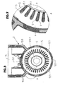
- the high-power electric motor generally designated 1 in FIGS. 1-9, consists of an outer motor housing 2 and of the stator 3 arranged concentrically about a housing longitudinal axis GL.
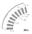
- the stator 3 is in turn essentially formed by a laminated core 4 and a winding 5 whose Conductor or winding sections in open to the axis GL and parallel to this axis extending grooves 6 is added.
- the grooves 6 are in this case formed so that they are open to the space enclosed by the stator 3 and serving to receive the rotor 8 space 7 each over a over the entire length of the sheet package 4 parallel to the axis GL extending slot 6.1 out of a Compared to the remaining area 6.2 each groove 6 has significantly reduced width.
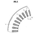
- the winding 5 forms at both ends of the laminated core 4 about this ends wegêt winding heads 5.1.
- the space 7 or the gap between the laminated core 4 and rotor 8 facing inner surface of the laminated core 4 is surrounded by a tubular wall portion 9 (can), which u.a. also seals all the grooves 6 at its slot 6.1 to the space 7 and rotor 8 back.
- a tubular wall portion 9 (can)
- can tubular wall portion 9
- At the two ends of the wall portion 9 is sealed in each case in an end 2.1 or 2.2 of the motor housing 2 via.
- the circular cylindrical wall section 9 is shaped so that it extends into the grooves 6 through slots 6.1 extending radially beyond the outer surface of this wall section 9, in such a way that the strip-like sections 9.1 the laminated core 4 in the area of Grooves 6 and their slots 6.1 engage behind a positive fit.
- the strip-like projections 9.1 are designed so that in each groove 6 between the local projection 9.1 and the winding 5, a gap or channel portion 10 remains, extending over the entire length of the laminated core 1 parallel to the axis GL and in an axis GL enclosing, outwardly closed annular space 11 opens.
- each such annular space 11 is formed and in which the local winding heads are 5.1 recorded.
- the annular spaces 11 are made slightly larger than the winding heads 5.1, so that in each annular space 11 around the winding heads 5.1 around a gap or channel portion 12 is formed, which is then in communication with all the channel sections 10.
- the cooling channel structure formed by the channel sections 10 and 12 is part of a coolant circuit, which has, among other things, a reservoir and a circulation pump for the liquid cooling medium and an external heat exchanger outside the engine.
- the cooling channel structure formed by the channel sections 10 and 12 is sealed, inter alia, tightly to the space 8 accommodating the rotor 8.
- the motor housing 2 consists in the illustrated embodiment substantially of plastic and is for example made in one piece with the wall portion 9 in the manner described in more detail below.
- the housing 2 contains a metal frame 13, which is executed filigree or multiple interrupted, u.a. with a cylinder-like section 13.1 enclosing the stator 3, with a section 13.3 reinforcing the housing end 2.1, which is at the same time designed as a bearing opening for receiving a bearing for the shaft of the rotor 8, and with an upper section 13.3, one with a not shown Cover lockable housing section 2.3 reinforced.
- the metal frame 13 is formed for screwing a lid, not shown, in which then the rotor 8 and its shaft are also mounted. Outwardly, the metal frame 13 is largely surrounded by the plastic material of the housing 2.
- Figures 4 - 9 illustrate the production of the electric motor 1.
- the stator 3 is made with the winding 5 and the end windings 5.1.
- each groove 6 is then partially removed again in a next method step, so that the slots 6.1 are exposed with their undercut formed by the subsequent broadening of each groove 6, as shown in FIG.
- each groove 6 thus remains a wax filling 15.1, which corresponds to the groove to be formed in this channel section 10 and this keeps clear and tightly closes the occupied by the conductors of the winding 5 space each groove to the outside.
- the partial removal of the wax filling 15 is effected, for example, mechanically with a suitable tool, e.g. with a multiple tool, with the same all grooves 6 or a larger number of multiple grooves for the partial removal of the wax filling 15 and to produce the remaining wax filling 15.1 are processed.
- the stator 3 thus provided with the wax fillings 15.1 and 16 is then inserted into the metal frame with the centering rings 17 made of plastic, so that after insertion of the stator 3 centered, i. is arranged with its longitudinal axis coaxially with the axis GL or with the axis of the prepared in the metal frame 13 bearing bore 13.2.1.
- the metal frame 13 is used with the stator 3 in a multi-part mold, in which the casing 2 and simultaneously also the wall section 9 are generated by sheathing the metal frame 13 with plastic or synthetic resin.
- the wall section 9 can also form the groove-like projections 9.1 that form-fittingly anchor it to the inner surface of the laminated core 4.
- the mold used inter alia, has a core that keeps the interior 7 as well as the already prepared in the metal frame 13 bearing bore 13.2.1 when casting the housing 2.
- the laminated core 4 is spaced on the extending between these centering rings length of the inner surface of the portion 13.1, so that this annulus during the casting of the housing 2 is filled by the plastic used and thereby the stator 3 mechanically fixed, but electrically isolated completely connected to the metal frame 13.
- the plastic used is preferably a synthetic resin, for example a two-component synthetic resin, which cures, for example, at a temperature well below the melting temperature of the material used for the wax fillings.
- the housing 2 After curing of the housing 2 and the wall portion 9 (can) forming plastic, the housing 2 is heated with the stator 3 in a suitable manner, for example in an oven to a temperature well above the melting point of the wax fillings 15.1 and 16 used wax lies. At this temperature, the liquefied wax is removed, via likewise formed from the wax inlet 18 at the winding heads 5.1 receiving spaces 11. At the same time is achieved by heating a further curing of the plastic, so that this or the housing 2 also at higher operating temperatures of the engine 1 are stable.
- the cooling channel structure through which the preferably liquid cooling medium can flow is finished on the stator 3.
- the assembly of the rotor 8, which is preferably equipped with permanent magnets, of the associated bearings and of the cover 2 terminating the housing 2 on the housing side 2.2 then takes place.
- the stator 3, namely the laminated core 4 and the winding 5 including the winding heads 5.1 are electrically from electrically conductive parts of the housing 2, namely the metal frame 13 and the bearings or bearing openings formed by this framework and through the wall portion 9 (can) also electrically opposite the rotor 8 separated;
- the cooling channels through which the cooling medium flows are designed such that in the region of the respective channel section 12, the cooling medium also surrounds the winding heads 5.1 completely flows around and also the heat energy accumulating here can be absorbed by the cooling medium.
- the interior space 17 of the upper housing section 2.3 communicates via the opening 18 with the cooling channel structure formed by the channel sections 10 and 12, ie. Also housed in the interior 17 power electronics is flowed around by the cooling medium.
- the training described has other advantages, namely:
- the grooves 6 are formed as cooling channels, so that a direct heat dissipation via the cooling medium takes place in the winding space of the stator 3; the wall portion 9 (split tube) is reliably held by the undercuts on the slots 6.1 positively engaging behind sections 9.1 on the inner surface of the laminated core 4; Even at a higher pressure of the cooling channels of the stator 3 flowing through the cooling medium, the risk of detachment of the wall portion 9 from the laminated core not.
- the housing 2 in the plastic casting method As a result of the production of the housing 2 in the plastic casting method, this can be produced in one piece in the form shown in FIG. 1, so that u.a. Complex seals and joining processes eliminated. Furthermore, due to the high manufacturing accuracy of the casting process can be dispensed with a post. With the metallic wire frame 13, a high mechanical strength and a high dimensional stability can be achieved. All voltage-carrying, in particular higher electrical voltage-carrying components of the power electronics are accommodated in the housing 2 or in the local, closable by a cover housing part 2.3, so that there are short electrical connections between these components and the winding 5. Furthermore, all components are flowed around by the cooling medium and therefore cooled.
- the entire power electronics accommodated in this inner space are accommodated in the housing 2 in an electrically insulated manner.
- an optimum contour for the areas of the cooling channel structure through which the cooling medium flows can be achieved, namely for effective heat transfer from the winding 5 to the cooling medium.
- the channels through which the cooling medium flows are as far as possible arbitrarily executable in their shape and / or position.
- the wax fillings 15 are processed by mechanical means to obtain the reduced wax fillings 15.1.
- Other methods are also conceivable, for example in the form that, instead of the wax fillings 15, the wax fillings 15.1 are already produced, specifically using a multi-part molding tool which has at least one tool part axially displaceable for demolding.
- FIG. 10 shows, as a further possible embodiment of the invention, a section through the stator 3a of a motor 1a.
- the stator 3a has no laminated core of a ferromagnetic material for forming the poles, but is made of a plastic which contains an electrically insulating but magnetically conductive filler, for example in the form of an oxide of a ferromagnetic material.
- the stator 3a consists of a plurality of coil carriers 20, which are made of an electrically and magnetically non-conductive material, for example made of plastic, and at equal angular intervals and with the same radial distance around the perpendicular to the plane of Figure 1 oriented longitudinal axis of the stator 3a are arranged.
- Each coil carrier 20 is formed in cross-section substantially V-shaped, with a web-like extension 20.1 on the rounded, closed and the axis of the stator 3a facing side.
- the plane of symmetry to which each coil support 20, including its web-like extension 20. 1, is mirror-symmetrical, is oriented radially to the stator axis.
- the sections or conductor winding 21 are added.
- each bobbin 20 is closed by a strip-like cover 22, which extends as well as the bobbin 20 over the entire length of the stator 3a.
- the bobbins 20 are e.g. connected by webs, not shown, to form an annular coil carrier assembly.
- the conductors of the winding 21 are first introduced into the coil carrier 20 arranged annularly around the axis of the stator 3a, specifically radially from the outside, so that the entire winding 21 can be produced in a particularly simple manner in an external winding process. In particular, this also makes it possible to automatically or mechanically create the complete winding 21.
- the sections of the winding 21 in each coil carrier 20 are potted so that it fills the cavities resulting from the introduction of the conductors, in particular also at the radially inner, closed region of each coil carrier 20 Spool carrier 20 are then sealed by the associated strip-shaped cover 22.
- the stator body 23 is molded from the plastic with the electrically insulating, magnetically conductive filler in the form that the individual coil carriers 20 are embedded in the stator body 23 and with the free ends of their webs 20.1 up to the inner surface of the stator 3a enclosing the opening 24 for the rotor, not shown, and thereby forming the magnetic gap between each two adjacent poles.
- a metal framework 25 is embedded radially offset outward in relation to the coil carriers 20.
- the coil carrier arrangement having the individual coil carriers 20 in such a way that the bars 20.1 projecting away from the V-shaped sections of the coil carriers 20 each extend into one common to the space 24 enclosing circular cylindrical wall portion 25 pass, which is also made of plastic, preferably in one piece with the coil carriers 20, and from the peripheral surface of the coil support 20 protrude radially.
- the wax is removed again by heating, so that form in each coil support 20 between the local conductors of the winding 21 and also on the radially inner closed region of the channels 26, which during operation of the motor 1a for cooling the Winding 21 and thus of the stator 3a of a preferably liquid, electrically insulating cooling medium, eg flowed through by a transformer oil.
- the electric motor 1 is particularly suitable and intended for high power
- the electric motor 1a represents a particularly inexpensive solution for a low-power motor.
- the cover 22 from wax so that, after the wax has melted out, the space previously occupied by the respective cover 22 also forms a channel through which the cooling medium flows.
Landscapes
- Engineering & Computer Science (AREA)
- Power Engineering (AREA)
- Manufacturing & Machinery (AREA)
- Motor Or Generator Frames (AREA)
- Manufacture Of Motors, Generators (AREA)
- Iron Core Of Rotating Electric Machines (AREA)
- Motor Or Generator Cooling System (AREA)
Applications Claiming Priority (1)
| Application Number | Priority Date | Filing Date | Title |
|---|---|---|---|
| DE102006029803A DE102006029803A1 (de) | 2006-06-27 | 2006-06-27 | Verfahren zum Herstellen einer elektrischen Maschine sowie elektrische Maschine, hergestellt nach diesem Verfahren |
Publications (1)
| Publication Number | Publication Date |
|---|---|
| EP1873887A2 true EP1873887A2 (fr) | 2008-01-02 |
Family
ID=38577563
Family Applications (1)
| Application Number | Title | Priority Date | Filing Date |
|---|---|---|---|
| EP07012117A Withdrawn EP1873887A2 (fr) | 2006-06-27 | 2007-06-21 | Procédé de fabrication d'une machine électrique et machine électrique fabriquée selon ce procédé |
Country Status (3)
| Country | Link |
|---|---|
| US (1) | US20080042498A1 (fr) |
| EP (1) | EP1873887A2 (fr) |
| DE (1) | DE102006062747A1 (fr) |
Cited By (1)
| Publication number | Priority date | Publication date | Assignee | Title |
|---|---|---|---|---|
| EP4243246A1 (fr) * | 2022-03-07 | 2023-09-13 | Dr. Ing. h.c. F. Porsche Aktiengesellschaft | Machine électrique pour un véhicule |
Families Citing this family (28)
| Publication number | Priority date | Publication date | Assignee | Title |
|---|---|---|---|---|
| US8674568B2 (en) * | 2011-01-21 | 2014-03-18 | Remy Technologies, L.L.C. | Machine with high voltage enclosure cover |
| DE102013201758A1 (de) * | 2013-02-04 | 2014-08-07 | Schaeffler Technologies Gmbh & Co. Kg | Elektromaschine mit einer Kühleinrichtung und Verfahren zu deren Herstellung |
| US20170012483A1 (en) * | 2015-07-09 | 2017-01-12 | Teofil Tony Toma | Electromagnetic Motor Patent |
| FR3041831B1 (fr) * | 2015-09-25 | 2019-04-19 | IFP Energies Nouvelles | Machine electrique tournante comportant un rotor et un stator pour le passage d'un fluide. |
| US10038351B2 (en) | 2016-03-17 | 2018-07-31 | Ford Global Technologies, Llc | Thermal management assembly for an electrified vehicle |
| US10097066B2 (en) | 2016-03-17 | 2018-10-09 | Ford Global Technologies, Llc | Electric machine for vehicle |
| US10008908B2 (en) | 2016-03-17 | 2018-06-26 | Ford Global Technologies, Llc | Electric machine for vehicle |
| US10008907B2 (en) | 2016-03-17 | 2018-06-26 | Ford Global Technologies, Llc | Over mold with integrated insert to enhance heat transfer from an electric machine end winding |
| US10086538B2 (en) | 2016-03-17 | 2018-10-02 | Ford Global Technologies, Llc | Thermal management assembly for an electrified vehicle |
| US10135319B2 (en) | 2016-03-17 | 2018-11-20 | Ford Global Technologies, Llc | Electric machine for vehicle |
| US10536055B2 (en) | 2016-03-17 | 2020-01-14 | Ford Global Technologies, Llc | Thermal management assembly for an electrified vehicle |
| DE102017208566A1 (de) * | 2017-05-19 | 2018-11-22 | Mahle International Gmbh | Elektrische Maschine, insbesondere für ein Fahrzeug |
| DE102017208556A1 (de) | 2017-05-19 | 2018-11-22 | Mahle International Gmbh | Elektrische Maschine, insbesondere für ein Fahrzeug |
| DE102017208546A1 (de) * | 2017-05-19 | 2018-11-22 | Mahle International Gmbh | Elektrische Maschine, insbesondere für ein Fahrzeug |
| DE102017208564A1 (de) * | 2017-05-19 | 2018-11-22 | Mahle International Gmbh | Elektrische Maschine, insbesondere für ein Fahrzeug |
| DE102017208550A1 (de) * | 2017-05-19 | 2018-11-22 | Mahle International Gmbh | Elektrische Maschine, insbesondere für ein Fahrzeug |
| FR3071369B1 (fr) * | 2017-09-18 | 2023-09-01 | Ifp Energies Now | Machine electrique comprenant un stator muni d'un manchon tubulaire interne |
| DE102017219867A1 (de) * | 2017-11-08 | 2019-05-09 | Magna powertrain gmbh & co kg | Stator mit integriertem Kühlmantel |
| US10892296B2 (en) | 2017-11-27 | 2021-01-12 | Seoul Viosys Co., Ltd. | Light emitting device having commonly connected LED sub-units |
| DE102017221808A1 (de) * | 2017-12-04 | 2019-06-06 | Mahle International Gmbh | Verfahren zum Herstellen eines Stators für eine elektrische Maschine |
| DE102017221803A1 (de) | 2017-12-04 | 2019-06-06 | Mahle International Gmbh | Elektrische Maschine, insbesondere für ein Fahrzeug |
| DE102017221801A1 (de) | 2017-12-04 | 2019-06-06 | Mahle International Gmbh | Verfahren zum Herstellen eines Stators für eine elektrische Maschine |
| DE102017221805A1 (de) | 2017-12-04 | 2019-06-06 | Mahle International Gmbh | Elektrische Maschine, insbesondere für ein Fahrzeug |
| CN107939345A (zh) * | 2017-12-19 | 2018-04-20 | 苏州泰铎电气有限公司 | 一种用于塔架式抽油机的永磁电机 |
| DE102018215889A1 (de) * | 2018-09-19 | 2020-03-19 | Robert Bosch Gmbh | Isoliervorrichtung mit Kühlmediumleitung |
| DE102018219816A1 (de) * | 2018-11-19 | 2020-05-20 | Mahle International Gmbh | Elektrische Maschine, insbesondere für ein Fahrzeug |
| DE102018219817A1 (de) * | 2018-11-19 | 2020-05-20 | Mahle International Gmbh | Elektrische Maschine, insbesondere für ein Fahrzeug |
| FR3093388B1 (fr) * | 2019-02-28 | 2021-03-12 | Nidec Psa Emotors | Machine électrique tournante ayant un refroidissement du stator amélioré |
Family Cites Families (5)
| Publication number | Priority date | Publication date | Assignee | Title |
|---|---|---|---|---|
| US5208503A (en) * | 1991-04-12 | 1993-05-04 | Hisey Bradner L | Energy-efficient ferromagnetic stator and core apparatus |
| US5864193A (en) * | 1993-10-15 | 1999-01-26 | Denso Corporation | Electric rotating machine having improved insulation for an armature coil |
| JP4923374B2 (ja) * | 2001-09-26 | 2012-04-25 | 日産自動車株式会社 | 回転電機のステータ構造 |
| US6930427B2 (en) * | 2002-09-30 | 2005-08-16 | Reliance Electric Technologies, Llc | Electric apparatus having a stator with insulated end laminations within the central opening of end plates |
| US20040145267A1 (en) * | 2003-01-29 | 2004-07-29 | Lowry Michael Jeffrey | Liners for stators and rotors of electric machines and methods of making |
-
2006
- 2006-06-27 DE DE102006062747A patent/DE102006062747A1/de not_active Withdrawn
-
2007
- 2007-06-21 EP EP07012117A patent/EP1873887A2/fr not_active Withdrawn
- 2007-06-27 US US11/819,503 patent/US20080042498A1/en not_active Abandoned
Cited By (1)
| Publication number | Priority date | Publication date | Assignee | Title |
|---|---|---|---|---|
| EP4243246A1 (fr) * | 2022-03-07 | 2023-09-13 | Dr. Ing. h.c. F. Porsche Aktiengesellschaft | Machine électrique pour un véhicule |
Also Published As
| Publication number | Publication date |
|---|---|
| DE102006062747A1 (de) | 2008-01-10 |
| US20080042498A1 (en) | 2008-02-21 |
Similar Documents
| Publication | Publication Date | Title |
|---|---|---|
| EP1873887A2 (fr) | Procédé de fabrication d'une machine électrique et machine électrique fabriquée selon ce procédé | |
| DE102006029803A1 (de) | Verfahren zum Herstellen einer elektrischen Maschine sowie elektrische Maschine, hergestellt nach diesem Verfahren | |
| EP2404365B1 (fr) | Moteur à rotor double | |
| WO2019154651A1 (fr) | Stator intérieur d'une machine à champ tournant comportant des groupes de dents de stator formés de dents directement adjacentes et d'un retour magnétique | |
| WO2014117773A2 (fr) | Machine électrique munie d'un dispositif de refroidissement et procédé de fabrication de ladite machine | |
| DE3879090T2 (de) | Verfahren zur Herstellung eines nutenlosen Ständers für einen elektrischen Motor und elektrischer Motor mit einem solchen Ständer. | |
| EP2523319B1 (fr) | Moteur linéaire cylindrique à faible pulsation de couple | |
| EP1780872B1 (fr) | Moteur électrique et procédé de fabrication de celui-ci | |
| DE2446501A1 (de) | Rotierende elektrische maschine und verfahren zur herstellung derselben | |
| WO2006066740A1 (fr) | Machine electrique | |
| DE102021113691A1 (de) | Stator einer elektrischen Antriebsmaschine und Verfahren zum Herstellen desselben | |
| WO2019110272A1 (fr) | Procédé de fabrication d'un stator pour une machine électrique | |
| WO2018192817A1 (fr) | Module de dent polaire pour une machine électrique, pièce active pourvue d'un module de dent polaire et machine électrique | |
| EP3989408A1 (fr) | Rotor pour une machine électrique, machine électrique pour un véhicule et procédé de fabrication d'un rotor pour une machine électrique | |
| DE102013223059A1 (de) | Elektrische Maschine mit vergossenem Wickelkopf | |
| WO2016050528A1 (fr) | Pièce active faisant office de rotor ou de stator, procédé de production d'une pièce active de ce type et moteur électrique | |
| WO2019121327A1 (fr) | Dent de stator et stator ayant une bonne isolation électrique et simultanément une très grande conductivité thermique pour augmenter la puissance de moteurs électriques | |
| EP1041697A2 (fr) | Machine à réluctance avec au moins deux pôles saillants, chacun avec bobinage d'excitation et procédé de fabrication du stator d'une telle machine | |
| EP2725688B1 (fr) | Rotor pour un moteur électrique | |
| EP2523321A1 (fr) | Moteur linéaire cylindrique doté d'un pied en tôle | |
| EP3408923A1 (fr) | Rotor, moteur électrique et procédé de fabrication d'un rotor | |
| DE2447155A1 (de) | Elektromotor und verfahren zu seiner herstellung | |
| DE102013101084A1 (de) | Drehfeldmaschine mit Außenläufer, insbesondere in modularer Bauweise | |
| DE102020129142B4 (de) | Läufer für eine rotierende elektrische Maschine | |
| DE102021109730A1 (de) | Elektrischer Kraftfahrzeug-Traktionsmotor |
Legal Events
| Date | Code | Title | Description |
|---|---|---|---|
| PUAI | Public reference made under article 153(3) epc to a published international application that has entered the european phase |
Free format text: ORIGINAL CODE: 0009012 |
|
| AK | Designated contracting states |
Kind code of ref document: A2 Designated state(s): AT BE BG CH CY CZ DE DK EE ES FI FR GB GR HU IE IS IT LI LT LU LV MC MT NL PL PT RO SE SI SK TR |
|
| AX | Request for extension of the european patent |
Extension state: AL BA HR MK YU |
|
| STAA | Information on the status of an ep patent application or granted ep patent |
Free format text: STATUS: THE APPLICATION IS DEEMED TO BE WITHDRAWN |
|
| 18D | Application deemed to be withdrawn |
Effective date: 20120103 |