EP4247129A1 - Circuit pattern, semi-finished base material for circuit substrate, metal-based circuit substrate, production method for circuit pattern, and production device for circuit pattern - Google Patents
Circuit pattern, semi-finished base material for circuit substrate, metal-based circuit substrate, production method for circuit pattern, and production device for circuit pattern Download PDFInfo
- Publication number
- EP4247129A1 EP4247129A1 EP21891604.7A EP21891604A EP4247129A1 EP 4247129 A1 EP4247129 A1 EP 4247129A1 EP 21891604 A EP21891604 A EP 21891604A EP 4247129 A1 EP4247129 A1 EP 4247129A1
- Authority
- EP
- European Patent Office
- Prior art keywords
- circuit
- circuit pattern
- pattern
- semi
- face
- Prior art date
- Legal status (The legal status is an assumption and is not a legal conclusion. Google has not performed a legal analysis and makes no representation as to the accuracy of the status listed.)
- Pending
Links
- 239000000758 substrate Substances 0.000 title claims abstract description 137
- 229910052751 metal Inorganic materials 0.000 title claims abstract description 97
- 239000002184 metal Substances 0.000 title claims abstract description 97
- 239000000463 material Substances 0.000 title claims description 101
- 238000004519 manufacturing process Methods 0.000 title claims description 46
- 239000004020 conductor Substances 0.000 claims abstract description 159
- 238000005530 etching Methods 0.000 claims description 122
- 230000015572 biosynthetic process Effects 0.000 claims description 60
- 230000007261 regionalization Effects 0.000 claims description 50
- 238000013508 migration Methods 0.000 abstract description 12
- 230000005012 migration Effects 0.000 abstract description 12
- 239000010410 layer Substances 0.000 description 122
- 238000010030 laminating Methods 0.000 description 24
- 239000007788 liquid Substances 0.000 description 19
- RYGMFSIKBFXOCR-UHFFFAOYSA-N Copper Chemical compound [Cu] RYGMFSIKBFXOCR-UHFFFAOYSA-N 0.000 description 18
- 229910052802 copper Inorganic materials 0.000 description 16
- 239000010949 copper Substances 0.000 description 16
- 238000003825 pressing Methods 0.000 description 12
- 150000002500 ions Chemical class 0.000 description 11
- 239000011888 foil Substances 0.000 description 10
- 239000011347 resin Substances 0.000 description 9
- 229920005989 resin Polymers 0.000 description 9
- 238000000034 method Methods 0.000 description 8
- 239000011256 inorganic filler Substances 0.000 description 7
- 229910003475 inorganic filler Inorganic materials 0.000 description 7
- 239000007921 spray Substances 0.000 description 7
- 238000005520 cutting process Methods 0.000 description 6
- XEEYBQQBJWHFJM-UHFFFAOYSA-N Iron Chemical compound [Fe] XEEYBQQBJWHFJM-UHFFFAOYSA-N 0.000 description 4
- 229910052782 aluminium Inorganic materials 0.000 description 4
- XAGFODPZIPBFFR-UHFFFAOYSA-N aluminium Chemical compound [Al] XAGFODPZIPBFFR-UHFFFAOYSA-N 0.000 description 4
- ORTQZVOHEJQUHG-UHFFFAOYSA-L copper(II) chloride Chemical compound Cl[Cu]Cl ORTQZVOHEJQUHG-UHFFFAOYSA-L 0.000 description 4
- XLJMAIOERFSOGZ-UHFFFAOYSA-M cyanate Chemical compound [O-]C#N XLJMAIOERFSOGZ-UHFFFAOYSA-M 0.000 description 4
- 230000000694 effects Effects 0.000 description 4
- 238000012546 transfer Methods 0.000 description 4
- 239000003795 chemical substances by application Substances 0.000 description 3
- 239000003822 epoxy resin Substances 0.000 description 3
- 239000011159 matrix material Substances 0.000 description 3
- 229920000647 polyepoxide Polymers 0.000 description 3
- OKTJSMMVPCPJKN-UHFFFAOYSA-N Carbon Chemical compound [C] OKTJSMMVPCPJKN-UHFFFAOYSA-N 0.000 description 2
- 229910021578 Iron(III) chloride Inorganic materials 0.000 description 2
- VYPSYNLAJGMNEJ-UHFFFAOYSA-N Silicium dioxide Chemical compound O=[Si]=O VYPSYNLAJGMNEJ-UHFFFAOYSA-N 0.000 description 2
- 239000012790 adhesive layer Substances 0.000 description 2
- IISBACLAFKSPIT-UHFFFAOYSA-N bisphenol A Chemical compound C=1C=C(O)C=CC=1C(C)(C)C1=CC=C(O)C=C1 IISBACLAFKSPIT-UHFFFAOYSA-N 0.000 description 2
- 229910052799 carbon Inorganic materials 0.000 description 2
- 239000011889 copper foil Substances 0.000 description 2
- 229960003280 cupric chloride Drugs 0.000 description 2
- 230000001747 exhibiting effect Effects 0.000 description 2
- 230000005484 gravity Effects 0.000 description 2
- 238000010438 heat treatment Methods 0.000 description 2
- 229910052742 iron Inorganic materials 0.000 description 2
- RBTARNINKXHZNM-UHFFFAOYSA-K iron trichloride Chemical compound Cl[Fe](Cl)Cl RBTARNINKXHZNM-UHFFFAOYSA-K 0.000 description 2
- 239000000203 mixture Substances 0.000 description 2
- 238000005507 spraying Methods 0.000 description 2
- 238000001039 wet etching Methods 0.000 description 2
- HCNHNBLSNVSJTJ-UHFFFAOYSA-N 1,1-Bis(4-hydroxyphenyl)ethane Chemical compound C=1C=C(O)C=CC=1C(C)C1=CC=C(O)C=C1 HCNHNBLSNVSJTJ-UHFFFAOYSA-N 0.000 description 1
- JYEUMXHLPRZUAT-UHFFFAOYSA-N 1,2,3-triazine Chemical compound C1=CN=NN=C1 JYEUMXHLPRZUAT-UHFFFAOYSA-N 0.000 description 1
- 229910000838 Al alloy Inorganic materials 0.000 description 1
- 229910052582 BN Inorganic materials 0.000 description 1
- PZNSFCLAULLKQX-UHFFFAOYSA-N Boron nitride Chemical compound N#B PZNSFCLAULLKQX-UHFFFAOYSA-N 0.000 description 1
- JOYRKODLDBILNP-UHFFFAOYSA-N Ethyl urethane Chemical compound CCOC(N)=O JOYRKODLDBILNP-UHFFFAOYSA-N 0.000 description 1
- 229910052581 Si3N4 Inorganic materials 0.000 description 1
- 239000000853 adhesive Substances 0.000 description 1
- 238000004026 adhesive bonding Methods 0.000 description 1
- 230000001070 adhesive effect Effects 0.000 description 1
- 229910045601 alloy Inorganic materials 0.000 description 1
- 239000000956 alloy Substances 0.000 description 1
- PNEYBMLMFCGWSK-UHFFFAOYSA-N aluminium oxide Inorganic materials [O-2].[O-2].[O-2].[Al+3].[Al+3] PNEYBMLMFCGWSK-UHFFFAOYSA-N 0.000 description 1
- -1 amin Substances 0.000 description 1
- 239000004841 bisphenol A epoxy resin Substances 0.000 description 1
- 239000004842 bisphenol F epoxy resin Substances 0.000 description 1
- 230000003197 catalytic effect Effects 0.000 description 1
- 238000006243 chemical reaction Methods 0.000 description 1
- 239000002131 composite material Substances 0.000 description 1
- 150000001875 compounds Chemical class 0.000 description 1
- PMHQVHHXPFUNSP-UHFFFAOYSA-M copper(1+);methylsulfanylmethane;bromide Chemical compound Br[Cu].CSC PMHQVHHXPFUNSP-UHFFFAOYSA-M 0.000 description 1
- 239000007822 coupling agent Substances 0.000 description 1
- 239000002270 dispersing agent Substances 0.000 description 1
- 238000002474 experimental method Methods 0.000 description 1
- 238000009413 insulation Methods 0.000 description 1
- 239000000395 magnesium oxide Substances 0.000 description 1
- CPLXHLVBOLITMK-UHFFFAOYSA-N magnesium oxide Inorganic materials [Mg]=O CPLXHLVBOLITMK-UHFFFAOYSA-N 0.000 description 1
- AXZKOIWUVFPNLO-UHFFFAOYSA-N magnesium;oxygen(2-) Chemical compound [O-2].[Mg+2] AXZKOIWUVFPNLO-UHFFFAOYSA-N 0.000 description 1
- 229910052755 nonmetal Inorganic materials 0.000 description 1
- 229920003986 novolac Polymers 0.000 description 1
- 239000005011 phenolic resin Substances 0.000 description 1
- 230000000704 physical effect Effects 0.000 description 1
- 238000003672 processing method Methods 0.000 description 1
- 238000007665 sagging Methods 0.000 description 1
- 239000011265 semifinished product Substances 0.000 description 1
- 239000000377 silicon dioxide Substances 0.000 description 1
- HQVNEWCFYHHQES-UHFFFAOYSA-N silicon nitride Chemical compound N12[Si]34N5[Si]62N3[Si]51N64 HQVNEWCFYHHQES-UHFFFAOYSA-N 0.000 description 1
- 239000002356 single layer Substances 0.000 description 1
- 239000010935 stainless steel Substances 0.000 description 1
- 229910001220 stainless steel Inorganic materials 0.000 description 1
- 239000000126 substance Substances 0.000 description 1
Images


Classifications
-
- H—ELECTRICITY
- H05—ELECTRIC TECHNIQUES NOT OTHERWISE PROVIDED FOR
- H05K—PRINTED CIRCUITS; CASINGS OR CONSTRUCTIONAL DETAILS OF ELECTRIC APPARATUS; MANUFACTURE OF ASSEMBLAGES OF ELECTRICAL COMPONENTS
- H05K1/00—Printed circuits
- H05K1/02—Details
- H05K1/0213—Electrical arrangements not otherwise provided for
- H05K1/0263—High current adaptations, e.g. printed high current conductors or using auxiliary non-printed means; Fine and coarse circuit patterns on one circuit board
- H05K1/0265—High current adaptations, e.g. printed high current conductors or using auxiliary non-printed means; Fine and coarse circuit patterns on one circuit board characterized by the lay-out of or details of the printed conductors, e.g. reinforced conductors, redundant conductors, conductors having different cross-sections
-
- H—ELECTRICITY
- H05—ELECTRIC TECHNIQUES NOT OTHERWISE PROVIDED FOR
- H05K—PRINTED CIRCUITS; CASINGS OR CONSTRUCTIONAL DETAILS OF ELECTRIC APPARATUS; MANUFACTURE OF ASSEMBLAGES OF ELECTRICAL COMPONENTS
- H05K1/00—Printed circuits
- H05K1/02—Details
- H05K1/03—Use of materials for the substrate
- H05K1/05—Insulated conductive substrates, e.g. insulated metal substrate
- H05K1/056—Insulated conductive substrates, e.g. insulated metal substrate the metal substrate being covered by an organic insulating layer
-
- H—ELECTRICITY
- H05—ELECTRIC TECHNIQUES NOT OTHERWISE PROVIDED FOR
- H05K—PRINTED CIRCUITS; CASINGS OR CONSTRUCTIONAL DETAILS OF ELECTRIC APPARATUS; MANUFACTURE OF ASSEMBLAGES OF ELECTRICAL COMPONENTS
- H05K3/00—Apparatus or processes for manufacturing printed circuits
- H05K3/10—Apparatus or processes for manufacturing printed circuits in which conductive material is applied to the insulating support in such a manner as to form the desired conductive pattern
- H05K3/20—Apparatus or processes for manufacturing printed circuits in which conductive material is applied to the insulating support in such a manner as to form the desired conductive pattern by affixing prefabricated conductor pattern
-
- H—ELECTRICITY
- H05—ELECTRIC TECHNIQUES NOT OTHERWISE PROVIDED FOR
- H05K—PRINTED CIRCUITS; CASINGS OR CONSTRUCTIONAL DETAILS OF ELECTRIC APPARATUS; MANUFACTURE OF ASSEMBLAGES OF ELECTRICAL COMPONENTS
- H05K2201/00—Indexing scheme relating to printed circuits covered by H05K1/00
- H05K2201/03—Conductive materials
- H05K2201/0332—Structure of the conductor
- H05K2201/0364—Conductor shape
- H05K2201/0367—Metallic bump or raised conductor not used as solder bump
-
- H—ELECTRICITY
- H05—ELECTRIC TECHNIQUES NOT OTHERWISE PROVIDED FOR
- H05K—PRINTED CIRCUITS; CASINGS OR CONSTRUCTIONAL DETAILS OF ELECTRIC APPARATUS; MANUFACTURE OF ASSEMBLAGES OF ELECTRICAL COMPONENTS
- H05K2203/00—Indexing scheme relating to apparatus or processes for manufacturing printed circuits covered by H05K3/00
- H05K2203/03—Metal processing
- H05K2203/0369—Etching selective parts of a metal substrate through part of its thickness, e.g. using etch resist
-
- H—ELECTRICITY
- H05—ELECTRIC TECHNIQUES NOT OTHERWISE PROVIDED FOR
- H05K—PRINTED CIRCUITS; CASINGS OR CONSTRUCTIONAL DETAILS OF ELECTRIC APPARATUS; MANUFACTURE OF ASSEMBLAGES OF ELECTRICAL COMPONENTS
- H05K2203/00—Indexing scheme relating to apparatus or processes for manufacturing printed circuits covered by H05K3/00
- H05K2203/14—Related to the order of processing steps
- H05K2203/1476—Same or similar kind of process performed in phases, e.g. coarse patterning followed by fine patterning
Definitions
- the present invention relates to a circuit pattern, a semi-finished base material for a circuit substrate, a metal-based circuit substrate, a production method for a circuit pattern, and a production device for a circuit pattern.
- a circuit pattern 103 of this printed wiring board 101 is formed by single-side etching performing etching to a metal foil only from an obverse face of an insulating substrate 105.
- a cross section of an individual circuit conductors 103a of the finished circuit pattern 103 is formed into a trapezoidal shape.
- a printed wiring substrate described in Patent document 1 is formed by improved process of single-side etching.
- the printed wiring substrate is improved with a width at a bottom portion more than a width at a top portion in a cross section of a circuit conductor composing a circuit pattern.
- the sectional shape of the circuit conductor is, however, formed into the substantial reverse trapezoidal shape by the single-side etching, the substantial conical shape or the substantial drum shape. It restricts increase in a sectional area of the circuit conductor to be limited on application to large current.
- a circuit pattern 103 of the printed wiring board 101 is formed by double-side etching performing etching at both an obverse and a reverse of a metal foil.
- a film-like protection material or the like is adhered to one side face of a single body of the metal foil being material, first.
- a patterned resist is formed and a first side etching is conducted.
- a parts corresponding to the circuit pattern 103 is formed up to and intermediate portion in a layer direction on the other side face of the metal foil by the first side etching.
- the other side face of the metal foil is adhered at the other face of the part corresponding to the circuit pattern 103 on an obverse face an insulating substrate 105 with pressing and heating.
- a patterned resist is formed on the one side face of the metal foil and a second side etching is conducted from the one side face.
- the part corresponding to the circuit pattern 103 is formed up to the intermediate portion in the layer direction on the one side face of the metal foil by the second side etching.
- the printed wiring board 101 is completed to have the circuit pattern 103 of the cross section illustrated in FIG. 21 on the insulating substrate 105.
- the circuit pattern 103 is formed so as to have the thickness of the metal foil thinner than the actual thickness through the double-side etching. Further, the cross section of the individual circuit conductor 103a composing the circuit pattern 103 is a swelled shape in a crossing direction (layer-crossing direction) to the layer direction at the intermediate portion in the layer direction. A sectional area of the circuit conductor 103a is, therefore, increased to be easily applied to current increase.
- the intermediate portion 103ab in the layer direction of the individual circuit conductor 103a of the circuit pattern 103 is a sharply pointed swelled shape along the obverse face of the insulating substrate 105.
- the sectional shape of the individual circuit conductor 103a is, therefore, a substantial trapezoidal shape with a bottom portion being the pointed intermediate portion 103ab on the obverse face of the insulating substrate 105. This results in remaining the problem to tend to cause short circuit between adjacent circuit conductors 103a and ion migration on the insulating substrate 105 similar to the circuit pattern 103 of FIG. 20 .
- a problem to be solved is that, in the case of the swelled shape in the layer-crossing direction at the intermediate portion in the layer direction, the sectional shape of the individual circuit conductor is the substantial trapezoidal shape with the bottom portion being the sharply pointed intermediate portion in the layer-crossing direction on the obverse face of the insulating substrate, and this results in remaining the problem to tend to cause short circuit and ion migration between adjacent circuit conductors to limit on tight arrangement of the circuit pattern.
- a circuit pattern according to the present invention is a circuit pattern comprising a circuit conductor to be layered on a metal substrate through an insulating layer, comprising an intermediate portion in a layer direction having a swelled shape in a layer-crossing direction in a cross section of the circuit conductor, wherein the swelled shape is formed by a gentle face in the layer direction.
- a semi-finished base material for a circuit substrate according to the present invention is that the circuit pattern is layered on a protection sheet.
- a metal-based circuit substrate according to the present invention is a metal-based circuit substrate in which a circuit pattern comprising a circuit conductor is layered on an insulating layer layered on a metal substrate, comprising an intermediate portion in a layer direction having a swelled shape in a layer-crossing direction relative to at least a portion located on an obverse face of the insulating layer in a cross section of the circuit conductor.
- a production method for a circuit pattern comprises a pattern formation step performing double-side etching to a material plate to form a semi-finished circuit pattern in which portions corresponding to individual circuit conductors composing a circuit pattern are connected through relatively thin connection portions, and a circuit formation step performing single-side etching to the connection portions from one side face of the semi-finished circuit pattern to form a circuit pattern in which intermediate portions of the circuit conductors in a cross section in a layer direction are formed into a swelled shape and the swelled shape is formed with a gentle face in the layer direction.
- a production device for a circuit pattern comprises a pattern formation device performing double-side etching to a material plate to form a semi-finished circuit pattern in which portions corresponding to individual circuit conductors composing a circuit pattern are connected through relatively thin connection portions, and a circuit formation device performing single-side etching to the connection portions from one side face of the semi-finished circuit pattern to form the circuit pattern in which intermediate portions of the circuit conductors in a cross section in a layer direction are formed into a swelled shape and the swelled shape is formed with a gentle face in the layer direction.
- the circuit pattern according to the present invention increases a sectional area of the circuit conductor according to the swelled shape of the intermediate portion, so that it is easily applied to current increase and it is advantageous for large current. Since the swelled shape is formed with the gentle face in the layer direction, short circuit at this portion relative to an adjacent circuit conductor is suppressed.
- the semi-finished base material for a circuit substrate according to the present invention layers the circuit pattern on the protection sheet, thereby keeping the circuit pattern having the swelled shape in stock.
- the metal-based circuit substrate according to the present invention is easily applied to current increase and is advantageous for large current. Further, it suppresses generation of ion migration between adjacent circuit conductors, thereby allowing the circuit pattern to be tightly arranged.
- the production method for a circuit pattern according to the present invention produces a circuit pattern to be easily applied to current increase and be advantageous for large current. Further, it allows the circuit pattern to be more tightly arranged according to suppressing short circuit and generation of ion migration between adjacent circuit conductors.
- the production device for a circuit pattern according to the present invention realizes the production method for a circuit pattern.
- the present invention accomplishes an object to be easily applied to current increase, be hard to generate short circuit or ion migration between adjacent circuit conductors and allow a circuit pattern to be tightly arranged as follows.
- a circuit pattern comprising a circuit conductor to be layered on a metal substrate through an insulating layer, comprises an intermediate portion in a layer direction having a swelled shape in a layer-crossing direction in a cross section of the circuit conductor, the swelled shape being formed by a gentle face in the layer direction.
- the layer direction means a layering direction or a thickness direction of the circuit conductor, and the layer-crossing direction is a crossing direction relative to the layer direction.
- the swelled shape of the intermediate portion in the layer direction in the cross section of the circuit conductor is formed circumferentially entirely on circumferential side faces in a circumferential direction of the circumferential side faces of the circuit conductor, but it may be partially formed.
- the intermediate portion in the layer direction means an arbitrary position between upper and lower faces of the circuit conductor in the layer direction.
- the gentle face in the layer direction of the circuit conductor means that it has no sharp point in the layer-crossing direction, and is a convex surface in the layer-crossing direction for example.
- the gentle face is, however, enough not to be sharply pointed in the layer-crossing direction, and need not be a curved surface. Namely, the gentle face may be a sagging convex surface, a deformed convex surface or the like.
- the swelled shape of the intermediate portion in the layer direction in the cross section of the circuit conductor is formed using double-side etching or single-side etching by means of wet etching, but any processing methods may be employed as long as the same shape is allowed to be formed.
- a width of a lower face contacting the insulating layer is wider than a width of an upper face in the cross section in the layer direction, or the width of the lower face contacting the insulating layer is narrower than the width of the upper face in the cross section in the layer direction.
- the circuit conductor may have the equivalent widths of the upper and the lower faces.
- a circuit pattern of a semi-finished base material for a circuit substrate may be configured to be layered on a protection sheet.
- the protection sheet one used for the etching may be used as it is.
- a protection sheet different from the protection sheet used for the etching may be, however, used.
- a size of the protection sheet is preferably in accordance with the circuit pattern.
- the protection sheet preferably has flexibility, but may be a rigid one.
- the circuit pattern of the semi-finished base material for a circuit substrate has a thickness more than 0.8mm.
- the circuit pattern is a pattern having a thickness according to needs for large current.
- the thickness of the circuit pattern may be, however, variously selected according to current specifications. Namely, the circuit pattern should be easily applied to current increase by means of the swelled shape in the cross section of the circuit conductor in comparison with a case that a cross section of a circuit conductor has no swelled shape.
- An upper limit and a lower limit of the thickness of the circuit pattern is in a range of common general knowledge for the circuit pattern.
- the circuit pattern may be formed of a copper foil, a rolled copper plate, an aluminum plate or the like.
- a metal-based circuit substrate is a metal-based circuit substrate in which a circuit pattern comprising a circuit conductor is layered on an obverse face of an insulating layer layered on a metal substrate, comprises an intermediate portion in a layer direction having a swelled shape in a layer-crossing direction relative to at least a portion located on an obverse face of the insulating layer in a cross section of the circuit conductor.
- Layering the circuit pattern comprising the circuit conductor on the obverse face of the insulating layer is a condition that the lower face of the circuit conductor is in contact with the obverse face of the insulating layer or is slightly embedded therein.
- the swelled shape includes a sharply pointed shape in the layer-crossing direction. The swelled shape may be formed by the gentle face in the layer direction.
- the circumferential side faces of the circuit conductor may be molded with resin on the insulating layer.
- a thickness and a planar shape of the metal substrate may be set according to specifications of the meta-based circuit substrate.
- a production method for a circuit pattern according to the present invention comprises a pattern formation step and a circuit formation step.
- the pattern formation step performs double-side etching to a material plate to form a semi-finished circuit pattern in which portions corresponding to individual circuit conductors composing a circuit pattern are connected through relatively thin connection portions.
- the circuit formation step performing single-side etching to the connection portions from one side face of the semi-finished circuit pattern to form a circuit pattern in which intermediate portions of the circuit conductors in a cross section in a layer direction are formed into a swelled shape and the swelled shape is formed with a gentle face in the layer direction.
- the etching to both sides of the material plate may be any one of simultaneously performing the etching to the both sides or performing the etching each side separately.
- the portions corresponding to the circuit conductors means portions corresponding to the circuit conductors of the metal-based circuit substrate, are connected with each other by the connection portions, and semi-finished products of the circuit conductors.
- the thin connection portion may be formed at an arbitrary position in the intermediate portion in the layer direction of the circuit conductor.
- connection portion means that the connection portion is thin relatively to the circuit conductor.
- the semi-finished circuit pattern is a semi-finished condition as the circuit pattern, in which an outline of the circuit pattern is formed by the double-side etching to the material plate and portions corresponding to the circuit conductors of the circuit pattern are connected with each other by the connection portions.
- the semi-finished circuit pattern is the result of the double-side etching to the material plate.
- the one side face of the semi-finished circuit pattern is any one of an obverse and a reverse of the semi-finished circuit pattern, and a selected face is the one side face and another face relative to this one side face is the other face.
- the production method for a circuit pattern may include a step of layering the produced circuit pattern on the metal substrate through the insulating layer in addition to the pattern formation step and the circuit formation step.
- the pattern formation step forms the semi-finished circuit pattern being circumferentially provided with a tongue portion on an outermost circumference of a portion of the semi-finished circuit pattern corresponding to the circuit pattern, the tongue portion having a shape corresponding to the connection portions, and the circuit formation step performs the single-side etching to the connection portions and the tongue portion to form the aforementioned swelled shape.
- the portion corresponding to the circuit pattern is a portion corresponding to the circuit pattern of the metal-based circuit substrate, and is configured by a combination of the portions corresponding to the individual circuit conductors connected together through the connection portions.
- the tongue portion having the shape corresponding to the connection portions means is a shape removable together with the connection portions by the single-side etching, dimensions in thickness and width of which are substantially the same as those of the connection portions for example.
- the circuit formation step includes a sheet-layering step that forms a resist pattern on the one side face of the semi-finished circuit pattern to expose the connection portions outside or expose the connection portions and the tongue portion outside and layers a protection sheet on the other side face of the semi-finished circuit pattern, and the circuit formation step performs the single-side etching from the one side face through the resist pattern.
- the circuit formation step removes the resist pattern after the single-side etching to obtain the semi-finished base material for a circuit substrate having the circuit pattern layered on the protection sheet.
- a production device for a circuit pattern comprises a pattern formation device and a circuit formation device.
- the pattern formation device performing double-side etching to a material plate to form a semi-finished circuit pattern in which portions corresponding to individual circuit conductors composing a circuit pattern are connected with each other through relatively thin connection portions.
- the circuit formation device performing single-side etching to the connection portions from one side face of the semi-finished circuit pattern to form the circuit pattern in which intermediate portions of the circuit conductors in a cross section in a layer direction are formed into a swelled shape and the swelled shape is formed with a gentle face in the layer direction.
- the production device for a circuit pattern comprises a layering device that forms a resist pattern on the one side face of the semi-finished circuit pattern to and layers a protection sheet on the other side face of the semi-finished circuit pattern, and the circuit formation device performs the single-side etching from the one side face through the resist pattern.
- the circuit formation device removes the resist pattern after the single-side etching to form the semi-finished base material for a circuit substrate having the circuit pattern layered on the protection sheet.
- FIG. 1(A) is a schematic sectional view of a metal-based circuit substrate in which swelled shapes are located closer to lower portions relatively to vertical centers in a layer direction of circuit conductors
- FIG. 1(B) is a schematic sectional view of a metal-based circuit substrate in which swelled shapes are located closer to upper portions relatively to vertical centers in the layer direction of circuit conductors.
- the layer direction means a layering direction of the metal-based circuit substrate.
- a layer-crossing direction means a planar direction of the metal-based circuit substrate.
- An upside means an upside in a direction of gravity when the metal-based circuit substrate is horizontally placed.
- a downside means a downside in the direction of gravity when the metal-based circuit substrate is horizontally placed.
- the metal-based circuit substrate 1 of FIGs. 1 is provided with a thick circuit pattern 3 according to needs for large current.
- the metal-based circuit substrates 1 of FIGs. 1(A) and (B) have basically the same structure, although the metal-based circuit substrates are different from each other in swelled shapes located closer to lower portions and located closer to upper portions relatively to vertical centers. Accordingly, the structure of the metal-based circuit substrate 1 is explained mainly using FIG. 1(A) , and the metal-based circuit substrate 1 of FIG. 1(B) and a cross section of the circuit conductors of FIG. 2 are referred if needed.
- the metal-based circuit substrate 1 is produced using to a semi-finished base material for a circuit substrate be explained later.
- the metal-based circuit substrate 1 is that the circuit pattern 3 is layered on a metal substrate 5 through an insulating layer 7.
- the circuit pattern 3 is formed of, for example, copper, and is formed of copper material for a circuit having a thickness of 3.0mm more than 0.8mm applicable to large current according to the present embodiment.
- the circuit pattern 3 is provided with a plurality of circuit conductors 3a electrically isolated. A structure of the plurality of circuit conductors 3a is formed according to required characteristics of the circuit pattern 3.
- a thickness of the circuit conductor 3a in the layer direction is selected in a range of 0.8-3.0mm.
- the thickness of the circuit conductor 3a in the layer direction may be, however, selected outside the range according to specifications of the metal-based circuit substrate 1.
- an intermediate portion in the layer direction is a swelled shape in the layer-crossing direction relative to at least a lower face 3a that is a portion located on the insulating layer 7.
- the intermediate portion in the layer direction is the swelled shape in the layer-crossing direction relative to an upper and the lower faces 3c and 3d.
- the swelled shape is formed by a gentle face 3b in the layer direction.
- the gentle face 3b in the layer direction is a convex surface.
- Each circuit conductor 3a has a shape in which the similar sectional shape is continuous in the circumferential direction.
- the intermediate portion of the circuit conductor 3a in the layer direction is a position of the circuit conductor 3a between the upper and the lower faces 3c and 3d in the layer direction.
- the face 3b of the swelled shape of FIG. 1(A) is slightly closer to the lower face 3d relatively to the vertical center of the circuit conductor 3a.
- the face 3b of the swelled shape of the circuit conductor 3a of FIG. 1(B) is slightly closer to the upper face 3c relatively to the vertical center of the circuit conductor 3a.
- the gentle face 3b in the layer direction is continuous in the layer direction with no sharply pointed portions (sharp point) in the layer-crossing direction or no angled portions.
- the convex surface of the face 3b is gradually continuous in an arc shape.
- An upside and a downside faces 3e and 3f relative to the face 3b of the swelled shape are inclined faces being substantially straight and continuous to the face 3b. It should be noted that the faces 3e and 3f may be formed in concave faces as illustrated in FIG. 4 to be explained later.
- the lower face 3d of the circuit conductor 3a illustrated in FIG. 1(A) has a width wider than of the upper face 3c.
- the width of the upper face 3c is formed wider than the width of the lower face 3d contrary to the circuit conductor 3a of FIG. 1(A) .
- a distance spanning between the faces 3b of the swelled shapes of the circuit conductors 3a is set to about 2mm, and a distance between the lower faces 3d is about 2.1mm.
- a distance between the lower faces 3d is about 2.2mm.
- a distance between the circuit conductors 103a on the obverse face of the insulating layer 105 is 2mm and is narrower than of the metal-based circuit substrates 1 of FIGs. 1(A) and (B) .
- the insulating layer 7 functions to electrically insulate the circuit pattern 3 from the metal substrate 5 and additionally functions as an adhesive bonding them together. Resin is, therefore, used generally for the insulating layer 7.
- a thickness of the insulating layer is set to 60-150 ⁇ m.
- the insulating layer 7 needs for high heat resistance against high heat buildup of elements mounted on the circuit pattern 3 and for high heat transference to transfer that heat to the metal substrate 5.
- the insulating layer 7 additionally includes inorganic fillers.
- epoxy resin such as bisphenol A epoxy resin, bisphenol F epoxy resin, or triazine type epoxy resin
- cyanate resin such as bisphenol E cyanate resin, bisphenol A cyanate resin, or novolak cyanate resin and the like are used singly or as a mixture of two or more kinds thereof.
- a curing agent such as amin, or phenol resin is used along with the epoxy resin.
- the curing agent may be a mixture of two or more kinds of, for example, the homologous amin compounds.
- a catalytic agent may be added for curing.
- the inorganic fillers included in the insulating layer 7 are superior in electric insulation and has high heat conductivity.
- alumina, silica, aluminum nitride, boron nitride, silicon nitride, magnesium oxide and the like are enumerated, and selected one or two or more kinds of them are used as inorganic fillers.
- a filling rate of the inorganic fillers in the insulating layer 7 is appropriately set according to kinds of the inorganic fillers.
- the filling rate of the inorganic fillers 85vol% or less, preferably 30-85vol% based on a whole volume of the matrix resin included in the insulating layer 7.
- the insulating layer 7 may include, for example, coupling agents, dispersants and the like other than the aforementioned matrix resin and the inorganic fillers.
- a semi-cured insulating sheet may be used as the insulating layer 7.
- the metal substrate 5 is made of, for example, elementary metal or alloy. As material of the metal substrate 5, aluminum, iron, copper, aluminum alloy, or stainless steel may be used for example.
- the metal substrate 5 may further include non-metal such as carbon.
- the metal substrate 5 may includes carbon and aluminum composite. Further, the metal substrate 5 may have a single layer structure or a multi-layer structure.
- the metal substrate 5 has high heat conductivity.
- the copper material has the heat conductivity of 370-400W.m-1.k-1
- the aluminum material has the heat conductivity of 190-220 W ⁇ m-1 ⁇ k-1
- the iron material has the heat conductivity of 60-80 W ⁇ m-1 ⁇ k-1.
- the metal substrate 5 may have flexibility or no flexibility.
- a thickness of the metal substrate 5 is set within a range of, for example, 1.0-3.0mm.
- the metal-based circuit substrate 1 may be configured as a metal-based circuit substrate using a metal substrate having a heat sink shape.
- the swelled shape is formed by the face 3b that is gentle in the layer direction and is the convex surface in the layer-crossing direction at the intermediate portion of the circuit conductor 3a in the layer direction as mentioned above.
- a sectional area of the circuit conductor 3a is increased by the swelled shape of the intermediate portion of the circuit conductor 3a.
- the metal-based circuit substrate 1 is, therefore, easily applied to current increase and is advantageous for large current.
- circuit conductor 3a Since the swelled shape of the circuit conductor 3a is formed by the face 3b being gentle in the layer direction, short circuit at this portion relative to an adjacent circuit conductor 3a is suppressed.
- the width of the lower face 3d of the circuit conductor 3a layered on the insulating layer 7 is smaller than the width at the face 3b of the intermediate portion. It, therefore, suppresses generation of ion migration between the circuit conductors 3a on the insulating layer 7.
- the metal-based circuit substrate 1 allows the circuit pattern 3 to be tightly arranged.
- the circuit conductor 3a illustrated in FIG. 1(A) in which the width of the lower face 3d is wider than the width of the upper face 3c makes adhesive strength relative to the insulating layer 7 larger than the circuit conductor 3a illustrated in FIG. 1(B) .
- FIG. 2 is a perspective view of a semi-finished base material for a circuit substrate
- FIG. 3 is a plan view of the circuit pattern
- FIG. 4 is a partially enlarged sectional of the circuit conductor.
- the semi-finished base material W1 for a circuit substrate according to the embodiment of the present invention is formed by layering the circuit pattern 3 on a protection sheet 9.
- the semi-finished base material W1 is produced by a production method for a circuit pattern using double-side etching and single-side etching as explained later.
- the protection sheet 9 is a back protection film used as it is, the back protection film laminated, when the single-side etching is performed from one side face of the semi-finished circuit pattern, on the other side face of the semi-finished circuit pattern as explained later.
- circuit pattern 3 is generally as mentioned above, a typical sectional shape of the circuit pattern is as illustrated in FIG. 4 if the circuit pattern is produced by the double-side etching and the single-side etching of wet etching to the copper plate material. The production method using the double-side etching and the single-side etching will be explained later.
- the face 3b being the arc-shaped convex surface is formed at the center between the upper and the lower faces 3c and 3d of the circuit conductor 3a or slightly closer to the upper face 3c relatively to the center (t1-t2 ⁇ t2).
- the upside and the downside faces 3e and 3f relative to the face 3b having the swelled shape are formed into concave shapes.
- the face 3b and the faces 3e and 3f are smoothly continuous in the layer direction on the circumferential faces of the circuit conductor 3a.
- the face 3b is protruded from the upper and the lower faces 3c and 3d in the layer-crossing direction.
- the metal-based circuit substrate 1 is, therefore, produced using the circuit pattern 3 of the semi-finished base material W1 for a circuit substrate.
- FIG. 5 is a process chart illustrating the production method for a circuit pattern.
- FIG. 6 is a process chart illustrating a production method for a metal-based circuit substrate that is a subsequent process of the production method for a circuit pattern.
- the production method for a circuit pattern and the production method for a metal-based circuit substrate are realized as a sequential line according to the embodiment, these production methods may be realized as separated lines.
- the production method for a circuit pattern is provided with a pattern formation step S1-S5 and a circuit formation step S6-S10. Further, the circuit formation step S6-S10 includes a sheet-layering step S6-S8.
- the pattern formation step S1-S5 performs the double-side etching to a copper foil or a copper plate material as material plate. Accordingly, the semi-finished circuit pattern is formed, the semi-finished circuit pattern in which portions corresponding to the individual circuit conductors 3a composing the circuit pattern 3 are connected with each other through relatively thin connection portions (explained later).
- the circuit formation step S6-S10 performs the single-side etching to the connection portions and a tongue portion (explained later) on an outermost circumference of the circuit pattern from the one side face of the semi-finished circuit pattern (explained later). This obtains the circuit pattern 3 in which the intermediate portion of the circuit conductor 3a in the cross section in the layer direction is formed into the swelled shape and the swelled shape is formed with the gentle face 3b in the layer direction.
- a second-film-laminating step S6 as the sheet-layering step forms a resist pattern (explained later) on the one side face of the semi-finished circuit pattern to expose the connection portions and the tongue portion outside and layers the protection sheet (explained later) on the other side face of the semi-finished circuit pattern.
- the pattern formation step S1-S5 is performed by a pattern formation device (explained later).
- the circuit formation step S6-S10 is performed by a circuit formation device (explained later).
- the sheet-layering step S6-S8 is performed by a layering device (explained later).
- the single-side etching from the one side face is performed through the resist pattern.
- the circuit formation step S6-S10 removes the resist pattern after the single-side etching to obtain the semi-finished base material W1 for a circuit substrate having the circuit pattern 3 layered on the protection sheet.
- the semi-finished base material W1 for a circuit substrate is used for production of the metal-based circuit substrate 1 according to a substrate-layering step S11-S14.
- the semi-finished base material W1 for a circuit substrate may be isolated from the sequential production line and be kept in stock as it is.
- FIG. 7-FIG.11 are related to the pattern formation device realizing the pattern formation step S1-S5
- FIG. 12-FIG. 13 are related to the circuit formation device realizing the circuit formation step S6-S10.
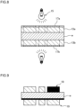
- FIG. 7 is a schematic sectional view illustrating a laminating situation of a first laminating device in the pattern formation device.
- FIG. 8 is a schematic sectional view illustrating an exposure situation at an exposure device in the pattern formation device.
- FIG. 9 is a schematic sectional view illustrating a developing situation at a developing device in the pattern formation device.
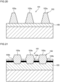
- FIG. 10 is a schematic sectional view illustrating a double-side etching situation at a double-side etching device in the pattern formation device.
- FIG. 11 is a schematic sectional view illustrating an alkali-peeling situation at an alkali-peeling device in the pattern formation device.
- FIG. 12 is a schematic sectional view illustrating a laminating situation at a second laminating device in the circuit formation device.
- FIG. 13 is a schematic sectional view illustrating a single-side etching situation at a single-side etching device in the circuit formation device.
- FIG. 14 is a perspective view illustrating a cutting image of the circuit pattern from the semi-finished base material for a circuit substrate.
- FIG. 15 is a schematic sectional view illustrating transference of the circuit pattern to a cushion material.
- FIG. 16 is a schematic sectional view of the cushion material to which the circuit pattern is transferred.
- FIG. 17 is a schematic sectional view illustrating vacuum heat pressing to transfer the circuit pattern to an insulating layer on the metal substrate.
- FIG. 18 is a schematic sectional view of the metal-based circuit substrate.
- FIG. 14 is a perspective view illustrating a cutting image of the circuit pattern from the semi-finished base material for a circuit substrate.
- FIG. 15 is a schematic sectional view illustrating transference of the circuit pattern to a cushion material.
- FIG. 16 is a schematic sectional view of the cushion material to which the circuit pattern is transferred.
- FIG. 17 is a schematic sectional view illustrating vacuum heat pressing to transfer the circuit pattern to an insulating layer on the metal substrate.
- FIG. 19(A) is a schematic sectional view illustrating the circuit pattern on the protection film cut off from the semi-finished base material for a circuit substrate.
- FIG. 19(B) is a schematic sectional view illustrating the circuit pattern transferred to the cushion material.
- FIG. 19(C) is a schematic sectional view illustrating the circuit pattern transferred to the insulating layer on the metal substrate.
- the step S1 is a first-film-laminating step of the pattern formation step. This step is realized by film laminating at the first laminating device 11 of FIG. 7 included in the pattern formation device.
- the copper plate material W as the material plate is cut in a substrate size in advance, and is fed between rolls 11a and 11b of the first laminating device 11 together with dry films 13a and 13b. With this step, the dry films 13a and 13b are stuck on an obverse and a reverse of the copper plate material W
- a dry film with a thickness of about 100 ⁇ m is used for the dry films 13a and 13b.
- a dry film with another thickness, for example, of about 40 ⁇ m may be, however, used for the dry films 13a and 13b.
- the step S2 is an exposure step of the pattern formation step. This step is realized by exposure at the exposure device 15 of FIG. 8 included in the pattern formation device. In this step, exposure films 17a and 17b are arranged on the dry films 13a and 13b on the obverse and the reverse of the copper plate material W in which the dry films 13a and 13b are stuck on the obverse and the reverse and exposure is performed.
- the step S3 is a developing step of the pattern formation step. This step is realized by developing at the developing device (not illustrated) included in the pattern formation device as illustrated in FIG. 9 . This step develops the dry films 13a and 13b on the obverse and the reverse of the copper plate material W exposed at the step S2 to remove uncured portion through the exposure. Portions of the copper plate material W exposed outside by the removing are portions not to be the circuit pattern. Namely, the remaining dry films 13a and 13b after the developing form a resist pattern 19 corresponding to the circuit pattern 3.
- the step S4 is a double-side etching step of the pattern formation step.
- This step is realized by the double-side etching at the double-side etching device 21 of FIG. 10 included in the pattern formation device.
- This step sprays etching liquid of ferric chloride from the obverse and the reverse of the copper plate material W using the double-side etching device 21 to perform the double-side etching.
- etching liquid cupric chloride liquid or alkali-etching liquid may be used.
- the double-side etching device 21 is just schematically illustrated in FIG. 10 .
- an appropriate known double-side etching machine may be employed.
- the double-side etching is performed by spraying at liquid temperature of 45°C, and spray pressure of 0.4Pa for etching time of about 30 minutes.
- a condition of the double-side etching such as the liquid temperature may be, however, variously altered according to the setting of the connection portions 23 and the tongue 23a.
- the tongue portion 23a is formed on an outermost circumference of a portion 3A corresponding to the circuit pattern composed of the portions 3aa corresponding to the circuit conductors 3a, the tongue portion having a shape corresponding to that of the connection portion 23.
- the tongue portion 23a is circumferentially shaped so as to entirely surround the portion 3A corresponding to the circuit pattern.
- a thickness, and a protruding dimension of the tongue portion 23a are sized equivalently with a thickness of the connection portion 23 and a dimension spanning between the circuit conductors 3a.
- the step S5 is an alkali-peeling step of the pattern formation step. This step is realized by the alkali-peeling at the alkali-peeling device (not illustrated) included in the pattern formation device as illustrated in FIG. 11 . This step removes the resist pattern 19 corresponding to the circuit pattern 3 using alkali-liquid after the developing, to form the semi-finished circuit pattern 25. In the semi-finished circuit pattern 25, the portions 3aa corresponding to the individual circuit conductors 3a composing the circuit pattern 3 are connected with each other by the relatively thin connection portions 23.
- the step S6 is the second-film-laminating step of the circuit formation step.
- the second-film-laminating step composes the sheet-layering step together with an exposure step of the step S7, and a developing step of the step S8, to form a resist pattern 31 as explained later.
- This step is realized by film laminating at a second- laminating device 27 of FIG. 12 included in the circuit formation device.
- the semi-finished circuit pattern 25 is fed between rolls 27a and 27b of the second-laminating device 27 together with a dry film 29 and a back protection film being the protection sheet 9.
- the dry film 29 is stuck on an obverse face of the semi-finished circuit pattern 25, and the back protection film being the protection sheet 9 is stuck on a reverse face of the same.
- the obverse and the reverse of the semi-finished circuit pattern 25 are arbitrary selected.
- a dry film having a thickness of about 100 ⁇ m is used.
- a dry film with another thickness, for example, of about 40 ⁇ m may be, however, used as the dry film 29.
- the step S7 is the exposure step of the circuit formation step
- the step S8 is the developing step of the circuit formation step.
- the steps S7 and S8 implement steps similar to the steps S2 and S3 of the pattern formation step.
- the steps S7 and S8 compose the sheet-layering step of the circuit formation step together with the step S6.
- the second-laminating device 27, the exposure device, and the developing device realizing the sheet-layering step compose the layering device.
- the dry film 29 remaining after the developing in the step S8 forms the resist pattern 31 to expose the connection portions 23 on the obverse face being the one side face of the semi-finished circuit pattern 25 so as to correspond to the circuit pattern.
- the protection sheet 9 being the back protection film is layered and stuck.
- the step S9 is a single-side etching of the circuit formation step.
- This step is realized by the single-side etching at the single-side etching device 33 of FIG. 13 included in the circuit formation device.
- This step sprays etching liquid of ferric chloride through the resist pattern 31 on the one side face using the single-side etching device 33 to perform the single-side etching.
- the single-side etching device 33 is just schematically illustrated in FIG. 13 .
- an appropriate known single-side etching machine may be employed as the single-side etching device 33.
- cupric chloride liquid or alkali-etching liquid may be used similar to the above.
- the single-side etching is performed by spraying at liquid temperature of 45°C and spray pressure of 0.4Pa for etching time of about 5 minutes.
- a condition of the double-side etching such as the liquid temperature may be, however, variously altered according to thicknesses and positions of the connection portions 23 and the tongue 23a in the layer direction. With the single-side etching, the connection portions 23 and the tongue 23a are etched and removed.
- connection portions 23 and the tongue portion 23a are not completely removed and are remained so as to make the circumferential side faces of the circuit conductors 3a be the swelled shape.
- the etching liquid spreads the swelled shape entirely in the layer direction according to progress of the etching.
- the surface of the swelled shape is formed as the face 3b being the arc-shaped convex surface 3b as illustrated in FIG. 4 .
- a form of the convex surface of the face 3b may be adjusted according to the setting of the liquid temperature, the spray pressure and the etching time.
- the setting of a position of the face 3b between the upper and the lower faces 3c and 3d, a size of the swelled shape, and the widths of the upper and the lower faces 3c and 3d may be adjusted by the setting of the vertical position and thicknesses of the connection portions 23 and the tongue portion 23a, and the liquid temperature, the spray pressure, and the etching time of the single-side etching.
- the step S10 is relates to a completing step of the circuit formation step.
- the completing step performs a step similar to the alkali-peeling step of the step S5.
- the resist pattern 31 is removed by alkali-peeling at an alkali-peeling device included in the circuit formation device after the single-side etching in the step S9. Consequently, the semi-finished base material W1 for a circuit substrate in FIG. 2 is obtained as the result.
- the circuit pattern 3 is stuck on the back protection film being the protection sheet 9.
- the metal-based circuit substrate 1 is completed through the substrate-layering step S11-S14 of FIG. 6 .
- the circuit pattern 3 is cut out one by one from the semi-finished base material W1 for a circuit substrate as illustrated in FIG. 14 , and the circuit pattern 3 is transferred at a bare face (obverse face) to the cushion material 35.
- the back protection film is detached and the circuit pattern 3 is stuck, in a side from which the protection film is detached, on the insulating layer 7 on the metal substrate 5.
- the cushion material 35 is detached, and the circuit pattern 3 is subjected to pressure heating process to complete the metal-based circuit substrate 1.
- the step S11 in FIG. 6 is a cutting step of the substrate-layering step. This step cuts off the lump circuit pattern 3 from the semi-finished base material W1 for a circuit substrate obtained as the above as illustrated in FIG. 14 . In this cutting-off, the protection sheet 9 is cut to cut off the lump circuit pattern 3 as well as the protection sheet.
- the step S12 is a transference step. This step orients the obverse face of the circuit pattern 3 toward the obverse face of the cushion material 35 as illustrated in FIG. 15 , and transfers the circuit pattern 3 to the cushion material 35 by pressing. At this time, mutual positions of the individual circuit conductors 3a of the circuit pattern 3 are accurately kept by the protection sheet 9.
- the cushion material 35 is made of urethane having a thickness of 3-5mm for example.
- the obverse face of the cushion material 35 is provided with an adhesive layer.
- the obverse face of the circuit pattern 3 is kept on the adhesive layer of the obverse face of the cushion material 35 with adhesion.
- Adhesion strength of the cushion material 35 is set higher than holding force based on the protection sheet 9 for the circuit pattern 3. The protection sheet 9 is, therefore, detached after the pressing, thereby transferring the circuit pattern 3 to the cushion material 35 as illustrated FIG. 16 .
- the step S13 is a vacuum heat pressing step. This step presses the circuit pattern 3 that is hold by the cushion material 35 to the insulating layer 7 on the metal substrate 5 by the vacuum heat pressing as illustrated in FIG. 17 .
- the cushion material 35 receives reaction force from each circuit conductor 3a and deforms at an adhering portion of each circuit conductor 3a, and the remaining portions other than the adhering portion of each circuit conductor 3a deform so as to reach the insulating layer 7. With the elasticity of the cushion material 35, each circuit conductor 3a is appropriately pressed on the uncured insulating layer 7 at the vacuum heat pressing.
- the thickness of the cushion material 35 is, therefore, set according to the thickness of the circuit conductor 3a to be pressed. Namely, the cushion material 35 is thick for a thick circuit conductor 3a and is thin for a thin circuit conductor 3a. The relationship between these thicknesses may be set in relation to the elasticity of the cushion material 35 through a pre-experiment.
- the step S14 is the completing step. This step detaches the cushion material 35 after curing the insulating layer 7. This completes the metal-based circuit substrate 1 of FIG. 18 .
- Relationships between the swelled shape and the processes of the steps S11-S14 is as illustrated in FIG. 19 .
- the lower face 3d of the individual circuit conductor 3a of the circuit pattern 3 is held by the protection sheet 9 cut out in the cutting step of the step S11, and the upper face 3c of the individual circuit conductor 3a is exposed outside.
- the face 3b having the swelled shape of the individual circuit conductor 3a is lower than the vertical center position of the circuit conductor 3a when the protection sheet 9 is positioned on the downside.
- the individual circuit conductor 3a of the circuit pattern 3 is reversed through the transferring step of the step S12, the upper face 3c of the individual circuit conductor 3a is held by the cushion material 35, and the lower face 3d of the individual circuit conductor 3a is exposed outside.
- the face 3b is higher than the vertical center position of the circuit conductor 3a when the cushion material 35 is positioned on the downside.
- the individual circuit conductor 3a is reversed again, and the lower face 3d is fixed to the insulating layer 7.
- the cushion material 35 is detached using a detaching roller (not illustrated) or the like after curing the insulating layer 7, thereby exposing the upper face 3c of each circuit conductor 3a outside.
- the face 3b of the swelled shape of the individual circuit conductor 3a is lower than the vertical center position of the circuit conductor 3a when the insulating layer 7 is position on the downside.
- the face 3b of the swelled shape of the individual circuit conductor 3a in the completed metal-based circuit substrate 1 may be higher than the vertical center position of the circuit conductor 3a when the insulating layer 7 is positioned on downside.
- the face 3b of the swelled shape of the individual circuit conductor 3a is higher than the vertical center position of the circuit conductor 3a when the protection sheet 9 is positioned on the downside according to the cutting step of the step S11.
- the face 3b in the transference step of the step S12 is lower than the vertical center position of the circuit conductor 3a when the cushion material 35 is positioned on the downside.
- the face 3b in the vacuum heat pressing step and the completing step of the steps S13 and S14 is higher than the vertical center position of the circuit conductor 3a when the insulating layer 7 is positioned on the downside.
- the cushion material 35 is used in the substrate-layering step of FIG. 6 , it may be omitted.
- the protection sheet 9 may be substituted for the cushion material as it is to perform the vacuum heat pressing step S13 after the cutting step S11.
- This protection sheet 9 may have chemical resistance against the etching liquid and physical properties with a thickness and elasticity equivalent to the cushion material 35 in the vacuum heat pressing step of the step S13.
- the circuit pattern 3 comprising the circuit conductor 3a to be layered on the metal substrate 5 through the insulating layer 7, comprises the intermediate portion in the layer direction having the swelled shape in the layer-crossing direction in the sectional shape of the circuit conductor 3a, the swelled shape being formed by the gentle face 3b that is the arc-shaped convex surface continuous in the layer direction.
- the volume of the circuit conductor 3a is, therefore, increased by the swelled shape of the face 3b.
- the arc-shaped convex surface surely increases the volume of the circuit conductor 3a without forming the swelled shape into a sharply pointed shape.
- the swelled shape is easily applied to current increase and is advantageous in large current.
- the swelled shape is formed by the face 3b gentle in the layer direction, short circuit is suppressed at the faces 3b between adjacent circuit conductors 3a.
- the arc-shaped convex surface surely suppresses short circuit between the circuit conductors 3a at the swelled shapes.
- the width of the lower face 3d of the circuit conductor 3a layered on the insulating layer 7 is made narrower than the width between the faces 3b at the intermediate portions while increasing the volume of the circuit conductor 3a.
- the width of the circuit conductor 3a is smaller at the portion of the lower face 3d to suppress short circuit between adjacent circuit conductors 3a and generation of ion migration.
- the width of the lower face 3d contacting the insulating layer 7 in the cross section in the layer direction is narrower than the width of the upper face 3c.
- the circuit pattern 3 is layered on the protection sheet 9 being the back protection film.
- the protection sheet 9 protects the back of the circuit pattern 3 from the etching liquid at the time of the single-side etching. Further, the protection sheet 9 allows the result to be handled as the semi-finished base material W1 for a circuit substrate in which the circuit pattern 3 is layered on the protection sheet 9 and facilitates to keep the semi-finished base material in stock.
- the circuit pattern 3 of the semi-finished base material W1 for a circuit substrate is formed of the copper plate material W with the thickness of 3.0mm more than 0.8mm. With the thickness of the circuit pattern 3, it is applicable to large current.
- the circuit pattern 3 is layered on the metal substrate 5 through the insulating layer 7. With the layering, it obtains the metal-based circuit substrate 1 having the circuit pattern 3 exhibiting the aforementioned effect.
- the production method for a circuit pattern comprises the pattern formation step S1-S5 performing the double-side etching to the copper plate material Wto form the semi-finished circuit pattern 25 in which the portions 3aa corresponding to the individual circuit conductors 3a composing the circuit pattern 3 are connected through the relatively thin connection portions 23, and the circuit formation step S6-S10 performing the single-side etching to the connection portions 23 from the one side face of the semi-finished circuit pattern 25 to form the circuit pattern 3 in which the intermediate portions of the circuit conductors 3a in the cross section in the layer direction is formed into the swelled shape and the swelled shape is formed with the face 3b gentle in the layer direction.
- the pattern formation step S1-S5 of the production method for a circuit pattern forms the semi-finished circuit pattern 25 by the double-side etching.
- the circuit formation step S6-S10 forms the circuit pattern 3 using the semi-finished circuit pattern 25.
- the pattern formation step S1-S5 circumferentially forms the tongue portion 23a on the outermost circumference of the portion 3A of the semi-finished circuit pattern 25 corresponding to the circuit pattern 3 together with the connection portions 23, the tongue portion having the shape corresponding to the connection portions.
- the intermediate portion of the circuit conductor 3a in the cross section in the layer direction is formed into the swelled shape and the swelled shape is formed with the face 3b gentle in the layer direction even on the outermost circumference of the circuit pattern 3.
- the circuit formation step S6-S10 includes the sheet-layering step S6-S8 that forms the resist pattern 31 on the one side face of the semi-finished circuit pattern 25 to expose the connection portions 23 and the tongue portion 23a outside and layers the protection sheet 9 on the other side face of the semi-finished circuit pattern 25, and the circuit formation step S6-S10 performs the single-side etching from the one side face through the resist pattern 31.
- the swelled shapes of the gentle faces 3b are formed on the circumferential faces of the circuit conductors 3a.
- the face 3b may be formed into the arc-shaped convex surface according to the setting of the liquid temperature, the spray pressure, and the etching time of the single-side etching.
- the circuit formation step S6-S10 removes the resist pattern 31 after the single-side etching to form the semi-finished base material W1 for a circuit substrate having the circuit pattern 3 layered on the protection sheet 9.
- the semi-finished base material W1 for a circuit substrate facilitates to be handled and kept in stock.
- the semi-finished base material W1 for a circuit substrate is used to produce the metal-based circuit substrate 1, thereby obtaining the metal-based circuit substrate 1 having the circuit pattern 3 exhibiting the aforementioned effect.
- the production device for a circuit pattern comprises the pattern formation device performing the double-side etching to the copper plate material Wto form the semi-finished circuit pattern 25 in which the portions 3aa corresponding to the individual circuit conductors 3a composing the circuit pattern 3 are connected through the relatively thin connection portions 23, and the circuit formation device performing the single-side etching to the connection portions 23 from the one side face of the semi-finished circuit pattern 25 to form the circuit pattern 3 in which the intermediate portions of the circuit conductors 3a in the cross section in the layer direction are formed into the swelled shape and the swelled shape is formed with the face 3b gentle in the layer direction.
- the production device for a circuit pattern realizes the production method for a circuit pattern, to obtain the circuit pattern 3 with the swelled shape formed with the gentle face 3b in the layer direction.
- the production device for a circuit pattern comprises the second laminating device 27 as the layering device that forms the resist pattern 31 on the one side face of the semi-finished circuit pattern 25 to expose the connection portions 23 outside and layers the protection sheet 9 on the other side face of the semi-finished circuit pattern 25, the exposure device, and the developing device, wherein the circuit formation device performs the single-side etching from the one side face through the resist pattern 31.
- the production device for a circuit pattern realizes the production method for a circuit pattern, and the circuit formation device obtaining the circuit pattern 3 with the swelled shape formed with the gentle face 3b removes the resist pattern 9 after the single-side etching to form the semi-finished base material W1 for a circuit substrate having the circuit pattern 3 layered on the protection sheet 9.
- the semi-finished base material W1 for a circuit substrate for the circuit pattern 3 with the swelled shape formed with the gentle face 3b in the layer direction is obtained.
Landscapes
- Engineering & Computer Science (AREA)
- Microelectronics & Electronic Packaging (AREA)
- Manufacturing & Machinery (AREA)
- Manufacturing Of Printed Circuit Boards (AREA)
- Insulated Metal Substrates For Printed Circuits (AREA)
Abstract
Description
- The present invention relates to a circuit pattern, a semi-finished base material for a circuit substrate, a metal-based circuit substrate, a production method for a circuit pattern, and a production device for a circuit pattern.
- Conventionally, there is one having a cross section illustrated in
FIG. 20 as a printed wiring board. Acircuit pattern 103 of this printedwiring board 101 is formed by single-side etching performing etching to a metal foil only from an obverse face of aninsulating substrate 105. - With the single-side etching, a cross section of an
individual circuit conductors 103a of the finishedcircuit pattern 103 is formed into a trapezoidal shape. Forming thecircuit pattern 103 with a tight arrangement, there is a problem to tend to cause disconnection at a top portion of thecircuit pattern 103, short circuit and ion migration betweenadjacent circuit conductors 103a at a bottom of the circuit pattern. - In contrast, a printed wiring substrate described in
Patent document 1 is formed by improved process of single-side etching. The printed wiring substrate is improved with a width at a bottom portion more than a width at a top portion in a cross section of a circuit conductor composing a circuit pattern. - In the printed wiring substrate described in
Patent document 1, the sectional shape of the circuit conductor is, however, formed into the substantial reverse trapezoidal shape by the single-side etching, the substantial conical shape or the substantial drum shape. It restricts increase in a sectional area of the circuit conductor to be limited on application to large current. - On the other hand, a printed
wiring board 101 with a cross section illustrated inFIG. 21 is proposed in Patent document 2. - A
circuit pattern 103 of the printedwiring board 101 is formed by double-side etching performing etching at both an obverse and a reverse of a metal foil. - In the double-side etching, a film-like protection material or the like is adhered to one side face of a single body of the metal foil being material, first.
- On the other side face of the metal foil, a patterned resist is formed and a first side etching is conducted. A parts corresponding to the
circuit pattern 103 is formed up to and intermediate portion in a layer direction on the other side face of the metal foil by the first side etching. - Next, the other side face of the metal foil is adhered at the other face of the part corresponding to the
circuit pattern 103 on an obverse face aninsulating substrate 105 with pressing and heating. - Further, a patterned resist is formed on the one side face of the metal foil and a second side etching is conducted from the one side face. The part corresponding to the
circuit pattern 103 is formed up to the intermediate portion in the layer direction on the one side face of the metal foil by the second side etching. - As a result, the printed
wiring board 101 is completed to have thecircuit pattern 103 of the cross section illustrated inFIG. 21 on theinsulating substrate 105. - According to the printed
wiring board 101, thecircuit pattern 103 is formed so as to have the thickness of the metal foil thinner than the actual thickness through the double-side etching. Further, the cross section of theindividual circuit conductor 103a composing thecircuit pattern 103 is a swelled shape in a crossing direction (layer-crossing direction) to the layer direction at the intermediate portion in the layer direction. A sectional area of thecircuit conductor 103a is, therefore, increased to be easily applied to current increase. - The simple both-side etching, however, performs etching from both the obverse and the reverse sides of the metal foil. Accordingly, the intermediate portion 103ab in the layer direction of the
individual circuit conductor 103a of thecircuit pattern 103 is a sharply pointed swelled shape along the obverse face of theinsulating substrate 105. - In the
circuit pattern 103 ofFIG. 21 , the sectional shape of theindividual circuit conductor 103a is, therefore, a substantial trapezoidal shape with a bottom portion being the pointed intermediate portion 103ab on the obverse face of theinsulating substrate 105. This results in remaining the problem to tend to cause short circuit betweenadjacent circuit conductors 103a and ion migration on theinsulating substrate 105 similar to thecircuit pattern 103 ofFIG. 20 . -
- PATENT DOCUMENT 1:
JP 2005-209920 A - PATENT DOCUMENT 2:
JP H10-178256 A - A problem to be solved is that, in the case of the swelled shape in the layer-crossing direction at the intermediate portion in the layer direction, the sectional shape of the individual circuit conductor is the substantial trapezoidal shape with the bottom portion being the sharply pointed intermediate portion in the layer-crossing direction on the obverse face of the insulating substrate, and this results in remaining the problem to tend to cause short circuit and ion migration between adjacent circuit conductors to limit on tight arrangement of the circuit pattern.
- A circuit pattern according to the present invention is a circuit pattern comprising a circuit conductor to be layered on a metal substrate through an insulating layer, comprising an intermediate portion in a layer direction having a swelled shape in a layer-crossing direction in a cross section of the circuit conductor, wherein the swelled shape is formed by a gentle face in the layer direction.
- A semi-finished base material for a circuit substrate according to the present invention is that the circuit pattern is layered on a protection sheet.
- A metal-based circuit substrate according to the present invention is a metal-based circuit substrate in which a circuit pattern comprising a circuit conductor is layered on an insulating layer layered on a metal substrate, comprising an intermediate portion in a layer direction having a swelled shape in a layer-crossing direction relative to at least a portion located on an obverse face of the insulating layer in a cross section of the circuit conductor.
- A production method for a circuit pattern according to the present invention, comprises a pattern formation step performing double-side etching to a material plate to form a semi-finished circuit pattern in which portions corresponding to individual circuit conductors composing a circuit pattern are connected through relatively thin connection portions, and a circuit formation step performing single-side etching to the connection portions from one side face of the semi-finished circuit pattern to form a circuit pattern in which intermediate portions of the circuit conductors in a cross section in a layer direction are formed into a swelled shape and the swelled shape is formed with a gentle face in the layer direction.
- A production device for a circuit pattern according to the present invention, comprises a pattern formation device performing double-side etching to a material plate to form a semi-finished circuit pattern in which portions corresponding to individual circuit conductors composing a circuit pattern are connected through relatively thin connection portions, and a circuit formation device performing single-side etching to the connection portions from one side face of the semi-finished circuit pattern to form the circuit pattern in which intermediate portions of the circuit conductors in a cross section in a layer direction are formed into a swelled shape and the swelled shape is formed with a gentle face in the layer direction.
- The circuit pattern according to the present invention increases a sectional area of the circuit conductor according to the swelled shape of the intermediate portion, so that it is easily applied to current increase and it is advantageous for large current. Since the swelled shape is formed with the gentle face in the layer direction, short circuit at this portion relative to an adjacent circuit conductor is suppressed.
- The semi-finished base material for a circuit substrate according to the present invention layers the circuit pattern on the protection sheet, thereby keeping the circuit pattern having the swelled shape in stock.
- The metal-based circuit substrate according to the present invention is easily applied to current increase and is advantageous for large current. Further, it suppresses generation of ion migration between adjacent circuit conductors, thereby allowing the circuit pattern to be tightly arranged.
- The production method for a circuit pattern according to the present invention produces a circuit pattern to be easily applied to current increase and be advantageous for large current. Further, it allows the circuit pattern to be more tightly arranged according to suppressing short circuit and generation of ion migration between adjacent circuit conductors.
- The production device for a circuit pattern according to the present invention realizes the production method for a circuit pattern.
-
- [
FIG. 1] FIG. 1(A) is a schematic sectional view of a metal-based circuit substrate according to an embodiment of the present invention, in which swelled shapes are located closer to lower portions relatively to vertical centers in a layer direction of circuit conductors, andFIG. 1(B) is a schematic sectional view of a metal-based circuit substrate in which swelled shapes are located closer to upper portions relatively to the vertical centers in the layer direction of circuit conductors by contrast withFIG. 1(A) . - [
FIG. 2] FIG. 2 is a perspective view of a semi-finished base material for a circuit substrate. - [
FIG. 3] FIG. 3 is a plan view of a circuit pattern. - [
FIG. 4] FIG. 4 is a partially enlarged sectional of a circuit conductor. - [
FIG. 5] FIG. 5 is a process chart illustrating a production method for a circuit pattern. - [
FIG. 6] FIG. 6 is a process chart illustrating a production method for a metal-based circuit substrate that is a subsequent process of the production method for a circuit pattern. - [
FIG. 7] FIG. 7 is a schematic sectional view illustrating a laminating situation of a first laminating device in a pattern formation device. - [
FIG. 8] FIG. 8 is a schematic sectional view illustrating an exposure situation at an exposure device in the pattern formation device. - [
FIG. 9] FIG. 9 is a schematic sectional view illustrating a developing situation at a developing device in the pattern formation device. - [
FIG. 10] FIG. 10 is a schematic sectional view illustrating an etching situation at a double-side etching device in the pattern formation device. - [
FIG. 11] FIG. 11 is a schematic sectional view illustrating an alkali-peeling situation at a peeling device in the pattern formation device. - [
FIG. 12] FIG. 12 is a schematic sectional view illustrating a laminating situation at a second laminating device in a circuit formation device. - [
FIG. 13] FIG. 13 is a schematic sectional view illustrating a single-side etching situation at a single-side etching device in the circuit formation device. - [
FIG. 14] FIG. 14 is a perspective view illustrating a cutting image of the circuit pattern from the semi-finished base material for a circuit substrate. - [
FIG. 15] FIG. 15 is a schematic sectional view illustrating transference of the circuit pattern to a cushion material. - [
FIG. 16] FIG. 16 is a schematic sectional view of the cushion material to which the circuit pattern is transferred. - [
FIG. 17] FIG. 17 is a schematic sectional view illustrating vacuum heat pressing to transfer the circuit pattern to an insulating layer on a metal substrate. - [
FIG. 18] FIG. 18 is a schematic sectional view of the metal-based circuit substrate. - [
FIG. 19] FIG. 19(A) is a schematic sectional view illustrating the circuit pattern on a protection film cut off from the semi-finished base material for a circuit substrate.FIG. 19(B) is a schematic sectional view illustrating the circuit pattern transferred to the cushion material.FIG. 19(C) is a schematic sectional view illustrating the circuit pattern transferred to the insulating layer on the metal substrate. - [
FIG. 20] FIG. 20 is a schematic sectional view of a metal-based circuit substrate according to a related art. - [
FIG. 21] FIG. 21 is a schematic sectional view of a metal-based circuit substrate according to another related art. - The present invention accomplishes an object to be easily applied to current increase, be hard to generate short circuit or ion migration between adjacent circuit conductors and allow a circuit pattern to be tightly arranged as follows.
- In the present invention, a circuit pattern comprising a circuit conductor to be layered on a metal substrate through an insulating layer, comprises an intermediate portion in a layer direction having a swelled shape in a layer-crossing direction in a cross section of the circuit conductor, the swelled shape being formed by a gentle face in the layer direction. The layer direction means a layering direction or a thickness direction of the circuit conductor, and the layer-crossing direction is a crossing direction relative to the layer direction.
- The swelled shape of the intermediate portion in the layer direction in the cross section of the circuit conductor is formed circumferentially entirely on circumferential side faces in a circumferential direction of the circumferential side faces of the circuit conductor, but it may be partially formed.
- The intermediate portion in the layer direction means an arbitrary position between upper and lower faces of the circuit conductor in the layer direction.
- The gentle face in the layer direction of the circuit conductor means that it has no sharp point in the layer-crossing direction, and is a convex surface in the layer-crossing direction for example. The gentle face is, however, enough not to be sharply pointed in the layer-crossing direction, and need not be a curved surface. Namely, the gentle face may be a sagging convex surface, a deformed convex surface or the like.
- The swelled shape of the intermediate portion in the layer direction in the cross section of the circuit conductor is formed using double-side etching or single-side etching by means of wet etching, but any processing methods may be employed as long as the same shape is allowed to be formed.
- In the circuit conductor, a width of a lower face contacting the insulating layer is wider than a width of an upper face in the cross section in the layer direction, or the width of the lower face contacting the insulating layer is narrower than the width of the upper face in the cross section in the layer direction. In addition, the circuit conductor may have the equivalent widths of the upper and the lower faces.
- A circuit pattern of a semi-finished base material for a circuit substrate may be configured to be layered on a protection sheet. As the protection sheet, one used for the etching may be used as it is. A protection sheet different from the protection sheet used for the etching may be, however, used. A size of the protection sheet is preferably in accordance with the circuit pattern. The protection sheet preferably has flexibility, but may be a rigid one.
- The circuit pattern of the semi-finished base material for a circuit substrate has a thickness more than 0.8mm.
- The circuit pattern is a pattern having a thickness according to needs for large current. The thickness of the circuit pattern may be, however, variously selected according to current specifications. Namely, the circuit pattern should be easily applied to current increase by means of the swelled shape in the cross section of the circuit conductor in comparison with a case that a cross section of a circuit conductor has no swelled shape. An upper limit and a lower limit of the thickness of the circuit pattern is in a range of common general knowledge for the circuit pattern. The circuit pattern may be formed of a copper foil, a rolled copper plate, an aluminum plate or the like.
- A metal-based circuit substrate according to the present invention is a metal-based circuit substrate in which a circuit pattern comprising a circuit conductor is layered on an obverse face of an insulating layer layered on a metal substrate, comprises an intermediate portion in a layer direction having a swelled shape in a layer-crossing direction relative to at least a portion located on an obverse face of the insulating layer in a cross section of the circuit conductor.
- Layering the circuit pattern comprising the circuit conductor on the obverse face of the insulating layer is a condition that the lower face of the circuit conductor is in contact with the obverse face of the insulating layer or is slightly embedded therein. In this case, the swelled shape includes a sharply pointed shape in the layer-crossing direction. The swelled shape may be formed by the gentle face in the layer direction.
- In the circuit pattern of the metal-based circuit substrate, the circumferential side faces of the circuit conductor may be molded with resin on the insulating layer. A thickness and a planar shape of the metal substrate may be set according to specifications of the meta-based circuit substrate.
- A production method for a circuit pattern according to the present invention comprises a pattern formation step and a circuit formation step. The pattern formation step performs double-side etching to a material plate to form a semi-finished circuit pattern in which portions corresponding to individual circuit conductors composing a circuit pattern are connected through relatively thin connection portions. The circuit formation step performing single-side etching to the connection portions from one side face of the semi-finished circuit pattern to form a circuit pattern in which intermediate portions of the circuit conductors in a cross section in a layer direction are formed into a swelled shape and the swelled shape is formed with a gentle face in the layer direction.
- The etching to both sides of the material plate may be any one of simultaneously performing the etching to the both sides or performing the etching each side separately.
- The portions corresponding to the circuit conductors means portions corresponding to the circuit conductors of the metal-based circuit substrate, are connected with each other by the connection portions, and semi-finished products of the circuit conductors.
- The thin connection portion may be formed at an arbitrary position in the intermediate portion in the layer direction of the circuit conductor.
- The relatively thin connection portion means that the connection portion is thin relatively to the circuit conductor.
- The semi-finished circuit pattern is a semi-finished condition as the circuit pattern, in which an outline of the circuit pattern is formed by the double-side etching to the material plate and portions corresponding to the circuit conductors of the circuit pattern are connected with each other by the connection portions. Namely, the semi-finished circuit pattern is the result of the double-side etching to the material plate.
- The one side face of the semi-finished circuit pattern is any one of an obverse and a reverse of the semi-finished circuit pattern, and a selected face is the one side face and another face relative to this one side face is the other face.
- The production method for a circuit pattern may include a step of layering the produced circuit pattern on the metal substrate through the insulating layer in addition to the pattern formation step and the circuit formation step.
- The pattern formation step forms the semi-finished circuit pattern being circumferentially provided with a tongue portion on an outermost circumference of a portion of the semi-finished circuit pattern corresponding to the circuit pattern, the tongue portion having a shape corresponding to the connection portions, and the circuit formation step performs the single-side etching to the connection portions and the tongue portion to form the aforementioned swelled shape.
- The portion corresponding to the circuit pattern is a portion corresponding to the circuit pattern of the metal-based circuit substrate, and is configured by a combination of the portions corresponding to the individual circuit conductors connected together through the connection portions.
- The tongue portion having the shape corresponding to the connection portions means is a shape removable together with the connection portions by the single-side etching, dimensions in thickness and width of which are substantially the same as those of the connection portions for example.
- The circuit formation step includes a sheet-layering step that forms a resist pattern on the one side face of the semi-finished circuit pattern to expose the connection portions outside or expose the connection portions and the tongue portion outside and layers a protection sheet on the other side face of the semi-finished circuit pattern, and the circuit formation step performs the single-side etching from the one side face through the resist pattern.
- The circuit formation step removes the resist pattern after the single-side etching to obtain the semi-finished base material for a circuit substrate having the circuit pattern layered on the protection sheet.
- A production device for a circuit pattern according to the present invention, comprises a pattern formation device and a circuit formation device. The pattern formation device performing double-side etching to a material plate to form a semi-finished circuit pattern in which portions corresponding to individual circuit conductors composing a circuit pattern are connected with each other through relatively thin connection portions. The circuit formation device performing single-side etching to the connection portions from one side face of the semi-finished circuit pattern to form the circuit pattern in which intermediate portions of the circuit conductors in a cross section in a layer direction are formed into a swelled shape and the swelled shape is formed with a gentle face in the layer direction.
- The production device for a circuit pattern comprises a layering device that forms a resist pattern on the one side face of the semi-finished circuit pattern to and layers a protection sheet on the other side face of the semi-finished circuit pattern, and the circuit formation device performs the single-side etching from the one side face through the resist pattern.
- The circuit formation device removes the resist pattern after the single-side etching to form the semi-finished base material for a circuit substrate having the circuit pattern layered on the protection sheet.
-
FIG. 1(A) is a schematic sectional view of a metal-based circuit substrate in which swelled shapes are located closer to lower portions relatively to vertical centers in a layer direction of circuit conductors, andFIG. 1(B) is a schematic sectional view of a metal-based circuit substrate in which swelled shapes are located closer to upper portions relatively to vertical centers in the layer direction of circuit conductors. - In addition, in the following explanation, the layer direction means a layering direction of the metal-based circuit substrate. A layer-crossing direction means a planar direction of the metal-based circuit substrate. An upside means an upside in a direction of gravity when the metal-based circuit substrate is horizontally placed. A downside means a downside in the direction of gravity when the metal-based circuit substrate is horizontally placed.
- The metal-based
circuit substrate 1 ofFIGs. 1 is provided with athick circuit pattern 3 according to needs for large current. The metal-basedcircuit substrates 1 ofFIGs. 1(A) and (B) have basically the same structure, although the metal-based circuit substrates are different from each other in swelled shapes located closer to lower portions and located closer to upper portions relatively to vertical centers. Accordingly, the structure of the metal-basedcircuit substrate 1 is explained mainly usingFIG. 1(A) , and the metal-basedcircuit substrate 1 ofFIG. 1(B) and a cross section of the circuit conductors ofFIG. 2 are referred if needed. - As illustrated in
FIG. 1(A) , the metal-basedcircuit substrate 1 is produced using to a semi-finished base material for a circuit substrate be explained later. The metal-basedcircuit substrate 1 is that thecircuit pattern 3 is layered on ametal substrate 5 through an insulatinglayer 7. - The
circuit pattern 3 is formed of, for example, copper, and is formed of copper material for a circuit having a thickness of 3.0mm more than 0.8mm applicable to large current according to the present embodiment. - The
circuit pattern 3 is provided with a plurality ofcircuit conductors 3a electrically isolated. A structure of the plurality ofcircuit conductors 3a is formed according to required characteristics of thecircuit pattern 3. - A thickness of the
circuit conductor 3a in the layer direction is selected in a range of 0.8-3.0mm. The thickness of thecircuit conductor 3a in the layer direction may be, however, selected outside the range according to specifications of the metal-basedcircuit substrate 1. - In the cross section of the
circuit conductor 3a, an intermediate portion in the layer direction is a swelled shape in the layer-crossing direction relative to at least alower face 3a that is a portion located on the insulatinglayer 7. According to the present embodiment, the intermediate portion in the layer direction is the swelled shape in the layer-crossing direction relative to an upper and the lower faces 3c and 3d. The swelled shape is formed by agentle face 3b in the layer direction. Thegentle face 3b in the layer direction is a convex surface. Eachcircuit conductor 3a has a shape in which the similar sectional shape is continuous in the circumferential direction. - The intermediate portion of the
circuit conductor 3a in the layer direction is a position of thecircuit conductor 3a between the upper and the lower faces 3c and 3d in the layer direction. Theface 3b of the swelled shape ofFIG. 1(A) is slightly closer to thelower face 3d relatively to the vertical center of thecircuit conductor 3a. Theface 3b of the swelled shape of thecircuit conductor 3a ofFIG. 1(B) is slightly closer to theupper face 3c relatively to the vertical center of thecircuit conductor 3a. - The
gentle face 3b in the layer direction is continuous in the layer direction with no sharply pointed portions (sharp point) in the layer-crossing direction or no angled portions. The convex surface of theface 3b is gradually continuous in an arc shape. - An upside and a downside faces 3e and 3f relative to the
face 3b of the swelled shape are inclined faces being substantially straight and continuous to theface 3b. It should be noted that thefaces FIG. 4 to be explained later. - The
lower face 3d of thecircuit conductor 3a illustrated inFIG. 1(A) has a width wider than of theupper face 3c. In thecircuit conductor 3a illustrated inFIG. 1(B) , the width of theupper face 3c is formed wider than the width of thelower face 3d contrary to thecircuit conductor 3a ofFIG. 1(A) . - In the
circuit conductors 3a illustrated inFIG. 1(A) , a distance spanning between thefaces 3b of the swelled shapes of thecircuit conductors 3a is set to about 2mm, and a distance between thelower faces 3d is about 2.1mm. In thecircuit conductors 3a illustrated inFIG. 1(B) , in a case that a distance spanning between thefaces 3b of the swelled shapes of thecircuit conductors 3a is set to about 2mm, a distance between thelower faces 3d is about 2.2mm. - In comparison with the conventional printed
wiring boards 101 ofFIG. 20 and FIG. 21 , a distance between thecircuit conductors 103a on the obverse face of the insulatinglayer 105 is 2mm and is narrower than of the metal-basedcircuit substrates 1 ofFIGs. 1(A) and (B) . - The insulating
layer 7 functions to electrically insulate thecircuit pattern 3 from themetal substrate 5 and additionally functions as an adhesive bonding them together. Resin is, therefore, used generally for the insulatinglayer 7. - A thickness of the insulating layer is set to 60-150µm. The insulating
layer 7 needs for high heat resistance against high heat buildup of elements mounted on thecircuit pattern 3 and for high heat transference to transfer that heat to themetal substrate 5. For this, it is preferable that the insulatinglayer 7 additionally includes inorganic fillers. - As matrix resin of the insulating
layer 7, for example, epoxy resin such as bisphenol A epoxy resin, bisphenol F epoxy resin, or triazine type epoxy resin, cyanate resin such as bisphenol E cyanate resin, bisphenol A cyanate resin, or novolak cyanate resin and the like are used singly or as a mixture of two or more kinds thereof. Further, a curing agent such as amin, or phenol resin is used along with the epoxy resin. The curing agent may be a mixture of two or more kinds of, for example, the homologous amin compounds. Further, a catalytic agent may be added for curing. - It is preferable that the inorganic fillers included in the insulating
layer 7 are superior in electric insulation and has high heat conductivity. For example, alumina, silica, aluminum nitride, boron nitride, silicon nitride, magnesium oxide and the like are enumerated, and selected one or two or more kinds of them are used as inorganic fillers. - A filling rate of the inorganic fillers in the insulating
layer 7 is appropriately set according to kinds of the inorganic fillers. For example, the filling rate of the inorganic fillers 85vol% or less, preferably 30-85vol% based on a whole volume of the matrix resin included in the insulatinglayer 7. - The insulating
layer 7 may include, for example, coupling agents, dispersants and the like other than the aforementioned matrix resin and the inorganic fillers. - In addition, as the insulating
layer 7, a semi-cured insulating sheet may be used. - The
metal substrate 5 is made of, for example, elementary metal or alloy. As material of themetal substrate 5, aluminum, iron, copper, aluminum alloy, or stainless steel may be used for example. Themetal substrate 5 may further include non-metal such as carbon. For example, themetal substrate 5 may includes carbon and aluminum composite. Further, themetal substrate 5 may have a single layer structure or a multi-layer structure. - The
metal substrate 5 has high heat conductivity. For example, the copper material has the heat conductivity of 370-400W.m-1.k-1, the aluminum material has the heat conductivity of 190-220 W·m-1·k-1, and the iron material has the heat conductivity of 60-80 W·m-1·k-1. - The
metal substrate 5 may have flexibility or no flexibility. A thickness of themetal substrate 5 is set within a range of, for example, 1.0-3.0mm. - In addition, the metal-based
circuit substrate 1 may be configured as a metal-based circuit substrate using a metal substrate having a heat sink shape. - In the metal-based
circuit substrate 1, the swelled shape is formed by theface 3b that is gentle in the layer direction and is the convex surface in the layer-crossing direction at the intermediate portion of thecircuit conductor 3a in the layer direction as mentioned above. - Accordingly, a sectional area of the
circuit conductor 3a is increased by the swelled shape of the intermediate portion of thecircuit conductor 3a. The metal-basedcircuit substrate 1 is, therefore, easily applied to current increase and is advantageous for large current. - Since the swelled shape of the
circuit conductor 3a is formed by theface 3b being gentle in the layer direction, short circuit at this portion relative to anadjacent circuit conductor 3a is suppressed. - In the
circuit conductors 3a illustrated inFIGs. 1(A) and (B) , the width of thelower face 3d of thecircuit conductor 3a layered on the insulatinglayer 7 is smaller than the width at theface 3b of the intermediate portion. It, therefore, suppresses generation of ion migration between thecircuit conductors 3a on the insulatinglayer 7. - Since it suppresses short circuit and generation of ion migration between the
adjacent circuit conductors 3a, the metal-basedcircuit substrate 1 allows thecircuit pattern 3 to be tightly arranged. In particular, thecircuit conductor 3a illustrated inFIG. 1(A) in which the width of thelower face 3d is wider than the width of theupper face 3c makes adhesive strength relative to the insulatinglayer 7 larger than thecircuit conductor 3a illustrated inFIG. 1(B) . -
FIG. 2 is a perspective view of a semi-finished base material for a circuit substrate,FIG. 3 is a plan view of the circuit pattern.FIG. 4 is a partially enlarged sectional of the circuit conductor. - As illustrated in
FIG. 2 , the semi-finished base material W1 for a circuit substrate according to the embodiment of the present invention is formed by layering thecircuit pattern 3 on aprotection sheet 9. The semi-finished base material W1 is produced by a production method for a circuit pattern using double-side etching and single-side etching as explained later. - The
protection sheet 9 is a back protection film used as it is, the back protection film laminated, when the single-side etching is performed from one side face of the semi-finished circuit pattern, on the other side face of the semi-finished circuit pattern as explained later. - Although the
circuit pattern 3 is generally as mentioned above, a typical sectional shape of the circuit pattern is as illustrated inFIG. 4 if the circuit pattern is produced by the double-side etching and the single-side etching of wet etching to the copper plate material. The production method using the double-side etching and the single-side etching will be explained later. - In
FIG. 4 , theface 3b being the arc-shaped convex surface is formed at the center between the upper and the lower faces 3c and 3d of thecircuit conductor 3a or slightly closer to theupper face 3c relatively to the center (t1-t2≤t2). - The upside and the downside faces 3e and 3f relative to the
face 3b having the swelled shape are formed into concave shapes. Theface 3b and thefaces circuit conductor 3a. Theface 3b is protruded from the upper and the lower faces 3c and 3d in the layer-crossing direction. - The metal-based
circuit substrate 1 is, therefore, produced using thecircuit pattern 3 of the semi-finished base material W1 for a circuit substrate. -
FIG. 5 is a process chart illustrating the production method for a circuit pattern.FIG. 6 is a process chart illustrating a production method for a metal-based circuit substrate that is a subsequent process of the production method for a circuit pattern. Although the production method for a circuit pattern and the production method for a metal-based circuit substrate are realized as a sequential line according to the embodiment, these production methods may be realized as separated lines. - As illustrated in
FIG. 5 , the production method for a circuit pattern is provided with a pattern formation step S1-S5 and a circuit formation step S6-S10. Further, the circuit formation step S6-S10 includes a sheet-layering step S6-S8. - The pattern formation step S1-S5 performs the double-side etching to a copper foil or a copper plate material as material plate. Accordingly, the semi-finished circuit pattern is formed, the semi-finished circuit pattern in which portions corresponding to the
individual circuit conductors 3a composing thecircuit pattern 3 are connected with each other through relatively thin connection portions (explained later). - The circuit formation step S6-S10 performs the single-side etching to the connection portions and a tongue portion (explained later) on an outermost circumference of the circuit pattern from the one side face of the semi-finished circuit pattern (explained later). This obtains the
circuit pattern 3 in which the intermediate portion of thecircuit conductor 3a in the cross section in the layer direction is formed into the swelled shape and the swelled shape is formed with thegentle face 3b in the layer direction. - A second-film-laminating step S6 as the sheet-layering step forms a resist pattern (explained later) on the one side face of the semi-finished circuit pattern to expose the connection portions and the tongue portion outside and layers the protection sheet (explained later) on the other side face of the semi-finished circuit pattern.
- The pattern formation step S1-S5 is performed by a pattern formation device (explained later). The circuit formation step S6-S10 is performed by a circuit formation device (explained later). The sheet-layering step S6-S8 is performed by a layering device (explained later).
- In the circuit formation step S6-S10, the single-side etching from the one side face is performed through the resist pattern.
- Then, the circuit formation step S6-S10 removes the resist pattern after the single-side etching to obtain the semi-finished base material W1 for a circuit substrate having the
circuit pattern 3 layered on the protection sheet. The semi-finished base material W1 for a circuit substrate is used for production of the metal-basedcircuit substrate 1 according to a substrate-layering step S11-S14. The semi-finished base material W1 for a circuit substrate may be isolated from the sequential production line and be kept in stock as it is. - The pattern formation step S1-S5 and the circuit formation step S6-S10 of
FIG. 5 will be explained further with reference toFIG. 7-FIG. 13 .FIG. 7-FIG.11 are related to the pattern formation device realizing the pattern formation step S1-S5, andFIG. 12-FIG. 13 are related to the circuit formation device realizing the circuit formation step S6-S10. -
FIG. 7 is a schematic sectional view illustrating a laminating situation of a first laminating device in the pattern formation device.FIG. 8 is a schematic sectional view illustrating an exposure situation at an exposure device in the pattern formation device.FIG. 9 is a schematic sectional view illustrating a developing situation at a developing device in the pattern formation device.FIG. 10 is a schematic sectional view illustrating a double-side etching situation at a double-side etching device in the pattern formation device.FIG. 11 is a schematic sectional view illustrating an alkali-peeling situation at an alkali-peeling device in the pattern formation device. -
FIG. 12 is a schematic sectional view illustrating a laminating situation at a second laminating device in the circuit formation device.FIG. 13 is a schematic sectional view illustrating a single-side etching situation at a single-side etching device in the circuit formation device. - Further, the substrate-layering step S11-S14 of
FIG. 6 will be explained further with reference toFIG. 14-FIG. 19 .FIG. 14 is a perspective view illustrating a cutting image of the circuit pattern from the semi-finished base material for a circuit substrate.FIG. 15 is a schematic sectional view illustrating transference of the circuit pattern to a cushion material.FIG. 16 is a schematic sectional view of the cushion material to which the circuit pattern is transferred.FIG. 17 is a schematic sectional view illustrating vacuum heat pressing to transfer the circuit pattern to an insulating layer on the metal substrate.FIG. 18 is a schematic sectional view of the metal-based circuit substrate.FIG. 19(A) is a schematic sectional view illustrating the circuit pattern on the protection film cut off from the semi-finished base material for a circuit substrate.FIG. 19(B) is a schematic sectional view illustrating the circuit pattern transferred to the cushion material.FIG. 19(C) is a schematic sectional view illustrating the circuit pattern transferred to the insulating layer on the metal substrate. - In
FIG. 5 , the step S1 is a first-film-laminating step of the pattern formation step. This step is realized by film laminating at thefirst laminating device 11 ofFIG. 7 included in the pattern formation device. - Namely, the copper plate material W as the material plate is cut in a substrate size in advance, and is fed between
rolls first laminating device 11 together withdry films dry films dry films dry films - The step S2 is an exposure step of the pattern formation step. This step is realized by exposure at the
exposure device 15 ofFIG. 8 included in the pattern formation device. In this step,exposure films dry films dry films - The step S3 is a developing step of the pattern formation step. This step is realized by developing at the developing device (not illustrated) included in the pattern formation device as illustrated in
FIG. 9 . This step develops thedry films dry films pattern 19 corresponding to thecircuit pattern 3. - The step S4 is a double-side etching step of the pattern formation step. This step is realized by the double-side etching at the double-
side etching device 21 ofFIG. 10 included in the pattern formation device. This step sprays etching liquid of ferric chloride from the obverse and the reverse of the copper plate material W using the double-side etching device 21 to perform the double-side etching. As the etching liquid, cupric chloride liquid or alkali-etching liquid may be used. It should be noted that the double-side etching device 21 is just schematically illustrated inFIG. 10 . As the double-side etching device 21, an appropriate known double-side etching machine may be employed. - The double-side etching is performed by spraying at liquid temperature of 45°C, and spray pressure of 0.4Pa for etching time of about 30 minutes. A condition of the double-side etching such as the liquid temperature may be, however, variously altered according to the setting of the
connection portions 23 and thetongue 23a. - With the double-side etching, a shape in which portions 3aa corresponding to the
individual circuit conductors 3a composing thecircuit pattern 3 are connected through the relativelythin connection portions 23 is formed. Thetongue portion 23a is formed on an outermost circumference of aportion 3A corresponding to the circuit pattern composed of the portions 3aa corresponding to thecircuit conductors 3a, the tongue portion having a shape corresponding to that of theconnection portion 23. Thetongue portion 23a is circumferentially shaped so as to entirely surround theportion 3A corresponding to the circuit pattern. A thickness, and a protruding dimension of thetongue portion 23a are sized equivalently with a thickness of theconnection portion 23 and a dimension spanning between thecircuit conductors 3a. - The step S5 is an alkali-peeling step of the pattern formation step. This step is realized by the alkali-peeling at the alkali-peeling device (not illustrated) included in the pattern formation device as illustrated in
FIG. 11 . This step removes the resistpattern 19 corresponding to thecircuit pattern 3 using alkali-liquid after the developing, to form thesemi-finished circuit pattern 25. In thesemi-finished circuit pattern 25, the portions 3aa corresponding to theindividual circuit conductors 3a composing thecircuit pattern 3 are connected with each other by the relativelythin connection portions 23. - The step S6 is the second-film-laminating step of the circuit formation step. The second-film-laminating step composes the sheet-layering step together with an exposure step of the step S7, and a developing step of the step S8, to form a resist
pattern 31 as explained later. This step is realized by film laminating at a second- laminatingdevice 27 ofFIG. 12 included in the circuit formation device. - In this step, the
semi-finished circuit pattern 25 is fed betweenrolls device 27 together with adry film 29 and a back protection film being theprotection sheet 9. - With this step, the
dry film 29 is stuck on an obverse face of thesemi-finished circuit pattern 25, and the back protection film being theprotection sheet 9 is stuck on a reverse face of the same. It should be noted that the obverse and the reverse of thesemi-finished circuit pattern 25 are arbitrary selected. As thedry film 29, a dry film having a thickness of about 100µm is used. A dry film with another thickness, for example, of about 40µm may be, however, used as thedry film 29. - The step S7 is the exposure step of the circuit formation step, and the step S8 is the developing step of the circuit formation step. The steps S7 and S8 implement steps similar to the steps S2 and S3 of the pattern formation step. The steps S7 and S8 compose the sheet-layering step of the circuit formation step together with the step S6. The second-laminating
device 27, the exposure device, and the developing device realizing the sheet-layering step compose the layering device. - The
dry film 29 remaining after the developing in the step S8 forms the resistpattern 31 to expose theconnection portions 23 on the obverse face being the one side face of thesemi-finished circuit pattern 25 so as to correspond to the circuit pattern. On the reverse face being the other face of thesemi-finished circuit pattern 25, theprotection sheet 9 being the back protection film is layered and stuck. - The step S9 is a single-side etching of the circuit formation step. This step is realized by the single-side etching at the single-
side etching device 33 ofFIG. 13 included in the circuit formation device. This step sprays etching liquid of ferric chloride through the resistpattern 31 on the one side face using the single-side etching device 33 to perform the single-side etching. In addition, the single-side etching device 33 is just schematically illustrated inFIG. 13 . As the single-side etching device 33, an appropriate known single-side etching machine may be employed. - As the etching liquid, cupric chloride liquid or alkali-etching liquid may be used similar to the above. The single-side etching is performed by spraying at liquid temperature of 45°C and spray pressure of 0.4Pa for etching time of about 5 minutes. A condition of the double-side etching such as the liquid temperature may be, however, variously altered according to thicknesses and positions of the
connection portions 23 and thetongue 23a in the layer direction. With the single-side etching, theconnection portions 23 and thetongue 23a are etched and removed. - The
connection portions 23 and thetongue portion 23a are not completely removed and are remained so as to make the circumferential side faces of thecircuit conductors 3a be the swelled shape. In this case, the etching liquid spreads the swelled shape entirely in the layer direction according to progress of the etching. - Accordingly, the surface of the swelled shape is formed as the
face 3b being the arc-shapedconvex surface 3b as illustrated inFIG. 4 . A form of the convex surface of theface 3b may be adjusted according to the setting of the liquid temperature, the spray pressure and the etching time. The setting of a position of theface 3b between the upper and the lower faces 3c and 3d, a size of the swelled shape, and the widths of the upper and the lower faces 3c and 3d may be adjusted by the setting of the vertical position and thicknesses of theconnection portions 23 and thetongue portion 23a, and the liquid temperature, the spray pressure, and the etching time of the single-side etching. - The step S10 is relates to a completing step of the circuit formation step. The completing step performs a step similar to the alkali-peeling step of the step S5. Namely, the resist
pattern 31 is removed by alkali-peeling at an alkali-peeling device included in the circuit formation device after the single-side etching in the step S9. Consequently, the semi-finished base material W1 for a circuit substrate inFIG. 2 is obtained as the result. In the semi-finished base material W1 for a circuit substrate, thecircuit pattern 3 is stuck on the back protection film being theprotection sheet 9. - Using the semi-finished base material W1 for a circuit substrate obtained as illustrated in
FIG. 2 , the metal-basedcircuit substrate 1 is completed through the substrate-layering step S11-S14 ofFIG. 6 . - Namely, the
circuit pattern 3 is cut out one by one from the semi-finished base material W1 for a circuit substrate as illustrated inFIG. 14 , and thecircuit pattern 3 is transferred at a bare face (obverse face) to thecushion material 35. Next, the back protection film is detached and thecircuit pattern 3 is stuck, in a side from which the protection film is detached, on the insulatinglayer 7 on themetal substrate 5. Further, thecushion material 35 is detached, and thecircuit pattern 3 is subjected to pressure heating process to complete the metal-basedcircuit substrate 1. - For more details, the step S11 in
FIG. 6 is a cutting step of the substrate-layering step. This step cuts off thelump circuit pattern 3 from the semi-finished base material W1 for a circuit substrate obtained as the above as illustrated inFIG. 14 . In this cutting-off, theprotection sheet 9 is cut to cut off thelump circuit pattern 3 as well as the protection sheet. - The step S12 is a transference step. This step orients the obverse face of the
circuit pattern 3 toward the obverse face of thecushion material 35 as illustrated inFIG. 15 , and transfers thecircuit pattern 3 to thecushion material 35 by pressing. At this time, mutual positions of theindividual circuit conductors 3a of thecircuit pattern 3 are accurately kept by theprotection sheet 9. - The
cushion material 35 is made of urethane having a thickness of 3-5mm for example. The obverse face of thecushion material 35 is provided with an adhesive layer. The obverse face of thecircuit pattern 3 is kept on the adhesive layer of the obverse face of thecushion material 35 with adhesion. Adhesion strength of thecushion material 35 is set higher than holding force based on theprotection sheet 9 for thecircuit pattern 3. Theprotection sheet 9 is, therefore, detached after the pressing, thereby transferring thecircuit pattern 3 to thecushion material 35 as illustratedFIG. 16 . - The step S13 is a vacuum heat pressing step. This step presses the
circuit pattern 3 that is hold by thecushion material 35 to the insulatinglayer 7 on themetal substrate 5 by the vacuum heat pressing as illustrated inFIG. 17 . - At this time, the
cushion material 35 receives reaction force from eachcircuit conductor 3a and deforms at an adhering portion of eachcircuit conductor 3a, and the remaining portions other than the adhering portion of eachcircuit conductor 3a deform so as to reach the insulatinglayer 7. With the elasticity of thecushion material 35, eachcircuit conductor 3a is appropriately pressed on the uncured insulatinglayer 7 at the vacuum heat pressing. - The thickness of the
cushion material 35 is, therefore, set according to the thickness of thecircuit conductor 3a to be pressed. Namely, thecushion material 35 is thick for athick circuit conductor 3a and is thin for athin circuit conductor 3a. The relationship between these thicknesses may be set in relation to the elasticity of thecushion material 35 through a pre-experiment. - The step S14 is the completing step. This step detaches the
cushion material 35 after curing the insulatinglayer 7. This completes the metal-basedcircuit substrate 1 ofFIG. 18 . - Relationships between the swelled shape and the processes of the steps S11-S14 is as illustrated in
FIG. 19 . - The
lower face 3d of theindividual circuit conductor 3a of thecircuit pattern 3 is held by theprotection sheet 9 cut out in the cutting step of the step S11, and theupper face 3c of theindividual circuit conductor 3a is exposed outside. Theface 3b having the swelled shape of theindividual circuit conductor 3a is lower than the vertical center position of thecircuit conductor 3a when theprotection sheet 9 is positioned on the downside. - The
individual circuit conductor 3a of thecircuit pattern 3 is reversed through the transferring step of the step S12, theupper face 3c of theindividual circuit conductor 3a is held by thecushion material 35, and thelower face 3d of theindividual circuit conductor 3a is exposed outside. In this state, theface 3b is higher than the vertical center position of thecircuit conductor 3a when thecushion material 35 is positioned on the downside. - In the vacuum heat pressing step and the completing step of the steps S13 and S14, the
individual circuit conductor 3a is reversed again, and thelower face 3d is fixed to the insulatinglayer 7. Thecushion material 35 is detached using a detaching roller (not illustrated) or the like after curing the insulatinglayer 7, thereby exposing theupper face 3c of eachcircuit conductor 3a outside. In the completed metal-basedcircuit substrate 1, theface 3b of the swelled shape of theindividual circuit conductor 3a is lower than the vertical center position of thecircuit conductor 3a when the insulatinglayer 7 is position on the downside. - It should be noted that the
face 3b of the swelled shape of theindividual circuit conductor 3a in the completed metal-basedcircuit substrate 1 may be higher than the vertical center position of thecircuit conductor 3a when the insulatinglayer 7 is positioned on downside. - In this case, the
face 3b of the swelled shape of theindividual circuit conductor 3a is higher than the vertical center position of thecircuit conductor 3a when theprotection sheet 9 is positioned on the downside according to the cutting step of the step S11. - The
face 3b in the transference step of the step S12 is lower than the vertical center position of thecircuit conductor 3a when thecushion material 35 is positioned on the downside. - The
face 3b in the vacuum heat pressing step and the completing step of the steps S13 and S14 is higher than the vertical center position of thecircuit conductor 3a when the insulatinglayer 7 is positioned on the downside. - It should be noted that, although the
cushion material 35 is used in the substrate-layering step ofFIG. 6 , it may be omitted. In this case, theprotection sheet 9 may be substituted for the cushion material as it is to perform the vacuum heat pressing step S13 after the cutting step S11. Thisprotection sheet 9 may have chemical resistance against the etching liquid and physical properties with a thickness and elasticity equivalent to thecushion material 35 in the vacuum heat pressing step of the step S13. - According to the embodiment of the present invention, the
circuit pattern 3 comprising thecircuit conductor 3a to be layered on themetal substrate 5 through the insulatinglayer 7, comprises the intermediate portion in the layer direction having the swelled shape in the layer-crossing direction in the sectional shape of thecircuit conductor 3a, the swelled shape being formed by thegentle face 3b that is the arc-shaped convex surface continuous in the layer direction. - The volume of the
circuit conductor 3a is, therefore, increased by the swelled shape of theface 3b. In particular, the arc-shaped convex surface surely increases the volume of thecircuit conductor 3a without forming the swelled shape into a sharply pointed shape. With the volume increase of thecircuit conductor 3a, the swelled shape is easily applied to current increase and is advantageous in large current. - Since the swelled shape is formed by the
face 3b gentle in the layer direction, short circuit is suppressed at thefaces 3b betweenadjacent circuit conductors 3a. In particular, the arc-shaped convex surface surely suppresses short circuit between thecircuit conductors 3a at the swelled shapes. - With the swelled shape at the intermediate portion, the width of the
lower face 3d of thecircuit conductor 3a layered on the insulatinglayer 7 is made narrower than the width between thefaces 3b at the intermediate portions while increasing the volume of thecircuit conductor 3a. The width of thecircuit conductor 3a is smaller at the portion of thelower face 3d to suppress short circuit betweenadjacent circuit conductors 3a and generation of ion migration. - Since short circuit is suppressed between
adjacent circuit conductors 3a and generation of ion migration is suppressed, it allows thecircuit pattern 3 to be tightly arranged. - In the
circuit conductor 3a, the width of thelower face 3d contacting the insulatinglayer 7 in the cross section in the layer direction is narrower than the width of theupper face 3c. With the setting of the widths of the upper and the lower faces 3c and 3d, short circuit is suppressed betweenadjacent circuit conductors 3a and generation of ion migration is suppressed at thelower faces 3d. At the upper faces 3c, disconnection is suppressed. - In the semi-finished base material W1 for a circuit substrate, the
circuit pattern 3 is layered on theprotection sheet 9 being the back protection film. - The
protection sheet 9 protects the back of thecircuit pattern 3 from the etching liquid at the time of the single-side etching. Further, theprotection sheet 9 allows the result to be handled as the semi-finished base material W1 for a circuit substrate in which thecircuit pattern 3 is layered on theprotection sheet 9 and facilitates to keep the semi-finished base material in stock. - The
circuit pattern 3 of the semi-finished base material W1 for a circuit substrate is formed of the copper plate material W with the thickness of 3.0mm more than 0.8mm. With the thickness of thecircuit pattern 3, it is applicable to large current. - In the metal-based
circuit substrate 1, thecircuit pattern 3 is layered on themetal substrate 5 through the insulatinglayer 7. With the layering, it obtains the metal-basedcircuit substrate 1 having thecircuit pattern 3 exhibiting the aforementioned effect. - The production method for a circuit pattern, comprises the pattern formation step S1-S5 performing the double-side etching to the copper plate material Wto form the
semi-finished circuit pattern 25 in which the portions 3aa corresponding to theindividual circuit conductors 3a composing thecircuit pattern 3 are connected through the relativelythin connection portions 23, and the circuit formation step S6-S10 performing the single-side etching to theconnection portions 23 from the one side face of thesemi-finished circuit pattern 25 to form thecircuit pattern 3 in which the intermediate portions of thecircuit conductors 3a in the cross section in the layer direction is formed into the swelled shape and the swelled shape is formed with theface 3b gentle in the layer direction. - The pattern formation step S1-S5 of the production method for a circuit pattern forms the
semi-finished circuit pattern 25 by the double-side etching. The circuit formation step S6-S10 forms thecircuit pattern 3 using thesemi-finished circuit pattern 25. - The pattern formation step S1-S5 circumferentially forms the
tongue portion 23a on the outermost circumference of theportion 3A of thesemi-finished circuit pattern 25 corresponding to thecircuit pattern 3 together with theconnection portions 23, the tongue portion having the shape corresponding to the connection portions. - With the
tongue portion 23a, the intermediate portion of thecircuit conductor 3a in the cross section in the layer direction is formed into the swelled shape and the swelled shape is formed with theface 3b gentle in the layer direction even on the outermost circumference of thecircuit pattern 3. - The circuit formation step S6-S10 includes the sheet-layering step S6-S8 that forms the resist
pattern 31 on the one side face of thesemi-finished circuit pattern 25 to expose theconnection portions 23 and thetongue portion 23a outside and layers theprotection sheet 9 on the other side face of thesemi-finished circuit pattern 25, and the circuit formation step S6-S10 performs the single-side etching from the one side face through the resistpattern 31. - With the single-side etching, the swelled shapes of the
gentle faces 3b are formed on the circumferential faces of thecircuit conductors 3a. Theface 3b may be formed into the arc-shaped convex surface according to the setting of the liquid temperature, the spray pressure, and the etching time of the single-side etching. - The circuit formation step S6-S10 removes the resist
pattern 31 after the single-side etching to form the semi-finished base material W1 for a circuit substrate having thecircuit pattern 3 layered on theprotection sheet 9. The semi-finished base material W1 for a circuit substrate facilitates to be handled and kept in stock. - The semi-finished base material W1 for a circuit substrate is used to produce the metal-based
circuit substrate 1, thereby obtaining the metal-basedcircuit substrate 1 having thecircuit pattern 3 exhibiting the aforementioned effect. - The production device for a circuit pattern, comprises the pattern formation device performing the double-side etching to the copper plate material Wto form the
semi-finished circuit pattern 25 in which the portions 3aa corresponding to theindividual circuit conductors 3a composing thecircuit pattern 3 are connected through the relativelythin connection portions 23, and the circuit formation device performing the single-side etching to theconnection portions 23 from the one side face of thesemi-finished circuit pattern 25 to form thecircuit pattern 3 in which the intermediate portions of thecircuit conductors 3a in the cross section in the layer direction are formed into the swelled shape and the swelled shape is formed with theface 3b gentle in the layer direction. - The production device for a circuit pattern realizes the production method for a circuit pattern, to obtain the
circuit pattern 3 with the swelled shape formed with thegentle face 3b in the layer direction. - The production device for a circuit pattern comprises the
second laminating device 27 as the layering device that forms the resistpattern 31 on the one side face of thesemi-finished circuit pattern 25 to expose theconnection portions 23 outside and layers theprotection sheet 9 on the other side face of thesemi-finished circuit pattern 25, the exposure device, and the developing device, wherein the circuit formation device performs the single-side etching from the one side face through the resistpattern 31. - The production device for a circuit pattern realizes the production method for a circuit pattern, and the circuit formation device obtaining the
circuit pattern 3 with the swelled shape formed with thegentle face 3b removes the resistpattern 9 after the single-side etching to form the semi-finished base material W1 for a circuit substrate having thecircuit pattern 3 layered on theprotection sheet 9. - Using the production device for a circuit pattern, the semi-finished base material W1 for a circuit substrate for the
circuit pattern 3 with the swelled shape formed with thegentle face 3b in the layer direction is obtained. -
- 1
- Metal-based circuit substrate
- 3
- Circuit pattern
- 3a
- Circuit conductor
- 3b
- Face without sharply pointing in the layer-crossing direction
- 5
- Metal substrate
- 7
- Insulating layer
- 9
- Protection sheet
- 11
- First laminating device (pattern formation device)
- 15
- Exposure device
- 21
- Double-side etching device
- 23
- Connection portion
- 23a
- Tongue portion
- 25
- Semi-finished circuit pattern
- 27
- Second laminating device
- 31
- Resist pattern
- 33
- Single-side etching device
- W
- Copper plate material (material plate)
- W1
- Semi-finished base material for a circuit substrate
- S1-S5
- Pattern formation step
- S6-S10
- Circuit formation step
- S1
- First-film-laminating step of Pattern formation step
- S2
- Exposure step of Pattern formation step
- S3
- Developing step of Pattern formation step
- S4
- Double-side etching step of Pattern formation step
- S5
- Alkali-peeling step of Pattern formation step
- S6
- Second-film-laminating step of Circuit formation step
- S7
- Exposure step of Circuit formation step
- S8
- Developing step of Circuit formation step
- S9
- Single-side etching step of Circuit formation step
- S10
- Completing step of Circuit formation step
Claims (15)
- A circuit pattern comprising a circuit conductor to be layered on a metal substrate through an insulating layer, comprising:an intermediate portion in a layer direction having a swelled shape in a layer-crossing direction in a cross section of the circuit conductor, whereinthe swelled shape is formed by a gentle face in the layer direction.
- The circuit pattern according to claim 1, wherein
the gentle face in the layer direction is a convex surface in the layer-crossing direction. - The circuit pattern according to claim 2, wherein
in the circuit conductor, a width of a lower face contacting the insulating layer is wider than a width of an upper face in the cross section in the layer direction, or the width of the lower face contacting the insulating layer is narrower than the width of the upper face in the cross section in the layer direction. - A semi-finished base material for a circuit substrate, comprising:
the circuit pattern according to any one of claims 1-3, wherein the circuit pattern is layered on a protection sheet. - The semi-finished base material for a circuit substrate according to claim 4, wherein
the circuit pattern has a thickness more than 0.8mm. - A metal-based circuit substrate in which a circuit pattern comprising a circuit conductor is layered on an obverse face of an insulating layer layered on a metal substrate, comprising:
an intermediate portion in a layer direction having a swelled shape in a layer-crossing direction relative to at least a portion located on an obverse face of the insulating layer in a cross section of the circuit conductor. - A metal-based circuit substrate in which the conductor pattern according to any one of claims 1-3 is layered, wherein
the circuit pattern is layered on the metal substrate through the insulating layer. - A production method for a circuit pattern, comprising:a pattern formation step performing double-side etching to a material plate to form a semi-finished circuit pattern in which portions corresponding to individual circuit conductors composing a circuit pattern are connected through relatively thin connection portions; anda circuit formation step performing single-side etching to the connection portions from one side face of the semi-finished circuit pattern to form a circuit pattern in which intermediate portions of the circuit conductors in a cross section in a layer direction are formed into a swelled shape and the swelled shape is formed with a gentle face in the layer direction.
- The production method for a circuit pattern according to claim 8, whereinthe pattern formation step forms the semi-finished circuit pattern being circumferentially provided with a tongue portion on an outermost circumference of a portion of the semi-finished circuit pattern corresponding to the circuit pattern, the tongue portion having a shape corresponding to the connection portions, andthe circuit formation step performs the single-side etching to the connection portions and the tongue portion to form the swelled shape.
- The production method for a circuit pattern according to claim 8 or 9, whereinthe circuit formation step includes a sheet-layering step that forms a resist pattern on the one side face of the semi-finished circuit pattern to expose the connection portions outside and layers a protection sheet on the other side face of the semi-finished circuit pattern, andthe circuit formation step performs the single-side etching from the one side face through the resist pattern.
- The production method for a circuit pattern according to claim 9, whereinthe circuit formation step includes a sheet-layering step that forms a resist pattern on the one side face of the semi-finished circuit pattern to expose the connection portions and the tongue portion outside and layers a protection sheet on the other side face of the semi-finished circuit pattern, andthe circuit formation step performs the single-side etching from the one side face through the resist pattern.
- The production method for a circuit pattern according to claim 10 or 11, wherein
the circuit formation step removes the resist pattern after the single-side etching to form a semi-finished base material for a circuit substrate having the circuit pattern layered on the protection sheet. - A production device for a circuit pattern, comprising:a pattern formation device performing double-side etching to a material plate to form a semi-finished circuit pattern in which portions corresponding to individual circuit conductors composing a circuit pattern are connected through relatively thin connection portions; anda circuit formation device performing single-side etching to the connection portions from one side face of the semi-finished circuit pattern to form the circuit pattern in which intermediate portions of the circuit conductors in a cross section in a layer direction are formed into a swelled shape and the swelled shape is formed with a gentle face in the layer direction.
- The production device for a circuit pattern according to claim 13, further comprising:a layering device that forms a resist pattern on the one side face of the semi-finished circuit pattern to expose the connection portions outside and layers a protection sheet on the other side face of the semi-finished circuit pattern, whereinthe circuit formation device performs the single-side etching from the one side face through the resist pattern.
- The production device for a circuit pattern according to claim 14, wherein
the circuit formation device removes the resist pattern after the single-side etching to form a semi-finished base material for a circuit substrate having the circuit pattern layered on the protection sheet.
Applications Claiming Priority (2)
| Application Number | Priority Date | Filing Date | Title |
|---|---|---|---|
| JP2020187555 | 2020-11-10 | ||
| PCT/JP2021/038622 WO2022102357A1 (en) | 2020-11-10 | 2021-10-19 | Circuit pattern, semi-finished base material for circuit substrate, metal-based circuit substrate, production method for circuit pattern, and production device for circuit pattern |
Publications (1)
| Publication Number | Publication Date |
|---|---|
| EP4247129A1 true EP4247129A1 (en) | 2023-09-20 |
Family
ID=81602208
Family Applications (1)
| Application Number | Title | Priority Date | Filing Date |
|---|---|---|---|
| EP21891604.7A Pending EP4247129A1 (en) | 2020-11-10 | 2021-10-19 | Circuit pattern, semi-finished base material for circuit substrate, metal-based circuit substrate, production method for circuit pattern, and production device for circuit pattern |
Country Status (6)
| Country | Link |
|---|---|
| US (1) | US20240023234A1 (en) |
| EP (1) | EP4247129A1 (en) |
| JP (2) | JPWO2022102357A1 (en) |
| CN (1) | CN116368949A (en) |
| TW (1) | TWI814122B (en) |
| WO (1) | WO2022102357A1 (en) |
Family Cites Families (7)
| Publication number | Priority date | Publication date | Assignee | Title |
|---|---|---|---|---|
| JPH10229153A (en) * | 1997-02-13 | 1998-08-25 | Sumitomo Metal Mining Co Ltd | Manufacturing method of lead frame |
| JP2003264360A (en) * | 2002-03-07 | 2003-09-19 | Fujikura Ltd | Method of manufacturing printed wiring substrate |
| JP2004256788A (en) * | 2002-11-29 | 2004-09-16 | Sekisui Chem Co Ltd | Thermally eliminable material |
| JP4479296B2 (en) * | 2004-03-22 | 2010-06-09 | 凸版印刷株式会社 | Manufacturing method of metal etching products |
| JP4609074B2 (en) * | 2005-01-13 | 2011-01-12 | 日立化成工業株式会社 | Wiring board and method of manufacturing wiring board |
| JP6217465B2 (en) * | 2014-03-06 | 2017-10-25 | 富士通株式会社 | Wiring structure manufacturing method, wiring structure, and electronic device using the same |
| JP2017117513A (en) * | 2017-02-07 | 2017-06-29 | 大日本印刷株式会社 | Suspension substrate, suspension, suspension with head, and hard disk drive |
-
2021
- 2021-10-19 CN CN202180067136.2A patent/CN116368949A/en active Pending
- 2021-10-19 US US18/035,926 patent/US20240023234A1/en active Pending
- 2021-10-19 WO PCT/JP2021/038622 patent/WO2022102357A1/en active Application Filing
- 2021-10-19 JP JP2022561361A patent/JPWO2022102357A1/ja active Pending
- 2021-10-19 EP EP21891604.7A patent/EP4247129A1/en active Pending
- 2021-11-01 TW TW110140651A patent/TWI814122B/en active
-
2022
- 2022-12-16 JP JP2022201344A patent/JP2023104887A/en active Pending
Also Published As
| Publication number | Publication date |
|---|---|
| CN116368949A (en) | 2023-06-30 |
| TWI814122B (en) | 2023-09-01 |
| WO2022102357A1 (en) | 2022-05-19 |
| US20240023234A1 (en) | 2024-01-18 |
| JP2023104887A (en) | 2023-07-28 |
| TW202220511A (en) | 2022-05-16 |
| JPWO2022102357A1 (en) | 2022-05-19 |
Similar Documents
| Publication | Publication Date | Title |
|---|---|---|
| TWI233765B (en) | Method for manufacturing printed wiring substrates, metal plate for use in manufacturing printed wiring substrates, and multi-printed-wiring-substrate panel | |
| US7476812B2 (en) | Printed circuit board and manufacturing method thereof | |
| KR100641561B1 (en) | Carrier-attached copper foil and printed board using the copper foil | |
| TW201218900A (en) | Method of manufacturing wiring substrate | |
| US6210518B1 (en) | Method and fixture for manufacturing flexible printed circuit board | |
| CN108934130A (en) | The manufacturing method of rigid-flexible circuit board | |
| CN100334929C (en) | Interlayer connection structure and its building method | |
| CN104394665A (en) | Manufacturing method of ultrathin printed circuit board, and ultrathin printed circuit board | |
| CN102340933A (en) | Manufacturing method of circuit board | |
| EP4247129A1 (en) | Circuit pattern, semi-finished base material for circuit substrate, metal-based circuit substrate, production method for circuit pattern, and production device for circuit pattern | |
| JP4056001B2 (en) | Method for manufacturing printed circuit board | |
| JP2010206124A (en) | Method of manufacturing multilayer circuit board, and multilayer circuit board | |
| JP2008512019A (en) | Method for manufacturing an RFID antenna | |
| CN110611992A (en) | Efficient single-side FPC board processing method | |
| US20140174791A1 (en) | Circuit board and manufacturing method thereof | |
| JP3305633B2 (en) | IC card manufacturing method | |
| JP4801874B2 (en) | Method for manufacturing metal-based circuit board | |
| CN116133238A (en) | PCB and manufacturing method thereof | |
| JP2012033422A (en) | Method of manufacturing flexible flat cable | |
| JP2023109405A (en) | Method for manufacturing long substrate, method for manufacturing printed-wiring board, method for manufacturing long printed-wiring board, and long printed-wiring board | |
| CN116583022A (en) | Flexible circuit board manufacturing method and flexible circuit board | |
| TW200821147A (en) | A plastic film-conductive metal foil laminate and a method for producing the same | |
| CN116075047A (en) | Method for manufacturing soft circuit substrate set | |
| JP2004119508A (en) | Multilayer substrate and its manufacturing method | |
| JP2013120792A (en) | Support substrate and wiring board manufacturing method |
Legal Events
| Date | Code | Title | Description |
|---|---|---|---|
| STAA | Information on the status of an ep patent application or granted ep patent |
Free format text: STATUS: THE INTERNATIONAL PUBLICATION HAS BEEN MADE |
|
| PUAI | Public reference made under article 153(3) epc to a published international application that has entered the european phase |
Free format text: ORIGINAL CODE: 0009012 |
|
| STAA | Information on the status of an ep patent application or granted ep patent |
Free format text: STATUS: REQUEST FOR EXAMINATION WAS MADE |
|
| 17P | Request for examination filed |
Effective date: 20230522 |
|
| AK | Designated contracting states |
Kind code of ref document: A1 Designated state(s): AL AT BE BG CH CY CZ DE DK EE ES FI FR GB GR HR HU IE IS IT LI LT LU LV MC MK MT NL NO PL PT RO RS SE SI SK SM TR |
|
| DAV | Request for validation of the european patent (deleted) | ||
| DAX | Request for extension of the european patent (deleted) | ||
| RIC1 | Information provided on ipc code assigned before grant |
Ipc: H05K 3/20 20060101ALI20240411BHEP Ipc: H05K 1/05 20060101AFI20240411BHEP |