EP4246689A2 - Batteriekasten - Google Patents
Batteriekasten Download PDFInfo
- Publication number
- EP4246689A2 EP4246689A2 EP23190426.9A EP23190426A EP4246689A2 EP 4246689 A2 EP4246689 A2 EP 4246689A2 EP 23190426 A EP23190426 A EP 23190426A EP 4246689 A2 EP4246689 A2 EP 4246689A2
- Authority
- EP
- European Patent Office
- Prior art keywords
- heat exchange
- exchange plate
- circumferential edge
- pad
- plate
- Prior art date
- Legal status (The legal status is an assumption and is not a legal conclusion. Google has not performed a legal analysis and makes no representation as to the accuracy of the status listed.)
- Pending
Links
Images


Classifications
-
- H—ELECTRICITY
- H01—ELECTRIC ELEMENTS
- H01M—PROCESSES OR MEANS, e.g. BATTERIES, FOR THE DIRECT CONVERSION OF CHEMICAL ENERGY INTO ELECTRICAL ENERGY
- H01M10/00—Secondary cells; Manufacture thereof
- H01M10/60—Heating or cooling; Temperature control
- H01M10/65—Means for temperature control structurally associated with the cells
- H01M10/655—Solid structures for heat exchange or heat conduction
- H01M10/6554—Rods or plates
-
- H—ELECTRICITY
- H01—ELECTRIC ELEMENTS
- H01M—PROCESSES OR MEANS, e.g. BATTERIES, FOR THE DIRECT CONVERSION OF CHEMICAL ENERGY INTO ELECTRICAL ENERGY
- H01M10/00—Secondary cells; Manufacture thereof
- H01M10/60—Heating or cooling; Temperature control
- H01M10/61—Types of temperature control
- H01M10/613—Cooling or keeping cold
-
- H—ELECTRICITY
- H01—ELECTRIC ELEMENTS
- H01M—PROCESSES OR MEANS, e.g. BATTERIES, FOR THE DIRECT CONVERSION OF CHEMICAL ENERGY INTO ELECTRICAL ENERGY
- H01M10/00—Secondary cells; Manufacture thereof
- H01M10/60—Heating or cooling; Temperature control
- H01M10/61—Types of temperature control
- H01M10/615—Heating or keeping warm
-
- H—ELECTRICITY
- H01—ELECTRIC ELEMENTS
- H01M—PROCESSES OR MEANS, e.g. BATTERIES, FOR THE DIRECT CONVERSION OF CHEMICAL ENERGY INTO ELECTRICAL ENERGY
- H01M10/00—Secondary cells; Manufacture thereof
- H01M10/60—Heating or cooling; Temperature control
- H01M10/61—Types of temperature control
- H01M10/617—Types of temperature control for achieving uniformity or desired distribution of temperature
-
- H—ELECTRICITY
- H01—ELECTRIC ELEMENTS
- H01M—PROCESSES OR MEANS, e.g. BATTERIES, FOR THE DIRECT CONVERSION OF CHEMICAL ENERGY INTO ELECTRICAL ENERGY
- H01M10/00—Secondary cells; Manufacture thereof
- H01M10/60—Heating or cooling; Temperature control
- H01M10/65—Means for temperature control structurally associated with the cells
- H01M10/655—Solid structures for heat exchange or heat conduction
- H01M10/6556—Solid parts with flow channel passages or pipes for heat exchange
-
- H—ELECTRICITY
- H01—ELECTRIC ELEMENTS
- H01M—PROCESSES OR MEANS, e.g. BATTERIES, FOR THE DIRECT CONVERSION OF CHEMICAL ENERGY INTO ELECTRICAL ENERGY
- H01M10/00—Secondary cells; Manufacture thereof
- H01M10/60—Heating or cooling; Temperature control
- H01M10/65—Means for temperature control structurally associated with the cells
- H01M10/658—Means for temperature control structurally associated with the cells by thermal insulation or shielding
-
- H—ELECTRICITY
- H01—ELECTRIC ELEMENTS
- H01M—PROCESSES OR MEANS, e.g. BATTERIES, FOR THE DIRECT CONVERSION OF CHEMICAL ENERGY INTO ELECTRICAL ENERGY
- H01M50/00—Constructional details or processes of manufacture of the non-active parts of electrochemical cells other than fuel cells, e.g. hybrid cells
- H01M50/20—Mountings; Secondary casings or frames; Racks, modules or packs; Suspension devices; Shock absorbers; Transport or carrying devices; Holders
- H01M50/204—Racks, modules or packs for multiple batteries or multiple cells
- H01M50/207—Racks, modules or packs for multiple batteries or multiple cells characterised by their shape
- H01M50/209—Racks, modules or packs for multiple batteries or multiple cells characterised by their shape adapted for prismatic or rectangular cells
-
- H—ELECTRICITY
- H01—ELECTRIC ELEMENTS
- H01M—PROCESSES OR MEANS, e.g. BATTERIES, FOR THE DIRECT CONVERSION OF CHEMICAL ENERGY INTO ELECTRICAL ENERGY
- H01M50/00—Constructional details or processes of manufacture of the non-active parts of electrochemical cells other than fuel cells, e.g. hybrid cells
- H01M50/20—Mountings; Secondary casings or frames; Racks, modules or packs; Suspension devices; Shock absorbers; Transport or carrying devices; Holders
- H01M50/233—Mountings; Secondary casings or frames; Racks, modules or packs; Suspension devices; Shock absorbers; Transport or carrying devices; Holders characterised by physical properties of casings or racks, e.g. dimensions
- H01M50/24—Mountings; Secondary casings or frames; Racks, modules or packs; Suspension devices; Shock absorbers; Transport or carrying devices; Holders characterised by physical properties of casings or racks, e.g. dimensions adapted for protecting batteries from their environment, e.g. from corrosion
-
- Y—GENERAL TAGGING OF NEW TECHNOLOGICAL DEVELOPMENTS; GENERAL TAGGING OF CROSS-SECTIONAL TECHNOLOGIES SPANNING OVER SEVERAL SECTIONS OF THE IPC; TECHNICAL SUBJECTS COVERED BY FORMER USPC CROSS-REFERENCE ART COLLECTIONS [XRACs] AND DIGESTS
- Y02—TECHNOLOGIES OR APPLICATIONS FOR MITIGATION OR ADAPTATION AGAINST CLIMATE CHANGE
- Y02E—REDUCTION OF GREENHOUSE GAS [GHG] EMISSIONS, RELATED TO ENERGY GENERATION, TRANSMISSION OR DISTRIBUTION
- Y02E60/00—Enabling technologies; Technologies with a potential or indirect contribution to GHG emissions mitigation
- Y02E60/10—Energy storage using batteries
Definitions
- the present invention relates to the field of battery, and particularly relates to a battery box.
- a battery box comprises a lower frame body and a heat exchange plate, the lower frame body and the heat exchange plate form an accommodating space for accommodating a battery module, the battery module comprises a plurality of arranged batteries, the battery module is supported on the heat exchange plate, the heat exchange plate supports the batteries and exchanges heat with the batteries.
- the battery generally needs to maintain at a constant temperature range to ensure the stability and constancy of the operating temperature of the battery.
- an object of the present invention is to provide a battery box, which blocks the heat transfer in an upward direction between the lower frame body and an upper surface of a circumferential edge of the heat exchange plate, thereby improving the heat insulating effect to the heat exchange plate, and in turn improving the stability and constancy of the operating temperature of the battery.
- the present invention provides a battery box as set out in claim 1.
- the battery box comprises a lower frame body closed in a circumferential direction and opened in an up-down direction; and a heat exchange assembly fixed below the lower frame body at a circumferential edge of the heat exchange assembly, the heat exchange assembly and the lower frame body form an accommodating space which is opened upwardly and used to accommodate a battery
- the heat exchange assembly comprises a heat exchange plate, a heat insulating pad, a temperature preserving pad and a protective plate; wherein the heat exchange plate is provided with a flow passage therein for a heat exchange medium to flow, a portion of the heat exchange plate provided with the flow passage is used to support the battery and exchange heat with the battery;
- the heat insulating pad comprises a first part, the first part has a ring shape, the first part surrounds an entire circumferential edge of the heat exchange plate outside the flow passage and is provided above an upper surface of the circumferential edge of the heat exchange plate, the first part of the heat insulating pad and the circumfer
- the protective plate comprises a peripheral portion which is ring-shaped and a recessed portion which is recessed downwardly from an inner side of the peripheral portion, the temperature preserving pad is received in the recessed portion; the first part of the heat insulating pad, the circumferential edge of the heat exchange plate and the peripheral portion of the protective plate are stacked in the up-down direction; an outer side surface of the first part of the heat insulating pad, an outer side surface of the circumferential edge of the heat exchange plate and an outer side surface of the peripheral portion of the protective plate are flush with each other.
- the protective plate comprises a peripheral portion which is ring-shaped and a recessed portion which recessed downwardly from an inner side of the peripheral portion, the temperature preserving pad is received in the recessed portion; an outer side surface of the peripheral portion of the protective plate protrudes outwardly with respect to an outer side surface of the circumferential edge of the heat exchange plate; the heat insulating pad further comprises a second part, the second part bends downwardly from the first part and extends to surround the outer side surface of the circumferential edge of the heat exchange plate from outside.
- the heat insulating pad further comprises a third part; the third part bends inwardly from the second part and extends to below a lower surface of the circumferential edge of the heat exchange plate, the third part is sandwiched by an upper surface of the peripheral portion of the protective plate and the lower surface of the circumferential edge of the heat exchange plate in the up-down direction.
- the heat insulating pad further comprises a third part, the third part bends inwardly from the second part, extends to below a lower surface of the circumferential edge of the heat exchange plate and further extends into the recessed portion of the protective plate;
- the temperature preserving pad comprises a main body and a protruding portion which is ring-shaped and protrudes upwardly from the main body, and the protruding portion and a portion of the third part which is located in the recessed portion of the protective plate abut against each other in the up-down direction.
- the protective plate comprises a peripheral portion which is ring-shaped and a recessed portion which is recessed downwardly from an inner side of the peripheral portion;
- the temperature preserving pad comprises a main body and an extending portion, the main body is received in the recessed portion, the extending portion extends outwardly from the main body onto an entire lower surface of the circumferential edge of the heat exchange plate so that the extending portion is sandwiched between an upper surface of the peripheral portion of the protective plate and the lower surface of the circumferential edge of the heat exchange plate.
- the protective plate comprises a peripheral portion which is ring-shaped and a recessed portion which recessed downwardly from an inner side of the peripheral portion; an outer side surface of the peripheral portion of the protective plate protrudes outwardly with respect to an outer side surface of the circumferential edge of the heat exchange plate;
- the temperature preserving pad comprises a main body, an extending portion and a bending portion, the main body is received in the recessed portion, the extending portion extends outwardly from the main body onto a lower surface of the circumferential edge of the heat exchange plate so that the extending portion is sandwiched between an upper surface of the peripheral portion of the protective plate and the lower surface of the circumferential edge of the heat exchange plate, the bending portion bends upwardly from the extending portion and extends to surround the outer side surface of the circumferential edge of the heat exchange plate.
- the temperature preserving pad further comprises a folding-back portion, the folding-back portion bends inwardly from the bending portion and extends to the upper surface of the circumferential edge of the heat exchange plate.
- the folding-back portion of the temperature preserving pad is sandwiched between the first part of the heat insulating pad and the upper surface of the circumferential edge of the heat exchange plate.
- the first part of the heat insulating pad is sandwiched between the folding-back portion of the temperature preserving pad and the upper surface of the circumferential edge of the heat exchange plate.
- the temperature preserving pad and the heat insulating pad are integrally formed.
- the present invention has the following beneficial effects: by the arrangement of the first portion of the heat insulating pad, the heat transfer in the upward direction between the lower frame body and the upper surface of the circumferential edge of the heat exchange plate is blocked, which improves the heat insulating effect to the heat exchange plate, and in turn improves the stability and constancy of the operating temperature of the battery.
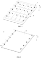
- FIG. 1 is an assembled perspective view of a first embodiment of a battery box according to the present invention.
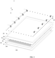
- FIG. 2 is an assembled perspective view of a heat exchange assembly of the battery box of FIG. 1 .
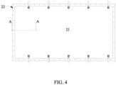
- FIG. 3 is an exploded view of FIG. 2 .
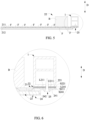
- FIG. 4 is a top view of FIG. 2 .
- FIG. 5 is a partial cross-section view of FIG. 4 .
- FIG. 6 is an enlarged view of FIG. 5 indicated by a circle.
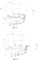
- FIG. 7 to FIG. 14 are enlarged views of second to ninth embodiments of the battery box according to the present invention.
- a battery box according to the present invention comprises a lower frame body 1 and a heat exchange assembly 2.
- a lower frame body 1 is closed in a circumferential direction and opened in an up-down direction D.
- the lower frame body 1 can be made of metal, such as aluminum alloy.
- the lower frame body 1 can be a die casting member or an extrusion profile.
- the heat exchange assembly 2 is fixed below the lower frame body 1 at a circumferential edge of the heat exchange assembly 2, the heat exchange assembly 2 and the lower frame body 1 form an accommodating space which is opened upwardly and used to accommodate the battery B.
- the heat exchange assembly 2 comprises a heat exchange plate 21, a heat insulating pad 22, a temperature preserving pad 23 and a protective plate 24.
- the heat exchange assembly 2 further comprises a fixing member 25.
- the battery B is generally arranged in the form of a battery module, that is, a plurality of batteries B are arranged together to form a unit module.
- the battery B may generally comprise a case and an electrode assembly and an electrolyte which are received in the case.
- the electrode assembly comprises a positive electrode plate, a negative electrode plate and a separator.
- the battery B may be a can-type (or rigid case) battery, and accordingly, the case comprises a cap assembly and an outer case assembled with the cap assembly; or the battery B may be a pouch-type (or flexible case) battery, the case is made of a packaging film (such as an aluminum plastic film).
- the heat exchange plate 21 is provided with a flow passage F therein for a heat exchange medium to flow, a portion of the heat exchange plate 21 provided with the flow passage F is used to support the battery B and exchange heat with the battery B.
- the heat exchange plate 21 comprises an upper plate 211 and a lower plate 212.
- the upper plate 211 and the lower plate 212 enclose to form the flow passage F, for example by stamping the upper plate 211 and/or the lower plate 212.
- the heat exchange plate 21 is made of a material having high thermal conductivity, preferably a metal material, and more preferably an aluminum alloy material.
- the heat insulating pad 22 comprises a first part 221 having a ring shape, and the first part 221 surrounds an entire circumferential edge of the heat exchange plate 21 outside the flow passage F and is provided above an upper surface U211 of the circumferential edge of the heat exchange plate 21, the first part 221 of the heat insulating pad 22 and the circumferential edge of the heat exchange plate 21 are stacked in the up-down direction D, the first part 221 of the heat insulating pad 22 is sandwiched between a lower surface of the lower frame body 1 and the upper surface U211 of the circumferential edge of the heat exchange plate 21.
- a material of the heat insulating pad 22 may be a composite material, such as an epoxy resin pad, of course, it is not limited thereto, and any suitable pad having high heat insulating properties may be used.
- At least a portion of the temperature preserving pad 23 is provided below the heat exchange plate 21, and the temperature preserving pad 23 at least covers the portion of the heat exchange plate 21 in which the flow passage F is provided. Therefore, at least the heat transfer of the heat exchange plate 21 in a downward direction is blocked, thereby preserving temperature of the battery B.
- a material of the temperature preserving pad 23 may be a heat insulating cotton, a foam or the like.
- the protective plate 24 supports the temperature preserving pad 23 and the heat exchange plate 21 from below.
- a material of the protective plate 24 is preferably a material with strong impact resistance, such as aluminum alloy, stainless steel, high-strength steel, hot-dip (DP) galvanized bidirectional high-strength alloy steel, etc. Therefore, under the impact of an external force, the protective plate 24 prevents the heat exchange plate 21 from failure due to damage by the external force.
- the heat insulating pad 22 can be configured in a variety of forms, which are specifically described below.
- the protective plate 24 comprises a peripheral portion 241 which is ring-shaped and a recessed portion 242 which is recessed downwardly from an inner side of the peripheral portion 241, the temperature preserving pad 23 is received in the recessed portion 242; the first part 221 of the heat insulating pad 22, the circumferential edge of the heat exchange plate 21 and the peripheral portion 241 of the protective plate 24 are stacked in the up-down direction D; an outer side surface S221 of the first part 221 of the heat insulating pad 22, an outer side surface S211 of the circumferential edge of the heat exchange plate 21 and an outer side surface S241 of the peripheral portion 241 of the protective plate 24 are flush with each other.
- the flush arrangement helps to improve the aesthetics of the appearance of the battery box.
- the protective plate 24 comprises a peripheral portion 241 which is ring-shaped and a recessed portion 242 which recessed downwardly from an inner side of the peripheral portion 241, the temperature preserving pad 23 is received in the recessed portion 242; an outer side surface S241 of the peripheral portion 241 of the protective plate 24 protrudes outwardly with respect to an outer side surface S211 of the circumferential edge of the heat exchange plate 21; the heat insulating pad 22 further comprises a second part 222, the second part 222 bends downwardly from the first part 221 and extends to surround the outer side surface S211 of the circumferential edge of the heat exchange plate 21 from outside.
- heat insulating from outside i.e., along the circumferential direction and the radial direction
- the outer side surface S211 of the circumferential edge of the heat exchange plate 21 is performed by the second part 222 of the heat insulating pad 22, thereby reinforcing the heat insulating on the basis of the first portion 221, in turn improving the heat insulating effect to the heat exchange plate 21, and improving the stability and constancy of the operating temperature of the battery B.
- the outer side surface S211 is also protected against damage caused by direct impact on the outer side surface S211.
- the heat insulating pad 22 further comprises a third part 223, the third part 223 bends inwardly from the second part 222 and extends to below a lower surface L211 of the circumferential edge of the heat exchange plate 21, the third part 223 is sandwiched by an upper surface U241 of the peripheral portion 241 of the protective plate 24 and the lower surface L211 of the circumferential edge of the heat exchange plate 21 in the up-down direction D.
- the second part 222 can not only strengthen the fixing of the second part 222, but also insulate heat from below the lower surface L211 of the circumferential edge of the heat exchange plate 21, so that the third part 223, the first part 221 and the second part 222 together achieve multi-directional heat insulation in the upward, downward, circumferential and radial directions, which further improves the temperature control effect of the battery box, and improves the stability and constancy of the operating temperature of the battery B.
- the outer side surface S211 of the circumferential edge of the heat exchange plate 21 is wrapped by the first part 221, the second part 222 and the third part 223 of the heat insulating pad 22, which improves the buffer effect of the circumferential edge of the heat exchange plate 21.
- the heat insulating pad 22 further comprises a third part 223, the third part 223 bends inwardly from the second part 222, extends to below a lower surface L211 of the circumferential edge of the heat exchange plate 21 and further extends into the recessed portion 242 of the protective plate 24,
- the temperature preserving pad 23 comprises a main body 230 and a protruding portion 231 which is ring-shaped and protrudes upwardly from the main body 230, and the protruding portion 231 and a portion of the third part 223 which is located in the recessed portion 242 of the protective plate 24 abut against each other in the up-down direction D.
- the fourth embodiment shown in FIG. 9 is similar to the third embodiment shown in FIG. 8 , but differs in the extension extent of the heat insulating pad 22 and the protruding portion 231 of the temperature preserving pad 23.
- the protruding portion 231 and the portion of the third part 223 of the heat insulating pad 22 which is located in the recessed portion 242 of the protective plate 24 abut against each other in the up-down direction D, the heat insulating pad 22 and the temperature preserving pad 23 are connected together, so that the first part 221, the second part 222, the third part 223 and the temperature preserving pad 23 together achieve multi-directional heat insulation to the entire heat exchange plate 21 in the upward, downward, circumferential and radial directions (not only achieve the heat insulation from the lower frame body 1 but also from the protective plate 24), and further improve the temperature control effect of the battery box, and improve the stability and constancy of the operating temperature of the battery B.
- the temperature preserving pad 23 can be configured in a variety of forms, which are specifically described below.
- the protective plate 24 comprises a peripheral portion 241 which is ring-shaped and a recessed portion 242 which is recessed downwardly from an inner side of the peripheral portion 241;
- the temperature preserving pad 23 comprises a main body 230 and an extending portion 232, the main body 230 is received in the recessed portion 242, the extending portion 232 extends outwardly from the main body 230 onto an entire lower surface L211 of the circumferential edge of the heat exchange plate 21 so that the extending portion 232 is sandwiched between an upper surface U241 of the peripheral portion 241 of the protective plate 24 and the lower surface L211 of the circumferential edge of the heat exchange plate 21.
- the fifth embodiment shown in FIG. 10 is similar to the third embodiment shown in FIG.
- the extending portion 232 can perform temperature preservation from below the lower surface L211 of the circumferential edge of the heat exchange plate 21, so that the extending portion 232 and the first part 221 of the heat insulating pad 22 together realize bidirectional heat insulation in the up-down direction D, which improves the temperature control effect of the battery box, and improves the stability and constancy of the operating temperature of the battery B.
- the protective plate 24 comprises a peripheral portion 241 which is ring-shaped and a recessed portion 242 which recessed downwardly from an inner side of the peripheral portion 241, an outer side surface S241 of the peripheral portion 241 of the protective plate 24 protrudes outwardly with respect to an outer side surface S211 of the circumferential edge of the heat exchange plate 21;
- the temperature preserving pad 23 comprises a main body 230, an extending portion 232 and a bending portion 233, the main body 230 is received in the recessed portion 242, the extending portion 232 extends outwardly from the main body 230 onto the lower surface L211 of the circumferential edge of the heat exchange plate 21 so that the extending portion 232 is sandwiched between an upper surface U241 of the peripheral portion 241 of the protective plate 24 and the lower surface L211 of the circumferential edge of the heat exchange plate 21, the bending portion 233 bends upwardly from the extending portion 232 and extends to surround the outer side surface S211 of the circumfer
- the sixth embodiment shown in FIG. 11 can achieve an effect similar to that of the third embodiment shown in FIG. 8 , that is, the bending portion 233 of the temperature preserving pad 23 insulates heat from outside (i.e., the circumferential direction and the radial direction) the outer side surface S211 of the circumferential edge of the heat exchange plate 21, so that the extending portion 232 and the bending portion 233 of the temperature preserving pad 23 and the first part 221 of the heat insulating pad 22 together realize multi-directional heat insulation in the upward, downward, circumferential and radial directions, thereby further improving the temperature control effect of the battery box, and improving the stability and constancy of the operating temperature of battery B. Furthermore, the sixth embodiment shown in FIG.
- the main body 230, the extending portion 232 and the bending portion 233 (in other words, the entire thermal insulation pad 23) of the temperature preserving pad 23 and the first part 221 of the heat insulating pad 22 together realize multi-directional heat insulation to the entire heat exchange plate 21 in the upward, downward, circumferential and radial directions (realize not only the heat insulation between the heat exchange plate 21 and the lower frame body 1, but also temperature preservation (that is heat insulation)between the heat exchange plate 21 and the protective plate 24), and further improve the temperature control effect of the battery box, improve the stability and constancy of the operating temperature of the battery B.
- the seventh embodiment shown in FIG. 12 on the basis of the sixth embodiment shown in FIG.
- the temperature preserving pad 23 further comprises a folding-back portion 234, the folding-back portion 234 bends inwardly from the bending portion 233 and extends to the upper surface U211 of the circumferential edge of the heat exchange plate 21.
- the folding-back portion 234 facilitates the fixing of the bending portion 233, while forming the double-layer heat insulation over the upper surface U211 of the circumferential edge of the heat exchange plate 21,thereby reinforcing the heat insulating effect between the heat exchange plate 21 and the lower frame 1 in the upward direction.
- a positional relationship of the folding-back portion 234 and the first part 221 of the heat insulating pad 22 may be as shown in FIG. 12 , that is, the folding-back portion 234 of the temperature preserving pad 23 is sandwiched between the first part 221 of the heat insulating pad 22 and the upper surface U211 of the circumferential edge of the heat exchange plate 21.
- a positional relationship of the folding-back portion 234 and the first part 221 of the heat insulating pad 22 may also be as shown in FIG. 13 .
- the first part 221 of the heat insulating pad 22 is sandwiched between the folding-back portion 234 of the temperature preserving pad 23 and the upper surface U211 of the circumferential edge of the heat exchange plate 21.
- the temperature preserving pad 23 and the heat insulating pad 22 are integrally formed.
- the temperature preserving pad 23 and the heat insulating pad 22 can be made of the same material, thereby saving manufacturing cost.
- the first part 221 of the heat insulating pad 22 is formed by the folding-back portion 234 of the temperature preserving pad 23, and vice versa, that is, other portions, such as the extending portion 232 and the bending portion 233.
- the temperature preserving pad 23 and the heat insulating pad 22 are formed separately.
- a fixing member 25 is used to fix the heat exchange plate 21, the heat insulating pad 22, the temperature preserving pad 23 and the protective plate 24 to the lower frame body 1.
- the fixing member 25 can take any suitable form, such as a rivet or a combination of bolt and nut.
- the material of the fixing member 25 is preferably made of a material having low thermal conductivity, such as a plastic member.
- a battery box comprising: a lower frame body (1) closed in a circumferential direction and opened in an up-down direction (D); and a heat exchange assembly (2) fixed below the lower frame body (1) at a circumferential edge of the heat exchange assembly (2), the heat exchange assembly (2) and the lower frame body (1) forming an accommodating space which is opened upwardly and used to accommodate a battery (B), the heat exchange assembly (2) comprising a heat exchange plate (21), a heat insulating pad (22), a temperature preserving pad (23) and a protective plate (24); wherein the heat exchange plate (21) is provided with a flow passage (F) therein for a heat exchange medium to flow, a portion of the heat exchange plate (21) provided with the flow passage (F) is used to support the battery (B) and exchange heat with the battery (B); the heat insulating pad (22) comprises a first part (221), the first part (221) has a ring shape, the first part (221) surrounds an entire circumferential edge of the heat exchange plate (21) outside the flow passage
- the protective plate (24) comprises a peripheral portion (241) which is ring-shaped and a recessed portion (242) which is recessed downwardly from an inner side of the peripheral portion (241), the temperature preserving pad (23) is received in the recessed portion (242); the first part (221) of the heat insulating pad (22), the circumferential edge of the heat exchange plate (21) and the peripheral portion (241) of the protective plate (24) are stacked in the up-down direction (D); an outer side surface (S221) of the first part (221) of the heat insulating pad (22), an outer side surface (S211) of the circumferential edge of the heat exchange plate (21) and an outer side surface (S241) of the peripheral portion (241) of the protective plate (24) are flush with each other.
- the protective plate (24) comprises a peripheral portion (241) which is ring-shaped and a recessed portion (242) which recessed downwardly from an inner side of the peripheral portion (241), the temperature preserving pad (23) is received in the recessed portion (242); an outer side surface (S241) of the peripheral portion (241) of the protective plate (24) protrudes outwardly with respect to an outer side surface (S211) of the circumferential edge of the heat exchange plate (21); the heat insulating pad (22) further comprises a second part (222), the second part (222) bends downwardly from the first part (221) and extends to surround the outer side surface (S211) of the circumferential edge of the heat exchange plate (21) from outside.
- the heat insulating pad (22) further comprises a third part (223); the third part (223) bends inwardly from the second part (222) and extends to below a lower surface (L211) of the circumferential edge of the heat exchange plate (21), the third part (223) is sandwiched by an upper surface (U241) of the peripheral portion (241) of the protective plate (24) and the lower surface (L211) of the circumferential edge of the heat exchange plate (21) in the up-down direction (D).
- the heat insulating pad (22) further comprises a third part (223), the third part (223) bends inwardly from the second part (222) and extends to below a lower surface (L211) of the circumferential edge of the heat exchange plate (21) and further extends into the recessed portion (242) of the protective plate (24);
- the temperature preserving pad (23) comprises a main body (230) and a protruding portion (231) which is ring-shaped and protrudes upwardly from the main body (230), and the protruding portion (231) and a portion of the third part (223) which is located in the recessed portion (242) of the protective plate (24) abut against each other in the up-down direction (D).
- the protective plate (24) comprises a peripheral portion (241) which is ring-shaped and a recessed portion (242) which is recessed downwardly from an inner side of the peripheral portion (241);
- the temperature preserving pad (23) comprises a main body (230) and an extending portion (232), the main body (230) is received in the recessed portion (242), the extending portion (232) extends outwardly from the main body (230) onto an entire lower surface (L211) of the circumferential edge of the heat exchange plate (21) so that the extending portion (232) is sandwiched between an upper surface (U241) of the peripheral portion (241) of the protective plate (24) and the lower surface (L211) of the circumferential edge of the heat exchange plate (21).
- the protective plate (24) comprises a peripheral portion (241) which is ring-shaped and a recessed portion (242) which recessed downwardly from an inner side of the peripheral portion (241); an outer side surface (S241) of the peripheral portion (241) of the protective plate (24) protrudes outwardly with respect to an outer side surface (S211) of the circumferential edge of the heat exchange plate (21);
- the temperature preserving pad (23) comprises a main body (230), an extending portion (232) and a bending portion (233), the main body (230) is received in the recessed portion (242), the extending portion (232) extends outwardly from the main body (230) onto a lower surface (L211) of the circumferential edge of the heat exchange plate (21) so that the extending portion (232) is sandwiched between an upper surface (U241) of the peripheral portion (241) of the protective plate (24) and the lower surface (L211) of the circumferential edge of the heat exchange plate (21), the
- Clause 8 The battery box according to clause 7, wherein the temperature preserving pad (23) further comprises a folding-back portion (234), the folding-back portion (234) bends inwardly from the bending portion (233) and extends to the upper surface (U211) of the circumferential edge of the heat exchange plate (21).
- Clause 9 The battery box according to clause 8, wherein the folding-back portion (234) of the temperature preserving pad (23) is sandwiched between the first part (221) of the heat insulating pad (22) and the upper surface (U211) of the circumferential edge of the heat exchange plate (21).
- Clause 10 The battery box according to clause 8, wherein the first part (221) of the heat insulating pad (22) is sandwiched between the folding-back portion (234) of the temperature preserving pad (23) and the upper surface (U211) of the circumferential edge of the heat exchange plate (21).
- Clause 11 The battery box according to clause 5, 7 or 8, wherein the temperature preserving pad (23) and the heat insulating pad (22) are integrally formed.
Landscapes
- Chemical & Material Sciences (AREA)
- Chemical Kinetics & Catalysis (AREA)
- Electrochemistry (AREA)
- General Chemical & Material Sciences (AREA)
- Engineering & Computer Science (AREA)
- Manufacturing & Machinery (AREA)
- Secondary Cells (AREA)
- Battery Mounting, Suspending (AREA)
- Sealing Battery Cases Or Jackets (AREA)
Applications Claiming Priority (2)
| Application Number | Priority Date | Filing Date | Title |
|---|---|---|---|
| CN201822246290.4U CN209401679U (zh) | 2018-12-29 | 2018-12-29 | 电池箱 |
| EP19216900.1A EP3675221B1 (de) | 2018-12-29 | 2019-12-17 | Batteriekasten |
Related Parent Applications (2)
| Application Number | Title | Priority Date | Filing Date |
|---|---|---|---|
| EP19216900.1A Division EP3675221B1 (de) | 2018-12-29 | 2019-12-17 | Batteriekasten |
| EP19216900.1A Division-Into EP3675221B1 (de) | 2018-12-29 | 2019-12-17 | Batteriekasten |
Publications (2)
| Publication Number | Publication Date |
|---|---|
| EP4246689A2 true EP4246689A2 (de) | 2023-09-20 |
| EP4246689A3 EP4246689A3 (de) | 2025-04-09 |
Family
ID=67897061
Family Applications (4)
| Application Number | Title | Priority Date | Filing Date |
|---|---|---|---|
| EP23190426.9A Pending EP4246689A3 (de) | 2018-12-29 | 2019-12-17 | Batteriekasten |
| EP23190424.4A Pending EP4246688A3 (de) | 2018-12-29 | 2019-12-17 | Batteriekasten |
| EP23190398.0A Pending EP4246687A3 (de) | 2018-12-29 | 2019-12-17 | Batteriekasten |
| EP19216900.1A Active EP3675221B1 (de) | 2018-12-29 | 2019-12-17 | Batteriekasten |
Family Applications After (3)
| Application Number | Title | Priority Date | Filing Date |
|---|---|---|---|
| EP23190424.4A Pending EP4246688A3 (de) | 2018-12-29 | 2019-12-17 | Batteriekasten |
| EP23190398.0A Pending EP4246687A3 (de) | 2018-12-29 | 2019-12-17 | Batteriekasten |
| EP19216900.1A Active EP3675221B1 (de) | 2018-12-29 | 2019-12-17 | Batteriekasten |
Country Status (5)
| Country | Link |
|---|---|
| US (1) | US11258119B2 (de) |
| EP (4) | EP4246689A3 (de) |
| CN (1) | CN209401679U (de) |
| HU (1) | HUE065047T2 (de) |
| WO (1) | WO2020135155A1 (de) |
Families Citing this family (16)
| Publication number | Priority date | Publication date | Assignee | Title |
|---|---|---|---|---|
| CN209401679U (zh) | 2018-12-29 | 2019-09-17 | 宁德时代新能源科技股份有限公司 | 电池箱 |
| EP3937295A4 (de) * | 2019-03-05 | 2023-07-19 | Aiways Automobile Co., Ltd | Batteriepack |
| CN110620197A (zh) * | 2019-09-24 | 2019-12-27 | 北京海纳川汽车部件股份有限公司 | 电池箱组件、底护板以及车辆 |
| WO2023004724A1 (zh) * | 2021-07-29 | 2023-02-02 | 宁德时代新能源科技股份有限公司 | 换热构件及其制造方法和制造系统、电池以及用电装置 |
| CN114430087B (zh) * | 2022-01-21 | 2024-03-29 | 北京博瑞翔伦科技发展有限公司 | 具有防水功能的边缘计算装置的电池存放机构 |
| US12275298B2 (en) | 2022-03-23 | 2025-04-15 | Ford Global Technologies, Llc | Traction battery packs with cell-to-pack battery systems housed within irregularly shaped enclosures |
| US12525637B2 (en) | 2022-03-23 | 2026-01-13 | Ford Global Technologies, Llc | Traction battery pack assembling method |
| US12567642B2 (en) | 2022-03-23 | 2026-03-03 | Ford Global Technologies, Llc | Shim systems for traction battery packs |
| US12230826B2 (en) | 2022-03-23 | 2025-02-18 | Ford Global Technologies, Llc | Methods for assembling traction battery packs |
| US12424695B2 (en) | 2022-03-23 | 2025-09-23 | Ford Global Technologies, Llc | Retention assemblies for traction battery packs with cell-to-pack battery systems |
| US12506215B2 (en) | 2022-03-23 | 2025-12-23 | Ford Global Technologies, Llc | Enclosure cover attachment configurations for traction battery packs with cell-to-pack battery systems |
| US12603373B2 (en) | 2022-03-23 | 2026-04-14 | Ford Global Technologies, Llc | Traction battery pack assembling method |
| US12479327B2 (en) | 2022-03-23 | 2025-11-25 | Ford Global Technologies, Llc | Traction battery pack cell stack removal method and battery pack assembly |
| US12374750B2 (en) | 2022-03-23 | 2025-07-29 | Ford Global Technologies, Llc | Traction battery pack assembling method |
| FR3145649A1 (fr) * | 2023-02-06 | 2024-08-09 | Renault S.A.S | Module de batterie comprenant une plaque de traitement thermique et procédé d’assemblage dudit module |
| CN116826256B (zh) * | 2023-07-17 | 2025-01-03 | 中创新航科技集团股份有限公司 | 电池装置 |
Family Cites Families (29)
| Publication number | Priority date | Publication date | Assignee | Title |
|---|---|---|---|---|
| US20080193830A1 (en) * | 2006-10-13 | 2008-08-14 | Enerdel, Inc. | Battery assembly with temperature control device |
| TWI419391B (zh) * | 2009-12-25 | 2013-12-11 | Ind Tech Res Inst | 電池系統中的散熱與熱失控擴散防護結構 |
| JP5464168B2 (ja) * | 2010-06-04 | 2014-04-09 | 株式会社デンソー | 電源装置 |
| US8435668B2 (en) * | 2010-07-23 | 2013-05-07 | GM Global Technology Operations LLC | Prismatic battery cell with integrated cooling passages and assembly frame |
| JP5580282B2 (ja) * | 2011-12-09 | 2014-08-27 | 本田技研工業株式会社 | バッテリの冷却装置 |
| FR2986663B1 (fr) * | 2012-02-03 | 2014-08-01 | Renault Sas | Module d'accumulateurs equipe d'une cellule peltier |
| US9379420B2 (en) * | 2012-03-29 | 2016-06-28 | Lg Chem, Ltd. | Battery system and method for cooling the battery system |
| JP2014183013A (ja) * | 2013-03-21 | 2014-09-29 | Sumitomo Electric Ind Ltd | 電池パック |
| JP6174381B2 (ja) * | 2013-06-06 | 2017-08-02 | 日立オートモティブシステムズ株式会社 | 蓄電ブロックおよび蓄電モジュール |
| US10347894B2 (en) * | 2017-01-20 | 2019-07-09 | Tesla, Inc. | Energy storage system |
| US9362598B2 (en) * | 2014-08-25 | 2016-06-07 | Ford Global Technologies, Llc | Traction battery assembly with thermal device |
| US20160064708A1 (en) * | 2014-08-26 | 2016-03-03 | Ford Global Technologies, Llc | Angled Battery Cell Configuration for a Traction Battery Assembly |
| US9634364B2 (en) * | 2014-10-28 | 2017-04-25 | Ford Global Technologies, Llc | Support structure for traction battery assembly with integrated thermal plate |
| US9786969B2 (en) * | 2014-11-11 | 2017-10-10 | Ford Global Technologies, Llc | Magnetically controlled traction battery thermal plate |
| CN204348869U (zh) | 2014-12-18 | 2015-05-20 | 北汽福田汽车股份有限公司 | 水冷组件和具有其的汽车 |
| US9553344B2 (en) * | 2015-04-15 | 2017-01-24 | Ford Global Technologies, Llc | Peristaltic pump for traction battery thermal management system |
| US9533600B1 (en) * | 2015-09-03 | 2017-01-03 | GM Global Technology Operations LLC | Structurally integrated propulsion battery |
| CN205211817U (zh) * | 2015-12-09 | 2016-05-04 | 北汽福田汽车股份有限公司 | 一种电池包箱体及具有其的车辆 |
| US20180123201A1 (en) * | 2016-10-28 | 2018-05-03 | Inevit, Llc | Battery module cooling tube including an integrated turbulator component and method thereof |
| US11605847B2 (en) * | 2016-11-04 | 2023-03-14 | Ford Global Technologies, Llc | Thermal exchange plate assembly for vehicle battery |
| KR101916429B1 (ko) * | 2017-03-30 | 2018-11-07 | 엘지전자 주식회사 | 차량용 배터리 팩 및 차량 |
| CN207021300U (zh) | 2017-05-11 | 2018-02-16 | 东莞市迈泰热传科技有限公司 | 一种电动汽车的电池包用机箱 |
| CN207183375U (zh) * | 2017-09-20 | 2018-04-03 | 宁德时代新能源科技股份有限公司 | 箱体及电池包 |
| CN207818674U (zh) * | 2017-12-27 | 2018-09-04 | 宁德时代新能源科技股份有限公司 | 电池包 |
| CN207676971U (zh) * | 2017-12-27 | 2018-07-31 | 宁德时代新能源科技股份有限公司 | 电池包 |
| CN108365156B (zh) * | 2018-04-24 | 2024-06-18 | 北京新能源汽车股份有限公司 | 电池包和车辆 |
| KR102603060B1 (ko) * | 2018-06-08 | 2023-11-16 | 현대자동차주식회사 | 차량용 배터리 냉각 장치 및 그 제조 방법 |
| US20200091479A1 (en) * | 2018-09-13 | 2020-03-19 | Tiveni MergeCo Inc. | Battery module with bottom plate that functions as a heat spreader |
| CN209401679U (zh) * | 2018-12-29 | 2019-09-17 | 宁德时代新能源科技股份有限公司 | 电池箱 |
-
2018
- 2018-12-29 CN CN201822246290.4U patent/CN209401679U/zh active Active
-
2019
- 2019-12-17 EP EP23190426.9A patent/EP4246689A3/de active Pending
- 2019-12-17 EP EP23190424.4A patent/EP4246688A3/de active Pending
- 2019-12-17 EP EP23190398.0A patent/EP4246687A3/de active Pending
- 2019-12-17 EP EP19216900.1A patent/EP3675221B1/de active Active
- 2019-12-17 HU HUE19216900A patent/HUE065047T2/hu unknown
- 2019-12-17 WO PCT/CN2019/125998 patent/WO2020135155A1/zh not_active Ceased
- 2019-12-18 US US16/719,663 patent/US11258119B2/en active Active
Also Published As
| Publication number | Publication date |
|---|---|
| HUE065047T2 (hu) | 2024-04-28 |
| WO2020135155A1 (zh) | 2020-07-02 |
| EP4246688A3 (de) | 2025-04-09 |
| EP4246689A3 (de) | 2025-04-09 |
| US11258119B2 (en) | 2022-02-22 |
| EP4246687A3 (de) | 2025-04-09 |
| US20200212523A1 (en) | 2020-07-02 |
| EP4246687A2 (de) | 2023-09-20 |
| CN209401679U (zh) | 2019-09-17 |
| EP4246688A2 (de) | 2023-09-20 |
| EP3675221A1 (de) | 2020-07-01 |
| EP3675221B1 (de) | 2023-11-15 |
Similar Documents
| Publication | Publication Date | Title |
|---|---|---|
| EP3675221B1 (de) | Batteriekasten | |
| EP3675207B1 (de) | Batteriekasten | |
| US20250210751A1 (en) | Battery box | |
| US20110262782A1 (en) | Battery explosion-proof structure and power battery having the same | |
| US20120015219A1 (en) | Explosion-proof device for use in power batteries | |
| CN215911486U (zh) | 电池的顶盖以及电池 | |
| CN217158358U (zh) | 顶盖组件与单体电池 | |
| US20140205872A1 (en) | Rechargeable battery having desirable safety performance | |
| CN207250598U (zh) | 电池托盘 | |
| JP6275621B2 (ja) | 容器の防爆弁の構造 | |
| CN222953221U (zh) | 一种锂电池盖组件 | |
| KR20260046469A (ko) | 열교환 구조체, 배터리 팩 및 전기 디바이스 | |
| KR102723877B1 (ko) | 전지의 실링 구조 | |
| KR102717621B1 (ko) | 전지의 실링 구조 | |
| CN109148767A (zh) | 一种聚合物电芯及聚合物电池包 | |
| JP2011181346A (ja) | 電池用ケース | |
| CN213212250U (zh) | 一种新型锂电池滑轨式铝桶 | |
| CN223242999U (zh) | 压盖及空调器 | |
| US12362345B2 (en) | Battery cell, battery, and electric device | |
| CN223956668U (zh) | 一种电芯盖板及电芯 | |
| CN223109013U (zh) | 电池的顶盖及电池 | |
| CN222507797U (zh) | 一种电池的下塑胶组件、盖板组件、电池以及光伏设备 | |
| CN105792624B (zh) | 一种汽车散热装置 | |
| US20190058169A1 (en) | Secondary battery head cover assembly, secondary battery including the same and assembling method thereof | |
| EP3008765B1 (de) | Batteriedeckelbaugruppe und batterie damit |
Legal Events
| Date | Code | Title | Description |
|---|---|---|---|
| PUAI | Public reference made under article 153(3) epc to a published international application that has entered the european phase |
Free format text: ORIGINAL CODE: 0009012 |
|
| STAA | Information on the status of an ep patent application or granted ep patent |
Free format text: STATUS: THE APPLICATION HAS BEEN PUBLISHED |
|
| AC | Divisional application: reference to earlier application |
Ref document number: 3675221 Country of ref document: EP Kind code of ref document: P |
|
| AK | Designated contracting states |
Kind code of ref document: A2 Designated state(s): AL AT BE BG CH CY CZ DE DK EE ES FI FR GB GR HR HU IE IS IT LI LT LU LV MC MK MT NL NO PL PT RO RS SE SI SK SM TR |
|
| RAP1 | Party data changed (applicant data changed or rights of an application transferred) |
Owner name: CONTEMPORARY AMPEREX TECHNOLOGY(HONG KONG) LIMITED |
|
| REG | Reference to a national code |
Ref country code: DE Ref legal event code: R079 Free format text: PREVIOUS MAIN CLASS: H01M0050240000 Ipc: H01M0010613000 |
|
| PUAL | Search report despatched |
Free format text: ORIGINAL CODE: 0009013 |
|
| AK | Designated contracting states |
Kind code of ref document: A3 Designated state(s): AL AT BE BG CH CY CZ DE DK EE ES FI FR GB GR HR HU IE IS IT LI LT LU LV MC MK MT NL NO PL PT RO RS SE SI SK SM TR |
|
| RIC1 | Information provided on ipc code assigned before grant |
Ipc: H01M 50/209 20210101ALI20250304BHEP Ipc: H01M 50/24 20210101ALI20250304BHEP Ipc: H01M 10/6556 20140101ALI20250304BHEP Ipc: H01M 10/6554 20140101ALI20250304BHEP Ipc: H01M 10/613 20140101AFI20250304BHEP |
|
| STAA | Information on the status of an ep patent application or granted ep patent |
Free format text: STATUS: REQUEST FOR EXAMINATION WAS MADE |
|
| 17P | Request for examination filed |
Effective date: 20250423 |