EP4245601A1 - Support, battery assembly, electric device and battery swapping system - Google Patents
Support, battery assembly, electric device and battery swapping system Download PDFInfo
- Publication number
- EP4245601A1 EP4245601A1 EP22874277.1A EP22874277A EP4245601A1 EP 4245601 A1 EP4245601 A1 EP 4245601A1 EP 22874277 A EP22874277 A EP 22874277A EP 4245601 A1 EP4245601 A1 EP 4245601A1
- Authority
- EP
- European Patent Office
- Prior art keywords
- battery
- support
- mounting hole
- connecting element
- magnetic element
- Prior art date
- Legal status (The legal status is an assumption and is not a legal conclusion. Google has not performed a legal analysis and makes no representation as to the accuracy of the status listed.)
- Pending
Links
- 238000001514 detection method Methods 0.000 claims abstract description 19
- 230000007246 mechanism Effects 0.000 claims abstract description 12
- 238000010586 diagram Methods 0.000 description 14
- 230000003247 decreasing effect Effects 0.000 description 7
- 230000009471 action Effects 0.000 description 5
- 238000013459 approach Methods 0.000 description 5
- VNWKTOKETHGBQD-UHFFFAOYSA-N methane Chemical compound C VNWKTOKETHGBQD-UHFFFAOYSA-N 0.000 description 4
- 238000003780 insertion Methods 0.000 description 3
- 230000037431 insertion Effects 0.000 description 3
- 230000000694 effects Effects 0.000 description 2
- 239000002803 fossil fuel Substances 0.000 description 2
- 230000005389 magnetism Effects 0.000 description 2
- 238000000034 method Methods 0.000 description 2
- 230000004048 modification Effects 0.000 description 2
- 238000012986 modification Methods 0.000 description 2
- 239000003345 natural gas Substances 0.000 description 2
- 230000008569 process Effects 0.000 description 2
- 238000011160 research Methods 0.000 description 2
- 239000000126 substance Substances 0.000 description 2
- 235000015842 Hesperis Nutrition 0.000 description 1
- 235000012633 Iberis amara Nutrition 0.000 description 1
- 230000006872 improvement Effects 0.000 description 1
- 230000003993 interaction Effects 0.000 description 1
- 230000005415 magnetization Effects 0.000 description 1
- 239000002184 metal Substances 0.000 description 1
Images

Classifications
-
- B—PERFORMING OPERATIONS; TRANSPORTING
- B60—VEHICLES IN GENERAL
- B60S—SERVICING, CLEANING, REPAIRING, SUPPORTING, LIFTING, OR MANOEUVRING OF VEHICLES, NOT OTHERWISE PROVIDED FOR
- B60S5/00—Servicing, maintaining, repairing, or refitting of vehicles
- B60S5/06—Supplying batteries to, or removing batteries from, vehicles
-
- B—PERFORMING OPERATIONS; TRANSPORTING
- B60—VEHICLES IN GENERAL
- B60L—PROPULSION OF ELECTRICALLY-PROPELLED VEHICLES; SUPPLYING ELECTRIC POWER FOR AUXILIARY EQUIPMENT OF ELECTRICALLY-PROPELLED VEHICLES; ELECTRODYNAMIC BRAKE SYSTEMS FOR VEHICLES IN GENERAL; MAGNETIC SUSPENSION OR LEVITATION FOR VEHICLES; MONITORING OPERATING VARIABLES OF ELECTRICALLY-PROPELLED VEHICLES; ELECTRIC SAFETY DEVICES FOR ELECTRICALLY-PROPELLED VEHICLES
- B60L50/00—Electric propulsion with power supplied within the vehicle
- B60L50/50—Electric propulsion with power supplied within the vehicle using propulsion power supplied by batteries or fuel cells
- B60L50/60—Electric propulsion with power supplied within the vehicle using propulsion power supplied by batteries or fuel cells using power supplied by batteries
- B60L50/64—Constructional details of batteries specially adapted for electric vehicles
-
- B—PERFORMING OPERATIONS; TRANSPORTING
- B60—VEHICLES IN GENERAL
- B60R—VEHICLES, VEHICLE FITTINGS, OR VEHICLE PARTS, NOT OTHERWISE PROVIDED FOR
- B60R16/00—Electric or fluid circuits specially adapted for vehicles and not otherwise provided for; Arrangement of elements of electric or fluid circuits specially adapted for vehicles and not otherwise provided for
- B60R16/02—Electric or fluid circuits specially adapted for vehicles and not otherwise provided for; Arrangement of elements of electric or fluid circuits specially adapted for vehicles and not otherwise provided for electric constitutive elements
- B60R16/04—Arrangement of batteries
-
- H—ELECTRICITY
- H01—ELECTRIC ELEMENTS
- H01M—PROCESSES OR MEANS, e.g. BATTERIES, FOR THE DIRECT CONVERSION OF CHEMICAL ENERGY INTO ELECTRICAL ENERGY
- H01M50/00—Constructional details or processes of manufacture of the non-active parts of electrochemical cells other than fuel cells, e.g. hybrid cells
- H01M50/20—Mountings; Secondary casings or frames; Racks, modules or packs; Suspension devices; Shock absorbers; Transport or carrying devices; Holders
- H01M50/244—Secondary casings; Racks; Suspension devices; Carrying devices; Holders characterised by their mounting method
-
- H—ELECTRICITY
- H01—ELECTRIC ELEMENTS
- H01M—PROCESSES OR MEANS, e.g. BATTERIES, FOR THE DIRECT CONVERSION OF CHEMICAL ENERGY INTO ELECTRICAL ENERGY
- H01M50/00—Constructional details or processes of manufacture of the non-active parts of electrochemical cells other than fuel cells, e.g. hybrid cells
- H01M50/20—Mountings; Secondary casings or frames; Racks, modules or packs; Suspension devices; Shock absorbers; Transport or carrying devices; Holders
- H01M50/249—Mountings; Secondary casings or frames; Racks, modules or packs; Suspension devices; Shock absorbers; Transport or carrying devices; Holders specially adapted for aircraft or vehicles, e.g. cars or trains
-
- B—PERFORMING OPERATIONS; TRANSPORTING
- B60—VEHICLES IN GENERAL
- B60K—ARRANGEMENT OR MOUNTING OF PROPULSION UNITS OR OF TRANSMISSIONS IN VEHICLES; ARRANGEMENT OR MOUNTING OF PLURAL DIVERSE PRIME-MOVERS IN VEHICLES; AUXILIARY DRIVES FOR VEHICLES; INSTRUMENTATION OR DASHBOARDS FOR VEHICLES; ARRANGEMENTS IN CONNECTION WITH COOLING, AIR INTAKE, GAS EXHAUST OR FUEL SUPPLY OF PROPULSION UNITS IN VEHICLES
- B60K1/00—Arrangement or mounting of electrical propulsion units
- B60K1/04—Arrangement or mounting of electrical propulsion units of the electric storage means for propulsion
- B60K2001/0405—Arrangement or mounting of electrical propulsion units of the electric storage means for propulsion characterised by their position
- B60K2001/0438—Arrangement under the floor
-
- B—PERFORMING OPERATIONS; TRANSPORTING
- B60—VEHICLES IN GENERAL
- B60K—ARRANGEMENT OR MOUNTING OF PROPULSION UNITS OR OF TRANSMISSIONS IN VEHICLES; ARRANGEMENT OR MOUNTING OF PLURAL DIVERSE PRIME-MOVERS IN VEHICLES; AUXILIARY DRIVES FOR VEHICLES; INSTRUMENTATION OR DASHBOARDS FOR VEHICLES; ARRANGEMENTS IN CONNECTION WITH COOLING, AIR INTAKE, GAS EXHAUST OR FUEL SUPPLY OF PROPULSION UNITS IN VEHICLES
- B60K1/00—Arrangement or mounting of electrical propulsion units
- B60K1/04—Arrangement or mounting of electrical propulsion units of the electric storage means for propulsion
- B60K2001/0455—Removal or replacement of the energy storages
-
- B—PERFORMING OPERATIONS; TRANSPORTING
- B60—VEHICLES IN GENERAL
- B60L—PROPULSION OF ELECTRICALLY-PROPELLED VEHICLES; SUPPLYING ELECTRIC POWER FOR AUXILIARY EQUIPMENT OF ELECTRICALLY-PROPELLED VEHICLES; ELECTRODYNAMIC BRAKE SYSTEMS FOR VEHICLES IN GENERAL; MAGNETIC SUSPENSION OR LEVITATION FOR VEHICLES; MONITORING OPERATING VARIABLES OF ELECTRICALLY-PROPELLED VEHICLES; ELECTRIC SAFETY DEVICES FOR ELECTRICALLY-PROPELLED VEHICLES
- B60L53/00—Methods of charging batteries, specially adapted for electric vehicles; Charging stations or on-board charging equipment therefor; Exchange of energy storage elements in electric vehicles
- B60L53/80—Exchanging energy storage elements, e.g. removable batteries
-
- H—ELECTRICITY
- H01—ELECTRIC ELEMENTS
- H01M—PROCESSES OR MEANS, e.g. BATTERIES, FOR THE DIRECT CONVERSION OF CHEMICAL ENERGY INTO ELECTRICAL ENERGY
- H01M2220/00—Batteries for particular applications
- H01M2220/20—Batteries in motive systems, e.g. vehicle, ship, plane
-
- Y—GENERAL TAGGING OF NEW TECHNOLOGICAL DEVELOPMENTS; GENERAL TAGGING OF CROSS-SECTIONAL TECHNOLOGIES SPANNING OVER SEVERAL SECTIONS OF THE IPC; TECHNICAL SUBJECTS COVERED BY FORMER USPC CROSS-REFERENCE ART COLLECTIONS [XRACs] AND DIGESTS
- Y02—TECHNOLOGIES OR APPLICATIONS FOR MITIGATION OR ADAPTATION AGAINST CLIMATE CHANGE
- Y02T—CLIMATE CHANGE MITIGATION TECHNOLOGIES RELATED TO TRANSPORTATION
- Y02T10/00—Road transport of goods or passengers
- Y02T10/60—Other road transportation technologies with climate change mitigation effect
- Y02T10/70—Energy storage systems for electromobility, e.g. batteries
-
- Y—GENERAL TAGGING OF NEW TECHNOLOGICAL DEVELOPMENTS; GENERAL TAGGING OF CROSS-SECTIONAL TECHNOLOGIES SPANNING OVER SEVERAL SECTIONS OF THE IPC; TECHNICAL SUBJECTS COVERED BY FORMER USPC CROSS-REFERENCE ART COLLECTIONS [XRACs] AND DIGESTS
- Y02—TECHNOLOGIES OR APPLICATIONS FOR MITIGATION OR ADAPTATION AGAINST CLIMATE CHANGE
- Y02T—CLIMATE CHANGE MITIGATION TECHNOLOGIES RELATED TO TRANSPORTATION
- Y02T10/00—Road transport of goods or passengers
- Y02T10/60—Other road transportation technologies with climate change mitigation effect
- Y02T10/7072—Electromobility specific charging systems or methods for batteries, ultracapacitors, supercapacitors or double-layer capacitors
Definitions
- This application relates to the field of batteries, and specifically, to a support, a battery assembly, an electric device, and a battery swapping system.
- Batteries are widely applied to the new energy field, such as electric vehicles and new energy vehicles.
- New energy vehicles and electric vehicles have emerged as a key trend in the evolution of the automobile industry. After running out of power, a battery of a motor-powered vehicle or new energy vehicle needs to be replaced.
- the existing battery swapping device does not support fast battery swapping.
- Embodiments of this application are intended to provide a support, a battery assembly, an electric device, and a battery swapping system so as to resolve the priorart problem that a battery swapping device does not support fast battery swapping.
- an embodiment of this application provides a support configured to connect to a battery and an electric device body, where the support includes a support body and a magnetic element, and the support body is configured for mounting the battery.
- the magnetic element is mounted on the support body, where the magnetic element is configured for detection by a positioning apparatus of a battery swapping device, for positioning the support body and the battery swapping device.
- the support body can be configured for mounting the battery and connecting to the electric device body.
- the support body is provided with the magnetic element, and the magnetic element can produce a magnetic field for detection by the positioning apparatus of the battery swapping device, for fast positioning the support body and the battery swapping device, thus facilitating fast battery swapping by the battery swapping device.
- the support further includes a connecting element, where the connecting element is configured to connect the magnetic element and the support body.
- the support body is provided with a mounting hole, where the mounting hole is configured to accommodate at least part of the connecting element.
- a limiting structure is formed on the connecting element, where the limiting structure is configured to prevent the connecting element from leaving the mounting hole.
- connection element is conducive to mounting the magnetic element onto the support body.
- the limiting structure is formed on the connecting element, such that the connecting element accommodated in the mounting hole cannot leave the mounting hole, increasing the reliability of connection between the magnetic element and the support body and decreasing the risk of the magnetic element leaving the support body during use of the electric device body.
- the limiting structure includes a plurality of barbs spaced apart on the connecting element in a direction of the connecting element being inserted into the mounting hole, where the plurality of barbs are at least partly accommodated in the mounting hole.
- the barbs have a property of unidirectional passability. Therefore, in the foregoing technical solution, the barbs provided on the connecting element allow the connecting element to be inserted into the mounting hole while preventing the connecting element from leaving the mounting hole. This facilitates and simplifies mounting of the connecting element and guarantees the reliability of connection between the connecting element and the support body.
- the connecting element further includes a head portion and an extension portion, where the head portion is connected to one end of the extension portion.
- the extension portion is configured to be inserted into the mounting hole, and the limiting structure is provided on the extension portion.
- the head portion is configured to abut against the support body in the direction of the connecting element being inserted into the mounting hole, and the limiting structure is configured to prevent the extension portion from leaving the mounting hole in an opposite direction to the direction of the connecting element being inserted into the mounting hole.
- the head portion and the extension portion provided and the limiting structure provided on the extension portion when the connecting element is inserted, the head portion can abut against the support body to prevent the connecting element from being over-inserted into the support body or protruding out of the mounting hole.
- the limiting structure can prevent the extension portion from leaving the mounting hole in an opposite direction to the direction of the connecting element being inserted into the mounting hole. In this way, the connecting element is limited in the mounting hole so that the connecting element cannot leave the mounting hole, that is, the connecting element cannot be separated from the support body, making a firm connection between the connecting element and the support body.
- the support body is provided with a recess, where the recess is configured to accommodate the head portion.
- provision of the recess for accommodating the head portion reduces the height of the head portion protruding from the support body, decreasing the risk of damaging the head portion caused by collision with other structures.
- the connecting element includes the extension portion configured to be inserted into the mounting hole, where the extension portion includes a first arm and a second arm that are spaced apart, and both the first arm and the second arm are provided with the limiting structure.
- a gap is present between the first arm and the second arm.
- the connecting element When the connecting element is inserted into the mounting hole, the first arm and the second arm are simultaneously in contact with the hole wall of the mounting hole, and the first arm and the second arm can approach each other under the action of a force to reduce the volume of the extension portion, facilitating insertion of the extension portion into the mounting hole.
- the first arm and the second arm After the extension portion is inserted into the mounting hole, the first arm and the second arm reset due to losing the action of a force, and the limiting structures on the first arm and the second arm prevent the extension portion from leaving the mounting hole.
- At least part of the magnetic element is buried in the connecting element.
- the magnetic element being buried in the connecting element brings better strength and stability of connection between the magnetic element and the connecting element, decreasing the risk of the magnetic element being separated from the connecting element.
- the magnetic element includes a permanent magnet or an electromagnet.
- the permanent magnet can constantly produce a magnetic field for detection by the positioning apparatus of the battery swapping device. After energizing, the electromagnet also produces a magnetic field for detection by the positioning apparatus of the battery swapping device.
- the support body includes a frame body and at least one connecting beam.
- the frame body is provided with an accommodating portion.
- the connecting beam is connected to the frame body, where the connecting beam separates the accommodating portion into a plurality of accommodating spaces, each of the accommodating spaces is configured to accommodate at least one battery, and each connecting beam is provided with the magnetic element.
- the connecting beam is provided such that the accommodating portion is separated into the plurality of accommodating spaces for accommodating the battery.
- the batteries can be mounted in the accommodating spaces.
- the plurality of accommodating spaces can share the magnetic element provided on the connecting beam, for positioning. This helps to reduce the quantity of magnetic elements, decrease production costs, and improve positioning accuracy.
- the magnetic element is mounted at the bottom of the connecting beam.
- the battery swapping device replaces the battery from the lower side of the support body. Therefore, the magnetic element being provided at the bottom of the connecting beam makes the magnetic element closer to the battery swapping device. This helps the positioning apparatus of the battery swapping device to fast detect the magnetic element so as to position the support body and the battery swapping device.
- an embodiment of this application provides a battery assembly including the foregoing support and a battery, where the battery is mounted on the support.
- an embodiment of this application provides an electric device including an electric device body and the foregoing battery assembly, where the support of the battery assembly is mounted on the electric device body.
- an embodiment of this application provides a battery swapping system used to replace batteries for the foregoing electric device.
- the battery swapping system includes a battery swapping device, where the battery swapping device includes an execution mechanism and a positioning apparatus.
- the positioning apparatus is configured to perform detection for the magnetic element so as to position the battery swapping device and the support.
- the execution mechanism is configured to replace the battery of the electric device.
- the term "and/or" in this application describes only an association relationship for describing associated objects and represents that three relationships may exist.
- a and/or B may represent the following three cases: A alone, both A and B, and B alone.
- a character "/" in this specification generally indicates an "or" relationship between contextually associated objects.
- a plurality of means more than two (inclusive).
- a plurality of groups means more than two (inclusive) groups
- a plurality of pieces means more than two (inclusive) pieces.
- the terms “mount”, “connect”, “join”, and “fasten” should be understood in their general senses. For example, they may be a fixed connection, a detachable connection, or an integral connection, may be a mechanical connection or electrical connection, or may be a direct connection, an indirect connection via an intermediate medium, or an interaction between two elements. Persons of ordinary skill in the art can understand specific meanings of these terms in this application based on specific situations.
- Batteries are widely applied to the new energy field, such as electric vehicles and new energy vehicles.
- New energy vehicles and electric vehicles have emerged as a key trend in the evolution of the automobile industry. After running out of power, a battery of a motor-powered vehicle or new energy vehicle needs to be replaced.
- the existing battery swapping device does not support fast battery swapping.
- the battery swapping device before battery swapping by the existing battery swapping device, users need to park their vehicles at preset positions, and then the battery swapping device swaps batteries for the vehicles.
- users often have difficulties in parking their vehicles at the exact positions, resulting in the battery swapping device spending a long time in locating positions of the vehicles and the battery swapping device before swapping batteries for the vehicles.
- the vehicles cannot be adjusted in their positions when breaking down or having exhausted batteries, such that they cannot be parked at the preset positions.
- the battery swapping device also needs a long time to locate the relative positions of the vehicles and the battery swapping device.
- the battery swapping device can swap batteries only after the relative positions of the vehicles and the battery swapping devices are accurately located.
- the applicant has found through research that with a magnetic element mounted on the battery mounting support of the vehicles and a positioning apparatus provided on the battery swapping device, the positioning apparatus of the battery swapping device can perform detection for the magnetic element to fast position the support and the battery swapping device.
- a support including a support body and a magnetic element, where the support body is configured for mounting a battery.
- the magnetic element is mounted on the support body, where the magnetic element is configured for detection by a positioning apparatus of a battery swapping device, for positioning the support body and the battery swapping device.
- the support body of the support can be configured for mounting the battery and connecting to the electric device body.
- the support body is provided with the magnetic element, and the magnetic element can produce a magnetic field for detection by the positioning apparatus of the battery swapping device, for fast positioning the support body and the battery swapping device, thus facilitating fast battery swapping by the battery swapping device.
- An embodiment of this application provides an electric device that uses a battery as the power supply.
- the electric device may be but is not limited to an electric bicycle, an electric vehicle, a ship, or a spacecraft.
- the spacecraft may include airplanes, rockets, space shuttles, and spaceships.
- the electric device 1000 in an embodiment of the application being a vehicle is used as an example for description of the following embodiments.
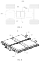
- FIG. 1 is a schematic structural diagram of an electric device 1000 according to some embodiments of this application.
- FIG. 2 is a schematic structural diagram of a battery assembly 10 according to some embodiments of this application.
- FIG. 3 is a schematic diagram of an overall structure of a support 120 according to some embodiments of this application.
- FIG. 4 is a schematic structural diagram of a support 120 in a first perspective according to some embodiments of this application.
- the electric device 1000 includes an electric device body 400 and the battery assembly 10, where the battery assembly 10 includes the support 120 and a battery 110.
- the support 120 is mounted on the electric device body 400, and the battery 110 is mounted on the support 120.
- the support 120 of the battery assembly 10 is mounted on the electric device body 400.
- the battery 110 and the electric device body 400 are connected via the support 120.
- the support 120 can provide an accommodating space 1211 for the battery 110, facilitating replacement of the battery 110.
- the electric device 1000 may be a fossil fuel vehicle, a natural-gas vehicle, or a new energy vehicle, where the new energy vehicle may be a battery electric vehicle, a hybrid electric vehicle, a range-extended vehicle, or the like.
- the battery 110 is provided inside the electric device 1000, and the battery 110 may be provided at the bottom, front, or rear of the electric device 1000.
- the battery 110 may be configured to supply power to the electric device 1000.
- the battery 110 may be used as an operational power source for the electric device 1000.
- the electric device 1000 may further include a motor 300 and a controller 500, where the controller 500 is configured to control the battery 110 to supply power to the motor 300, for example, to satisfy the power needs of start, navigation, and driving of the electric device 1000.
- the battery 110 can be used as not only the operational power source for the electric device 1000 but also a driving power source for the electric device 1000, replacing or partially replacing fossil fuel or natural gas to provide driving traction for the electric device 1000.
- An embodiment of this application provides a support 120 configured to connect to a battery 110 and an electric device body 400, where the support 120 includes a support body and a magnetic element 126, and the support body is configured for mounting the battery 110.
- the magnetic element 126 is mounted on the support body, where the magnetic element 126 is configured for detection by a positioning apparatus 620 of a battery swapping device 600, for positioning the support body and the battery swapping device 600.
- the magnetic element 126 is a substance or structure having magnetism.
- the magnetic element 126 includes a permanent magnet or an electromagnet and also includes a structure magnetized (magnetization means a process making an originally non-magnetic metal magnetic under the action of a magnetic substance).
- the permanent magnet can constantly produce a magnetic field for detection by the positioning apparatus 620 of the battery swapping device 600. After energizing, the electromagnet also produces a magnetic field for detection by the positioning apparatus 620 of the battery swapping device 600.
- a permanent magnet and an electromagnet are not apt to lose magnetism and thus have better effects.
- the support body of the support 120 provided in the embodiment of this application can be configured for mounting the battery 110 and connecting to the electric device body 400.
- the support body is provided with the magnetic element 126, and the magnetic element 126 can produce a magnetic field for detection by the positioning apparatus 620 of the battery swapping device 600, for fast positioning the support body and the battery swapping device 600, thus facilitating fast battery swapping by the battery swapping device 600.
- the support body includes a frame body 121 and at least one connecting beam 122.
- the frame body 121 is provided with an accommodating portion.
- the connecting beam 122 is connected to the frame body 121, where the connecting beam 122 separates the accommodating portion into a plurality of accommodating spaces 1211, each of the accommodating spaces is configured to accommodate at least one battery 110, and each connecting beam 122 is provided with the magnetic element 126.
- the frame body 121 is a middle hollow frame structure or ring structure formed by jointing a plurality of beams end to end. As a load-bearing component of the whole support 120, the frame body 121 is configured to bear the weight of the battery 110 to support and limit the battery 110.
- the accommodating portion is the foregoing middle hollow region, where the battery 110 can be accommodated in the accommodating portion and fixed to the frame body 121.
- the connecting beam 122 is connected to the frame body 121. Specifically, the connecting beam 122 is located in the accommodating portion, with two ends of the connecting beam 122 connected to the frame body 121. Refer to FIG. 3 .
- One connecting beam 122 in FIG. 3 separates the accommodating portion into two accommodating spaces 1211. Each accommodating space 1211 is configured to accommodate one or more batteries 110.
- the support body includes a plurality of connecting beams 122, the plurality of connecting beams 122 can separate the accommodating portion into a plurality of accommodating spaces 1211 for mounting a plurality of batteries 110.
- the connecting beam 122 is provided with a locking mechanism for locking the battery 110.
- Each connecting beam 122 is provided with the magnetic element 126, and the magnetic element 126 can produce a magnetic field by detection by the positioning apparatus 620 of the battery swapping device 600, for fast positioning the support 120 and the battery swapping device 600. After being positioned, the battery swapping device 600 can unlock the locking mechanism provided on the connecting beam 122 to unlock and replace the battery 110.
- the connecting beam 122 is provided such that the accommodating portion is separated into the plurality of accommodating spaces 1211 for accommodating the battery 110. In this way, the batteries 110 can be mounted in the accommodating spaces 1211.
- the plurality of accommodating spaces 1211 can share the magnetic element 126 mounted on the connecting beam 122, for positioning. This helps to reduce the quantity of magnetic elements 126, decrease production costs, and improve positioning accuracy.
- the support body includes a line-collecting beam 123, where the line-collecting beam 123 is provided vertically with the connecting beam 122. Two ends of the line-collecting beam 123 are connected to the frame body 121, and a line passage is formed on the line-collecting beam 123 for integrating connecting lines.
- the connecting lines connect the plurality of batteries 110 located in the accommodating space 1211 in series or in parallel and finally supply power to the electric device 1000.
- the frame body 121, the line-collecting beam 123, and the connecting beam 122 form a structure that resembles a square divided into four smaller squares, and the empty regions in the structure are used for mounting the batteries 110. Provision of the line-collecting beam 123 can reinforce strength of the support 120 and collect the lines to make the plurality of batteries 110 be connected in series or in parallel, so as to supply power to the electric device 1000.
- a mounting element 124 is formed outside the frame body 121, where the mounting element 124 is configured to be connected to the electric device body 400 so as to fasten the support 120 to the electric device 1000.
- a plurality of mounting elements 124 are formed outside the frame body 121, where the plurality of mounting elements 124 are spaced apart outside the frame body 121.
- four mounting elements 124 are formed outside the frame body 121, where two of the mounting elements are connected to a first side of the frame body 121, and the other two are connected to a second side of the frame body 121, the first side being opposite to the second side.
- the support body is further provided with a first positioning element 125, where the first positioning element 125 is configured to cooperate with a second positioning element on the battery swapping device 600 to accurately position the support 120 and the battery swapping device 600.
- the first positioning element 125 is a positioning pin protruding from the support body
- the second positioning element is a positioning hole recessed on the battery swapping device 600.
- the first positioning element 125 is a positioning hole provided on the support body
- the second positioning element is a positioning pin protruding from the battery swapping device 600.
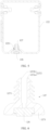
- FIG. 5 is a schematic diagram of connection between the magnetic element 126 and the support body according to some embodiments of this application.
- the magnetic element 126 is mounted at the bottom of the connecting beam 122.
- the "bottom of the connecting beam 122" is a side of the connecting beam 122 close to the battery 110 being inserted into the support 120. Taking a vehicle as an example, the battery 110 is upward inserted into the support 120 from the bottom of the vehicle. Therefore, the bottom of the connecting beam 122 is a side of the connecting beam 122 close to the bottom of the vehicle.
- the battery swapping device 600 replaces the battery below the support 120. Therefore, the magnetic element 126 being provided at the bottom of the connecting beam 122 makes the magnetic element 126 closer to the battery swapping device 600. This helps the positioning apparatus 620 of the battery swapping device 600 to fast detect the magnetic element 126 so as to position the support 120 and the battery swapping device 600.
- FIG. 6 is a schematic diagram of connection between the magnetic element 126 and a connecting element 127 according to some embodiments of this application.
- the support 120 further includes the connecting element 127, where the connecting element 127 is configured to connect the magnetic element 126 and the support body.
- the support body is provided with the mounting hole 1221, where the mounting hole 1221 is configured to accommodate at least part of the connecting element 127.
- a limiting structure 1273 is formed on the connecting element 127, where the limiting structure 1273 is configured to prevent the connecting element 127 from leaving the mounting hole 1221.
- the mounting hole 1221 being configured to accommodate at least part of the connecting element 127 means that the mounting hole 1221 can accommodate part or all of the connecting element 127. Refer to FIG. 5. FIG. 5 shows the case that the mounting hole 1221 accommodates part of the connecting element 127. When the mounting hole 1221 has enough depth, the mounting hole 1221 can accommodate all of the connecting element 127.
- the limiting structure 1273 is a structure configured to prevent the connecting element 127 from leaving the mounting hole 1221, decreasing the risk of the connecting element 127 leaving the mounting hole 1221.
- connection element 127 is conducive to mounting the magnetic element 126 on the support body.
- the limiting structure 1273 is formed on the connecting element 127 such that the connecting element 127 accommodated in the mounting hole 1221 cannot leave the mounting hole 1221, increasing the reliability of connection between the magnetic element 126 and the support body and decreasing the risk of the magnetic element 126 being separated from the support body during use of the electric device body 400.
- the limiting structure 1273 includes a plurality of barbs spaced apart on the connecting element 127 in a direction of the connecting element 127 being inserted into the mounting hole 1221, where the plurality of barbs are at least partly accommodated in the mounting hole 1221.
- the barb is a strip-shaped structure or a needle-shaped structure, where a first end of the barb is connected to the connecting element 127, and a gap is present between a second end of the barb and the connecting element 127.
- the connecting element 127 moves in the opposite direction to the direction of the connecting element 127 being inserted into the mounting hole 1221, the second end of the barb abuts on the hole wall of the mounting hole 1221 or the support body to prevent the connecting element 127 from moving in the opposite direction to the direction of the connecting element 127 being inserted into the mounting hole 1221.
- the barbs have a property of unidirectional passability. Therefore, the barbs provided on the connecting element 127 allow the connecting element 127 to be inserted into the mounting hole 1221 while preventing the connecting element 127 from leaving the mounting hole 1221. This facilitates and simplifies mounting of the connecting element 127 and guarantees the reliability of connection between the connecting element 127 and the support 120 body.
- the limiting structure 1273 is an elastic portion and an abutting portion, where the abutting portion is connected to one side of the connecting element 127 through the elastic portion.
- the abutting portion abuts on the hole wall of the mounting hole 1221 or the support body to prevent the connecting element 127 from moving in the opposite direction to the direction of the connecting element 127 being inserted into the mounting hole 1221.
- the connecting element 127 further includes a head portion 1271 and an extension portion 1272, where the head portion 1271 is connected to one end of the extension portion 1272.
- the extension portion 1272 is configured to be inserted into the mounting hole 1221, and the limiting structure 1273 is provided on the extension portion 1272.
- the head portion 1271 is configured to abut against the support 120 body in the direction of the connecting element 127 being inserted into the mounting hole 1221, and the limiting structure 1273 is configured to prevent the extension portion 1272 from leaving the mounting hole 1221 in an opposite direction to the direction of the connecting element 127 being inserted into the mounting hole 1221.
- the head portion 1271 is of a flat disk shape, and the diameter of the head portion 1271 is greater than that of the mounting hole 1221.
- the head portion 1271 abuts on the support body to prevent the extension portion 1272 from continuing to move in the mounting hole 1221.
- the head portion 1271 is a square plate, and the length of sides of the head portion 1271 is greater than the diameter of the mounting hole 1221, also achieving an abutting-on effect.
- the head portion 1271 is not limited to a specified shape in this application, provided that the head portion can abut against the support body in the direction of the connecting element 127 being inserted into the mounting hole 1221.
- the head portion 1271 and the extension portion 1272 provided and the limiting structure 1273 provided on the extension portion 1272 when the connecting element 127 is inserted, the head portion 1271 can abut against the support body to prevent the connecting element 127 from being over-inserted into the support body or protruding out of the mounting hole 1221.
- the limiting structure 1273 can prevent the extension portion 1272 from leaving the mounting hole 1221 in an opposite direction to the direction of the connecting element 127 being inserted into the mounting hole 1221. In this way, the connecting element 127 is limited in the mounting hole 1221 such that the connecting element 127 cannot leave the mounting hole 1221 or the support 120 body, making a firm connection between the connecting element 127 and the support body.
- the support body is provided with a recess, where the recess is configured for accommodating the head portion 1271.
- Providing the recess for accommodating the head portion 1271 reduces the height of the head portion 1271 protruding from the support body, decreasing the risk of head portion 1271 being damaged due to collision with other structures.
- the extension portion 1272 includes a first arm 1272a and a second arm 1272b that are spaced apart, where the first arm 1272a and the second arm 1272b are both provided with the limiting structure 1273.
- the first arm 1272a is a strip-shaped structure extending in the direction of the connecting element 127 being inserted into the mounting hole 1221.
- the limiting structure 1273 is provided on a side of the first arm 1272a farther away from the second arm 1272b.
- the second arm 1272b is a strip-shaped structure extending in the direction of the connecting element 127 being inserted into the mounting hole 1221.
- the limiting structure 1273 is provided on a side of the second arm 1272b farther away from the first arm 1272a.
- the first arm 1272a and the second arm 1272b are disposed opposite each other, with a space or gap between them.
- the first arm 1272a and the second arm 1272b may slightly deform when bearing a force such that the first arm 1272a and the second arm 1272b approach each other.
- a gap is present between the first arm 1272a and the second arm 1272b.
- the connecting element 127 When the connecting element 127 is inserted into the mounting hole 1221, the first arm 1272a and the second arm 1272b are simultaneously in contact with the hole wall of the mounting hole 1221, and the first arm 1272a and the second arm 1272b can approach each other under the action of a force to reduce the volume of the extension portion 1272, facilitating insertion of the extension portion 1272 into the mounting hole 1221.
- the first arm 1272a and the second arm 1272b reset due to losing the action of a force, and the limiting structures 1273 on the first arm 1272a and the second arm 1272b prevent the extension portion 1272 from leaving the mounting hole 1221.
- At least part of the magnetic element 126 is buried in the connecting element 127.
- the magnetic element 126 being buried in the connecting element 127 means that the magnetic element 126 is pre-buried in the connecting element 127 or is subsequently buried at the connecting element 127 by other means.
- the magnetic element 126 is partly buried at the head portion 1271 of the connecting element 127.
- the magnetic element 126 partly protrudes from the head portion 1271 of the connecting element 127.
- the magnetic element 126 being buried at the connecting element 127 brings better strength and stability of connection between the magnetic element 126 and the connecting element 127, decreasing the risk of the magnetic element 126 leaving the connecting element 127.
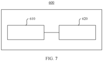
- FIG. 7 is a schematic structural diagram of a battery swapping system according to some embodiments of this application.
- the embodiment of this application provides a battery swapping system used to swap batteries for the foregoing electric device 1000.
- the battery swapping system includes the battery swapping device 600, where the battery swapping device 600 includes an execution mechanism 610 and a positioning apparatus 620, where the positioning apparatus 620 is configured to perform detection for the magnetic element 126 so as to position the battery swapping device 600 and the support 120.
- the execution mechanism 610 is configured to replace the battery 110 of the electric device 1000.
- the execution mechanism 610 is provided with a second positioning element, where the second positioning element is configured to cooperate with the first positioning element 125 provided on the support body, for positioning.
Landscapes
- Engineering & Computer Science (AREA)
- Chemical & Material Sciences (AREA)
- General Chemical & Material Sciences (AREA)
- Mechanical Engineering (AREA)
- Chemical Kinetics & Catalysis (AREA)
- Electrochemistry (AREA)
- Transportation (AREA)
- Aviation & Aerospace Engineering (AREA)
- Power Engineering (AREA)
- Combustion & Propulsion (AREA)
- Life Sciences & Earth Sciences (AREA)
- Sustainable Development (AREA)
- Sustainable Energy (AREA)
- Battery Mounting, Suspending (AREA)
- Electric Propulsion And Braking For Vehicles (AREA)
- Charge And Discharge Circuits For Batteries Or The Like (AREA)
Applications Claiming Priority (2)
| Application Number | Priority Date | Filing Date | Title |
|---|---|---|---|
| CN202122406386.4U CN216886351U (zh) | 2021-09-30 | 2021-09-30 | 一种支架、电池组件、用电设备及换电系统 |
| PCT/CN2022/098231 WO2023050879A1 (zh) | 2021-09-30 | 2022-06-10 | 一种支架、电池组件、用电设备及换电系统 |
Publications (1)
| Publication Number | Publication Date |
|---|---|
| EP4245601A1 true EP4245601A1 (en) | 2023-09-20 |
Family
ID=82195636
Family Applications (1)
| Application Number | Title | Priority Date | Filing Date |
|---|---|---|---|
| EP22874277.1A Pending EP4245601A1 (en) | 2021-09-30 | 2022-06-10 | Support, battery assembly, electric device and battery swapping system |
Country Status (4)
| Country | Link |
|---|---|
| US (1) | US20230322191A1 (zh) |
| EP (1) | EP4245601A1 (zh) |
| CN (1) | CN216886351U (zh) |
| WO (1) | WO2023050879A1 (zh) |
Family Cites Families (9)
| Publication number | Priority date | Publication date | Assignee | Title |
|---|---|---|---|---|
| CN101418760B (zh) * | 2008-11-17 | 2010-12-08 | 江阴林格科技有限公司 | 高压端端置结构分配泵提前器行程传感器 |
| JP6332057B2 (ja) * | 2015-01-26 | 2018-05-30 | 株式会社豊田自動織機 | バッテリ着脱装置 |
| CN105109466B (zh) * | 2015-07-31 | 2017-10-24 | 谢子聪 | 一种基于移动式的电动乘用车动力电池更换的控制方法 |
| CN205621392U (zh) * | 2016-05-20 | 2016-10-05 | 广州正辉装饰材料有限公司 | 组装简易的发光字安装结构 |
| CN111347919A (zh) * | 2016-12-30 | 2020-06-30 | 上海电巴新能源科技有限公司 | 用于更换电动汽车电池的换电平台、换电移动平台及快换系统 |
| CN106515681B (zh) * | 2016-12-30 | 2020-06-19 | 上海电巴新能源科技有限公司 | 换电移动装置和快换系统 |
| CN211280706U (zh) * | 2019-12-05 | 2020-08-18 | 浙江吉智新能源汽车科技有限公司 | 一种可换电动力电池组件及车辆 |
| CN213893285U (zh) * | 2020-09-30 | 2021-08-06 | 奥动新能源汽车科技有限公司 | 电池转运设备的定位装置 |
| CN213768313U (zh) * | 2020-09-30 | 2021-07-23 | 宁德时代新能源科技股份有限公司 | 支架、电池组件及用电设备 |
-
2021
- 2021-09-30 CN CN202122406386.4U patent/CN216886351U/zh active Active
-
2022
- 2022-06-10 EP EP22874277.1A patent/EP4245601A1/en active Pending
- 2022-06-10 WO PCT/CN2022/098231 patent/WO2023050879A1/zh unknown
-
2023
- 2023-06-13 US US18/208,897 patent/US20230322191A1/en active Pending
Also Published As
| Publication number | Publication date |
|---|---|
| WO2023050879A1 (zh) | 2023-04-06 |
| CN216886351U (zh) | 2022-07-05 |
| US20230322191A1 (en) | 2023-10-12 |
Similar Documents
| Publication | Publication Date | Title |
|---|---|---|
| CN113043906B (zh) | 一种换电式纯电动重卡换电系统结构 | |
| EP4245601A1 (en) | Support, battery assembly, electric device and battery swapping system | |
| CN113415171B (zh) | 一种悬浮驱动一体化的磁悬浮系统及悬浮驱动方法 | |
| CN220022493U (zh) | 直线电机、悬架系统和车辆 | |
| JP2012132212A (ja) | 車両輸送船用の表示ポール装置 | |
| CN113103912A (zh) | 一种纯电动重卡换电系统导向机构 | |
| CN106696843B (zh) | 车载平板电脑组件和具有其的车辆 | |
| CN216251407U (zh) | 连接装置及用电装置 | |
| CN116039438A (zh) | 车载动力电池组件以及新能源车 | |
| CN212765729U (zh) | 悬浮牵引装置及磁浮轨道检测装置 | |
| CN215244434U (zh) | 一种纯电动重卡换电系统导向机构 | |
| CN112721720A (zh) | 电池机构、车辆和电池箱安装方法 | |
| CN210609681U (zh) | 辅助支架和振动发声装置组件 | |
| KR20120047587A (ko) | 액화천연가스 저장탱크용 단열구조체 및 이를 포함하는 선박 | |
| CN215521539U (zh) | 快换锁销浮动装置及具有其的车辆 | |
| EP4283174A1 (en) | Connecting structure, battery, and electric device | |
| JP2010029026A (ja) | リニアモータ | |
| CN209402292U (zh) | 一种便于叠放运输的直流牵引电动机 | |
| CN219775531U (zh) | 一种转向灯 | |
| CN217896085U (zh) | 一种用于磁浮交通的整体式永磁轨道结构 | |
| CN219017805U (zh) | 电池的箱体、电池、用电设备和储能系统 | |
| CN219392110U (zh) | 浮动机构、支撑装置及检测设备 | |
| CN216232997U (zh) | 无人机分离式货舱的锁定装置及无人机 | |
| CN220798038U (zh) | 电机、主动悬架和车辆 | |
| CN218908199U (zh) | 一种多类型汽车座椅通用托盘 |
Legal Events
| Date | Code | Title | Description |
|---|---|---|---|
| STAA | Information on the status of an ep patent application or granted ep patent |
Free format text: STATUS: THE INTERNATIONAL PUBLICATION HAS BEEN MADE |
|
| PUAI | Public reference made under article 153(3) epc to a published international application that has entered the european phase |
Free format text: ORIGINAL CODE: 0009012 |
|
| STAA | Information on the status of an ep patent application or granted ep patent |
Free format text: STATUS: REQUEST FOR EXAMINATION WAS MADE |
|
| 17P | Request for examination filed |
Effective date: 20230612 |
|
| AK | Designated contracting states |
Kind code of ref document: A1 Designated state(s): AL AT BE BG CH CY CZ DE DK EE ES FI FR GB GR HR HU IE IS IT LI LT LU LV MC MK MT NL NO PL PT RO RS SE SI SK SM TR |