EP4245226A2 - Mécanisme de libération pour agrafeuse chirurgicale linéaire - Google Patents
Mécanisme de libération pour agrafeuse chirurgicale linéaire Download PDFInfo
- Publication number
- EP4245226A2 EP4245226A2 EP23186181.6A EP23186181A EP4245226A2 EP 4245226 A2 EP4245226 A2 EP 4245226A2 EP 23186181 A EP23186181 A EP 23186181A EP 4245226 A2 EP4245226 A2 EP 4245226A2
- Authority
- EP
- European Patent Office
- Prior art keywords
- arm
- assembly
- jaw
- staple
- latching lever
- Prior art date
- Legal status (The legal status is an assumption and is not a legal conclusion. Google has not performed a legal analysis and makes no representation as to the accuracy of the status listed.)
- Pending
Links
- 230000007246 mechanism Effects 0.000 title description 8
- 239000012636 effector Substances 0.000 claims abstract description 99
- 238000010304 firing Methods 0.000 claims abstract description 76
- 238000005520 cutting process Methods 0.000 description 25
- 238000000034 method Methods 0.000 description 14
- 210000001331 nose Anatomy 0.000 description 14
- 238000005516 engineering process Methods 0.000 description 11
- 230000008878 coupling Effects 0.000 description 10
- 238000010168 coupling process Methods 0.000 description 10
- 238000005859 coupling reaction Methods 0.000 description 10
- 230000008901 benefit Effects 0.000 description 9
- 239000000463 material Substances 0.000 description 9
- 230000007704 transition Effects 0.000 description 8
- 230000004044 response Effects 0.000 description 7
- 238000010276 construction Methods 0.000 description 5
- 230000014509 gene expression Effects 0.000 description 5
- 230000005855 radiation Effects 0.000 description 4
- 230000003872 anastomosis Effects 0.000 description 3
- 230000000712 assembly Effects 0.000 description 3
- 238000000429 assembly Methods 0.000 description 3
- 238000004140 cleaning Methods 0.000 description 3
- 230000002496 gastric effect Effects 0.000 description 3
- 230000004048 modification Effects 0.000 description 3
- 238000012986 modification Methods 0.000 description 3
- 230000037361 pathway Effects 0.000 description 3
- 238000011282 treatment Methods 0.000 description 2
- 241000894006 Bacteria Species 0.000 description 1
- IAYPIBMASNFSPL-UHFFFAOYSA-N Ethylene oxide Chemical compound C1CO1 IAYPIBMASNFSPL-UHFFFAOYSA-N 0.000 description 1
- 239000004775 Tyvek Substances 0.000 description 1
- 229920000690 Tyvek Polymers 0.000 description 1
- 230000006978 adaptation Effects 0.000 description 1
- 239000000853 adhesive Substances 0.000 description 1
- 230000001070 adhesive effect Effects 0.000 description 1
- 230000002452 interceptive effect Effects 0.000 description 1
- 238000002955 isolation Methods 0.000 description 1
- 238000002360 preparation method Methods 0.000 description 1
- 230000001954 sterilising effect Effects 0.000 description 1
- 238000004659 sterilization and disinfection Methods 0.000 description 1
- 238000003466 welding Methods 0.000 description 1
Images


Classifications
-
- A—HUMAN NECESSITIES
- A61—MEDICAL OR VETERINARY SCIENCE; HYGIENE
- A61B—DIAGNOSIS; SURGERY; IDENTIFICATION
- A61B17/00—Surgical instruments, devices or methods, e.g. tourniquets
- A61B17/11—Surgical instruments, devices or methods, e.g. tourniquets for performing anastomosis; Buttons for anastomosis
- A61B17/115—Staplers for performing anastomosis in a single operation
-
- A—HUMAN NECESSITIES
- A61—MEDICAL OR VETERINARY SCIENCE; HYGIENE
- A61B—DIAGNOSIS; SURGERY; IDENTIFICATION
- A61B17/00—Surgical instruments, devices or methods, e.g. tourniquets
- A61B17/068—Surgical staplers, e.g. containing multiple staples or clamps
- A61B17/072—Surgical staplers, e.g. containing multiple staples or clamps for applying a row of staples in a single action, e.g. the staples being applied simultaneously
- A61B17/07207—Surgical staplers, e.g. containing multiple staples or clamps for applying a row of staples in a single action, e.g. the staples being applied simultaneously the staples being applied sequentially
-
- A—HUMAN NECESSITIES
- A61—MEDICAL OR VETERINARY SCIENCE; HYGIENE
- A61B—DIAGNOSIS; SURGERY; IDENTIFICATION
- A61B17/00—Surgical instruments, devices or methods, e.g. tourniquets
- A61B17/068—Surgical staplers, e.g. containing multiple staples or clamps
- A61B17/072—Surgical staplers, e.g. containing multiple staples or clamps for applying a row of staples in a single action, e.g. the staples being applied simultaneously
-
- A—HUMAN NECESSITIES
- A61—MEDICAL OR VETERINARY SCIENCE; HYGIENE
- A61B—DIAGNOSIS; SURGERY; IDENTIFICATION
- A61B17/00—Surgical instruments, devices or methods, e.g. tourniquets
- A61B17/11—Surgical instruments, devices or methods, e.g. tourniquets for performing anastomosis; Buttons for anastomosis
- A61B17/1114—Surgical instruments, devices or methods, e.g. tourniquets for performing anastomosis; Buttons for anastomosis of the digestive tract, e.g. bowels or oesophagus
-
- A—HUMAN NECESSITIES
- A61—MEDICAL OR VETERINARY SCIENCE; HYGIENE
- A61B—DIAGNOSIS; SURGERY; IDENTIFICATION
- A61B17/00—Surgical instruments, devices or methods, e.g. tourniquets
- A61B17/32—Surgical cutting instruments
- A61B17/3205—Excision instruments
-
- A—HUMAN NECESSITIES
- A61—MEDICAL OR VETERINARY SCIENCE; HYGIENE
- A61B—DIAGNOSIS; SURGERY; IDENTIFICATION
- A61B17/00—Surgical instruments, devices or methods, e.g. tourniquets
- A61B17/068—Surgical staplers, e.g. containing multiple staples or clamps
-
- A—HUMAN NECESSITIES
- A61—MEDICAL OR VETERINARY SCIENCE; HYGIENE
- A61B—DIAGNOSIS; SURGERY; IDENTIFICATION
- A61B17/00—Surgical instruments, devices or methods, e.g. tourniquets
- A61B2017/00477—Coupling
-
- A—HUMAN NECESSITIES
- A61—MEDICAL OR VETERINARY SCIENCE; HYGIENE
- A61B—DIAGNOSIS; SURGERY; IDENTIFICATION
- A61B17/00—Surgical instruments, devices or methods, e.g. tourniquets
- A61B17/068—Surgical staplers, e.g. containing multiple staples or clamps
- A61B17/072—Surgical staplers, e.g. containing multiple staples or clamps for applying a row of staples in a single action, e.g. the staples being applied simultaneously
- A61B2017/07214—Stapler heads
- A61B2017/0725—Stapler heads with settable gap between anvil and cartridge, e.g. for different staple heights at different shots
-
- A—HUMAN NECESSITIES
- A61—MEDICAL OR VETERINARY SCIENCE; HYGIENE
- A61B—DIAGNOSIS; SURGERY; IDENTIFICATION
- A61B17/00—Surgical instruments, devices or methods, e.g. tourniquets
- A61B17/068—Surgical staplers, e.g. containing multiple staples or clamps
- A61B17/072—Surgical staplers, e.g. containing multiple staples or clamps for applying a row of staples in a single action, e.g. the staples being applied simultaneously
- A61B2017/07214—Stapler heads
- A61B2017/07271—Stapler heads characterised by its cartridge
-
- A—HUMAN NECESSITIES
- A61—MEDICAL OR VETERINARY SCIENCE; HYGIENE
- A61B—DIAGNOSIS; SURGERY; IDENTIFICATION
- A61B17/00—Surgical instruments, devices or methods, e.g. tourniquets
- A61B17/068—Surgical staplers, e.g. containing multiple staples or clamps
- A61B17/072—Surgical staplers, e.g. containing multiple staples or clamps for applying a row of staples in a single action, e.g. the staples being applied simultaneously
- A61B2017/07214—Stapler heads
- A61B2017/07285—Stapler heads characterised by its cutter
Definitions
- a linear cutting stapler generally includes a first jaw, a second jaw, a lever for clamping the first jaw relative to the second jaw, an anvil associated with either the first jaw or the second jaw, a staple cartridge associated with the jaw opposing the staple anvil, and a firing assembly movable relative to the rest of the linear cutting stapler.
- the first jaw and the second jaw may pivot relative each other in order to grasp tissue between the jaws.
- Staples are arranged in the staple cartridge such that a portion of firing assembly may actuate through the staple cartridge to drive staples out of staple cartridge, through the tissue, and against anvil while also severing tissue captured between the staple cartridge and the staple anvil.
- proximal refers the position of an element closer to the human or robotic operator of the surgical instrument and further away from the surgical end effector of the surgical instrument.
- distal refers to the position of an element closer to the surgical end effector of the surgical instrument and further away from the human or robotic operator of the surgical instrument.
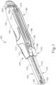
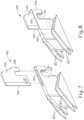
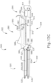
- FIG. 1 depicts an exemplary surgical linear cutting stapler (100) that may be used for any suitable procedure, such as a gastrointestinal anastomosis.
- Linear cutting stapler (100) includes a first portion (102) having a staple cartridge channel (122), a second portion (104) having an anvil channel (130), a staple cartridge assembly (150) that may selectively couple with cartridge channel (122) of first portion (102), and a firing assembly (200).
- first portion (102) and staple cartridge assembly (150) may pivotably couple with second portion (104) to form an end effector (120) capable of clamping, severing, and stapling tissue captured between opposing halves of end effector (120).
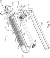
- firing assembly (200) includes an actuating beam (202), a staple sled assembly (160) housed within staple cartridge assembly (150), an actuator (204) (also referred to as a "firing knob"), and a pivot arm (206).
- Actuating beam (202) extends from a distal end (201) to a proximal end (203).
- Actuating beam (202) is slidably housed within first portion (102).
- Pivot arm (206) connects actuator (204) with distal end (201) of actuating beam (202).
- Actuator (204) and pivot arm (206) may pivot from a proximal position (shown in FIG. 1 ) to either lateral side of actuating beam (202) (shown in FIG.
- first portion (102) and second portion (104) define a slot (118) dimensioned to accommodate translation of actuator (204).
- actuating beam (202) is operable to couple with staple sled assembly (160) when staple cartridge assembly (150) is suitably coupled with first portion (102) such that actuator (204) may slide along first side (116) or second side (117) of instrument (100), thereby driving actuating beam (202) and staple sled assembly (160) distally through cartridge assembly (150) to fire instrument (100).
- actuator (204) is configured to pivot to either side (116, 117) of instrument (100) to drive actuating beam (202), this is merely optional, as actuator (204) may slidably couple with first portion (102) or second portion (104) through any means apparent to one having ordinary skill in the art in view of the teachings herein.
- actuator (204) may strictly associate with first side (116) or second side (117) such that actuator (204) may not pivot when end effector (120) is in the fully closed position.
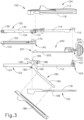
- first portion (102) includes a first proximal frame (110), staple cartridge channel (122), and a latching lever (180).
- First proximal frame (110) extends from a proximal end (103) distally into staple cartridge channel (122).
- first proximal frame (110) and staple cartridge channel (122) are formed integrally so as to define an elongate cartridge channel member having a unitary construction.
- Latching lever (180) is pivotably coupled to either staple cartridge channel (122) or first proximal frame (110) via a pin (182).
- First proximal frame (110) may be coupled with a handle cover (108) configured to promote sufficient grip such that an operator may control instrument (100) while the operator performs a suitable procedure.
- Handle cover (108) may couple with first proximal frame (110) by any suitable means as would be apparent to one having ordinary skill in the art in view of the teachings herein. Alternatively, handle cover (108) may be unitarily coupled with first proximal frame (110) or even omitted.
- First proximal frame (110) defines a channel that slidably houses actuating beam (202) of firing assembly (200).
- Proximal end (103) includes one or more lateral pins, or projections (111).
- Projections (111) are configured to receive grooves (115) of second portion (104) in order to initially pivotably couple first and second portions (102, 104).
- projections (111) are raised from the rest of first proximal frame (110) via a post (107), however this is merely optional.
- projections (111) may include a single pin extending laterally across side walls of first proximal frame (110).
- any suitable means of initially pivotably couplings first portion (102) and second portion (104) may be used as would be apparent to one having ordinary skill in the art in view of the teachings herein.
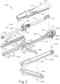
- staple cartridge channel (122) extends distally from first proximal frame (110). As seen in FIG. 2 , staple cartridge channel (122) is dimensioned to selectively couple and decouple with staple cartridge assembly (150). Staple cartridge channel (122) includes a bottom wall (126), and two opposed side walls (124) extending from opposite ends of bottom wall (126). Walls (124, 126) are dimensioned to receive at least a portion of staple cartridge assembly (150), as seen in FIG. 4 . Additionally, side walls (124) include inwardly extending lateral projections (not shown) configured to receive coupling cutouts (140) defined by a proximal end of staple cartridge assembly (150).
- Coupling cutouts (140) may be dimensioned for a snap-fitting or press-fitting with inwardly extending lateral projections (not shown) of side walls (124) such that an operator may selectively attach and detach staple cartridge assembly (150) to staple cartridge channel (122). While coupling cutouts (140) and inwardly extending lateral projections (not shown) are used to selectively couple staple cartridge assembly (150) with staple cartridge channel (122), any other suitable coupling means may be used as would be apparent to one having ordinary skill in the art in view of the teachings herein.
- Side walls (124) of staple cartridge channel (122) also include side flanges (128) each defining a notch or recess (127). Recesses (127) are dimensioned to receive latch projections (131) of second portion (104) when second portion (104) pivots such that end effector (120) is in a fully closed position (as shown in FIG. 10D ) relative to first portion (102).
- latching lever (180) is pivotably coupled to the rest of first portion (102) via pivot pin (182).
- Latching lever (180) includes a proximal extending arm (184) and a distal latch body (188).
- Proximal extending arm (184) may be pivoted about pin (182) toward first proximal frame (110) in order to pivot distal latch body (188) toward staple cartridge channel (122) such that distal latch body (188) may engage and pivot second portion (104) toward first portion (102) to transition end effector (120) from a partially closed position (as shown in FIG. 10C ) to a fully closed position (as shown in FIG. 10D ).
- Proximally extending arm (184) may be coupled with an arm cover (186) to promote sufficient grip such that an operator may grasp arm (184) while the operator performs a suitable procedure.
- Arm cover (186) may be coupled with proximal extending arm (184) by any suitable means as would be apparent to one having ordinary skill in the art in view of the teachings herein.
- arm cover (186) may be unitarily coupled with proximally extending arm (184) or even omitted.
- Distal latch body (188) includes a pair of hooks (189). Distal latch body (188) also defines a corresponding pair of latch cutouts (185) located proximally relative to hooks (189). As will be described is greater detail below, each hook (189) is dimensioned to initially make contact with and then capture a respective latch projection (131) of second portion (104) such that distal latch body (188) may wrap around at least a portion of each latch projection (131) to further pivot second portion (104) toward first portion (102). As will also be described in greater detail below, each latch cutout (185) is dimensioned to receive a respective latch projection (131) when end effector (120) is in the closed position relative to first portion (102).
- staple cartridge assembly (150) includes a cartridge body (152), a pan (154), and a plurality of staple drivers (168), each configured to drive a respective staple (not shown).
- Cartridge body (152) defines a plurality of staple cavities (151), a slot (156), and coupling cutouts (140).
- Staple drivers (168) and respective staples (not shown) are slidably housed within a corresponding staple cavity (151). When first portion (102) and second portion (104) are coupled together, staple cartridge assembly (150) and staple cartridge channel (122) form a portion of end effector (120).
- staple cartridge assembly (150) is configured to house or receive staple sled assembly (160) of firing assembly (200) such that staple sled assembly (160) may actuate through cartridge assembly (150) in order to simultaneously sever and staple tissue captured between the two halves of end effector (120).
- coupling cutouts (140) of cartridge body (152) may be dimensioned for a snap-fitting with inwardly extending lateral projections (not shown) of side walls (124) of staple cartridge channel (122) such that an operator may selectively attach and detach staple cartridge assembly (150) to staple cartridge channel (122).
- Cartridge body (152) includes a distal nose (153). When staple cartridge assembly (150) is properly coupled with cartridge channel (122), distal nose (153) may extend distally from cartridge channel (122) to provide an atraumatic tip.
- cartridge body (152) includes a staple deck (158).
- Staple deck (158) partially defines staple cavities (151) such that staple cavities (151) extend from an interior of cartridge body (152) toward an open end at staple deck (158).
- Staple cavities (151) each house a corresponding staple driver (168) and staple (not shown).
- staple deck (158) partially defines slot (156) that extends from an interior of cartridge body (152) toward an open end at staple deck (158).
- Slot (156) is dimensioned to slidably receive a portion of a sled body (162) and cutting member (164) of staple sled assembly (160) such that cutting member (164) may sever tissue as staple sled assembly (160) slides distally through cartridge body (152).
- Pan (154) may include flexible arms (155). Flexible arms (155) may be configured to engage cartridge body (152) such that pan (154) may couple with cartridge body (152) in a snap-fit or press-fit relationship. Pan (154) may couple with cartridge body (152) after staple drivers (168) and staples (not shown) have been inserted into respective staple cavities (151). Pan (154) may therefore act as a floor for staple drivers (168).
- cartridge body (152) includes a sled assembly housing (170) located near the proximal end of staple cartridge assembly (150).
- Sled assembly housing (170) is configured to initially house staple sled assembly (160) of firing assembly (200).
- Sled assembly housing (170) includes a body (172) defining a cavity (174) having a distally facing opening.
- Body (172) and cavity (174) are dimensioned to house a cutting member (164) of sled assembly (160) prior to firing, therefore acting as a sheath for cutting member (164). When fired, cutting member (164) may exit sled assembly housing (170) via the distally facing opening of cavity (174).
- sled assembly (160) includes a sled body (162) and a cutting member (164).
- Cutting member (164) includes a cutting edge (165) and a lock arm (166).
- Sled body (162) defines a cutout (161) and a slot (163).
- Slot (163) is dimensioned to receive a portion of cutting member (164) such that cutting member (164) and sled body (162) may actuate together.
- Cutting member (164) may couple with sled body (162) via an inference fit with slot (163), through use of adhesives, or any other suitable manner was would be apparent to one having ordinary skill in the art in view of the teachings herein.
- cutting member (164) may couple with sled body (162) though any suitable manner as would be apparent to one having ordinary skill in the art in view of the teachings herein, such as being unitarily connected, welding, etc.
- Cutout (161) is dimensioned to couple with distal end (201) of actuating beam (202) when staple cartridge assembly (150) is properly attached to staple cartridge channel (122). Therefore, when properly coupled, actuating beam (202) may drive sled assembly (160) longitudinally through cartridge body (152). It should be understood that since actuating beam (202) is coupled with sled assembly (160) during exemplary use, actuating beam (202) is also dimensioned to slide within slot (156) defined by cartridge body (152).
- Sled body (162) also includes a plurality of cam surfaces (167) dimensioned to slide longitudinally within respective elongate grooves (not shown) that pass through staple cavities (151) of cartridge body (152).
- cam surfaces (167) are configured to engage and cam against sloped surfaces (169) of staple drivers (168) within staple cavities (151) in order to actuate staple drivers (168) toward staple deck (158).
- Staple drivers (168) then drive corresponding staples (not shown) through staple cavities (151) away from staple deck (158).
- staple sled assembly (160) is configured to couple with the rest of firing assembly (200) when staple cartridge assembly (150) is suitably coupled with staple cartridge channel (122).
- staple sled assembly (160) of firing assembly (200) is associated with cartridge assembly (150) such that after cartridge assembly (150) is used and disposed of, so is staple sled assembly (160). Therefore, when an additional cartridge assembly (150) is loaded into staple cartridge channel (122), a new staple sled assembly (160) will be present.
- staple sled assembly (160) may be fixed or otherwise coupled to the rest of firing assembly (200) such that the same staple sled assembly (160) may be used multiple times with multiple staple cartridge assemblies (150).
- cartridge body (152) would not need a sled assembly housing (170).
- staple sled assembly (160) may be incorporated into either staple cartridge assembly (150), staple cartridge channel (122), or first proximal frame (110) will be apparent to one having ordinary skill in the art in view of the teachings herein.
- second portion (104) of instrument (100) includes a second proximal frame (114), anvil channel (130), latch projections (131), and an anvil plate (134).
- Second proximal frame (114) extends from a proximal end defining grooves (115) in anvil channel (130).
- second proximal frame (114) and anvil channel (130) are formed integrally so as to define an elongate anvil channel member having a unitary construction.
- Second proximal frame (114) may be coupled with a handle cover (112) configured to promote sufficient grip such that an operator may control instrument (100) while the operator performs a suitable procedure.
- Handle cover (112) and second proximal frame (114) may couple with each other by any suitable means as would be apparent to one having ordinary skill in the art in view of the teachings herein.
- handle cover (112) may be unitarily coupled with second proximal frame (114) or even omitted.
- Second proximal frame (114) may also define a channel configured to enable portions of firing assembly (200) to actuate relative to first portion (102) and second portion (104) when end effector (120) is in the fully closed position (as shown in FIG. 10D ).
- Second portion (104) terminates distally in a distal nose (139).
- Distal nose (139) may extend distally from anvil channel (130) to provide an atraumatic tip.
- proximal end of anvil plate (134) defines a recess (179) dimensioned to receive sled assembly housing (170) when first portion (102) and second portion (104) are pivoted toward each other.
- latch projections (131) extend laterally away from anvil channel (130) and are dimensioned to interact with distal latch body (180) to draw anvil plate (134) toward staple cartridge assembly (150).
- Anvil plate (134) defines a plurality of staple forming pockets (132) and a slot (133). Staple forming pockets (132) are positioned along anvil plate (134) such that each staple forming pocket (132) aligns with a corresponding staple cavity (151) when anvil channel (130) is pivoted toward staple cartridge channel (122) to the fully closed position (as shown in FIGS. 1 , 10D , and 11A-B ).
- staples (not shown) are driven through staple cavities (151) away from staple deck (158), through tissue, and against a corresponding staple forming pocket (132) such that staples (not shown) transform from a general" U" shape into a general "B" shape in order to suitably staple tissue.
- Slot (133) is dimensioned to laterally align with slot (156) of staple cartridge assembly (150) when anvil channel (130) is pivoted to the fully closed position (as shown in FIGS. 1 , 10D , 11A-11B ).
- Slot (133) is dimensioned to slidably receive a portion of cutting member (164) as staple sled assembly (160) is driven through staple cartridge assembly (150) such that cutting member (164) may sever tissue captured between anvil surface (134) and staple deck (158) during exemplary use.
- second portion (104) of instrument (100) of the present example further includes a staple height adjustment mechanism (136).
- Adjustment mechanism (136) is operatively coupled with anvil plate (134), for example via one or more camming features (not shown), and includes a pair of user-engageable projections (138).
- Adjustment mechanism (136) is selectively movable relative to anvil channel (130) between two or more longitudinal positions to raise or lower anvil plate (134) relative to anvil channel (130), and thereby adjust a gap distance (or "tissue gap") between anvil plate (134) and staple deck (158) when first and second instrument portions (102, 104) are coupled together in a fully closed position.
- a larger gap distance, and thus a greater staple height, may be provided for stapling tissues of greater thicknesses.
- a smaller gap distance, and thus a smaller staple height may be provided for stapling tissues of lesser thicknesses.
- staple height adjustment mechanism (136) is merely optional and may be omitted in other examples.
- Surgical linear cutting stapler may be further configured and operable in accordance with one or more teachings of U.S. Pat. 7,905,381, entitled “Surgical Stapling Instrument with Cutting Member Arrangement,” issued March 15, 2011 ; U.S. Pat. No. 7,954,686, entitled “Surgical Stapler with Apparatus for Adjusting Staple Height,” issued June 7, 2011 ; U.S. Pat. No. 8,348,129, entitled “Surgical Stapler Having A Closure Mechanism,” issued January 8, 2013 ; and U.S. Pat. No. 8,789,740, entitled “Linear Cutting and Stapling Device with Selectively Disengageable Cutting Member,” issued July 29, 2014 .
- the disclosure of each of these references is incorporated by reference herein.
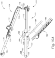
- FIGS. 10A-11B show an exemplary use of instrument (100).
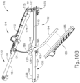
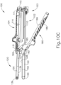
- FIGS. 10A-10D show an exemplary coupling of first portion (102) with second portion (104), and pivoting first portion (102) and second portion (104) such that end effector (120) transitions from an open position ( FIG. 10B ), to a partially closed position ( FIG. 10C ), and finally to a fully closed position ( FIG. 10D ).
- FIGS. 11A-11B show an exemplary firing of instrument (100) when end effector (120) is in a fully closed position.
- FIG. 10A shows first portion (102) completely detached from second portion (204). Additionally, staple cartridge assembly (150) is suitably attached to staple cartridge channel (122) in accordance with the description above.
- an operator may desire to place lumens of tissue over and past distal noses (139, 153) of second portion (104) and cartridge assembly (150), respectively, such that lumens of tissue are suitably associated with both anvil plate (134) and cartridge assembly (150).
- an operator may align grooves (115) of second portion (104) with corresponding lateral projections (111) of first portion (102) in preparation of initially pivotally coupling first portion (102) with second portion (104).
- an operator may insert lateral projections (111) into corresponding grooves (115) such that first portion (102) and second portion (104) are pivotally coupled, but end effector (120) is in an open position.
- First portion (102) and second portion (104) may pivot relative to each other about the axis defined by lateral projections (111).
- latching lever (180) is not in contact with any portion of second portion (104). Additionally, latching lever (180) is in an open position such that proximal extending arm (184) is pivoted away from first proximal frame (110).
- an operator may initially pivot anvil channel (130) and anvil plate (134) toward cartridge channel (122) and staple cartridge assembly (150), and partially pivot latching lever (180) such that hooks (189) initially contact latch projections (131).
- end effector (120) is in the partially closed position.
- an operator may further rotate proximal extending arm (184) toward first proximal frame (110), causing distal latch body (188) to drive latch projections (131) along the surfaces of distal latch body (188) toward latch cutouts (185).
- latch projections (131) are driven toward latch cutouts (185), anvil channel (130) and anvil plate (134) rotate further toward cartridge channel (122) and staple cartridge assembly (150) such that end effector (120) is in the closed position. Additionally, latch projections (131) are also driven toward recesses (127) of staple cartridge channel (122) such that each latch projection (131) is encompassed by a combination of the respective latch cutout (185) and recess (127), effectively latching end effector (120) into the closed position.
- Latch cutouts (185) and recesses (127) may be dimensioned to interface with latch projections (131) while end effector (120) is in the fully closed position such that latch projections (131) and pivot pin (182) extend along a vertical axis (VA) that is substantially perpendicular with the longitudinal axis of instrument (100). This may provide a mechanical advantage for an enhanced closure force during suitable use.
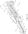
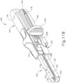
- FIGS. 11A-11B show an exemplary firing of instrument (100) with end effector (120) in the fully closed position.
- an operator may pivot actuator (204) to either side (116, 117) of instrument (100).
- actuator (204) has been pivoted to second side (117) of instrument (100).
- operator may push actuator (204) distally toward end effector (120) within slot (118), such that actuating beam (202) and sled (160) are fired, thereby stapling and severing tissue captured between stapling deck (158) and anvil plate (134) in accordance with the description above.
- an operator may pull actuator (204) proximally back to the position shown in FIG.
- an operator may pivot latching lever (180) about pin (182) in a first direction in order to pivot end effector (120) from a partially closed position (as shown in FIG. 10C ) to a fully closed position (as shown in FIG. 10D ).
- an operator may also pivot latching lever (180) about pin (182) in a second, opposite, direction in order to open end effector (120) from the fully closed position (as shown in FIG. 10D ) back to the partially closed position (as shown in FIG. 10C ).
- end effector (120) may be difficult to open end effector (120) by directly grasping proximal extending arm (184) to pivot latching lever (180). End effector (120) may lock-up in the fully closed position such that it requires a great amount of force to initially pivot latching lever (180) out of the fully closed position. Such difficulty may be increased when latch projections (131) and pivot pin (182) are dimensioned to extend along a common vertical axis (VA) thereby providing a mechanical advantage for enhanced closure force as described above.
- VA vertical axis
- release assembly may help urge latching lever (180) to initially pivot end effector (120) out of the fully closed position such that an operator may then more easily open end effector (120) by directly grasping and rotating proximal extending arm (184) afterwards.
- Examples of alternative release assemblies are described in greater detail below.
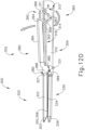
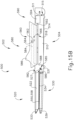
- FIGS. 12A-12D show an exemplary alternative instrument (300) that may be used in place of instrument (100) described above.
- Instrument (300) is substantially similar to instrument (100) described above, with differences elaborated below.
- Instrument (300) includes a first portion (302) having a staple cartridge channel (322), a second portion (304) having an anvil channel (330), a staple cartridge assembly (350) that may selectively couple with cartridge channel (322) of first portion (302), a firing assembly (390), and a release assembly (360).
- First portion (302), second portion (304), staple cartridge assembly (350), and firing assembly (390) are substantially similar to first portion (102), second portion (104), staple cartridge assembly (150), and firing assembly (200) described above, respectively, with difference described below. Therefore, first portion (302) and staple cartridge assembly (350) may pivotably couple with second portion (304) to form an end effector (320) that is capable of clamping, severing, and stapling tissue captured between opposing halves of end effector (320).
- release assembly (360) is configured to help urge latching lever (380) to initially pivot end effector (320) out of the fully closed position toward a partially closed position.
- Firing assembly (390) includes an actuating beam (392), an actuator (394), and a staple sled assembly (not shown), substantially similar to actuating beam (202), actuator (204), and staple sled assembly (160) described above, respectively, with differences described below.
- actuator (394) may not pivot to either lateral side of instrument (300). However, this is merely optional, as actuator (394) may be configured substantially similar to actuator (204) described above; or similar to any other actuator that would be apparent to one having ordinary skill in the art in view of the teachings herein.
- First portion (302) includes a first proximal frame (310), staple cartridge channel (322), and a latching lever (380), which are substantially similar to first proximal frame (110), staple cartridge channel (122), and latching lever (180), described above, respectively, with differences elaborated below.
- first proximal frame (310) and staple cartridge channel (322) are formed integrally so as to define an elongate cartridge channel member having a unitary construction.
- Latching lever (380) is pivotably coupled to either staple cartridge channel (322) or first proximal frame (310) via a pin (382).
- First proximal frame (310) defines a channel that slidably houses actuating beam (392) of firing assembly (390). While first proximal frame (110) of instrument (100) includes one or more lateral pins, or projections (111) that are configured to be received in groove (115) of second portion (104); first proximal frame (310) of the current example defines grooves (315) that are configured to house lateral pins or projections (311) of second portion (304). Grooves (315) are configured to house pins (311) of second portion (304) in order to initially pivotably couple first and second portions (302, 304).
- first portion (102) and second portion (104) Rather than both first portion (102) and second portion (104) defining lateral slot (118) while end effector (120) is in the fully closed position; first portion (302) of the current example defines lateral slot (318) alone, which defines a pathway for actuator (394) to travel.
- staple cartridge channel (322) is dimensioned to selectively couple and decouple with staple cartridge assembly (350).
- Cartridge assembly (350) includes a staple deck (358) and a distal nose (353) which are substantially similar to staple deck (158) and distal nose (153) described above.
- Staple cartridge channel (322) also defines notches or recesses (327) which are substantially similar to notches or recesses (127) described above. Therefore, recesses (327) are dimensioned to receive latch projections (331) of second portion (304) when second portion (304) pivots such that end effector (320) is in a fully closed position (as shown in FIGS. 12B-12C ) relative to first portion (302).
- Latching lever (380) includes a proximal extending arm (384) and a distal latch body (388), which are substantially similar to proximal extending arm (184) and distal latch body (188) described above, respectively. Therefore, distal latch body (388) includes a pair of hooks (389) which are substantially similar to hooks (189) described above. Additionally, distal latch body (388) also defines a corresponding pair of latch cutouts (385), which are substantially similar to latch cutouts (185) described above.
- Second portion (304) of instrument (300) includes a second proximal frame (314), anvil channel (330), latch projections (331), and an anvil plate (334), which are substantially similar to second proximal frame (114), anvil channel (130), latch projections (131) and anvil plate (134) describe above, with differences described herein.
- Second portion (304) terminates distally in a distal nose (339), which extends distally from anvil channel (330) to provide an atraumatic tip.
- release assembly (360) is configured to help urge latching lever (380) to initially pivot end effector (320) out of a fully closed position toward a partially closed position.
- Release assembly (360) includes a rotating body (364) pivotably coupled to first proximal frame (310) via a pivot pin (362). Therefore, rotating body (364) may rotate relative to proximal frame (310) about an axis defined by pivot pin (362).
- Rotating body (364) includes a first leg (366) and a second leg (368). First leg (366) is dimensioned to abut against actuator (394) as actuator (394) travels toward a proximal position along the path defined by lateral slot (318).
- Second leg (368) is dimensioned to abut against proximal extending arm (384) without interfering with translation of actuator (394). Second leg (368) may be partially housed within the channel defined by first proximal frame (310) or any other suitable location at would be apparent to one having ordinary skill in the art in view of the teachings herein.
- rotating body (364) is configured to pivot in response to proximal translation of actuator (394), thereby initially urging latching lever (380) to pivot such that end effector (320) transitions from the fully closed position toward the partially closed position. Afterwards, an operator may more easily open end effector (320) by directly grasping and rotating proximal extending arm (384).
- FIGS. 12A-12D show an exemplary use of instrument (300) to grasp tissue between staple deck (358) and anvil plate (334) in order to simultaneously sever and staple grasped tissue.
- FIG. 12A shows end effector (320) in the partially closed position and firing assembly (390) in a first position. End effector (320) may transition to the partially closed position in accordance with the teachings above. At this point, tissue may be located between the confines of staple deck (358) and anvil plate (334). As best shown between FIGS.
- an operator may further rotate proximal extending arm (384) toward first proximal frame (310), causing distal latch body (388) to drive latch projections (331) along the surfaces of distal latch body (388) toward latch cutouts (385).
- latch projections (331) are driven toward latch cutouts (385)
- anvil channel (330) and anvil plate (334) rotate further toward cartridge channel (322) and staple cartridge assembly (350) such that end effector (320) is in the fully closed position.
- latch projections (331) are also driven toward recesses (327) of staple cartridge channel (322) such that each latch projection (331) is encompassed by a combination of the respective latch cutout (385) and recess (327), effectively latching end effector (320) into the fully closed position.
- end effector (320) grasping tissue the operator may translate actuator (394) of firing assembly (390) distally in order to simultaneously sever and staple tissue captured between staple deck (358) and anvil plate (334), in accordance with the description above.
- the operator may wish re-grasp tissue prior to actuating firing assembly (390) to simultaneously severe and staple tissue.
- Second leg (368) may be dimensioned to abut against a portion of proximal extending arm (384) a sufficient distance away from pivot pin (382) to provide a mechanical advantage in urging latching lever (380) to open end effector (320). This mechanical advantage may help initially open, or unlock, end effector (320) from the fully closed position.
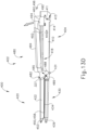
- FIGS. 13A-13D show an exemplary alternative instrument (400) that may be used in place of instrument (100) described above.
- Instrument (400) is substantially similar to instrument (100) described above, with differences elaborated below.
- Instrument (400) includes a first portion (402) having a staple cartridge channel (422), a second portion (404) having an anvil channel (430), a staple cartridge assembly (450) that may selectively couple with cartridge channel (422) of first portion (402), a firing assembly (490), and a release assembly (460).
- First portion (402), second portion (404), staple cartridge assembly (450), and firing assembly (490) are substantially similar to first portion (102), second portion (104), staple cartridge assembly (150), and firing assembly (200) described above, respectively, with difference described below. Therefore, first portion (402) and staple cartridge assembly (450) may pivotably couple with second portion (404) to form an end effector (420) capable of clamping, severing, and stapling tissue captured between opposing halves of end effector (420).
- release assembly (460) is configured to help urge latching lever (480) to initially pivot end effector (420) out of the fully closed position toward a partially closed position.
- Firing assembly (490) includes an actuating beam (492), an actuator (494), and a staple sled assembly (not shown), substantially similar to actuating beam (202), actuator (204), and staple sled assembly (160) described above, respectively, with differences described below.
- actuator (494) may not pivot to either lateral side of instrument (400). However, this is merely optional, as actuator (494) may be configured substantially similar to actuator (204) described above; or similar to any other actuator that would be apparent to one having ordinary skill in the art in view of the teachings herein.
- First portion (402) includes a first proximal frame (410), staple cartridge channel (422), and a latching lever (480), which are substantially similar to first proximal frame (110), staple cartridge channel (122), and latching lever (180), described above, respectively, with differences elaborated below.
- first proximal frame (410) and staple cartridge channel (422) are formed integrally so as to define an elongate cartridge channel member having a unitary construction.
- Latching lever (480) is pivotably coupled to either staple cartridge channel (422) or first proximal frame (410) via a pin (482).
- First proximal frame (410) defines a channel that slidably houses actuating beam (492) of firing assembly (490). While first proximal frame (110) of instrument (100) includes one or more lateral pins, or projections (111) that are configured to be received in groove (115) of second portion (104); first proximal frame (410) of the current example defines grooves (415) that are configured to house lateral pins or projections (411) of second portion (404). Grooves (415) are configured to house pins (411) of second portion (404) in order to initially pivotably couple first and second portions (402, 404).
- first portion (402) of the current example defines lateral slot (418) alone, which defines a pathway for actuator (494) to travel.
- staple cartridge channel (422) is dimensioned to selectively couple and decouple with staple cartridge assembly (450).
- Cartridge assembly (450) includes a staple deck (458) and a distal nose (453) which are substantially similar to staple deck (158) and distal nose (153) described above.
- Staple cartridge channel (422) also defines notches or recesses (427) which are substantially similar to notches or recesses (127) described above. Therefore, recesses (427) are dimensioned to receive latch projections (431) of second portion (404) when second portion (404) pivots such that end effector (420) is in a fully closed position relative to first portion (402) (as shown in FIGS. 13B-13C ).
- Latching lever (480) includes a proximal extending arm (484) and a distal latch body (488), which are substantially similar to proximal extending arm (184) and distal latch body (188) described above, respectively. Therefore, distal latch body (488) includes a pair of hooks (489) that are substantially similar to hooks (189) described above. Additionally, distal latch body (488) also defines a corresponding pair of latch cutouts (485), which are substantially similar to latch cutouts (185) described above.
- Second portion (404) of instrument (400) includes a second proximal frame (414), anvil channel (430), latch projections (431), and an anvil plate (434), which are substantially similar to second proximal frame (114), anvil channel (130), latch projections (131) and anvil plate (134) describe above, with differences described herein.
- Second portion (404) terminates distally in a distal nose (439), which extends distally from anvil channel (430) to provide an atraumatic tip.
- release assembly (460) is configured to help urge latching lever (480) to initially pivot end effector (420) out of a fully closed position toward a partially closed position.
- Release assembly (360) includes a cam surface (462) extending proximally from the open end of proximal extending arm (484).
- Cam surface (463) is dimensioned to abut against a corresponding cam surface (496) of actuator (494) as actuator (494) travels toward a proximal position along the path defined by lateral slot (418).
- proximal translation of actuator (494) will initially pivot latching lever (480) open such that end effector (420) transitions from the fully closed position toward the partially closed position. Afterwards, an operator may more easily open end effector (420) by directly grasping and rotating proximal extending arm (484).
- FIGS. 13A-13D show an exemplary use of instrument (400) to grasp tissue between staple deck (458) and anvil plate (434) in order to simultaneously sever and staple grasped tissue.
- FIG. 13A shows end effector (420) in the partially closed position and firing assembly (490) in a first position. End effector (420) may transition to the partially closed position in accordance with the teachings above. At this point, tissue may be located between the confines of staple deck (458) and anvil plate (434). As best shown between FIGS.
- an operator may further rotate proximal extending arm (484) toward first proximal frame (410), causing distal latch body (488) to drive latch projections (431) along the surfaces of distal latch body (488) toward latch cutouts (485).
- latch projections (431) are driven toward latch cutouts (485)
- anvil channel (430) and anvil plate (434) rotate further toward cartridge channel (422) and staple cartridge assembly (450) such that end effector (420) is in the closed position.
- latch projections (431) are also driven toward recesses (427) of staple cartridge channel (422) such that each latch projection (431) is encompassed by a combination of the respective latch cutout (485) and recess (427), effectively latching end effector (420) into the closed position.
- the operator may translate actuator (494) of firing assembly (490) distally in order to simultaneously sever and staple tissue captured between staple deck (458) and anvil plate (434), in accordance with the description above.
- the operator may wish re-grasp tissue prior to actuating firing assembly (490) to simultaneously severe and staple tissue.
- actuator (494) may slide against cam surface (462) of release assembly (460), which may help rotate latching lever (480) in an angular direction about pivot pin (482) such that end effector (420) is urged toward the partially closed position.
- camming surfaces (462, 496) urging end effector (420) away from the fully closed position toward the partially closed position, the operator may more easily open end effector (420) by directly grasping and rotating proximal extending arm (484).
- Camming surface (462) of release assembly (460) may be located along proximally extending arm (484) a sufficient distance away from pivot pin (482) to provide a mechanical advantage in urging latching lever (480) to open end effector (420). This mechanical advantage may help initially open, or unlock, end effector (420) from the fully closed position.
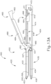
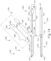
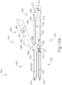
- FIGS. 14-15C show an exemplary alternative instrument (500) that may be used in place of instrument (100) described above.
- Instrument (500) is substantially similar to instrument (100) described above, with differences elaborated below.
- Instrument (500) includes a first portion (502) having a staple cartridge channel (522), a second portion (504) having an anvil channel (530), a staple cartridge assembly (550) that may selectively couple with cartridge channel (522) of first portion (502), a firing assembly (590), and a release assembly (560).
- First portion (502), second portion (504), staple cartridge assembly (550), and firing assembly (590) are substantially similar to first portion (102), second portion (104), staple cartridge assembly (150), and firing assembly (200) described above, respectively, with difference described below. Therefore, first portion (502) and staple cartridge assembly (550) may pivotably couple with second portion (504) to form an end effector (520) that is capable of clamping, severing, and stapling tissue captured between opposing halves of end effector (520).
- release assembly (560) is configured to help urge latching lever (580) to initially pivot end effector (520) from a fully closed position to a partially closed position.
- Firing assembly (590) includes an actuating beam (592), an actuator (594), and a staple sled assembly (not shown), substantially similar to actuating beam (202), actuator (204), and staple sled assembly (160) described above, respectively, with differences described below.
- actuator (594) may not pivot to either lateral side of instrument (500). However, this is merely optional, as actuator (594) may be configured substantially similar to actuator (204) described above, or any other actuator that would be apparent to one having ordinary skill in the art in view of the teachings herein.
- First portion (502) includes a first proximal frame (510), staple cartridge channel (522), a latching lever (580), and an arm cover (586), which are substantially similar to first proximal frame (110), staple cartridge channel (122), latching lever (180), and arm cover (186) described above, respectively, with differences elaborated below.
- first proximal frame (510) and staple cartridge channel (522) are formed integrally so as to define an elongate cartridge channel member having a unitary construction.
- Latching lever (580) is pivotably coupled to either staple cartridge channel (522) or first proximal frame (510) via a pin (582).
- arm cover (586) is slidably coupled to latching lever (580) such that arm cover (586) may at least partially actuate relative to latching lever (580).
- First proximal frame (510) defines a channel that slidably houses actuating beam (592) of firing assembly (590). While first proximal frame (110) of instrument (100) includes one or more lateral pins, or projections (111) that were configured to be received in groove (115) of second portion (104); first proximal frame (510) of the current example defines grooves (515) that are configured to house lateral pins or projections (511) of second portion (504). Grooves (515) are configured to house pins (511) of second portion (504) in order to initially pivotably couple first and second portions (502, 504).
- first portion (502) of the current example defines lateral slot (518) alone, which defines a pathway for actuator (594) to travel.
- staple cartridge channel (522) is dimensioned to selectively couple and decouple with staple cartridge assembly (550).
- Cartridge assembly (550) includes a staple deck (558) and a distal nose (553) that are substantially similar to staple deck (158) and distal nose (153) described above.
- Staple cartridge channel (522) also defines notches or recesses (527) that are substantially similar to notches or recesses (127) described above. Therefore, recesses (527) are dimensioned to receive latch projections (531) of second portion (504) when second portion (504) pivots such that end effector (520) is in a fully closed position relative to first portion (502) (as shown in FIG. 15B ).
- Latching lever (580) includes a proximal extending arm (584) and a distal latch body (588), which are substantially similar to proximal extending arm (184) and distal latch body (188) described above, respectively, with differences elaborated below. Therefore, distal latch body (588) includes a pair of hooks (589) that are substantially similar to hooks (189) described above. Additionally, distal latch body (588) also defines a corresponding pair of latch cutouts (585), which are substantially similar to latch cutouts (185) described above.
- Second portion (504) of instrument (500) includes a second proximal frame (514), anvil channel (530), latch projections (531), and an anvil plate (534), which are substantially similar to second proximal frame (114), anvil channel (130), latch projections (131) and anvil plate (134) describe above, with differences described herein.
- Second portion (504) terminates distally in a distal nose (539), which extends distally from anvil channel (530) to provide an atraumatic tip.
- release assembly (560) is configured to help urge latching lever (580) to initially pivot end effector (520) out of a fully closed position toward a partially closed position.
- Release assembly (560) includes pivoting body (562) pivotably coupled to proximal extending arm (584) via a pivot pin (564), and a cam pin (566) associated with arm cover (586).
- Rotating body (564) is positioned on proximal extending arm (584) such that rotating body (564) is directly adjacent to first proximal frame (510) when end effector (520) is in the fully closed position.
- arm cover (586) is slidably coupled to proximal extending arm (584) such that arm cover (586) may actuate relative to proximal extending arm (584).
- Cam pin (566) is positioned on proximal extending arm (584) such that actuation of arm cover (586) relative to arm (584) causes cam pin (566) is cam against pivoting body (562), thereby driving rotation of pivoting body (562) about rotation pin (564).
- arm cover (586) relative to arm (586) will rotate pivoting body (562) about pivot pin (562) such that pivoting body (5620 abuts against first proximal frame (510), thereby driving rotation of latching lever (580) open such that end effector (520) transitions from the fully closed position toward the partially closed position.
- an operator may more easily open end effector (520) by directly grasping and rotating proximal extending arm (584).
- FIGS. 15A-15C show an exemplary use of instrument (500) to grasp tissue between staple deck (558) and anvil plate (534) in order to simultaneously sever and staple grasped tissue.
- FIG. 15A shows end effector (520) in the partially closed position and firing assembly (590) in a first position. End effector (520) may transition to the partially closed position in accordance with the teachings above. At this point, tissue may be located between the confines of staple deck (558) and anvil plate (534). As best shown between FIGS.
- an operator may further rotate proximal extending arm (584) toward first proximal frame (510), causing distal latch body (588) to drive latch projections (531) along the surfaces of distal latch body (588) toward latch cutouts (585).
- latch projections (531) are driven toward latch cutouts (585)
- anvil channel (530) and anvil plate (534) rotate further toward cartridge channel (522) and staple cartridge assembly (550) such that end effector (520) is in the closed position.
- latch projections (531) are also driven toward recesses (527) of staple cartridge channel (522) such that each latch projection (531) is encompassed by a combination of the respective latch cutout (585) and recess (527), effectively latching end effector (520) into the closed position.
- end effector (52) grasping tissue the operator may translate actuator (584) of firing assembly 9590) distally in order to simultaneously sever and staple tissue captured between staple deck (558) and anvil plate (534), in accordance with the description above.
- the operator may wish to re-grasp tissue prior to actuating firing assembly (590) to simultaneously severe and staple tissue.
- Rotating body (562) may be located along proximally extending arm (584) a sufficient distance away from pivot pin (582) to provide a mechanical advantage in urging latching lever (580) to open end effector (520). This mechanical advantage may help initially open, or unlock, end effector (520) from the fully closed position.
- An apparatus comprising: (a) a handle assembly, wherein the handle assembly comprises: (i) a first arm, (ii) a second arm, wherein the second arm is configured to pivotably couple with the first arm at a proximal pivot location, and (iii) a latching lever pivotably coupled with the first arm at a distal pivot location; (b) an end effector, wherein the end effector comprises: (i) a first jaw extending distally from the first arm, and (ii) a second jaw extending distally from the second arm, wherein the second jaw is configured to pivot relative to the first jaw between an open configuration, a partially closed configuration, and a fully closed configuration, wherein the latching lever is configured engage the second arm or the second jaw to pivot the second jaw from the partially closed configuration toward the fully closed configuration; (c) a firing assembly configured to sever tissue captured between the first jaw and the second jaw in the fully closed configuration; and (d) a release assembly configured to urge the latching lever away from the first arm
- Example 1 The apparatus of Example 1, wherein the first jaw is configured to receive a staple cartridge assembly housing a plurality of staples.
- Example 2 The apparatus of Example 2, wherein the staple cartridge assembly comprises a staple sled assembly.
- the firing assembly comprises an actuator configured to translate relative to the first handle and the second handle.
- Example 5 The apparatus of Example 5, wherein the firing assembly further comprises a rotating body pivotally coupled to either the first handle or the second handle.
- Example 6 wherein the rotating body comprises a first leg and a second leg, wherein the first leg is configured to abut against the actuator to pivot the rotating body, wherein the second leg is configured to urge the latching lever away from the first arm in response to the actuator pivoting the rotating body.
- the release assembly comprises a camming surface extending from the latching lever, wherein the actuator is configured to abut against the camming to urge the latching lever away from the first arm.
- Example 9 The apparatus of Example 9, wherein the release assembly comprises a body pivotably attached to the latching lever.
- Example 10 wherein the arm cover comprises a camming pin configured to pivot the body relative to the latching lever in response to movement of the arm cover relative to the latching lever.
- proximal pivot location comprises a transverse pin and a groove.
- Example 12 wherein the transverse pin is associated with the first arm, wherein the second arm defines the groove.
- An apparatus comprising: (a) a first portion comprising: (i) a first handle, and (ii) a first jaw portion extending distally from the first handle; (b) a second portion comprising: (i) a second handle, (ii) a second jaw extending distally from the second handle, and (iii) a latching projection, wherein the second portion is configured to pivotably couple with the first portion at a proximal location; (c) a latching lever pivotably coupled with the first portion, wherein the latching lever is configured to engage the latching projection to pivot the first jaw and the second jaw from a partially closed configuration toward a fully closed configuration; (d) a firing assembly configured to sever tissue between the first jaw and the second jaw in the fully closed position; and (e) a release assembly configured to urge the latching lever away from the first portion to pivot the second jaw and the first jaw from the fully closed configuration toward the partially closed configuration.
- Example 17 The apparatus of Example 17, wherein the release assembly comprises a rotating body, wherein the firing assembly comprises an actuator, wherein the actuator is configured to pivot the rotating body the urge the latching lever away from the first portion.
- An apparatus comprising: (a) a first portion comprising: (i) a first handle, and (ii) a first jaw portion extending distally from the first handle; (b) a second portion comprising: (i) a second handle, (ii) a second jaw extending distally from the second handle, and (iii) a latching projection, wherein the second portion is configured to pivotably couple with the first portion at a proximal location in an open configuration; (c) a latching lever pivotably coupled with the first portion, wherein the latching lever is configured to pivot the first jaw and the second jaw from a partially closed configuration toward a fully closed configuration; and (d) a release assembly configured actuate relative to the latching lever in order to urge the latching lever away from the first portion to pivot the second jaw and the first jaw from the fully closed configuration toward the partially closed configuration.
- any one or more of the teachings, expressions, embodiments, examples, etc. described herein may be combined with any one or more of the teachings, expressions, embodiments, examples, etc. described in U.S. App. No. [Atty. Ref. END7969USNP], entitled “Release Mechanism for Linear Surgical Stapler,” filed on even date herewith; U.S. App. No. [Atty. Ref. END7970USNP], entitled “Lockout Assembly for Linear Surgical Stapler,” filed on even date herewith; U.S. App. No. [Atty. Ref.
- Versions of the devices described above may have application in conventional medical treatments and procedures conducted by a medical professional, as well as application in robotic-assisted medical treatments and procedures.
- various teachings herein may be readily incorporated into a robotic surgical system such as the DAVINCI TM system by Intuitive Surgical, Inc., of Sunnyvale, California.
- Versions described above may be designed to be disposed of after a single use, or they can be designed to be used multiple times. Versions may, in either or both cases, be reconditioned for reuse after at least one use. Reconditioning may include any combination of the steps of disassembly of the device, followed by cleaning or replacement of particular pieces, and subsequent reassembly. In particular, some versions of the device may be disassembled, and any number of the particular pieces or parts of the device may be selectively replaced or removed in any combination. Upon cleaning and/or replacement of particular parts, some versions of the device may be reassembled for subsequent use either at a reconditioning facility, or by a operator immediately prior to a procedure.
- reconditioning of a device may utilize a variety of techniques for disassembly, cleaning/replacement, and reassembly. Use of such techniques, and the resulting reconditioned device, are all within the scope of the present application.
- versions described herein may be sterilized before and/or after a procedure.
- the device is placed in a closed and sealed container, such as a plastic or TYVEK bag.
- the container and device may then be placed in a field of radiation that can penetrate the container, such as gamma radiation, x-rays, or high-energy electrons.
- the radiation may kill bacteria on the device and in the container.
- the sterilized device may then be stored in the sterile container for later use.
- a device may also be sterilized using any other technique known in the art, including but not limited to beta or gamma radiation, ethylene oxide, or steam.
Landscapes
- Health & Medical Sciences (AREA)
- Life Sciences & Earth Sciences (AREA)
- Surgery (AREA)
- Heart & Thoracic Surgery (AREA)
- Engineering & Computer Science (AREA)
- Biomedical Technology (AREA)
- Nuclear Medicine, Radiotherapy & Molecular Imaging (AREA)
- Medical Informatics (AREA)
- Molecular Biology (AREA)
- Animal Behavior & Ethology (AREA)
- General Health & Medical Sciences (AREA)
- Public Health (AREA)
- Veterinary Medicine (AREA)
- Physiology (AREA)
- Surgical Instruments (AREA)
Applications Claiming Priority (2)
| Application Number | Priority Date | Filing Date | Title |
|---|---|---|---|
| US15/889,363 US10631866B2 (en) | 2018-02-06 | 2018-02-06 | Release mechanism for linear surgical stapler |
| EP19155568.9A EP3520714B1 (fr) | 2018-02-06 | 2019-02-05 | Mécanisme de libération pour agrafeuse chirurgicale linéaire |
Related Parent Applications (1)
| Application Number | Title | Priority Date | Filing Date |
|---|---|---|---|
| EP19155568.9A Division EP3520714B1 (fr) | 2018-02-06 | 2019-02-05 | Mécanisme de libération pour agrafeuse chirurgicale linéaire |
Publications (2)
| Publication Number | Publication Date |
|---|---|
| EP4245226A2 true EP4245226A2 (fr) | 2023-09-20 |
| EP4245226A3 EP4245226A3 (fr) | 2023-12-06 |
Family
ID=65324268
Family Applications (2)
| Application Number | Title | Priority Date | Filing Date |
|---|---|---|---|
| EP19155568.9A Active EP3520714B1 (fr) | 2018-02-06 | 2019-02-05 | Mécanisme de libération pour agrafeuse chirurgicale linéaire |
| EP23186181.6A Pending EP4245226A3 (fr) | 2018-02-06 | 2019-02-05 | Mécanisme de libération pour agrafeuse chirurgicale linéaire |
Family Applications Before (1)
| Application Number | Title | Priority Date | Filing Date |
|---|---|---|---|
| EP19155568.9A Active EP3520714B1 (fr) | 2018-02-06 | 2019-02-05 | Mécanisme de libération pour agrafeuse chirurgicale linéaire |
Country Status (7)
| Country | Link |
|---|---|
| US (2) | US10631866B2 (fr) |
| EP (2) | EP3520714B1 (fr) |
| JP (1) | JP7395492B2 (fr) |
| CN (1) | CN111885969B (fr) |
| BR (1) | BR112020016086A2 (fr) |
| MX (1) | MX2020008298A (fr) |
| WO (1) | WO2019155300A1 (fr) |
Families Citing this family (23)
| Publication number | Priority date | Publication date | Assignee | Title |
|---|---|---|---|---|
| US10863988B2 (en) | 2017-11-29 | 2020-12-15 | Intuitive Surgical Operations, Inc. | Surgical instrument with lockout mechanism |
| US10631866B2 (en) | 2018-02-06 | 2020-04-28 | Ethicon Llc | Release mechanism for linear surgical stapler |
| US11517312B2 (en) | 2018-02-12 | 2022-12-06 | Intuitive Surgical Operations, Inc. | Surgical instrument with lockout mechanism |
| US10898187B2 (en) | 2018-08-13 | 2021-01-26 | Ethicon Llc | Firing system for linear surgical stapler |
| USD913495S1 (en) * | 2018-08-13 | 2021-03-16 | Ethicon Llc | Linear surgical stapler |
| US10905419B2 (en) | 2018-10-11 | 2021-02-02 | Ethicon Llc | Closure assembly for linear surgical stapler |
| WO2020131290A1 (fr) | 2018-12-21 | 2020-06-25 | Intuitive Surgical Operations, Inc. | Ensembles articulation pour instruments chirurgicaux |
| WO2020131692A1 (fr) | 2018-12-21 | 2020-06-25 | Intuitive Surgical Operations, Inc. | Instruments chirurgicaux comprenant des mécanismes permettant d'identifier et/ou de désactiver des cartouches d'agrafeuse |
| US11944301B2 (en) | 2018-12-21 | 2024-04-02 | Intuitive Surgical Operations, Inc. | Surgical instruments having a reinforced staple cartridge |
| WO2020214258A1 (fr) | 2019-04-15 | 2020-10-22 | Intuitive Surgical Operations, Inc. | Cartouche d'agrafes pour instrument chirurgical |
| US11166715B2 (en) | 2019-05-13 | 2021-11-09 | Cilag Gmbh International | Actuator support structure for surgical stapler |
| US11464508B2 (en) | 2019-05-13 | 2022-10-11 | Cilag Gmbh International | Actuator retainer for surgical stapler |
| EP3975875A4 (fr) | 2019-05-31 | 2023-02-01 | Intuitive Surgical Operations, Inc. | Cartouche d'agrafes pour instrument chirurgical |
| USD954949S1 (en) | 2019-08-09 | 2022-06-14 | Cilag Gmbh International | Retainer for surgical staple cartridge |
| USD955575S1 (en) | 2019-08-09 | 2022-06-21 | Cilag Gmbh International | Staple cartridge assembly for linear surgical stapler |
| US11229433B2 (en) | 2019-08-09 | 2022-01-25 | Cilag Gmbh International | Linear surgical stapler |
| USD956230S1 (en) | 2019-08-09 | 2022-06-28 | Cilag Gmbh International | Staple cartridge assembly for linear surgical stapler |
| WO2021076371A1 (fr) * | 2019-10-18 | 2021-04-22 | Intuitive Surgical Operations, Inc. | Instrument chirurgical avec mâchoires ajustables |
| US11219454B2 (en) | 2020-05-29 | 2022-01-11 | Cilag Gmbh International | Pin trap mechanism for surgical linear cutter |
| US11224425B2 (en) | 2020-05-29 | 2022-01-18 | Cilag Gmbh International | Surgical linear cutter wishbone separation mechanism with detent |
| WO2022233036A1 (fr) * | 2021-05-07 | 2022-11-10 | Covidien Lp | Dispositifs auxiliaires pour appareil d'agrafage |
| US11937812B2 (en) | 2021-09-30 | 2024-03-26 | Cilag Gmbh International | Lockout feature for linear surgical stapler cartridge |
| WO2023242702A1 (fr) | 2022-06-14 | 2023-12-21 | Cilag Gmbh International | Agrafeuse chirurgicale linéaire |
Citations (3)
| Publication number | Priority date | Publication date | Assignee | Title |
|---|---|---|---|---|
| US7905381B2 (en) | 2008-09-19 | 2011-03-15 | Ethicon Endo-Surgery, Inc. | Surgical stapling instrument with cutting member arrangement |
| US8348129B2 (en) | 2009-10-09 | 2013-01-08 | Ethicon Endo-Surgery, Inc. | Surgical stapler having a closure mechanism |
| US8789740B2 (en) | 2010-07-30 | 2014-07-29 | Ethicon Endo-Surgery, Inc. | Linear cutting and stapling device with selectively disengageable cutting member |
Family Cites Families (147)
| Publication number | Priority date | Publication date | Assignee | Title |
|---|---|---|---|---|
| US960300A (en) | 1908-07-16 | 1910-06-07 | Victor Fischer | Wire-stitching instrument. |
| US3078465A (en) | 1959-09-09 | 1963-02-26 | Bobrov Boris Sergueevitch | Instrument for stitching gastric stump |
| GB927936A (en) | 1959-10-02 | 1963-06-06 | Boris Sergeevich Bobrov | An instrument for making anastomoses |
| US3079606A (en) | 1960-01-04 | 1963-03-05 | Bobrov Boris Sergeevich | Instrument for placing lateral gastrointestinal anastomoses |
| US3317105A (en) | 1964-03-25 | 1967-05-02 | Niiex Khirurgicheskoi Apparatu | Instrument for placing lateral intestinal anastomoses |
| US3315863A (en) | 1965-07-06 | 1967-04-25 | United States Surgical Corp | Medical instrument |
| US3490675A (en) | 1966-10-10 | 1970-01-20 | United States Surgical Corp | Instrument for placing lateral gastrointestinal anastomoses |
| SU566574A1 (ru) | 1975-05-04 | 1977-07-30 | Всесоюзный научно-исследовательский и испытательный институт медицинской техники | Аппарат дл наложени линейного скобочного шва на органы и ткани |
| SU599799A1 (ru) | 1975-12-26 | 1978-04-05 | Всесоюзный научно-исследовательский и испытательный институт медицинской техники | Хирургический сшивающий аппарат |
| US4241861A (en) | 1977-12-20 | 1980-12-30 | Fleischer Harry N | Scissor-type surgical stapler |
| SU886897A1 (ru) | 1978-12-25 | 1981-12-07 | Всесоюзный Научно-Исследовательский Институт Медицинской Техники | Хирургический аппарат дл наложени боковых желудочнокишечных анастомозов |
| US4429695A (en) | 1980-02-05 | 1984-02-07 | United States Surgical Corporation | Surgical instruments |
| AU534210B2 (en) | 1980-02-05 | 1984-01-12 | United States Surgical Corporation | Surgical staples |
| USD272852S (en) | 1980-12-19 | 1984-02-28 | United States Surgical Corporation | Linear anastomosis stapler |
| USD272851S (en) | 1981-01-09 | 1984-02-28 | United States Surgical Corporation | Linear anastomosis stapler |
| SU1183082A1 (ru) | 1983-08-19 | 1985-10-07 | Всесоюзный научно-исследовательский и испытательный институт медицинской техники | Хирургический сшивающий аппарат |
| US4610383A (en) | 1983-10-14 | 1986-09-09 | Senmed, Inc. | Disposable linear surgical stapler |
| US4633874A (en) | 1984-10-19 | 1987-01-06 | Senmed, Inc. | Surgical stapling instrument with jaw latching mechanism and disposable staple cartridge |
| US4605001A (en) | 1984-10-19 | 1986-08-12 | Senmed, Inc. | Surgical stapling instrument with dual staple height mechanism |
| US4608981A (en) | 1984-10-19 | 1986-09-02 | Senmed, Inc. | Surgical stapling instrument with staple height adjusting mechanism |
| US4633861A (en) | 1984-10-19 | 1987-01-06 | Senmed, Inc. | Surgical stapling instrument with jaw clamping mechanism |
| USD285836S (en) | 1985-01-07 | 1986-09-23 | Senmed, Inc. | Surgical stapler |
| US4869415A (en) | 1988-09-26 | 1989-09-26 | Ethicon, Inc. | Energy storage means for a surgical stapler |
| JPH02121645A (ja) | 1988-10-31 | 1990-05-09 | Matsutani Seisakusho Co Ltd | 医療用ステープルとその製造方法 |
| US4892244A (en) | 1988-11-07 | 1990-01-09 | Ethicon, Inc. | Surgical stapler cartridge lockout device |
| US5188274A (en) * | 1989-01-23 | 1993-02-23 | Moeinzadeh Manssour H | Semi-disposable surgical stapler |
| US4955959A (en) | 1989-05-26 | 1990-09-11 | United States Surgical Corporation | Locking mechanism for a surgical fastening apparatus |
| US5505363A (en) | 1989-05-26 | 1996-04-09 | United States Surgical Corporation | Surgical staples with plated anvils |
| US5156614A (en) | 1990-09-17 | 1992-10-20 | United States Surgical Corporation | Apparatus for applying two-part surgical fasteners |
| US5653373A (en) | 1990-09-17 | 1997-08-05 | United States Surgical Corporation | Arcuate apparatus for applying two-part surgical fasteners |
| US5129570A (en) | 1990-11-30 | 1992-07-14 | Ethicon, Inc. | Surgical stapler |
| US5141144A (en) | 1990-12-18 | 1992-08-25 | Minnesota Mining And Manufacturing Company | Stapler and firing device |
| WO1992010976A1 (fr) | 1990-12-18 | 1992-07-09 | Minnesota Mining And Manufacturing Company | Dispositif de securite pour cartouche d'agrafeuse chirurgicale |
| US5083695A (en) | 1990-12-18 | 1992-01-28 | Minnesota Mining And Manufacturing Company | Stapler and firing device |
| US5065929A (en) | 1991-04-01 | 1991-11-19 | Ethicon, Inc. | Surgical stapler with locking means |
| US5221036A (en) | 1991-06-11 | 1993-06-22 | Haruo Takase | Surgical stapler |
| US5173133A (en) | 1991-07-23 | 1992-12-22 | United States Surgical Corporation | Method for annealing stapler anvils |
| US5395034A (en) * | 1991-11-07 | 1995-03-07 | American Cyanamid Co. | Linear surgical stapling instrument |
| US5180092A (en) * | 1992-02-05 | 1993-01-19 | Lawrence Crainich | Linear surgical stapling instrument |
| US5364003A (en) | 1993-05-05 | 1994-11-15 | Ethicon Endo-Surgery | Staple cartridge for a surgical stapler |
| US5415334A (en) | 1993-05-05 | 1995-05-16 | Ethicon Endo-Surgery | Surgical stapler and staple cartridge |
| US5542594A (en) | 1993-10-06 | 1996-08-06 | United States Surgical Corporation | Surgical stapling apparatus with biocompatible surgical fabric |
| US5452837A (en) | 1994-01-21 | 1995-09-26 | Ethicon Endo-Surgery, Inc. | Surgical stapler with tissue gripping ridge |
| US5465895A (en) | 1994-02-03 | 1995-11-14 | Ethicon Endo-Surgery, Inc. | Surgical stapler instrument |
| JPH0833642A (ja) | 1994-02-25 | 1996-02-06 | Ethicon Endo Surgery Inc | 外科用ステープラのための改良アンビル承口 |
| US5489058A (en) | 1994-05-02 | 1996-02-06 | Minnesota Mining And Manufacturing Company | Surgical stapler with mechanisms for reducing the firing force |
| US5551622A (en) | 1994-07-13 | 1996-09-03 | Yoon; Inbae | Surgical stapler |
| US5507426A (en) | 1994-08-05 | 1996-04-16 | United States Surgical Corporation | Apparatus for applying surgical fasteners |
| US5636779A (en) | 1994-12-13 | 1997-06-10 | United States Surgical Corporation | Apparatus for applying surgical fasteners |
| US5988479A (en) | 1994-12-13 | 1999-11-23 | United States Surgical Corporation | Apparatus for applying surgical fasteners |
| US5718359A (en) | 1995-08-14 | 1998-02-17 | United States Of America Surgical Corporation | Surgical stapler with lockout mechanism |
| CA2188738A1 (fr) | 1995-10-27 | 1997-04-28 | Lisa W. Heaton | Agrafeuse chirurgicale possedant des unites de chargement interchangeables |
| US5651491A (en) | 1995-10-27 | 1997-07-29 | United States Surgical Corporation | Surgical stapler having interchangeable loading units |
| US5673842A (en) | 1996-03-05 | 1997-10-07 | Ethicon Endo-Surgery | Surgical stapler with locking mechanism |
| US5785232A (en) | 1996-04-17 | 1998-07-28 | Vir Engineering | Surgical stapler |
| US5752965A (en) | 1996-10-21 | 1998-05-19 | Bio-Vascular, Inc. | Apparatus and method for producing a reinforced surgical fastener suture line |
| US5878938A (en) * | 1997-08-11 | 1999-03-09 | Ethicon Endo-Surgery, Inc. | Surgical stapler with improved locking mechanism |
| US6099551A (en) | 1998-03-12 | 2000-08-08 | Shelhigh, Inc. | Pericardial strip and stapler assembly for dividing and sealing visceral tissues and method of use thereof |
| US6206903B1 (en) | 1999-10-08 | 2001-03-27 | Intuitive Surgical, Inc. | Surgical tool with mechanical advantage |
| ES2312476T3 (es) | 2000-10-13 | 2009-03-01 | Tyco Healthcare Group Lp | Aparato de aplicacion de grapas quirurgicas. |
| US7334717B2 (en) * | 2001-10-05 | 2008-02-26 | Tyco Healthcare Group Lp | Surgical fastener applying apparatus |
| WO2003079909A2 (fr) | 2002-03-19 | 2003-10-02 | Tyco Healthcare Group, Lp | Appareil d'application d'element d'attache chirurgical |
| US20040267310A1 (en) | 2000-10-20 | 2004-12-30 | Racenet David C | Directionally biased staple and anvil assembly for forming the staple |
| ES2529325T3 (es) | 2001-10-05 | 2015-02-19 | Covidien Lp | Método de ajuste de aparato de grapado quirúrgico |
| AU2003226050A1 (en) | 2002-04-11 | 2003-10-27 | Tyco Healthcare Group, Lp | Surgical stapling apparatus including an anvil and cartridge each having cooperating mating surfaces |
| WO2003094745A1 (fr) | 2002-05-10 | 2003-11-20 | Tyco Healthcare Group, Lp | Dispositif d'agrafage electrochirurgical |
| DE60335360D1 (de) | 2002-05-10 | 2011-01-27 | Tyco Healthcare | Chirurgisches klammergerät mit einer anordnung zum aufbringen eines wundverschlussmaterials |
| DE60309018T2 (de) | 2002-05-10 | 2007-05-03 | Tyco Healthcare Group Lp, Norwalk | Gerät zum setzen von wundklammern sowie wunddichtungsmasse |
| AU2003234551A1 (en) | 2002-05-13 | 2003-11-11 | Tyco Healthcare Group, Lp | Surgical stapler and disposable loading unit having different size staples |
| EP1507572B1 (fr) | 2002-05-17 | 2007-01-10 | Tyco Healthcare Group Lp | Applicateur de matière de fermeture de plaie |
| EP1897503B1 (fr) | 2002-10-04 | 2010-12-08 | Tyco Healthcare Group, LP | Agrafeur chirurgical doté d'une articulation universelle et pré-clampage des tissus |
| US7296722B2 (en) | 2003-10-17 | 2007-11-20 | Tyco Healthcare Group Lp | Surgical fastener applying apparatus with controlled beam deflection |
| US7210609B2 (en) | 2004-07-30 | 2007-05-01 | Tools For Surgery, Llc | Stapling apparatus having a curved anvil and driver |
| US7121446B2 (en) | 2004-12-13 | 2006-10-17 | Niti Medical Technologies Ltd. | Palm-size surgical stapler for single hand operation |
| US20060180633A1 (en) | 2005-02-17 | 2006-08-17 | Tyco Healthcare Group, Lp | Surgical staple |
| US7288098B2 (en) | 2005-04-14 | 2007-10-30 | Ethicon Endo-Surgery, Inc. | Force limiting mechanism for medical instrument |
| US7722610B2 (en) | 2005-06-02 | 2010-05-25 | Tyco Healthcare Group Lp | Multiple coil staple and staple applier |
| US7717312B2 (en) | 2005-06-03 | 2010-05-18 | Tyco Healthcare Group Lp | Surgical instruments employing sensors |
| US8679154B2 (en) | 2007-01-12 | 2014-03-25 | Ethicon Endo-Surgery, Inc. | Adjustable compression staple and method for stapling with adjustable compression |
| US8038046B2 (en) | 2006-05-19 | 2011-10-18 | Ethicon Endo-Surgery, Inc. | Electrical surgical instrument with optimized power supply and drive |
| US7815092B2 (en) | 2005-07-27 | 2010-10-19 | Power Medical Interventions, Llc | Staple pocket arrangement for surgical stapler |
| US7401721B2 (en) | 2005-08-15 | 2008-07-22 | Tyco Healthcare Group Lp | Surgical stapling instruments including a cartridge having multiple staple sizes |
| US7398908B2 (en) | 2005-08-15 | 2008-07-15 | Tyco Healthcare Group Lp | Surgical stapling instruments including a cartridge having multiple staple sizes |
| US8579178B2 (en) | 2005-08-15 | 2013-11-12 | Covidien Lp | Surgical stapling instruments including a cartridge having multiple staples sizes |
| US7407075B2 (en) | 2005-08-15 | 2008-08-05 | Tyco Healthcare Group Lp | Staple cartridge having multiple staple sizes for a surgical stapling instrument |
| US7407078B2 (en) | 2005-09-21 | 2008-08-05 | Ehthicon Endo-Surgery, Inc. | Surgical stapling instrument having force controlled spacing end effector |
| US7472815B2 (en) | 2005-09-21 | 2009-01-06 | Ethicon Endo-Surgery, Inc. | Surgical stapling instruments with collapsible features for controlling staple height |
| US7641091B2 (en) | 2005-10-04 | 2010-01-05 | Tyco Healthcare Group Lp | Staple drive assembly |
| US7635074B2 (en) | 2005-10-04 | 2009-12-22 | Tyco Healthcare Group Lp | Staple drive assembly |
| US7845537B2 (en) | 2006-01-31 | 2010-12-07 | Ethicon Endo-Surgery, Inc. | Surgical instrument having recording capabilities |
| US7422139B2 (en) | 2006-01-31 | 2008-09-09 | Ethicon Endo-Surgery, Inc. | Motor-driven surgical cutting fastening instrument with tactile position feedback |
| US20110295295A1 (en) | 2006-01-31 | 2011-12-01 | Ethicon Endo-Surgery, Inc. | Robotically-controlled surgical instrument having recording capabilities |
| WO2007112059A2 (fr) | 2006-03-23 | 2007-10-04 | Edrich Health Technologies , Inc. | Agrafeuses anastomotiques vasculaires |
| US7278563B1 (en) | 2006-04-25 | 2007-10-09 | Green David T | Surgical instrument for progressively stapling and incising tissue |
| US8409244B2 (en) | 2007-04-16 | 2013-04-02 | Intuitive Surgical Operations, Inc. | Tool with end effector force limiter |
| US20100133317A1 (en) | 2006-09-29 | 2010-06-03 | Shelton Iv Frederick E | Motor-Driven Surgical Cutting And Fastening Instrument with Tactile Position Feedback |
| US8220690B2 (en) | 2006-09-29 | 2012-07-17 | Ethicon Endo-Surgery, Inc. | Connected surgical staples and stapling instruments for deploying the same |
| US8708210B2 (en) | 2006-10-05 | 2014-04-29 | Covidien Lp | Method and force-limiting handle mechanism for a surgical instrument |
| US7845535B2 (en) | 2006-10-06 | 2010-12-07 | Tyco Healthcare Group Lp | Surgical instrument having a plastic surface |
| EP2073719B1 (fr) | 2006-10-26 | 2017-05-03 | Covidien LP | Dispositif avec des alliages à mémoire de forme pour une fixation de renfort |
| US7490749B2 (en) | 2007-03-28 | 2009-02-17 | Ethicon Endo-Surgery, Inc. | Surgical stapling and cutting instrument with manually retractable firing member |
| US7832611B2 (en) | 2007-05-16 | 2010-11-16 | The Invention Science Fund I, Llc | Steerable surgical stapler |
| US7810691B2 (en) | 2007-05-16 | 2010-10-12 | The Invention Science Fund I, Llc | Gentle touch surgical stapler |
| US8062330B2 (en) | 2007-06-27 | 2011-11-22 | Tyco Healthcare Group Lp | Buttress and surgical stapling apparatus |
| US8636939B2 (en) | 2007-11-06 | 2014-01-28 | Covidien Lp | Mold for actuation sled |
| US7954685B2 (en) | 2007-11-06 | 2011-06-07 | Tyco Healthcare Group Lp | Articulation and firing force mechanisms |
| US8727199B2 (en) | 2008-01-03 | 2014-05-20 | Covidien Lp | Surgical stapler |
| US7766209B2 (en) | 2008-02-13 | 2010-08-03 | Ethicon Endo-Surgery, Inc. | Surgical stapling instrument with improved firing trigger arrangement |
| US8453908B2 (en) * | 2008-02-13 | 2013-06-04 | Ethicon Endo-Surgery, Inc. | Surgical stapling instrument with improved firing trigger arrangement |
| US8231040B2 (en) | 2008-04-14 | 2012-07-31 | Tyco Healthcare Group Lp | Variable compression surgical fastener cartridge |
| US20090255974A1 (en) | 2008-04-14 | 2009-10-15 | Tyco Healthcare Group Lp | Single loop surgical fastener apparatus for applying variable compression |
| US8028884B2 (en) | 2008-04-22 | 2011-10-04 | Tyco Healthcare Group Lp | Cartridge for applying varying amounts of tissue compression |
| US9016541B2 (en) | 2008-05-09 | 2015-04-28 | Covidien Lp | Varying tissue compression with an anvil configuration |
| US8464922B2 (en) | 2008-05-09 | 2013-06-18 | Covidien Lp | Variable compression surgical fastener cartridge |
| US8007513B2 (en) | 2008-06-12 | 2011-08-30 | Ethicon Endo-Surgery, Inc. | Partially reusable surgical stapler |
| US8308043B2 (en) | 2009-05-19 | 2012-11-13 | Covidien Lp | Recognition of interchangeable component of a device |
| US8257634B2 (en) | 2009-10-06 | 2012-09-04 | Tyco Healthcare Group Lp | Actuation sled having a curved guide member and method |
| US8496154B2 (en) | 2009-10-08 | 2013-07-30 | Covidien Lp | Pair of double staple pusher in triple row stapler |
| US8152041B2 (en) | 2009-10-14 | 2012-04-10 | Tyco Healthcare Group Lp | Varying tissue compression aided by elastic members |
| US8418907B2 (en) | 2009-11-05 | 2013-04-16 | Covidien Lp | Surgical stapler having cartridge with adjustable cam mechanism |
| US8267300B2 (en) | 2009-12-30 | 2012-09-18 | Ethicon Endo-Surgery, Inc. | Dampening device for endoscopic surgical stapler |
| US9750502B2 (en) | 2010-10-01 | 2017-09-05 | Covidien Lp | Surgical stapling device for performing circular anastomosis and surgical staples for use therewith |
| US9289209B2 (en) | 2011-06-09 | 2016-03-22 | Covidien Lp | Surgical fastener applying apparatus |
| US9451959B2 (en) | 2011-06-09 | 2016-09-27 | Covidien Lp | Surgical fastener applying apparatus |
| US9271728B2 (en) * | 2011-06-09 | 2016-03-01 | Covidien Lp | Surgical fastener applying apparatus |
| US9561030B2 (en) | 2011-06-14 | 2017-02-07 | Changzhou Kangdi Medical Stapler Co., Ltd. | Surgical staple and staple pocket for forming kidney-shaped staple |
| US9763891B2 (en) | 2011-07-22 | 2017-09-19 | The General Hospital Corporation | Therapeutic nanoparticles and methods of use thereof |
| US9155537B2 (en) * | 2011-08-08 | 2015-10-13 | Covidien Lp | Surgical fastener applying apparatus |
| US9724095B2 (en) * | 2011-08-08 | 2017-08-08 | Covidien Lp | Surgical fastener applying apparatus |
| JP2015506753A (ja) | 2012-01-18 | 2015-03-05 | コヴィディエン リミテッド パートナーシップ | 外科用ファスナー適用装置 |
| US10299815B2 (en) | 2012-01-19 | 2019-05-28 | Covidien Lp | Surgical instrument with clam releases mechanism |
| US9119617B2 (en) | 2012-03-16 | 2015-09-01 | Ethicon, Inc. | Clamping devices for dispensing surgical fasteners into soft media |
| WO2013166115A1 (fr) * | 2012-05-02 | 2013-11-07 | Ethicon Endo-Surgery, Inc. | Dispositif électro-chirurgical pour découper et coaguler |
| CN103263282B (zh) | 2013-05-02 | 2016-02-17 | 苏州天臣国际医疗科技有限公司 | 直线切割吻合器 |
| AU2013403915A1 (en) | 2013-11-04 | 2016-04-28 | Covidien Lp | Surgical fastener applying apparatus |
| EP3065646A1 (fr) | 2013-11-04 | 2016-09-14 | Covidien LP | Appareil d'application d'agrafes chirurgicales |
| US11083491B2 (en) | 2014-12-09 | 2021-08-10 | Medtronic, Inc. | Extravascular implant tools utilizing a bore-in mechanism and implant techniques using such tools |
| US10687819B2 (en) * | 2018-02-06 | 2020-06-23 | Ethicon Llc | Clamping mechanism for linear surgical stapler |
| US10667818B2 (en) | 2018-02-06 | 2020-06-02 | Ethicon Llc | Lockout assembly for linear surgical stapler |
| US10874398B2 (en) | 2018-02-06 | 2020-12-29 | Ethicon Llc | Firing lever assembly for linear surgical stapler |
| US10932781B2 (en) | 2018-02-06 | 2021-03-02 | Ethicon Llc | Features to align and close linear surgical stapler |
| US10631866B2 (en) | 2018-02-06 | 2020-04-28 | Ethicon Llc | Release mechanism for linear surgical stapler |
| US10898197B2 (en) * | 2018-02-06 | 2021-01-26 | Ethicon Llc | Releasable coupling features for proximal portions of linear surgical stapler |
| US11033266B2 (en) * | 2018-08-13 | 2021-06-15 | Cilag Gmbh International | Decoupling mechanism for linear surgical stapler |
| US11278285B2 (en) * | 2018-08-13 | 2022-03-22 | Cilag GbmH International | Clamping assembly for linear surgical stapler |
| US10905419B2 (en) * | 2018-10-11 | 2021-02-02 | Ethicon Llc | Closure assembly for linear surgical stapler |
| US11219454B2 (en) * | 2020-05-29 | 2022-01-11 | Cilag Gmbh International | Pin trap mechanism for surgical linear cutter |
-
2018
- 2018-02-06 US US15/889,363 patent/US10631866B2/en active Active
-
2019
- 2019-01-16 WO PCT/IB2019/050356 patent/WO2019155300A1/fr active Application Filing
- 2019-01-16 JP JP2020549659A patent/JP7395492B2/ja active Active
- 2019-01-16 CN CN201980020610.9A patent/CN111885969B/zh active Active
- 2019-01-16 MX MX2020008298A patent/MX2020008298A/es unknown
- 2019-01-16 BR BR112020016086-5A patent/BR112020016086A2/pt unknown
- 2019-02-05 EP EP19155568.9A patent/EP3520714B1/fr active Active
- 2019-02-05 EP EP23186181.6A patent/EP4245226A3/fr active Pending
-
2020
- 2020-03-31 US US16/836,262 patent/US11439398B2/en active Active
Patent Citations (4)
| Publication number | Priority date | Publication date | Assignee | Title |
|---|---|---|---|---|
| US7905381B2 (en) | 2008-09-19 | 2011-03-15 | Ethicon Endo-Surgery, Inc. | Surgical stapling instrument with cutting member arrangement |
| US7954686B2 (en) | 2008-09-19 | 2011-06-07 | Ethicon Endo-Surgery, Inc. | Surgical stapler with apparatus for adjusting staple height |
| US8348129B2 (en) | 2009-10-09 | 2013-01-08 | Ethicon Endo-Surgery, Inc. | Surgical stapler having a closure mechanism |
| US8789740B2 (en) | 2010-07-30 | 2014-07-29 | Ethicon Endo-Surgery, Inc. | Linear cutting and stapling device with selectively disengageable cutting member |
Also Published As
| Publication number | Publication date |
|---|---|
| EP3520714A1 (fr) | 2019-08-07 |
| US10631866B2 (en) | 2020-04-28 |
| US20190239881A1 (en) | 2019-08-08 |
| JP2021517835A (ja) | 2021-07-29 |
| WO2019155300A1 (fr) | 2019-08-15 |
| CN111885969A (zh) | 2020-11-03 |
| US11439398B2 (en) | 2022-09-13 |
| BR112020016086A2 (pt) | 2020-12-15 |
| US20200289120A1 (en) | 2020-09-17 |
| MX2020008298A (es) | 2020-12-07 |
| CN111885969B (zh) | 2024-05-24 |
| JP7395492B2 (ja) | 2023-12-11 |
| EP3520714B1 (fr) | 2023-07-19 |
| EP3520714C0 (fr) | 2023-07-19 |
| EP4245226A3 (fr) | 2023-12-06 |
Similar Documents
| Publication | Publication Date | Title |
|---|---|---|
| US11439398B2 (en) | Release mechanism for linear surgical stapler | |
| EP3520713B1 (fr) | Mécanisme de serrage pour agrafeuse chirurgicale linéaire | |
| EP3520712B1 (fr) | Ensemble de verrouillage pour agrafeuse chirurgicale linéaire | |
| US20210251631A1 (en) | Features to align and close linear surgical stapler | |
| US10874398B2 (en) | Firing lever assembly for linear surgical stapler | |
| US10898197B2 (en) | Releasable coupling features for proximal portions of linear surgical stapler | |
| CN109661201B (zh) | 外科缝合器 | |
| US11224425B2 (en) | Surgical linear cutter wishbone separation mechanism with detent | |
| US20210369272A1 (en) | Separation mechanism for surgical linear cutter |
Legal Events
| Date | Code | Title | Description |
|---|---|---|---|
| PUAI | Public reference made under article 153(3) epc to a published international application that has entered the european phase |
Free format text: ORIGINAL CODE: 0009012 |
|
| STAA | Information on the status of an ep patent application or granted ep patent |
Free format text: STATUS: THE APPLICATION HAS BEEN PUBLISHED |
|
| AC | Divisional application: reference to earlier application |
Ref document number: 3520714 Country of ref document: EP Kind code of ref document: P |
|
| AK | Designated contracting states |
Kind code of ref document: A2 Designated state(s): AL AT BE BG CH CY CZ DE DK EE ES FI FR GB GR HR HU IE IS IT LI LT LU LV MC MK MT NL NO PL PT RO RS SE SI SK SM TR |
|
| PUAL | Search report despatched |
Free format text: ORIGINAL CODE: 0009013 |
|
| AK | Designated contracting states |
Kind code of ref document: A3 Designated state(s): AL AT BE BG CH CY CZ DE DK EE ES FI FR GB GR HR HU IE IS IT LI LT LU LV MC MK MT NL NO PL PT RO RS SE SI SK SM TR |
|
| RIC1 | Information provided on ipc code assigned before grant |
Ipc: A61B 17/072 20060101AFI20231031BHEP |