EP4243435A2 - Plenoptische kamera mit höherer auflösung unter verwendung einer kontrollierbaren doppelbrechenden schicht - Google Patents
Plenoptische kamera mit höherer auflösung unter verwendung einer kontrollierbaren doppelbrechenden schicht Download PDFInfo
- Publication number
- EP4243435A2 EP4243435A2 EP23184051.3A EP23184051A EP4243435A2 EP 4243435 A2 EP4243435 A2 EP 4243435A2 EP 23184051 A EP23184051 A EP 23184051A EP 4243435 A2 EP4243435 A2 EP 4243435A2
- Authority
- EP
- European Patent Office
- Prior art keywords
- rays
- images
- state
- image
- plenoptic
- Prior art date
- Legal status (The legal status is an assumption and is not a legal conclusion. Google has not performed a legal analysis and makes no representation as to the accuracy of the status listed.)
- Withdrawn
Links
Images


Classifications
-
- H—ELECTRICITY
- H04—ELECTRIC COMMUNICATION TECHNIQUE
- H04N—PICTORIAL COMMUNICATION, e.g. TELEVISION
- H04N23/00—Cameras or camera modules comprising electronic image sensors; Control thereof
- H04N23/95—Computational photography systems, e.g. light-field imaging systems
- H04N23/951—Computational photography systems, e.g. light-field imaging systems by using two or more images to influence resolution, frame rate or aspect ratio
-
- H—ELECTRICITY
- H04—ELECTRIC COMMUNICATION TECHNIQUE
- H04N—PICTORIAL COMMUNICATION, e.g. TELEVISION
- H04N13/00—Stereoscopic video systems; Multi-view video systems; Details thereof
- H04N13/20—Image signal generators
- H04N13/204—Image signal generators using stereoscopic image cameras
- H04N13/207—Image signal generators using stereoscopic image cameras using a single two-dimensional [2D] image sensor
- H04N13/232—Image signal generators using stereoscopic image cameras using a single two-dimensional [2D] image sensor using fly-eye lenses, e.g. arrangements of circular lenses
-
- H—ELECTRICITY
- H04—ELECTRIC COMMUNICATION TECHNIQUE
- H04N—PICTORIAL COMMUNICATION, e.g. TELEVISION
- H04N23/00—Cameras or camera modules comprising electronic image sensors; Control thereof
- H04N23/95—Computational photography systems, e.g. light-field imaging systems
- H04N23/957—Light-field or plenoptic cameras or camera modules
-
- G—PHYSICS
- G06—COMPUTING OR CALCULATING; COUNTING
- G06T—IMAGE DATA PROCESSING OR GENERATION, IN GENERAL
- G06T3/00—Geometric image transformations in the plane of the image
- G06T3/40—Scaling of whole images or parts thereof, e.g. expanding or contracting
-
- G—PHYSICS
- G06—COMPUTING OR CALCULATING; COUNTING
- G06T—IMAGE DATA PROCESSING OR GENERATION, IN GENERAL
- G06T5/00—Image enhancement or restoration
- G06T5/50—Image enhancement or restoration using two or more images, e.g. averaging or subtraction
-
- H—ELECTRICITY
- H04—ELECTRIC COMMUNICATION TECHNIQUE
- H04N—PICTORIAL COMMUNICATION, e.g. TELEVISION
- H04N13/00—Stereoscopic video systems; Multi-view video systems; Details thereof
- H04N13/20—Image signal generators
- H04N13/296—Synchronisation thereof; Control thereof
-
- H—ELECTRICITY
- H04—ELECTRIC COMMUNICATION TECHNIQUE
- H04N—PICTORIAL COMMUNICATION, e.g. TELEVISION
- H04N23/00—Cameras or camera modules comprising electronic image sensors; Control thereof
- H04N23/10—Cameras or camera modules comprising electronic image sensors; Control thereof for generating image signals from different wavelengths
- H04N23/12—Cameras or camera modules comprising electronic image sensors; Control thereof for generating image signals from different wavelengths with one sensor only
-
- H—ELECTRICITY
- H04—ELECTRIC COMMUNICATION TECHNIQUE
- H04N—PICTORIAL COMMUNICATION, e.g. TELEVISION
- H04N23/00—Cameras or camera modules comprising electronic image sensors; Control thereof
- H04N23/80—Camera processing pipelines; Components thereof
- H04N23/84—Camera processing pipelines; Components thereof for processing colour signals
- H04N23/843—Demosaicing, e.g. interpolating colour pixel values
-
- H—ELECTRICITY
- H04—ELECTRIC COMMUNICATION TECHNIQUE
- H04N—PICTORIAL COMMUNICATION, e.g. TELEVISION
- H04N25/00—Circuitry of solid-state image sensors [SSIS]; Control thereof
- H04N25/10—Circuitry of solid-state image sensors [SSIS]; Control thereof for transforming different wavelengths into image signals
- H04N25/11—Arrangement of colour filter arrays [CFA]; Filter mosaics
- H04N25/13—Arrangement of colour filter arrays [CFA]; Filter mosaics characterised by the spectral characteristics of the filter elements
- H04N25/133—Arrangement of colour filter arrays [CFA]; Filter mosaics characterised by the spectral characteristics of the filter elements including elements passing panchromatic light, e.g. filters passing white light
-
- G—PHYSICS
- G06—COMPUTING OR CALCULATING; COUNTING
- G06T—IMAGE DATA PROCESSING OR GENERATION, IN GENERAL
- G06T2207/00—Indexing scheme for image analysis or image enhancement
- G06T2207/10—Image acquisition modality
- G06T2207/10052—Images from lightfield camera
-
- G—PHYSICS
- G06—COMPUTING OR CALCULATING; COUNTING
- G06T—IMAGE DATA PROCESSING OR GENERATION, IN GENERAL
- G06T2207/00—Indexing scheme for image analysis or image enhancement
- G06T2207/20—Special algorithmic details
- G06T2207/20212—Image combination
- G06T2207/20224—Image subtraction
Definitions
- the present disclosure relates generally to digital image processing and more particularly to plenoptic imaging techniques using demosaicing.
- Photography creates durable images by recording light or other electromagnetic radiation. Images are captured electronically by means of an image sensor or chemically by means of a light-sensitive material. In regular cameras, a lens is used to focus the light reflected or emitted from objects into a real image on the light-sensitive surface, inside a camera during a timed exposure. With an electronic image sensor, an electrical charge is produced at each pixel, which is then processed and stored in a digital image file for further use. In classic photography, the focal surface is approximately a plane or focal plane. The focal surface is perpendicular to the optical axis of the camera and the depth of field is constant along the plane.
- each micro-image depicts an area of the captured scene and each pixel associated with that micro-image shows this certain area from the point of view of a certain sub-aperture location on the main lens exit pupil.
- the raw image of the scene is then obtained as a result of the sum of all the micro-images and the raw image contains the angular information of the light-field. Consequently, neighbor pixels in a raw image contain different angular information as each pixel corresponds to a different view.
- a plenoptic camera uses a micro lens array that is positioned in the image plane of a main lens and before an array of photo sensors onto which one micro-image (also called subimage) is projected.
- a plenoptic camera captures the direction of the light bundles that enter the camera, in addition to their position, intensity and color. Captured data is then demultiplexed to provide a matrix of horizontally and vertically aligned views from slightly different points of view over the scene. Consequently, each micro-image depicts an area of the captured scene and each pixel associated with that micro-image shows this certain area from the point of view of a certain sub-aperture location on the main lens exit pupil.
- the raw image of the scene is then obtained as a result of the sum of all the micro-images acquired from respective portions of the photosensors array.
- a system and method for generating high resolution images using a plenoptic camera comprises capturing a first set of images in a first unexcited state of operation by using a birefringent medium disposed between a main lens and an array of lenses having a plurality of apertures. Each pixel of the first set of images is then mapped to a first set of apertures. The first unexcited state is then caused to become a second excited state by applying a voltage across said birefringent medium. A second set of images are captured in the second excited state and a second set of pixels of the second image is mapped to a second set of apertures. A value is calculated for each first and second set of images and the value associated with said first set of images is subtracted from at least two times the value calculated from said second set of image.
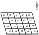
- FIG 1 is prior art depiction of a plenoptic micro-image matrix using a color filter array (CFA) used in a demosaicing process.
- CFA color filter array
- Demosaicing is a technique for processing digital images by reconstructing incomplete color sample output from an image sensor overlaid with a filter such as CFA used in Figure 1 .
- Color filter arrays are used in demosaicing processes are digital image processing techniques that use a color filter array to reconstruct a full color image from incomplete color samples. The color samples are often an output of one or more image sensors overlaid with a CFA.
- a color filter array is a mosaic of color filters in front of one or more image sensors. Commercially, the most commonly used CFA configuration is the Bayer filter.
- the prior art example of Figure 1 provides an example of such a filter.
- the alternating red (R) and green (G) filters for odd rows are further alternated in even rows with intervening rows that include interspersed green (G) and blue (B) filters.
- the Bayer pattern is a periodic pattern with a period of two different color pixels in each dimension (vertical and horizontal).
- a single period includes either a green pixel and a red pixel, or a blue pixel and a green pixel.
- a single period includes either a green pixel and a blue pixel, or a red pixel and a green pixel.
- the final result such as in this example, there are twice as many green filters as red or blue ones, catering to the human eye's higher sensitivity to green light.
- the color subsampling of a CFA by its nature results in aliasing, and therefore optical anti-aliasing filters are placed in the optical path between the image sensor and the lens to reduce the false color artifacts (chromatic aliases) introduced by interpolation.
- each pixel of the sensor is behind a color filter, the output is an array of pixel values, each indicating a raw intensity of one of the three filter colors.
- the Bayer filter is an example of a CFA that uses a multivariate interpolation on a uniform grid.
- an algorithm is needed to estimate for each pixel the color levels for all color components, rather than a single component.
- Conventional demosaicing algorithm reconstruct a full color image from such spatially under sampled color channels output from the CFA or other filters.
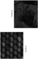
- Figure 2A is an exemplary embodiment illustrating micro-images captured by a plenoptic camera. Each pixel is illuminated by a sub-aperture of the exit pupil of the main lens. Due to the sampling through multiple lens, once the sub-aperture views are demultiplexed, the final images can have low resolution when compared to traditional imaging systems. These techniques will be discussed in more detail in conjunction with Figures 3 and 4 , this resolution can be greatly enhanced without requiring any additional sensors.
- the lighter shade represents green (G) while the darkest shade represent blue (B) and the medium gray shade represent the color red ( R).
- each pixel is illuminated by a sub-aperture of the exit pupil of the main lens.
- Figure 2B is an illustration of a demultiplex image as discussed.
- a scene is provided with views or images of one or more objects.
- the image was captured by a plenoptic camera.
- the overall contours an object is visible in Figure 2B , but there are not sufficient information provided in the image to allow for detailed object recognition.
- Even in instances where shade, intensity and colors are not totally missing, the complementary color information has to be interpolated from distant pixels which are problematic in most instances. This affects the resolution greatly.
- the demosaiced image is still missing information, but the image is demultiplexed in the appropriate manner. Without demosaicing, the raw data requires to be demultiplexed into views of the scene, without being demosaiced. Increasing the resolution requires using higher resolution sensors which use smaller "cells", leading to poorer performance in low light and higher noise. However, even if additional sensor cells of such quality are used, this technique will soon encounter limitations.
- the present technique as will be discussed in conjunction with Figures 3 and 4 , will provide a way to increase optical resolution so that any of the original sensors that have adequate to good performance can still be used with improved final resolution quality
- a medium that with the application of a voltage turns into a birefringence medium.
- Birefringence is the property of crystalline material that gives rise to production of two refracted rays when a ray hits them. This property is due to non isotropic distribution of atoms in the media and happens in crystalline media whose crystalline mesh structure is strongly non isotropic. Quartz and Calcite are natural material which exhibit birefringence. With those media, when a non polarized ray hits one of their surfaces which is at a special orientation, there are two rays that get created at refraction. One of these rays have one polarization characteristic and the other has a slightly different one.
- n i sin ⁇ i n r sin ⁇ r
- n i and n r are the respective (and different) refractive indices of the incident and refracted medium and ⁇ i and ⁇ r are the incident and refracted angles.
- Birefringent materials refract rays according to Snell's law but the effective index of refraction in the medial depends upon the input polarization state and the angle the refracted ray makes with respect to the crystal axis.
- the two type of rays can be defined as ordinary and extraordinary.
- the ray that obeys the Snell-Descartes law is called the ordinary ray and the medium has one ordinary index of refraction n o .
- the second ray that is created undergoes another refraction n e , it propagates in a direction within the material which has the extraordinary index n e and is polarized perpendicularly to the ordinary ray.
- two rays are created with different propagation directions.
- the angle ⁇ w is the angle between the crystal axis vector "a" and the refracted wave vector "k".
- the ray vector "s”, which is the vector pointing in the direction of energy propagation does not follow the wave vector "k", but makes small angles with respect to vector "k”.
- vectors "k” and “s” are the same. Therefore, for most optical designs, vector "k” must be taken into consideration.
- the wave vector k ⁇ points along the normal to the wavefront, while ⁇ points along the direction of energy propagation.
- Figure 3A illustrates a diagram for a sub-aperture to pixel mapping of both ordinary and extraordinary states.
- a plurality of rays (shown generally as 320) are passed through a medium shown by reference numerals 325.
- the exit pupil of the main lens shown by reference numeral 327 generally.
- This main lens exit is further divided into sub apertures V1 to V12, as shown by reference numerals 352 collectively.
- the medium 330 is electrically controllable.
- a birefringent material is used but a variety of similar mediums are available as can be appreciated by those skilled in the art.
- TN liquid crystal can be sandwiched between two glass plates having transparent Indium Tin Oxide (ITO) electrodes, in one embodiment.
- ITO Indium Tin Oxide
- the sub-apertures are imaged each onto one sole pixel per micro image following the green lines which depicts the ordinary rays.
- Figure 3A shows one micro-lens and one column of the pixels show how the ordinary ray map each sensor pixel to two sub-aperture pixels (one corresponding to the ordinary ray, one corresponding to the extraordinary ray).
- the blue rays shown in darker shade
- the extraordinary ray follows the blue path (dark gray in the Figure). It crosses the optical center of its microlens and then hits the birefringent cell 325.
- the cell is in its "extraordinary" state with an applied voltage and thus, this time, two rays are generated, the green which refracts as ordinary, and the blue one which refracts as the extraordinary ray.
- the ordinary ends up on one sub-aperture while the extraordinary ray maps into another sub-aperture. This means that if one begins from the exit pupil, in normal state, the ordinary ray of main sub-apertures (green v2-v12,v13-v23) will hit the sensor pixel and secondary sub-apertures are ignored dropped.
- Figures 3B and 3C each provide a more detail illustration of area 310 of Figure 3A . More specifically, Figure 3B shows the ordinary (green - light gray) rays in more detail, while Figure 3C shows the extraordinary (blue or dark gray) rays in more detail. In this way, sub-aperture to pixel mapping of ordinary (green) and extraordinary states (blue) of Figure 3A become more obvious by looking at the details provided in Figures 3B and 3C .
- pixels v1 to v11 are read, and pixels in between (e.g., v1/2 + v2/2 ... v11/2+v12/2) (rays not shown) fall in between sub-apertures.
- Adding resolution information to a plenoptic image requires two images to be taken sequentially. A first image is taken at t0 with the cell in the ordinary state.
- the pixels on the sensor do record the following states: P t 0 , v 2 , P t 0 , v 4 , P t 0 , v 6 , ... , P t 0 , v 12 , P t 0 , v 13 , P t 0 , v 15 , P t 0 , v 17 , ... , P t 0 , v 23
- a second image is taken at t1 with the cell in its extraordinary state.
- Two rays of equal intensities are generated if there is no polarizing phenomenon in the scene: P t 0 , v 1 / 2 + P t 0 , v 2 / 2 , P t 0 , v 3 / 2 + P t 0 , v 4 / 2
- the additional component used in this system is twisted nematic (TN) cell.
- the additional component used in this system is TN cell.
- the Liquid Crystal can have a big difference in value between the ordinary n 0 and extraordinary n e indices of refraction.
- a LC mixture named MLC-9200-100 as known to those skilled in the art for example can have n e -n 0 >0.2 which is a very big difference.
- this is needed in order to reduce the thickness of the cell. This thickness has to be adjusted to become compatible with a placement of the cell between the micro-lens array and the sensor, and therefore any size reduction may be helpful (even if by a few mm) in certain applications.
- Figure 4 is a flow chart depiction of the process explained above according to one embodiment.
- Figure 4 illustrates the steps for a method of generating multiple images of different color intensity and characteristics using a plenoptic camera having a main lens disposed ahead of an array of lenses having a plurality of apertures.
- a first set of images are captured using a first state of an electro optical polarization modulator.
- the modulator is disposed between said main lens and array of lenses with plurality of apertures.
- a second set of images are captured using a second state of an electro optical polarization modulator.
- the information about the second set of images is subtracted, such as for example with a configured processor, from information about the first set.
- a final set of images are generated after the subtraction such that said final set of images have enhanced resolution.
- a system for generating multiple images of different color intensity and characteristics can be used to conduct the method steps of Figure 4 and the arrangement of Figures 3A and 3B .
- a main lens (310) disposed in front of an array of lenses (352) associated with a plurality of apertures.
- An electrically controlled electro optical modulator (325) such as shown in Figure 3A can be disposed between the micro lens and the array of lenses shown. The electro optical modulator functions between the two states (330 and 340 in Figure 3A ) upon application of an electrical voltage.
- the first set of images are then captured using the first state of an electro optical polarization modulator and a second set of images are also captured using a second state of an electro optical polarization modulator as discussed in conjunction with Figure 4 .
- a processor can be incorporated into the system that is configured to subtract information about said second set of images from information about the first set of captured images to generate (440 in Figure 4 ) a final set of images with enhanced color intensity and characteristics. In this manner rich color information can be obtained, even in a very complicated situation, where a plenoptic camera delivers very sparse color information.
Landscapes
- Engineering & Computer Science (AREA)
- Multimedia (AREA)
- Signal Processing (AREA)
- Theoretical Computer Science (AREA)
- Computing Systems (AREA)
- Physics & Mathematics (AREA)
- General Physics & Mathematics (AREA)
- Spectroscopy & Molecular Physics (AREA)
- Color Television Image Signal Generators (AREA)
- Studio Devices (AREA)
- Transforming Light Signals Into Electric Signals (AREA)
- Focusing (AREA)
Applications Claiming Priority (3)
| Application Number | Priority Date | Filing Date | Title |
|---|---|---|---|
| EP16305821.7A EP3264741A1 (de) | 2016-06-30 | 2016-06-30 | Ansichtsmischung durch plenoptische unterblendenöffnungen mit verbesserter auflösung |
| EP17732467.0A EP3479561B1 (de) | 2016-06-30 | 2017-06-27 | Plenoptische kamera mit höherer auflösung unter verwendung einer kontrollierbaren doppelbrechenden schicht |
| PCT/EP2017/065914 WO2018002089A1 (en) | 2016-06-30 | 2017-06-27 | Plenoptic sub aperture view shuffling with improved resolution |
Related Parent Applications (2)
| Application Number | Title | Priority Date | Filing Date |
|---|---|---|---|
| EP17732467.0A Division EP3479561B1 (de) | 2016-06-30 | 2017-06-27 | Plenoptische kamera mit höherer auflösung unter verwendung einer kontrollierbaren doppelbrechenden schicht |
| EP17732467.0A Division-Into EP3479561B1 (de) | 2016-06-30 | 2017-06-27 | Plenoptische kamera mit höherer auflösung unter verwendung einer kontrollierbaren doppelbrechenden schicht |
Publications (2)
| Publication Number | Publication Date |
|---|---|
| EP4243435A2 true EP4243435A2 (de) | 2023-09-13 |
| EP4243435A3 EP4243435A3 (de) | 2023-10-25 |
Family
ID=56411558
Family Applications (3)
| Application Number | Title | Priority Date | Filing Date |
|---|---|---|---|
| EP16305821.7A Withdrawn EP3264741A1 (de) | 2016-06-30 | 2016-06-30 | Ansichtsmischung durch plenoptische unterblendenöffnungen mit verbesserter auflösung |
| EP17732467.0A Active EP3479561B1 (de) | 2016-06-30 | 2017-06-27 | Plenoptische kamera mit höherer auflösung unter verwendung einer kontrollierbaren doppelbrechenden schicht |
| EP23184051.3A Withdrawn EP4243435A3 (de) | 2016-06-30 | 2017-06-27 | Plenoptische kamera mit höherer auflösung unter verwendung einer kontrollierbaren doppelbrechenden schicht |
Family Applications Before (2)
| Application Number | Title | Priority Date | Filing Date |
|---|---|---|---|
| EP16305821.7A Withdrawn EP3264741A1 (de) | 2016-06-30 | 2016-06-30 | Ansichtsmischung durch plenoptische unterblendenöffnungen mit verbesserter auflösung |
| EP17732467.0A Active EP3479561B1 (de) | 2016-06-30 | 2017-06-27 | Plenoptische kamera mit höherer auflösung unter verwendung einer kontrollierbaren doppelbrechenden schicht |
Country Status (10)
| Country | Link |
|---|---|
| US (2) | US10834313B2 (de) |
| EP (3) | EP3264741A1 (de) |
| JP (2) | JP6998898B2 (de) |
| KR (2) | KR102314719B1 (de) |
| CN (2) | CN113766107B (de) |
| BR (1) | BR112018077493A2 (de) |
| CA (1) | CA3029463A1 (de) |
| MX (1) | MX2018016308A (de) |
| RU (1) | RU2019102372A (de) |
| WO (1) | WO2018002089A1 (de) |
Families Citing this family (3)
| Publication number | Priority date | Publication date | Assignee | Title |
|---|---|---|---|---|
| CN108776954B (zh) * | 2018-06-26 | 2020-04-28 | 北京字节跳动网络技术有限公司 | 用于生成图像的方法和装置 |
| CN108921801B (zh) * | 2018-06-26 | 2020-01-07 | 北京字节跳动网络技术有限公司 | 用于生成图像的方法和装置 |
| DE102019133642A1 (de) * | 2018-12-12 | 2020-06-18 | Magna Closures Inc. | Digitales bildgebungssystem einschliesslich optischer plenoptik-vorrichtung und bilddaten-verarbeitungsverfahren zur erfassung von fahrzeughindernissen und gesten |
Family Cites Families (40)
| Publication number | Priority date | Publication date | Assignee | Title |
|---|---|---|---|---|
| US4394069A (en) * | 1979-06-05 | 1983-07-19 | Beckman Instruments, Inc. | Liquid crystal tuned birefringent filter |
| JP3380913B2 (ja) * | 1992-06-11 | 2003-02-24 | ソニー株式会社 | 固体撮像装置 |
| JPH08250692A (ja) * | 1995-03-10 | 1996-09-27 | Sharp Corp | 光学装置 |
| JPH09130818A (ja) * | 1995-08-29 | 1997-05-16 | Casio Comput Co Ltd | 撮像装置と撮像方法 |
| CN100417230C (zh) * | 2000-06-16 | 2008-09-03 | 夏普公司 | 投影型图象显示装置 |
| JP2004151139A (ja) * | 2002-10-28 | 2004-05-27 | Sharp Corp | 光学シフト素子および投影型画像表示装置 |
| KR100657695B1 (ko) * | 2004-12-15 | 2006-12-14 | 주식회사 대우일렉트로닉스 | 홀로그래픽 롬 디스크의 기준광 서보 제어방법 및 그 장치 |
| US7620309B2 (en) * | 2006-04-04 | 2009-11-17 | Adobe Systems, Incorporated | Plenoptic camera |
| JP2008167154A (ja) | 2006-12-28 | 2008-07-17 | Sony Corp | 撮像装置 |
| CN103839955B (zh) * | 2007-04-18 | 2016-05-25 | 因维萨热技术公司 | 用于光电装置的材料、系统和方法 |
| US7962033B2 (en) * | 2008-01-23 | 2011-06-14 | Adobe Systems Incorporated | Methods and apparatus for full-resolution light-field capture and rendering |
| CN101884215A (zh) | 2008-10-02 | 2010-11-10 | 松下电器产业株式会社 | 像素错开型摄像装置 |
| JP4529010B1 (ja) | 2009-03-30 | 2010-08-25 | シャープ株式会社 | 撮像装置 |
| JP5453958B2 (ja) * | 2009-07-01 | 2014-03-26 | ソニー株式会社 | 撮像装置 |
| US9310302B2 (en) * | 2009-10-12 | 2016-04-12 | Ventana Medical Systems, Inc. | Multi-modality contrast and brightfield context rendering for enhanced pathology determination and multi-analyte detection in tissue |
| US8502909B2 (en) * | 2009-10-19 | 2013-08-06 | Pixar | Super light-field lens |
| JP5568945B2 (ja) * | 2009-10-20 | 2014-08-13 | 株式会社リコー | 画像形成装置 |
| WO2011063347A2 (en) | 2009-11-20 | 2011-05-26 | Pelican Imaging Corporation | Capturing and processing of images using monolithic camera array with heterogeneous imagers |
| KR101608970B1 (ko) | 2009-11-27 | 2016-04-05 | 삼성전자주식회사 | 광 필드 데이터를 이용한 영상 처리 장치 및 방법 |
| US8504328B2 (en) | 2010-05-21 | 2013-08-06 | Eastman Kodak Company | Designing lenses using stress birefringence performance criterion |
| JP2012042859A (ja) | 2010-08-23 | 2012-03-01 | Olympus Corp | 撮像装置 |
| US8542288B2 (en) | 2010-11-03 | 2013-09-24 | Sony Corporation | Camera system and imaging method using multiple lens and aperture units |
| JP5764747B2 (ja) * | 2011-09-02 | 2015-08-19 | パナソニックIpマネジメント株式会社 | 偏光撮像素子および内視鏡 |
| JP5913934B2 (ja) | 2011-11-30 | 2016-05-11 | キヤノン株式会社 | 画像処理装置、画像処理方法およびプログラム、および画像処理装置を有する撮像装置 |
| JP6004280B2 (ja) | 2012-02-08 | 2016-10-05 | パナソニックIpマネジメント株式会社 | ライトフィールド撮像装置および撮像素子 |
| KR20140061234A (ko) * | 2012-11-13 | 2014-05-21 | 삼성전자주식회사 | 이미지 생성 장치 및 이미지 생성 방법 |
| US9137524B2 (en) * | 2012-11-27 | 2015-09-15 | Qualcomm Incorporated | System and method for generating 3-D plenoptic video images |
| US20140354777A1 (en) * | 2013-05-29 | 2014-12-04 | Electronics And Telecommunications Research Institute | Apparatus and method for obtaining spatial information using active array lens |
| JP5805153B2 (ja) * | 2013-08-08 | 2015-11-04 | キヤノン株式会社 | レンズ装置及びその制御方法 |
| AU2014310703B2 (en) * | 2013-08-19 | 2018-09-27 | Basf Se | Optical detector |
| CN108638690B (zh) * | 2013-09-04 | 2020-04-21 | 卢门科有限责任公司 | 一种制造防伪器件的方法 |
| CN103673961B (zh) * | 2013-12-12 | 2016-05-11 | 广州广电运通金融电子股份有限公司 | 一种薄片介质厚度检测装置及方法 |
| JP6183207B2 (ja) * | 2013-12-26 | 2017-08-23 | アイシン・エィ・ダブリュ株式会社 | 自動変速機の制御装置 |
| US9525819B2 (en) | 2014-03-07 | 2016-12-20 | Ricoh Company, Ltd. | Enhancing spatial resolution of images from light field imaging systems using sub-pixel disparity |
| JP5881777B2 (ja) * | 2014-06-24 | 2016-03-09 | オリンパス株式会社 | 顕微鏡 |
| US10746600B2 (en) * | 2015-01-09 | 2020-08-18 | California Institute Of Technology | Dual wavelength context imaging Raman and fluorescence spectrometer |
| US10048130B2 (en) * | 2015-01-09 | 2018-08-14 | California Institute Of Technology | Context imaging raman spectrometer |
| US10531071B2 (en) * | 2015-01-21 | 2020-01-07 | Nextvr Inc. | Methods and apparatus for environmental measurements and/or stereoscopic image capture |
| US10085005B2 (en) * | 2015-04-15 | 2018-09-25 | Lytro, Inc. | Capturing light-field volume image and video data using tiled light-field cameras |
| US10901193B2 (en) * | 2016-02-26 | 2021-01-26 | University Of Southern California | Optimized volumetric imaging with selective volume illumination and light field detection |
-
2016
- 2016-06-30 EP EP16305821.7A patent/EP3264741A1/de not_active Withdrawn
-
2017
- 2017-06-27 KR KR1020197002535A patent/KR102314719B1/ko active Active
- 2017-06-27 JP JP2018567102A patent/JP6998898B2/ja active Active
- 2017-06-27 WO PCT/EP2017/065914 patent/WO2018002089A1/en not_active Ceased
- 2017-06-27 CN CN202111023183.5A patent/CN113766107B/zh active Active
- 2017-06-27 CN CN201780039763.9A patent/CN109417590B/zh active Active
- 2017-06-27 RU RU2019102372A patent/RU2019102372A/ru not_active Application Discontinuation
- 2017-06-27 KR KR1020217032991A patent/KR102461778B1/ko active Active
- 2017-06-27 EP EP17732467.0A patent/EP3479561B1/de active Active
- 2017-06-27 BR BR112018077493-6A patent/BR112018077493A2/pt not_active IP Right Cessation
- 2017-06-27 US US16/314,581 patent/US10834313B2/en active Active
- 2017-06-27 MX MX2018016308A patent/MX2018016308A/es unknown
- 2017-06-27 CA CA3029463A patent/CA3029463A1/en not_active Abandoned
- 2017-06-27 EP EP23184051.3A patent/EP4243435A3/de not_active Withdrawn
-
2020
- 2020-10-05 US US17/062,806 patent/US11438503B2/en active Active
-
2021
- 2021-12-21 JP JP2021207302A patent/JP7528051B2/ja active Active
Also Published As
| Publication number | Publication date |
|---|---|
| RU2019102372A (ru) | 2020-07-30 |
| KR102461778B1 (ko) | 2022-11-01 |
| US11438503B2 (en) | 2022-09-06 |
| WO2018002089A1 (en) | 2018-01-04 |
| US20210021758A1 (en) | 2021-01-21 |
| JP7528051B2 (ja) | 2024-08-05 |
| JP6998898B2 (ja) | 2022-01-18 |
| JP2022046601A (ja) | 2022-03-23 |
| CN109417590B (zh) | 2021-09-10 |
| EP3479561A1 (de) | 2019-05-08 |
| US20190158736A1 (en) | 2019-05-23 |
| CA3029463A1 (en) | 2018-01-04 |
| EP3479561B1 (de) | 2023-09-06 |
| RU2019102372A3 (de) | 2020-10-22 |
| EP3264741A1 (de) | 2018-01-03 |
| KR20210127809A (ko) | 2021-10-22 |
| EP4243435A3 (de) | 2023-10-25 |
| KR20190022770A (ko) | 2019-03-06 |
| MX2018016308A (es) | 2019-10-07 |
| US10834313B2 (en) | 2020-11-10 |
| CN113766107A (zh) | 2021-12-07 |
| BR112018077493A2 (pt) | 2019-04-09 |
| JP2019521599A (ja) | 2019-07-25 |
| KR102314719B1 (ko) | 2021-10-20 |
| CN109417590A (zh) | 2019-03-01 |
| CN113766107B (zh) | 2024-06-04 |
Similar Documents
| Publication | Publication Date | Title |
|---|---|---|
| Venkataraman et al. | Picam: An ultra-thin high performance monolithic camera array | |
| US8436909B2 (en) | Compound camera sensor and related method of processing digital images | |
| CN101437168B (zh) | 图像拾取装置 | |
| JP5224124B2 (ja) | 撮像装置 | |
| JP7528051B2 (ja) | 改善された解像度を用いたプレノプティック・サブアパーチャ・ビュー・シャッフリング | |
| CN101455071B (zh) | 改进的全光照相机 | |
| JP5995084B2 (ja) | 3次元撮像装置、撮像素子、光透過部、および画像処理装置 | |
| US10931936B2 (en) | Plenoptic sub aperture view shuffling for a richer color sampling | |
| Georgiev et al. | Using focused plenoptic cameras for rich image capture | |
| US20250220315A1 (en) | High-dynamic range imaging using partial polarisation mask | |
| Palum et al. | Optical antialiasing filters | |
| Yang | Advancing Mobile Photography With Under-Display Cameras and Sensor Design |
Legal Events
| Date | Code | Title | Description |
|---|---|---|---|
| PUAI | Public reference made under article 153(3) epc to a published international application that has entered the european phase |
Free format text: ORIGINAL CODE: 0009012 |
|
| STAA | Information on the status of an ep patent application or granted ep patent |
Free format text: STATUS: THE APPLICATION HAS BEEN PUBLISHED |
|
| AC | Divisional application: reference to earlier application |
Ref document number: 3479561 Country of ref document: EP Kind code of ref document: P |
|
| AK | Designated contracting states |
Kind code of ref document: A2 Designated state(s): AL AT BE BG CH CY CZ DE DK EE ES FI FR GB GR HR HU IE IS IT LI LT LU LV MC MK MT NL NO PL PT RO RS SE SI SK SM TR |
|
| REG | Reference to a national code |
Ref country code: DE Ref legal event code: R079 Free format text: PREVIOUS MAIN CLASS: H04N0023951000 Ipc: H04N0013232000 |
|
| PUAL | Search report despatched |
Free format text: ORIGINAL CODE: 0009013 |
|
| AK | Designated contracting states |
Kind code of ref document: A3 Designated state(s): AL AT BE BG CH CY CZ DE DK EE ES FI FR GB GR HR HU IE IS IT LI LT LU LV MC MK MT NL NO PL PT RO RS SE SI SK SM TR |
|
| RIC1 | Information provided on ipc code assigned before grant |
Ipc: H04N 23/951 20230101ALI20230921BHEP Ipc: H04N 23/12 20230101ALI20230921BHEP Ipc: H04N 13/296 20180101ALI20230921BHEP Ipc: H04N 13/232 20180101AFI20230921BHEP |
|
| STAA | Information on the status of an ep patent application or granted ep patent |
Free format text: STATUS: THE APPLICATION IS DEEMED TO BE WITHDRAWN |
|
| 18D | Application deemed to be withdrawn |
Effective date: 20240426 |