EP4242138A1 - Système de stockage avec appareil de levage à plaque guidée pour chargement-déchargement de charge utile sur un bâti de stockage - Google Patents
Système de stockage avec appareil de levage à plaque guidée pour chargement-déchargement de charge utile sur un bâti de stockage Download PDFInfo
- Publication number
- EP4242138A1 EP4242138A1 EP23150447.3A EP23150447A EP4242138A1 EP 4242138 A1 EP4242138 A1 EP 4242138A1 EP 23150447 A EP23150447 A EP 23150447A EP 4242138 A1 EP4242138 A1 EP 4242138A1
- Authority
- EP
- European Patent Office
- Prior art keywords
- lifting
- cam
- guide
- storage
- follower
- Prior art date
- Legal status (The legal status is an assumption and is not a legal conclusion. Google has not performed a legal analysis and makes no representation as to the accuracy of the status listed.)
- Pending
Links
- 230000007246 mechanism Effects 0.000 claims abstract description 102
- 230000033001 locomotion Effects 0.000 claims abstract description 36
- 230000014759 maintenance of location Effects 0.000 claims abstract description 22
- 239000000725 suspension Substances 0.000 claims description 10
- 239000007787 solid Substances 0.000 claims description 7
- 230000000694 effects Effects 0.000 claims description 3
- 238000013459 approach Methods 0.000 abstract description 2
- 238000000034 method Methods 0.000 description 6
- 230000007423 decrease Effects 0.000 description 4
- 230000006870 function Effects 0.000 description 4
- 230000004048 modification Effects 0.000 description 4
- 238000012986 modification Methods 0.000 description 4
- 230000009471 action Effects 0.000 description 3
- 239000002131 composite material Substances 0.000 description 3
- 238000013461 design Methods 0.000 description 3
- 238000011161 development Methods 0.000 description 2
- 238000010586 diagram Methods 0.000 description 2
- 230000008569 process Effects 0.000 description 2
- 230000008439 repair process Effects 0.000 description 2
- 230000004913 activation Effects 0.000 description 1
- 230000006978 adaptation Effects 0.000 description 1
- 230000003466 anti-cipated effect Effects 0.000 description 1
- 230000005540 biological transmission Effects 0.000 description 1
- 230000008859 change Effects 0.000 description 1
- 230000009193 crawling Effects 0.000 description 1
- 230000009849 deactivation Effects 0.000 description 1
- 230000006872 improvement Effects 0.000 description 1
- 239000000463 material Substances 0.000 description 1
- 230000009467 reduction Effects 0.000 description 1
- 125000006850 spacer group Chemical group 0.000 description 1
- 230000001052 transient effect Effects 0.000 description 1
- 230000001960 triggered effect Effects 0.000 description 1
Images


Classifications
-
- B—PERFORMING OPERATIONS; TRANSPORTING
- B65—CONVEYING; PACKING; STORING; HANDLING THIN OR FILAMENTARY MATERIAL
- B65G—TRANSPORT OR STORAGE DEVICES, e.g. CONVEYORS FOR LOADING OR TIPPING, SHOP CONVEYOR SYSTEMS OR PNEUMATIC TUBE CONVEYORS
- B65G1/00—Storing articles, individually or in orderly arrangement, in warehouses or magazines
- B65G1/02—Storage devices
- B65G1/04—Storage devices mechanical
- B65G1/0492—Storage devices mechanical with cars adapted to travel in storage aisles
-
- B—PERFORMING OPERATIONS; TRANSPORTING
- B65—CONVEYING; PACKING; STORING; HANDLING THIN OR FILAMENTARY MATERIAL
- B65G—TRANSPORT OR STORAGE DEVICES, e.g. CONVEYORS FOR LOADING OR TIPPING, SHOP CONVEYOR SYSTEMS OR PNEUMATIC TUBE CONVEYORS
- B65G65/00—Loading or unloading
- B65G65/02—Loading or unloading machines comprising essentially a conveyor for moving the loads associated with a device for picking-up the loads
-
- B—PERFORMING OPERATIONS; TRANSPORTING
- B65—CONVEYING; PACKING; STORING; HANDLING THIN OR FILAMENTARY MATERIAL
- B65G—TRANSPORT OR STORAGE DEVICES, e.g. CONVEYORS FOR LOADING OR TIPPING, SHOP CONVEYOR SYSTEMS OR PNEUMATIC TUBE CONVEYORS
- B65G1/00—Storing articles, individually or in orderly arrangement, in warehouses or magazines
- B65G1/02—Storage devices
- B65G1/04—Storage devices mechanical
- B65G1/0407—Storage devices mechanical using stacker cranes
- B65G1/0428—Transfer means for the stacker crane between the alleys
-
- B—PERFORMING OPERATIONS; TRANSPORTING
- B65—CONVEYING; PACKING; STORING; HANDLING THIN OR FILAMENTARY MATERIAL
- B65G—TRANSPORT OR STORAGE DEVICES, e.g. CONVEYORS FOR LOADING OR TIPPING, SHOP CONVEYOR SYSTEMS OR PNEUMATIC TUBE CONVEYORS
- B65G1/00—Storing articles, individually or in orderly arrangement, in warehouses or magazines
- B65G1/02—Storage devices
- B65G1/04—Storage devices mechanical
- B65G1/0407—Storage devices mechanical using stacker cranes
- B65G1/0435—Storage devices mechanical using stacker cranes with pulling or pushing means on either stacking crane or stacking area
-
- B—PERFORMING OPERATIONS; TRANSPORTING
- B65—CONVEYING; PACKING; STORING; HANDLING THIN OR FILAMENTARY MATERIAL
- B65G—TRANSPORT OR STORAGE DEVICES, e.g. CONVEYORS FOR LOADING OR TIPPING, SHOP CONVEYOR SYSTEMS OR PNEUMATIC TUBE CONVEYORS
- B65G1/00—Storing articles, individually or in orderly arrangement, in warehouses or magazines
- B65G1/02—Storage devices
- B65G1/04—Storage devices mechanical
- B65G1/0485—Check-in, check-out devices
-
- B—PERFORMING OPERATIONS; TRANSPORTING
- B65—CONVEYING; PACKING; STORING; HANDLING THIN OR FILAMENTARY MATERIAL
- B65G—TRANSPORT OR STORAGE DEVICES, e.g. CONVEYORS FOR LOADING OR TIPPING, SHOP CONVEYOR SYSTEMS OR PNEUMATIC TUBE CONVEYORS
- B65G1/00—Storing articles, individually or in orderly arrangement, in warehouses or magazines
- B65G1/02—Storage devices
- B65G1/04—Storage devices mechanical
- B65G1/06—Storage devices mechanical with means for presenting articles for removal at predetermined position or level
-
- B—PERFORMING OPERATIONS; TRANSPORTING
- B65—CONVEYING; PACKING; STORING; HANDLING THIN OR FILAMENTARY MATERIAL
- B65G—TRANSPORT OR STORAGE DEVICES, e.g. CONVEYORS FOR LOADING OR TIPPING, SHOP CONVEYOR SYSTEMS OR PNEUMATIC TUBE CONVEYORS
- B65G15/00—Conveyors having endless load-conveying surfaces, i.e. belts and like continuous members, to which tractive effort is transmitted by means other than endless driving elements of similar configuration
- B65G15/28—Conveyors with a load-conveying surface formed by a single flat belt, not otherwise provided for
-
- B—PERFORMING OPERATIONS; TRANSPORTING
- B66—HOISTING; LIFTING; HAULING
- B66F—HOISTING, LIFTING, HAULING OR PUSHING, NOT OTHERWISE PROVIDED FOR, e.g. DEVICES WHICH APPLY A LIFTING OR PUSHING FORCE DIRECTLY TO THE SURFACE OF A LOAD
- B66F9/00—Devices for lifting or lowering bulky or heavy goods for loading or unloading purposes
- B66F9/06—Devices for lifting or lowering bulky or heavy goods for loading or unloading purposes movable, with their loads, on wheels or the like, e.g. fork-lift trucks
- B66F9/063—Automatically guided
Definitions
- the disclosure herein generally relates to the field of automated storage systems, and, more particularly, to a storage system with guided plate based lifting apparatus for payload loading or unloading on a storage rack.
- racks in the warehouses are being loaded or unloaded by using manual or semi-automated forklifts.
- There exist few other techniques in the industries which control an inventory storage and retrieval of goods or payloads such as single deep, double deep and dense storage systems, warehouse shuttle system and the like. However, they are inefficient for payload movement and have a considerable downtime when they need repair.
- Autonomous, non-rigid, scalable storage and retrieval systems is an open area for development, which demands time and space efficient storage and retrieval of goods.
- Embodiments of the present disclosure present technological improvements as solutions to one or more of the above-mentioned technical problems recognized by the inventors in conventional systems.
- a storage system is provided.
- the storage system comprising: (a) a plurality of lifting apparatuses, wherein each of the plurality of lifting apparatuses when at a rest position, locks on a landing platform of an Automated Vehicle (AV), wherein locking is guided by a plurality of male connectors and a plurality of female connectors enabling each of the plurality of lifting apparatuses to self-align a plurality of charging ports on the plurality of lifting apparatuses with a plurality of charging pads provided on the landing platform for charging of each of the plurality of lifting apparatuses when in the rest position, (b) a plurality of guide plates mounted on each corner of each of a plurality of storage racks, wherein each of the plurality of lifting apparatuses is aligned with the plurality of guide plates by the AV via a to and fro movement in an aisle between two storage racks.
- AV Automated Vehicle
- the guide plates comprises: a plurality of entry cuts provided in the plurality of guide plates for the to and fro movement of the AV mounted with the plurality of lifting apparatuses in the rest position; a plurality of entry guides for each of the plurality of lifting apparatuses for vertical movement along each of the plurality of storage racks guided by the plurality of guide plates; and a plurality of ramps at bottom of the storage racks to smoothen lifting of each of the plurality of lifting apparatuses onto the plurality of guide plates.
- Each of the plurality of lifting apparatuses comprising: a base plate at a bottom end holding the charging port on one side and the male connector on other side; a plurality of pipes, with one end of each of the plurality of pipes connected to a plurality of supporting brackets at each corner of the base plate using a plurality of split clamps, and other end of the plurality of pipes is connected to each corner of a top plate using the plurality of split clamps screwed to the top plate; a top cover mounted over the top plate providing an enclosure for electrical and control elements and a battery for powering up and functioning of each of the plurality of lifting apparatuses; a plurality of X frames mounted on the plurality of pipes on one set of opposites sides of the base plate using a plurality of C clamps, each of the plurality of X frame consists of a wheel retention mechanism comprising a timer belt pulley mechanism with a CAM-follower mechanism mounted on each of the plurality of X frame; and a set of drive wheels and a set of follow
- Each of the set of drive wheels is powered by a drive motor which is coupled by a drive wheel coupler mounted on a wheel mount bracket, and wherein the set of drive wheels propel the lifting apparatus upwards through the plurality of guide plates while the set of follower wheels follow the set of drive wheels.
- the wheel retention mechanism, the timer belt pulley mechanism with the CAM-follower mechanism of each of the X frame comprises: (a) a LM rail and a LM guide, wherein the LM rail is screwed into a slot of the X frame and the LM guide slides over the LM rail, wherein one end of the LM guide is fixed to a flat step of a CAM follower link of a CAM follower of the CAM-follower mechanism and has a solid step at bottom to slide inside a hole provided at one end of the LM rail, wherein the flat step of the CAM follower link is held using a flanged screw, the flanged screw is configured to enable to and fro movement of the CAM-follower mechanism via the slot provided on the flat step of the CAM follower link, wherein the flanged screw is further configured to retain a the CAM follower link coming out from the slot, and wherein the flat step end of the CAM follower link further provides anti-rotational movement for the wheel retention
- the CAM with the timer belt pulley mechanism is mounted onto a plurality of bearings and is further coupled to the center of the X frame, and wherein a X frame motor mounted onto the X frame activates or deactivates the CAM-follower mechanism to control spacing between the plurality of guide plates and set of drive wheels and the set of follower wheels.
- the storage system further providing a loading unloading mechanism for loading or unloading of a payload via the lifting apparatus, wherein the loading unloading mechanism comprises: a conveyor belt mechanism for a conveyor belt comprising a first end with a powered roller rotated by a conveyor motor mounted to the conveyor belt mechanism and a second end with a free roller, wherein the conveyor belt is supported by an intermediate roller and the free roller to take and guide the payload.
- a sliding mechanism of the conveyor belt mechanism comprises a sliding mechanism with plurality of guide rods sliding into a plurality of bearing bushes mounted onto the base plate.
- the sliding mechanism further comprising a rack gear mounted to the sliding mechanism from a bottom side of the conveyor belt mechanism, which is coupled and rotated by a pinion gear and a sliding motor arrangement mounted to the base plate.
- the pinion gear associated with the sliding motor is directly coupled to the rack gear, wherein rotary motion of the sliding motor converts the sliding motion of the rack gear which slides the sliding mechanism, and wherein the sliding mechanism of the conveyor belt mechanism guides loading or /unloading of the payload inside or/outside a storage space of interest among a plurality of storage spaces arranged vertically in a the storage rack based on the direction of revolution of the conveyor motor.
- Embodiments herein provide a storage system with guided plate based lifting apparatus for payload loading-unloading on storage rack.
- the system deploys an Automated Vehicle such as An Automated Guided Vehicle/Autonomous Mobile Robot (AGV/AMR) mounted with multiple lifting apparatuses in between two adjacent storage racks.
- the racks are modified with guide plates having entry cutouts for horizontal movements and entry guides for vertical movement of lifting apparatus.
- Ramp provided in the guide plates at the bottom of racks ensures there is enough clearance for lifting apparatus to go inside an aisle and have smooth vertical lifting.
- Wheel retention mechanism guides the vertical lifting maintaining required clearance.
- a conveyor belt mechanism mounted to base plate of lifting apparatus consists of geared rotary motor for conveyor belt that has a forward and backward movement, enabling the lifting apparatus to load or unload the payload inside or outside the racks.
- FIG. 1A through FIG. 7B where similar reference characters denote corresponding features consistently throughout the figures, there are shown preferred embodiments and these embodiments are described in the context of the following exemplary system and/or method.
- Reference numerals of one or more components of the autonomous surface crawling robot as depicted in the FIGS. 1A through 7B are provided in Table 1 below for ease of description: Table 1 S1.
- FIG. 1 No Component with alternative name Numeral reference 1 Storage System 100 2 Plurality of Lifting apparatuses (lifting apparatuses) 200A-B 3 Plurality of Male connectors (male connectors) 202A-B 4 Plurality of Charging ports (charging ports) 204A-B 5 Base plate 206 6 Plurality of Pipes (pipes) 208A-D 7 Plurality of Supporting brackets(supporting brackets) 210A-D 8 Plurality of Split Clamps (split claims) 212A-D 9 Top plate 214 10 Top cover 216 11 Plurality of X frames (X frames) 218A-B 12 X frame motor 218A-1 13 Plurality of C clamps (C clamps) 220A-D 14 Wheel retention mechanism 222A-1 15 Timer belt pully mechanism 222A-2 16 CAM-follower mechanism 222A-3 17 Set of Drive wheels 224A-D 18 Set of Follower wheels 226A-D 19 Conveyor belt 228 20 Conveyor motor
- FIG. 1A illustrates a partial isometric view (or a perspective view) of a storage system 100 comprising a plurality of lifting apparatuses (200A-B), mounted on an Automated Vehicle (AV) (300), such as an Automated Guided Vehicle/Autonomous Mobile Robot (AGV/AMR) (300) that enters into an aisle in storage racks (500A-N), according to some embodiments of the present disclosure.
- FIG. 1B is a first partial isometric view of the storage system (100) depicting a lifting apparatus (200A) at rest position, according to some embodiments of the present disclosure.
- FIG. 1C is a second partial isometric view of the storage system (100) depicting the plurality of lifting apparatuses (200A-B) at rest position inside the aisle, according to some embodiments of the present disclosure.
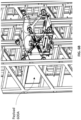
- FIG. 1D illustrates a partial top view of the storage system (100), according to some embodiments of the present disclosure.
- FIG. 1E illustrates an isometric view of electrical and mechanical connection between the AGV/AMR (300) and the lifting apparatus (200A-B), according to some embodiments of the present disclosure.
- FIGS. 1A through 1E are collectively referred as FIG. 1 .
- the storage system 100 comprises the plurality of lifting apparatuses (200A-B).
- Each of the plurality of lifting apparatuses (200A-B) at the rest position locks on a landing platform (304) of the AGV/AMR (300).
- the AGV/AMR (300) is guided by a guide path (302) into the aisle (narrow passageway between two rows of the storage racks).
- locking of the plurality of lifting apparatuses (200A-B) is guided by a plurality of male connectors (202A-B) and a plurality of female connectors (306A-B).
- each of the plurality of lifting apparatuses (200A-B) to self-align a plurality of charging ports (204A-B) on the plurality of lifting apparatuses (200A-B) with a plurality of charging pads (308A-B) provided on the landing platform (304) for charging of each of the plurality of lifting apparatuses (200A-B).
- the charging is triggered automatically when the lifting apparatus is at rest position.
- a plurality of guide plates (400A-N) is mounted on each corner of each of the plurality of storage racks (500A-N).
- the storage system (100) disclosed herein has modified storage racks attached with guide plates.
- Each of the plurality of lifting apparatuses (200A-B) is aligned with the guide plates (400A-N) by the AGV/AMR (300) via a to and fro movement in the aisle between two storage racks (500A-B). Once aligned with the guide plates of the corresponding storage racks, the lifting apparatuses (200A-B) are ready to move upward for loading or unloading of payloads (600A-B).
- the design of the plurality of male connectors (202A-B) and the plurality of female connectors (306A-B) is done in such a way that, as soon as the lifting apparatus (200A) lands onto the landing platform (304) the male connector (202A) enters the female connector (306A) within the clearance band given in between roller wheels of the lifting apparatus (200A) and the plurality of guide plates (400A-B).
- the roller wheels include a set of drive wheels (224A-D) and a set of follower wheels (226A-D) as explained later in conjunction with FIG. 3 , and FIGS. 4A and 4B .
- the lifting apparatus (200A) With the entry curve feature between the male connector (202A) and the female connector (306A), the lifting apparatus (200A) is able to locate itself. Additionally, at second end rubber pads are also provided with entry chamfer which come and re-locate within the fixed rubber pads. Further, once the lifting apparatus (200A) gets aligned then the charging ports connect to each other. Fixed mounted charging ports are made wide enough to accommodate any lateral errors during the lifting apparatus alignment
- a plurality of entry cuts (402AN) are provided in the guide plates (400A-N) for the to and fro movement of the AGV/AMR while entering the aisle, while mounted with the plurality of lifting apparatuses (200A-B) in the rest position.
- FIG. 1B a plurality of entry cuts (402AN) are provided in the guide plates (400A-N) for the to and fro movement of the AGV/AMR while entering the aisle, while mounted with the plurality of lifting apparatuses (200A-B) in the rest position.
- FIGS. 2A , 2B and 2C depict wheel movement of the lifting apparatus during vertical movement between the storage racks in the storage system, according to some embodiments of the present disclosure.
- FIG. 2A depicts a front view of the storage system (100), wherein roller wheels (set of drive wheels (224A-D) and a set of follower wheels (226A-D) of the lifting apparatus (200A) are in contracted position, that creates a clearance gap between roller wheels and the guide plates (400A-B).
- FIG. 2A depicts a front view of the storage system (100), wherein roller wheels (set of drive wheels (224A-D) and a set of follower wheels (226A-D) of the lifting apparatus (200A) are in contracted position, that creates a clearance gap between roller wheels and the guide plates (400A-B).
- FIG. 2B depicts wheel area close up of the storage system (100) to understand clearance between a roller wheel (such as 224A) and a guide plate (400A) (Zone A,B,C,D).
- FIG. 2C depicts wheel area close-up of the storage system (100) with top view to understand (i) zero clearance between the roller wheel and the guide plate from side q when the roller wheels are in extended position, (ii) full engagement between the roller wheel and the guide plate, and (iii) side clearance between the roller wheel and the guide plate.
- ramps (406A-N) at bottom of the storage racks (500A-N) are provided to smoothen lifting of each of the plurality of lifting apparatuses (200A-B) onto the guide plates (400A-N).
- the ramps (406A-N) are at a height equal to the AGV/AMR (300) with lifting apparatus's height. This ensures there is enough clearance for the lifting apparatus (200A) to go inside the aisle and to smoothen vertical lifting of lifting apparatus as well as horizontal movement of an AGV/AMR at ground level.
- Each of the plurality of lifting apparatuses (200A-B) comprises a base plate (206) at a bottom end functioning as a rectangular base frame or as main support plate.
- the base plate (206) is made up of composite material to reduce the weight as well as to increase in strength by introducing the plurality of ribs and gussets in the design.
- the base plate (206) is provided with enough ribs to make part stronger and more rigid.
- the materials weight is also reduced with additional features by using the composite material. Due to reduction in overall self-weight payload capacity of the lifting apparatus (200A) is increased.
- the base plate (206) holds the charging port (204A) on one side of the rectangular base frame and the male connector (202A) on other side of the rectangular base frame.
- a plurality of pipes (208A-D), with one end of each of the plurality of pipes (208A-D) connected to supporting brackets (210A-D) at each corner of the base plate (206) using split clamps (212A-D) are provided.
- the plurality of pipes (208A-D) are also made up of the same composite material serving both functions of being light weight and strong.
- Other end of the plurality of pipes (208A-D) is connected to each corner of a top plate (214) using the split clamps (212A-D) screwed to the top plate (214).
- a top cover (216) is mounted over the top plate (214) providing an enclosure for electrical and control elements and a battery for powering up and functioning of each of the plurality of lifting apparatuses (200A-B).
- FIG. 4A depicts isometric view of a X frame (218A) of the lifting apparatus (200A) mounted with a wheel retention mechanism (222A-1) and a timer belt pulley mechanism (222A-2), according to some embodiments of the present disclosure.
- Each of the X frame (218A-B) consists of the wheel retention mechanism (222A-1) comprising the timer belt pulley mechanism (222A-2) with the CAM-follower mechanism (222A-3) mounted on each of the X frame (218A-B, a set of drive wheels (224A-D) and a set of follower wheels (226A-D), controlled by the wheel retention mechanism (222A-1and 222B-1) mounted on each of the X-frames (218A-B).
- Each of the set of drive wheels (224A-D) is directly powered by a drive motor (224A-2) which is coupled by a drive wheel coupler (224A-1) mounted on a wheel mount bracket (224A-3).
- FIGS. 4B and 4C illustrates a sectional view and isometric view of a drive wheel and a follower wheel respectively at ends of the X frame 218A, according to some embodiments of the present disclosure.
- FIGS. 5A , 5B and 5C depict the wheel retention mechanism (222A-1), the timer belt pulley mechanism (222A-2) with the CAM-follower mechanism (222A-3) with a CAM profile (726) of each of the X frame (218A-B) explaining the wheel grip action, which includes:
- the lifting apparatus (200A) can perform vertical upward downward movement from the rest position to a lifted position as depicted in FIGS. 6A (far view) and 6B (close up view) and the mechanism as explained in with conjunction with FIG. 2A .
- FIGS. 7A and 7B explain sectional view and bottom view respectively of the loading-unloading mechanism of the lifting apparatus (200A) as described below:
- CAM (724) when CAM (724) is deactivated (the CAM follower (706) is at descend) and the stroke/base of the roller wheels decreases.
- the activation, and deactivation is achieved by timer belt pulley mechanism (222A-2) with help of a X frame motor (218A-1) mounted onto the X frame (218A) and having pully coupled to it at one end.
- the CAM (724) with timer pulley of the timer belt pulley mechanism (222A-2) is mounted on the plurality of bearings (722A-N), which is further coupled to the center of the X frame (218A) using spacer.
- the torque transfers from motor pulley to the CAM (724) with timer pulley through timer belt (728).
- the X frame motor (218A-1) can be rotated in clockwise (CW) and counterclockwise (CCW) to activate or deactivate the cam (724) and cam follower (706) together to increase or decrease the wheelbase respectively.
- CW clockwise
- CCW counterclockwise
- all the roller wheels mounted on LM rail (702) expand or contract based on actuation of the CAM-follower mechanism (222A-3). This increase or decrease in wheelbase helps the lifting apparatus (200A) to climb in vertical direction by providing required amount of force required at four-wheel points and also helps the lifting apparatus (200A) with AMR to enter the aisle.
- the AGV/AMR (300) is shown to have only two lifting apparatuses (200 A-B), only for purpose of demonstration. However, the AGV/AMR (300) can be designed to have multiple such units.. Capability of the storage system disclosed herein, to mount multiple lifting apparatuses enables simultaneous loading unloading for multiple storage racks. Further, any faulty lifting apparatus is easily detachable at the male connector-female connector assembly. Thus, can be instantly taken away for repair, without any downtime, which may otherwise halt the storage and retrieval process of the payloads. This is because the AGV/AMR can realign the second, third lifting apparatuses that are in working conditions and continue the payload movement in a desired storage rack.
- the lifting apparatus has no downtime for charging requirement. Additionally, unlike forklift type existing mechanisms, there is no limit for vertical height to which the payload can be lifted by the lifting apparatus. Similarly, since the AGV/AMR is free to move across long horizontal paths, the storage space offered by the storage system disclosed herein is scalable vertically and horizontally. Furthermore, regular available storage stacks with minimal modification of guide plates attachment can be easily used to make them suitable for the lifting apparatus based storage and retrieval of goods. Thus, enables easy upgrade of existing storage and retrieval mechanisms.
- the hardware device can be any kind of device which can be programmed including e.g. any kind of computer like a server or a personal computer, or the like, or any combination thereof.
- the device may also include means which could be e.g. hardware means like e.g. an application-specific integrated circuit (ASIC), a field-programmable gate array (FPGA), or a combination of hardware and software means, e.g.
- ASIC application-specific integrated circuit
- FPGA field-programmable gate array
- the means can include both hardware means, and software means.
- the method embodiments described herein could be implemented in hardware and software.
- the device may also include software means.
- the embodiments may be implemented on different hardware devices, e.g. using a plurality of CPUs.
- the embodiments herein can comprise hardware and software elements.
- the embodiments that are implemented in software include but are not limited to, firmware, resident software, microcode, etc.
- the functions performed by various components described herein may be implemented in other components or combinations of other components.
- a computer-usable or computer readable medium can be any apparatus that can comprise, store, communicate, propagate, or transport the program for use by or in connection with the instruction execution system, apparatus, or device.
- a computer-readable storage medium refers to any type of physical memory on which information or data readable by a processor may be stored.
- a computer-readable storage medium may store instructions for execution by one or more processors, including instructions for causing the processor(s) to perform steps or stages consistent with the embodiments described herein.
- the term "computer-readable medium” should be understood to include tangible items and exclude carrier waves and transient signals, i.e., be non-transitory. Examples include random access memory (RAM), read-only memory (ROM), volatile memory, nonvolatile memory, hard drives, CD ROMs, DVDs, flash drives, disks, and any other known physical storage media.
Landscapes
- Engineering & Computer Science (AREA)
- Mechanical Engineering (AREA)
- Transportation (AREA)
- Structural Engineering (AREA)
- Civil Engineering (AREA)
- Life Sciences & Earth Sciences (AREA)
- Geology (AREA)
- Warehouses Or Storage Devices (AREA)
Applications Claiming Priority (1)
| Application Number | Priority Date | Filing Date | Title |
|---|---|---|---|
| IN202221012662 | 2022-03-08 |
Publications (1)
| Publication Number | Publication Date |
|---|---|
| EP4242138A1 true EP4242138A1 (fr) | 2023-09-13 |
Family
ID=84829818
Family Applications (1)
| Application Number | Title | Priority Date | Filing Date |
|---|---|---|---|
| EP23150447.3A Pending EP4242138A1 (fr) | 2022-03-08 | 2023-01-05 | Système de stockage avec appareil de levage à plaque guidée pour chargement-déchargement de charge utile sur un bâti de stockage |
Country Status (2)
| Country | Link |
|---|---|
| US (1) | US20230286762A1 (fr) |
| EP (1) | EP4242138A1 (fr) |
Citations (4)
| Publication number | Priority date | Publication date | Assignee | Title |
|---|---|---|---|---|
| US10259649B2 (en) * | 2014-07-12 | 2019-04-16 | Bionichive Ltd | Automatic warehouse system |
| CA3119904A1 (fr) * | 2019-05-10 | 2020-11-19 | Attabotics Inc | Systeme d'execution de commande efficace en termes d'espace pour un flux de travaux entre des zones de service |
| US20210347569A1 (en) * | 2017-05-04 | 2021-11-11 | Ivan Araujo Dayrell | Advanced warehouse and logistic systems using autonomous mobile lift robots |
| US11203486B2 (en) * | 2015-06-02 | 2021-12-21 | Alert Innovation Inc. | Order fulfillment system |
-
2023
- 2023-01-05 EP EP23150447.3A patent/EP4242138A1/fr active Pending
- 2023-01-05 US US18/093,514 patent/US20230286762A1/en active Pending
Patent Citations (4)
| Publication number | Priority date | Publication date | Assignee | Title |
|---|---|---|---|---|
| US10259649B2 (en) * | 2014-07-12 | 2019-04-16 | Bionichive Ltd | Automatic warehouse system |
| US11203486B2 (en) * | 2015-06-02 | 2021-12-21 | Alert Innovation Inc. | Order fulfillment system |
| US20210347569A1 (en) * | 2017-05-04 | 2021-11-11 | Ivan Araujo Dayrell | Advanced warehouse and logistic systems using autonomous mobile lift robots |
| CA3119904A1 (fr) * | 2019-05-10 | 2020-11-19 | Attabotics Inc | Systeme d'execution de commande efficace en termes d'espace pour un flux de travaux entre des zones de service |
Also Published As
| Publication number | Publication date |
|---|---|
| US20230286762A1 (en) | 2023-09-14 |
Similar Documents
| Publication | Publication Date | Title |
|---|---|---|
| US10071596B2 (en) | Omnidirectional pinion wheel | |
| CN110482098B (zh) | 一种基于搬运机器人、系统的取放货方法 | |
| CN111470242B (zh) | 搬运机器人、搬运系统及其搬运方法 | |
| US9580002B2 (en) | Omnidirectional vehicle transport | |
| CN210883773U (zh) | 一种搬运系统及其搬运机器人 | |
| WO2005070060A2 (fr) | Chargeur de fret aerien a plate-formes multiples | |
| CN212244809U (zh) | 搬运机器人及具有该搬运机器人的搬运系统 | |
| EP4003660A1 (fr) | Robot mobile autonome à plateforme modulaire unique | |
| JP2023501431A (ja) | レールシステムから動作不良車両を回収するための救助システムおよび方法 | |
| US11479408B2 (en) | Storage system and associated platform feeder | |
| US20220002122A1 (en) | Lift and rotate unit for lifting and rotating a plurality of payloads | |
| EP4242138A1 (fr) | Système de stockage avec appareil de levage à plaque guidée pour chargement-déchargement de charge utile sur un bâti de stockage | |
| CA2986466C (fr) | Roue omnidirectionnelle a pignon | |
| EP3957597A1 (fr) | Élévateur de charge unitaire automatisé monté sur un robot mobile autonome pour transporter une charge unitaire | |
| US11851311B2 (en) | Autonomous payload handling apparatus | |
| CN108820671B (zh) | 一种托盘机器人 | |
| CN219949345U (zh) | 升降机器人、组合式机器人及仓储系统 | |
| EP4303094A1 (fr) | Ensemble fourche pour robots mobiles autonomes et véhicules guidés automatisés | |
| CN219341641U (zh) | 周转筐装卸叉车 | |
| CN217866479U (zh) | 一种柔性可变承载平台360°平面全自由度agv | |
| JP7125375B2 (ja) | 自動倉庫システム | |
| CN219313662U (zh) | 装卸货装置及系统 | |
| CN117775610A (zh) | 一种移动机器人及其多机协作式搬运系统 | |
| CN210422078U (zh) | 驻车装置 | |
| EP4296200A1 (fr) | Installation de stockage d'articles |
Legal Events
| Date | Code | Title | Description |
|---|---|---|---|
| PUAI | Public reference made under article 153(3) epc to a published international application that has entered the european phase |
Free format text: ORIGINAL CODE: 0009012 |
|
| STAA | Information on the status of an ep patent application or granted ep patent |
Free format text: STATUS: REQUEST FOR EXAMINATION WAS MADE |
|
| 17P | Request for examination filed |
Effective date: 20230804 |
|
| AK | Designated contracting states |
Kind code of ref document: A1 Designated state(s): AL AT BE BG CH CY CZ DE DK EE ES FI FR GB GR HR HU IE IS IT LI LT LU LV MC ME MK MT NL NO PL PT RO RS SE SI SK SM TR |
|
| GRAP | Despatch of communication of intention to grant a patent |
Free format text: ORIGINAL CODE: EPIDOSNIGR1 |
|
| STAA | Information on the status of an ep patent application or granted ep patent |
Free format text: STATUS: GRANT OF PATENT IS INTENDED |
|
| INTG | Intention to grant announced |
Effective date: 20231120 |
|
| GRAS | Grant fee paid |
Free format text: ORIGINAL CODE: EPIDOSNIGR3 |
|
| GRAA | (expected) grant |
Free format text: ORIGINAL CODE: 0009210 |
|
| STAA | Information on the status of an ep patent application or granted ep patent |
Free format text: STATUS: THE PATENT HAS BEEN GRANTED |