EP4242002B1 - Système d'impression et procédé de détection de buse défectueuse - Google Patents
Système d'impression et procédé de détection de buse défectueuse Download PDFInfo
- Publication number
- EP4242002B1 EP4242002B1 EP23153539.4A EP23153539A EP4242002B1 EP 4242002 B1 EP4242002 B1 EP 4242002B1 EP 23153539 A EP23153539 A EP 23153539A EP 4242002 B1 EP4242002 B1 EP 4242002B1
- Authority
- EP
- European Patent Office
- Prior art keywords
- defect
- nozzle
- unit
- image
- nozzles
- Prior art date
- Legal status (The legal status is an assumption and is not a legal conclusion. Google has not performed a legal analysis and makes no representation as to the accuracy of the status listed.)
- Active
Links
Images


Classifications
-
- B—PERFORMING OPERATIONS; TRANSPORTING
- B41—PRINTING; LINING MACHINES; TYPEWRITERS; STAMPS
- B41J—TYPEWRITERS; SELECTIVE PRINTING MECHANISMS, i.e. MECHANISMS PRINTING OTHERWISE THAN FROM A FORME; CORRECTION OF TYPOGRAPHICAL ERRORS
- B41J2/00—Typewriters or selective printing mechanisms characterised by the printing or marking process for which they are designed
- B41J2/005—Typewriters or selective printing mechanisms characterised by the printing or marking process for which they are designed characterised by bringing liquid or particles selectively into contact with a printing material
- B41J2/01—Ink jet
- B41J2/21—Ink jet for multi-colour printing
- B41J2/2132—Print quality control characterised by dot disposition, e.g. for reducing white stripes or banding
- B41J2/2142—Detection of malfunctioning nozzles
-
- B—PERFORMING OPERATIONS; TRANSPORTING
- B41—PRINTING; LINING MACHINES; TYPEWRITERS; STAMPS
- B41J—TYPEWRITERS; SELECTIVE PRINTING MECHANISMS, i.e. MECHANISMS PRINTING OTHERWISE THAN FROM A FORME; CORRECTION OF TYPOGRAPHICAL ERRORS
- B41J2/00—Typewriters or selective printing mechanisms characterised by the printing or marking process for which they are designed
- B41J2/005—Typewriters or selective printing mechanisms characterised by the printing or marking process for which they are designed characterised by bringing liquid or particles selectively into contact with a printing material
- B41J2/01—Ink jet
- B41J2/015—Ink jet characterised by the jet generation process
- B41J2/04—Ink jet characterised by the jet generation process generating single droplets or particles on demand
- B41J2/045—Ink jet characterised by the jet generation process generating single droplets or particles on demand by pressure, e.g. electromechanical transducers
- B41J2/04501—Control methods or devices therefor, e.g. driver circuits, control circuits
- B41J2/0451—Control methods or devices therefor, e.g. driver circuits, control circuits for detecting failure, e.g. clogging, malfunctioning actuator
-
- B—PERFORMING OPERATIONS; TRANSPORTING
- B41—PRINTING; LINING MACHINES; TYPEWRITERS; STAMPS
- B41J—TYPEWRITERS; SELECTIVE PRINTING MECHANISMS, i.e. MECHANISMS PRINTING OTHERWISE THAN FROM A FORME; CORRECTION OF TYPOGRAPHICAL ERRORS
- B41J2/00—Typewriters or selective printing mechanisms characterised by the printing or marking process for which they are designed
- B41J2/005—Typewriters or selective printing mechanisms characterised by the printing or marking process for which they are designed characterised by bringing liquid or particles selectively into contact with a printing material
- B41J2/01—Ink jet
- B41J2/015—Ink jet characterised by the jet generation process
- B41J2/04—Ink jet characterised by the jet generation process generating single droplets or particles on demand
- B41J2/045—Ink jet characterised by the jet generation process generating single droplets or particles on demand by pressure, e.g. electromechanical transducers
- B41J2/04501—Control methods or devices therefor, e.g. driver circuits, control circuits
- B41J2/04586—Control methods or devices therefor, e.g. driver circuits, control circuits controlling heads of a type not covered by groups B41J2/04575 - B41J2/04585, or of an undefined type
-
- B—PERFORMING OPERATIONS; TRANSPORTING
- B41—PRINTING; LINING MACHINES; TYPEWRITERS; STAMPS
- B41J—TYPEWRITERS; SELECTIVE PRINTING MECHANISMS, i.e. MECHANISMS PRINTING OTHERWISE THAN FROM A FORME; CORRECTION OF TYPOGRAPHICAL ERRORS
- B41J2/00—Typewriters or selective printing mechanisms characterised by the printing or marking process for which they are designed
- B41J2/005—Typewriters or selective printing mechanisms characterised by the printing or marking process for which they are designed characterised by bringing liquid or particles selectively into contact with a printing material
- B41J2/01—Ink jet
- B41J2/21—Ink jet for multi-colour printing
- B41J2/2132—Print quality control characterised by dot disposition, e.g. for reducing white stripes or banding
- B41J2/2139—Compensation for malfunctioning nozzles creating dot place or dot size errors
-
- B—PERFORMING OPERATIONS; TRANSPORTING
- B41—PRINTING; LINING MACHINES; TYPEWRITERS; STAMPS
- B41J—TYPEWRITERS; SELECTIVE PRINTING MECHANISMS, i.e. MECHANISMS PRINTING OTHERWISE THAN FROM A FORME; CORRECTION OF TYPOGRAPHICAL ERRORS
- B41J2/00—Typewriters or selective printing mechanisms characterised by the printing or marking process for which they are designed
- B41J2/005—Typewriters or selective printing mechanisms characterised by the printing or marking process for which they are designed characterised by bringing liquid or particles selectively into contact with a printing material
- B41J2/01—Ink jet
- B41J2/21—Ink jet for multi-colour printing
- B41J2/2132—Print quality control characterised by dot disposition, e.g. for reducing white stripes or banding
- B41J2/2146—Print quality control characterised by dot disposition, e.g. for reducing white stripes or banding for line print heads
Definitions
- the present invention relates to a printing system including a printing mechanism having a print head provided with a large number of nozzles for ejecting ink and an image inspection device for inspecting an image after printing, and particularly relates to a method for detecting a nozzle in an ejection failure state from a large number of nozzles.
- inkjet printer that performs printing by ejecting ink onto a base material (printing medium) such as print paper.
- a base material such as print paper.
- inkjet printer when the ejection interval is long, drying of the ink due to evaporation of solvent near the nozzle, mixing of air bubbles into the nozzle, adhesion of dust to the nozzle, and the like may occur during the period of printing. That is, ink ejection failure may occur.
- ink ejection failure occurs, in the print image, lack of dots corresponding to a nozzle in an ejection failure state (hereinafter referred to as a "defective nozzle") occurs, that is, dot missing occurs. In this case, an operation (cleaning or flushing) for restoring the function of the defective nozzle, and an alternative droplet for causing another nozzle to eject ink droplets to be ejected by the defective nozzle are performed.
- Japanese Patent No. 6945060 discloses an invention of an abnormal nozzle detection method for identifying an abnormal nozzle (defective nozzle) from a print result of a user image in which an abnormal nozzle identification pattern not visible by a user is embedded.
- the abnormal nozzle detection method the partial regions in the user image are associated with the nozzles, and correction is performed assuming that the nozzle associated with each partial region is abnormal.
- the streak information is detected based on the print result of the corrected image, and the state of the nozzle is estimated based on the streak information. In this manner, the defective nozzle is identified from a single image without an increase in the amount of waste paper.
- an object of the present invention is to provide a printing system and a defective nozzle detection method capable of efficiently detecting a defective nozzle from a large number of nozzles. This object is achieved by the subject-matters of the independent claims. Preferred embodiments are subject-matters of the dependent claims.
- the present invention is directed to a printing system according to claim 1.
- the present invention is further directed to a defective nozzle detection method according to claim 9.
- Fig. 1 is an overall configuration diagram of a printing system according to an embodiment of the present invention.
- the printing system is includes an inkjet printer 10 and a print data generation device 40.
- the inkjet printer 10 and the print data generation device 40 are connected to each other through a communication line 5.
- the print data generation device 40 generates print data by performing a raster image processor (RIP) process or the like on submitted data such as a portable document format (PDF) file.
- PDF portable document format
- the print data generated by the print data generation device 40 is transmitted to the inkjet printer 10 through the communication line 5.
- the inkjet printer 10 outputs a print image to print paper as a print medium based on print data transmitted from the print data generation device 40 without using a printing plate.
- the inkjet printer 10 includes a printing machine body 200, a print controller 100 for controlling the operation of the printing machine body 200, and an image inspection device 300 for inspecting a printing state. That is, the inkjet printer 10 is a printer with an inspection function. Some components of the image inspection device 300 are incorporated in the printing machine body 200.
- the image inspection device 300 is a component of the inkjet printer 10 (i.e., the image inspection device 300 is included in the inkjet printer 10.) in the configuration shown in Fig. 1 , the present invention is not limited thereto.
- the image inspection device 300 may be a single apparatus independent of the inkjet printer 10.
- Fig. 2 is a schematic diagram showing a configuration example of the inkjet printer 10.
- the inkjet printer 10 includes the print controller 100, the printing machine body 200, and the image inspection device 300.
- the printing machine body 200 includes a paper feeding unit 202 that supplies print paper (e.g., roll paper) PA, a printing mechanism 201 that performs printing on print paper PA, and a paper winding unit 208 that winds the print paper PA after printing.
- print paper e.g., roll paper
- a paper winding unit 208 that winds the print paper PA after printing.
- the printing mechanism 201 includes a first driving roller 203 that conveys the print paper PA to the inside, a plurality of support rollers 204 for conveying the print paper PA inside the printing mechanism 201, a printing unit 205 that performs printing by ejecting ink onto the print paper PA, a drying unit 206 that dries the printed print paper PA, and a second driving roller 207 that outputs the print paper PA from the inside of the printing mechanism 201.
- the first driving roller 203, the plurality of support rollers 204, and the second driving roller 207 constitute a conveyance mechanism for conveying the print paper PA.
- the printing unit 205 includes print heads 25K, 25C, 25M, and 25Y that respectively eject black (K color), cyan (C color), magenta (M color), and yellow (Y color) inks.
- the printing mechanism 201 also includes an imaging unit 310 that captures a print image formed on the print paper PA by the printing unit 205.
- the imaging unit 310 is a component of the image inspection device 300 and is configured using an image sensor such as a charged coupled device (CCD) or a complementary metal-oxide semiconductor (CMOS).
- CCD charged coupled device
- CMOS complementary metal-oxide semiconductor
- the print controller 100 controls the operation of the printing machine body 200 having the configuration as above.
- the print controller 100 controls the operation of the printing machine body 200 so that the print paper PA is conveyed from the paper feeding unit 202 to the paper winding unit 208.
- the printing unit 205 performs printing on the print paper PA based on the print data transmitted from the print data generation device 40.
- the drying unit 206 dries the print paper PA.
- the imaging unit 310 captures an image of the print image.
- the image inspection device 300 is constituted by the imaging unit 310 and an image inspection computer 320.
- the captured image obtained by capturing the print image with the imaging unit 310 is sent to the image inspection computer 320.
- the image inspection computer 320 performs a series of processing to detect a defect and identify a defective nozzle. At that time, data necessary for performing the processing is exchanged between the print controller 100 and the image inspection device 300.
- Fig. 3 is a plan view showing a configuration example of the printing unit 205.
- the printing unit 205 includes the black, cyan, magenta, and yellow print heads (ink ejection units) 25K, 25C, 25M, and 25Y arranged in a row in the conveyance direction of the print paper PA (sub-scanning direction).
- Each print head 25 includes a plurality of head modules 251 arranged in a staggered manner.
- Fig. 4 is a plan view showing a configuration example of one print head 25.
- the print head 25 includes a plurality of head modules 251.
- Each head module 251 includes a plurality of nozzles 252 at least in the main scanning direction.
- Each head module 251 incorporates a head memory 253.
- the head memory 253 stores the unique information regarding the head module 251.
- the print head 25 includes five head modules 251(1) to 251(5).
- the head module 251(1) is disposed on the downstream side in the conveyance direction of the print paper PA and on the leftmost side in the main scanning direction.
- the head module 251(5) is disposed on the downstream side in the conveyance direction of the print paper PA and on the rightmost side in the main scanning direction.
- the head module 251(3) is disposed between the head module 251(1) and the head module 251(5).
- the head module 251(2) and the head module 251(4) are disposed on the upstream side in the conveyance direction of the print paper PA such that the five head modules 251(1) to 251(5) are arranged in a staggered arrangement.
- Fig. 5 is a block diagram showing a configuration of a computer 500 included in the printing system according to the present embodiment.
- the computer 500 is included in each of the print controller 100, the image inspection device 300, and the print data generation device 40. Note that the computer 500 included in the image inspection device 300 is the image inspection computer 320.
- the computer 500 shown in Fig. 5 includes a body 510, an auxiliary storage device 521, an optical disc drive 522, a display unit 523, a keyboard 524, a mouse 525, and the like.
- the body 510 includes a central processing unit (CPU) 511, a memory 512, a first disc interface unit 513, a second disc interface unit 514, a display control unit 515, an input interface unit 516, and a network interface unit 517.
- the CPU 511, the memory 512, the first disc interface unit 513, the second disc interface unit 514, the display control unit 515, the input interface unit 516, and the network interface unit 517 are connected to each other through a system bus.
- the auxiliary storage device 521 stores a program to be executed by the computer 500.
- the CPU 511 reads a program stored in the auxiliary storage device 521 into the memory 512 and executes the program to achieve various functions.
- the memory 512 includes random-access memory (RAM) and read-only memory (ROM).
- RAM random-access memory
- ROM read-only memory
- the memory 512 functions as a work area for the CPU 511 to execute the program stored in the auxiliary storage device 521.
- the program is provided by being stored into the computer-readable recording medium (non-transitory recording medium), for example.
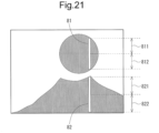
- a streak defect denoted by reference numeral 60 in Fig. 6 is detected by an inspection process to detect a defect (a defect in the print image) by the image inspection device 300.
- a process for correcting the image based on the print data while setting the nozzle that is assumed to have caused the streak defect as a correction target nozzle so as to obtain the print image obtained by removing the influence of the ejection defect of the correction target nozzle is referred to as a "defect correction process".
- the four nozzles extracted as the defective nozzle candidates are referred to as a "first nozzle”, a “second nozzle”, a “third nozzle”, and a “fourth nozzle”.
- the defect correction process is performed with the first nozzle set as the correction target nozzle for the partial region 61
- the defect correction process is performed with the second nozzle set as the correction target nozzle for the partial region 62
- the defect correction process is performed with the third nozzle set as the correction target nozzle for the partial region 63
- the defect correction process is performed with the fourth nozzle set as the correction target nozzle for the partial region 64.
- a print result as shown in Fig. 8 is obtained after the defect correction process. According to the print result shown in Fig.
- Fig. 9 is a functional block diagram showing a functional configuration related to the defective nozzle detection process in the present embodiment.
- the print controller 100 is provided with an original image storage unit 110, a first correction unit 120, and a second correction unit 130 as functional components related to the defective nozzle detection process.
- the image inspection computer 320 is provided with a correct data creation unit 321, a defect detection unit 322, a defective nozzle position candidate extraction unit 323, a defect color identification unit 324, and a defective nozzle identification unit 325 as functional components related to the defective nozzle detection process.
- a correct data creation unit 321 a defect detection unit 322, a defective nozzle position candidate extraction unit 323, a defect color identification unit 324, and a defective nozzle identification unit 325 as functional components related to the defective nozzle detection process.
- the original image storage unit 110 stores a user image that is an image to be printed.
- This user image is an image before being subjected to a halftone process and corresponds to print data transmitted from the print data generation device 40.
- the "user image” refers to, for example, an image specified by the user for printing an image desired by a user and is synonymous with a "real image” such as a product image that the user desires to print or a test image for test printing of the product image in advance.
- the user image stored in the original image storage unit 110 is provided from the print controller 100 to the correct data creation unit 321. Then, the correct data creation unit 321 creates a correct image in RGB format from the user image in CMYK format.
- the defect detection unit 322 performs an inspection process for detecting a defect included in a captured image obtained by capturing a print image by the imaging unit 310. This inspection process is performed by comparing the captured image with the correct image created by the correct data creation unit 321. In this regard, with the captured image being RGB format data, the correct image in the RGB format is created by the correct data creation unit 321 as described above. Note that the inspection process by the defect detection unit 322 is also performed by comparing the captured image of the print image based on the user image with the correct image, or is also performed by comparing the captured image of the print image based on a corrected image to be described later with the correct image.
- the defective nozzle position candidate extraction unit 323 extracts a candidate for the position (position candidate) of the defective nozzle from the positions of the plurality of nozzles provided in the printing unit 205 based on the position (the position in the captured image: coordinates in the main scanning direction) of the defect detected in the inspection process by the defect detection unit 322.
- the defective nozzle position candidate extraction unit 323 extracts N position candidates (N is an integer of 2 or more). In other words, the defective nozzle position candidate extraction unit 323 extracts N nozzles as defective nozzle candidates from among the plurality of nozzles provided in the printing unit 205.
- the defect color identification unit 324 identifies a color of ink ejected by a print head that includes a defective nozzle among the black print head 25K, the cyan print head 25C, the magenta print head 25M, and the yellow print head 25Y.
- the defect color identification unit 324 identifies a color on the basis of a difference in average values of R (red) color values, a difference in average values of G (green) color values, and an average value of B (blue) color values in a region where a defect is detected by the inspection process performed on the basis of the user image, between a captured image based on the user image and a correct image corresponding to the user image.
- the defect color identification unit 324 narrows down the color based on the data of a portion corresponding to the N position candidates in the user image, and further identifies the color based on the data of the portion corresponding to the N position candidates in the captured image and the correct image.
- the color identified by the defect color identification unit 324 is referred to as a "defect color”.
- the information on the position candidate extracted by the defective nozzle position candidate extraction unit 323 and the information on the defect color identified by the defect color identification unit 324 are provided from the image inspection computer 320 to the first correction unit 120. Then, the first correction unit 120 generates the corrected image by performing the defect correction process described above on the user image while sequentially setting only the N nozzles (the nozzles extracted as the defective nozzle candidates by the defective nozzle position candidate extraction unit 323) among the plurality of nozzles provided in the printing unit 205 as the correction target nozzles one by one based on the information on the position candidate and the information on the defect color.
- an image (corrected user image) obtained by the second correction unit 130 performing the defect correction process (the defect correction process for removing the influence of the ejection defect of the defective nozzle) on the user image is provided to the first correction unit 120, and the first correction unit 120 performs the defect correction process on the corrected user image to generate a corrected image.
- the first correction unit 120 includes an association unit 122.
- the association unit 122 associates N nozzles as defective nozzle candidates with N partial regions included in the user image. At that time, N partial regions are set such that each partial region includes the position of the defect detected by the inspection process performed by comparing the captured image of the print image based on the user image with the correct image.
- the defect correction process by the first correction unit 120 is performed by setting a different nozzle among the N nozzles as the correction target nozzle for each of the N partial regions.
- Correction position information indicating which nozzle has been set as the correction target nozzle at which position (region) in performing the defect correction process is provided from the print controller 100 to the defective nozzle identification unit 325. Then, the defective nozzle identification unit 325 identifies the defective nozzle on the basis of the position (the position in the captured image: coordinates in the main scanning direction) of the defect detected in the inspection process performed by comparing the captured image of the print image based on the corrected image with the correct image, and the correction position information.
- the information on the defective nozzle identified by the defective nozzle identification unit 325 is provided from the image inspection computer 320 to the second correction unit 130. Then, the second correction unit 130 performs the defect correction process on the user image so as to obtain a print image from which the influence of the ejection defect of the defective nozzle has been removed. As a result, the corrected user image described above is obtained. After all the defective nozzles are identified, printing is performed by the printing unit 205 based on the corrected user image generated by the second correction unit 130.
- the print controller 100 is also provided with a component for performing the halftone process so that the image data after the halftone process is provided to the printing unit 205.
- this component is omitted in Fig. 9 .
- Fig. 10 is a flowchart showing a schematic procedure of the defective nozzle detection process. This defective nozzle detection process is performed repeatedly, and hence the procedure described here is a procedure of a process for one page.
- a correction process by the second correction unit 130 is performed (step S22). Specifically, the defect correction process is performed on the user image so as to obtain the print image from which the influence of the ejection defect of the defective nozzle identified in step S21 has been removed. As a result, the corrected user image described above is obtained. After a defective nozzle corresponding to a certain streak defect is identified in step S21, in a case where the defect correction process is performed by the first correction unit 120 to identify a defective nozzle having caused another streak defect, the corrected user image generated in step S22 is provided to the first correction unit 120. After all the defective nozzles are identified, printing is performed by the printing unit 205 based on the corrected user image generated in step S22.
- the first printing step is implemented by step S12
- the first imaging step is implemented by step S13
- the first defect detection step is implemented by step S14
- the defective nozzle position candidate extraction step is implemented by step S15
- the defect color identification step is implemented by step S16
- the defect correction step is implemented by step S17
- the second printing step is implemented by step S18
- the second imaging step is implemented by step S19
- the second defect detection step is implemented by step S20
- the defective nozzle identification step is implemented by step S21.
- Fig. 11 is a flowchart showing a detailed procedure of the defective nozzle position candidate extraction process.
- the correct image original image
- the correct image is divided into a plurality of blocks each having a predetermined range, and a process called "swing comparison" for comparing the correct image and the captured image while slightly shifting the relative positional relationship between the correct image and the captured image is performed for each block (step S150).
- This process is performed to align the correct image and the captured image because there is a gap in a position where printing is performed on the print paper.
- step S150 for example, as shown in Fig.
- nine cases are prepared concerning the relative positional relationship between the correct image 71 and the captured image 72, and alignment corresponding to a case where a difference in color values (RGB values) between the correct image 71 and the captured image 72 is minimized is performed.
- the position (coordinates) of the defect in the captured image is converted into a position (coordinates) on the user image (step S151).
- N position candidates are obtained as candidates for the position of the defective nozzle based on the converted coordinates (coordinates in the main scanning direction) (step S152). That is, the position of the defective nozzle candidate is identified.
- information that associates the coordinates in the main scanning direction on the user image with the position (coordinates in the main scanning direction) of each nozzle is held in advance, and based on this information, the position (coordinates) of the defective nozzle candidate is identified from the coordinates obtained in step S151.
- step S153 After the position of the defective nozzle candidate is identified, it is determined whether or not the position (coordinates in the main scanning direction) of the defective nozzle candidate has already been held in a list (hereinafter referred to as a "defect list") that holds information on streak defects (step S153). As a result, when the coordinates in the main scanning direction are held in the defect list, the processing proceeds to step S154, and when the coordinates in the main scanning direction are not held in the defect list, the processing proceeds to step S155.
- a list hereinafter referred to as a "defect list”
- step S154 the information on the length of the corresponding streak defect in the defect list is corrected.
- step S155 the information on the corresponding streak defect is added to the defect list.
- Concerning steps S154 and S155 since the processing of step S152 is performed for each block, for example, in a case where a streak defect has occurred across two blocks, the information on the streak defect is added to the defect list during the processing of the first block, and the information on the length of the streak defect in the defect list is corrected during the processing of the second block.
- step S154 or step S155 ends, the defective nozzle position candidate extraction process ends. For example, in a case in which two streak defects have occurred as shown in Fig. 13 with respect to the processing target page, the information on the two streak defects is held in the defect list as shown in Fig. 14 at the time when the defective nozzle position candidate extraction process ends.
- Fig. 15 is a flowchart showing a detailed procedure of the defect color identification process.
- the defect color identification process is started, first, it is determined whether or not the defect information (the information on the position of the defective nozzle candidate and the information on the defect color) has already been transmitted to the print controller 100 (step S161). As a result, when the defect information has been transmitted to the print controller 100, the defect color identification process ends, and when the defect information has not been transmitted to the print controller 100, the processing proceeds to processing of a first loop.
- the defect information is transmitted to the print controller 100 during the processing of the first page, and the defect color identification process ends without the defect information being transmitted to the print controller 100 during the processing of the second page.
- step S162 a target color narrowing process for narrowing down the color determined as the candidate color of the defect color from among black, cyan, magenta, and yellow (a process for narrowing down the target color of processing of a second loop) is performed based on the user image and the information on the position of the defective nozzle candidate. Note that details of the target color narrowing process will be described later.
- step S163 it is determined whether or not the colors excluded from the defect color candidates by the target color narrowing process are three colors.
- the processing proceeds to step S166, and when the colors excluded from the defect color candidates are not three colors, the processing proceeds to the processing of the second loop.
- the colors excluded from the defect color candidates are three colors, the remaining color among black, cyan, magenta, and yellow is determined as the defect colors.
- step S164 a defect analysis process for analyzing defects in detail based on the correct image and the captured image is performed. Note that details of the defect analysis process will be described later.
- the defect color is determined based on the result of the defect analysis process (step S165). In this regard, as will be described later, in the processing of the second loop, the defect color is determined for each unit region in the region corresponding to the streak defect. Then, in step S165, the color determined as the defect color most frequently in the processing of the second loop is determined as the final defect color.
- step S166 defect information is transmitted from the image inspection computer 320 to the print controller 100 based on the result of the defective nozzle position candidate extraction process described above and the result of step S165. Thereafter, the defect information is stored in the image inspection computer 320 (e.g., the auxiliary storage device 521) (step S167), and the defect color identification process ends.
- the defect correction process is performed by the first correction unit 120, a nozzle that ejects ink of a color (defect color) identified by the defect color identification process is set as a correction target nozzle.
- step S1642 an average value of color values of a plurality of pixels included in a unit region is calculated for each of R, G, and B (step S1642). That is, in step S1642, the average value for R, the average value for G, and the average value for B are calculated based on the correct image.
- step S1643 a difference between the average value calculated in step S1641 and the average value calculated in step S1642 is calculated as a variation amount (step S1643).
- a defect color is determined for a unit region to be processed (step S1644).
- a color for which the variation amount calculated in step S1643 is equal to or larger than a predetermined threshold is treated as "variation amount: large”. How to determine the defect color based on the defect color determination table will be described below.
- Fig. 19 is a diagram schematically showing an example of a defect color determination table.
- the defect color determination table holds, for each combination of two or more colors of black, cyan, magenta, and yellow, information for identifying a color to be determined as the defect color in step S1644 from among the process colors (black, cyan, magenta, and yellow) depending on the result obtained in step S1643 for each of R, G, and B.
- a portion denoted by reference numeral 73 stores possible combinations of colors not excluded from the target colors in the processing of the first loop.
- a portion denoted by reference numeral 74 stores information corresponding to the variation amount for each of R, G, and B.
- a portion denoted by reference numeral 75 stores information on a color to be determined as the defect color.
- a circle mark in the portion denoted by reference numeral 74 indicates that the corresponding color is "variation amount: large”
- a blank portion in the portion denoted by reference numeral 74 indicates that the corresponding color is not “variation amount: large”
- a hyphen in the portion denoted by reference numeral 74 indicates that there is no case where the corresponding color is "variation amount: large”
- a hyphen in the portion denoted by reference numeral 75 indicates that the corresponding case does will not appear.
- "X" in the portion denoted by reference numeral 75 indicates that the defect color should be determined assuming that only a color having the largest variation amount among a plurality of colors having "variation amount: large” is "variation amount: large”.
- the defect color determination table shown in Fig. 19 is prepared and no color was excluded from the target colors (defect color candidates) in the processing of the first loop.
- the target colors are four colors of cyan (C), magenta (M), yellow (Y), and black (K).
- black (K) is determined as the defect color with reference to a portion indicated by an arrow denoted by reference numeral 76.
- the defect color determination table shown in Fig. 19 is prepared and that black (K) was excluded from the target colors (defect color candidates) in the processing of the first loop.
- the target colors are three colors of cyan (C), magenta (M), and yellow (Y).
- magenta (M) is determined as the defect color by referring to a portion indicated by an arrow denoted by reference numeral 77.
- the defect color determination table shown in Fig. 19 is prepared and that no color was excluded from the target colors (defect color candidates) in the processing of the first loop.
- the target colors are four colors of cyan (C), magenta (M), yellow (Y), and black (K).
- G and B are "variation amount: large", and the variation amount of G is larger than that of B, magenta (M) is determined as the defect color by referring to a portion indicated by an arrow denoted by reference numeral 78 and a portion indicated by an arrow denoted by reference numeral 79.
- step S1644 the defect color is determined using the defect color determination table.
- the defect analysis process is repeated a plurality of times. Therefore, the number of determination results (defect color determination results) equal to the number of times the defect analysis process is repeated is obtained. Then, as described above, in step S165 of Fig. 15 , the color determined as the defect color most frequently in step S1644 is determined as the final defect color.
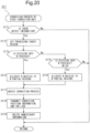
- Fig. 20 is a flowchart showing a detailed procedure of the correction process performed by the first correction unit 120. After the correction process is started, first, it is determined whether or not there is defect information (the information on the position of the defective nozzle candidate and the information on the defect color) concerning the processing target page (step S171). As a result, when there is defect information, the processing proceeds to step S172, and when there is no defect information, the correction process ends.
- defect information the information on the position of the defective nozzle candidate and the information on the defect color
- step S172 for the processing target page, a region in which the density value of the defect color satisfies a predetermined condition in the region corresponding to the position candidate (candidate for the position of the defective nozzle) extracted in the defective nozzle position candidate extraction process is set as the processing target region (step S172).
- a region in which the ink of the defect color has been applied at such a density that it can be determined whether or not the effect of correction for removing the influence of the ejection defect of the nozzle has been obtained from the corrected image is set as the processing target region.
- step S173 it is determined whether or not the size of each partial region obtained by dividing the processing target region set in step S172 into N (the number of defective nozzle candidates) regions is equal to or larger than the size of a region (hereinafter referred to as a "minimum inspectable region") required for the image inspection computer 320 to detect a defect (step S173).
- a region hereinafter referred to as a "minimum inspectable region"
- the processing proceeds to step S174, and when the size of each partial region is not equal to or larger than the size of the minimum inspectable region, the processing proceeds to step S175.
- the size of the minimum inspectable region depends on the capability of the image inspection computer 320.
- step S174 the N defective nozzle candidates are associated with N partial regions obtained by dividing the processing target region into N regions. In this manner, the N defective nozzle candidates and the N partial regions are associated on a one-to-one basis.
- step S175 it is determined whether or not the processing target region can be divided into M (M is an integer less than N) partial regions such that the size of each divided partial region is equal to or larger than the size of the minimum inspectable region.
- M is an integer less than N
- the processing proceeds to step S176, and when the division is not possible, the correction process ends.
- step S176 M nozzles among the N nozzles regarded as defective nozzle candidates are associated with M partial regions obtained by dividing the processing target region into M regions.
- step S177 the defect correction process is performed on the user image (step S177).
- the defect correction process is performed while setting a different nozzle among the N nozzles (nozzles regarded as defective nozzle candidates) as the correction target nozzle for each of the N partial regions.
- the defect correction process is performed while setting a different nozzle of the M nozzles (nozzles regarded as defective nozzle candidates) as the correction target nozzle for each of the M partial regions.
- correction position information (information indicating which nozzle has been set as the correction target nozzle at which position (region) in performing the defect correction process) is transmitted from the print controller 100 to the image inspection computer 320 (step S178). Thereafter, unnecessary defect information and the like are deleted (step S179). Thus, the correction process by the first correction unit 120 ends.
- the processed image data (the data of the user image transmitted from the print controller 100 to the image inspection computer 320) and the correction position information are deleted (step S216).
- the defective nozzle identification process ends.
- the present invention is applied to the inkjet printer 10 including the print heads (ink ejection units) 25K, 25C, 25M, and 25Y of four colors of black (K), cyan (C), magenta (M), and yellow (Y) has been described.
- the present invention is not limited thereto, and even when the present invention is applied to a printer that performs printing using print heads of five or more colors, a defect color can be identified by performing a process similar to the defect color identification process described above.
- the inkjet printer 10 using aqueous ink has been adopted.
- the present invention is not limited thereto, and for example, an inkjet printer using ultraviolet (UV) ink (ultraviolet curing ink) such as an inkjet printer for label printing may be adopted.
- an ultraviolet irradiation unit that cures the UV ink on the print paper PA by ultraviolet irradiation is provided inside the printing mechanism 201 (cf. Fig. 2 ) instead of the drying unit 206.
Landscapes
- Engineering & Computer Science (AREA)
- Quality & Reliability (AREA)
- Ink Jet (AREA)
Claims (11)
- Système d'impression comprenant :un mécanisme de transport (203, 204, 207) pour transporter un support d'impression ;une unité d'impression (205) qui a une pluralité de buses et est configurée pour effectuer l'impression d'une image d'impression à une première résolution sur le support d'impression en éjectant de l'encre de chacune de la pluralité de buses, la pluralité de buses étant agencée dans une direction de balayage principale qui est perpendiculaire à une direction dans laquelle le mécanisme de transport (203, 204, 207) transporte le support d'impression ;une unité d'imagerie (310) configurée pour capturer l'image d'impression imprimée sur le support d'impression par l'unité d'impression (205) à une deuxième résolution inférieure à la première résolution ;une unité de détection de défauts (322) configurée pour effectuer un processus d'inspection afin de détecter un défaut de strie inclus dans une image capturée obtenue en capturant l'image d'impression par l'unité d'imagerie (310) ;une unité d'extraction de candidats de position de buse défectueuse (323) configurée pour extraire N candidats de position, N étant un entier de 2 ou plus, à partir de positions de la pluralité de buses en tant que candidates pour une position d'une buse défectueuse qui est une buse ayant un défaut d'éjection, sur la base de coordonnées dans la direction de balayage principale du défaut de stries détecté par le processus d'inspection dans l'image capturée, les N candidats de position ayant des positions différentes par rapport à la direction de balayage principale ;une unité de correction de défaut (120) configurée pour effectuer, sur une image utilisateur, un processus de correction de défaut pour supprimer une influence d'un défaut d'éjection d'une buse définie comme une buse cible de correction afin de générer une image corrigée, l'image utilisateur étant une image à imprimer ; etune unité d'identification de buse défectueuse (325) configurée pour identifier la buse défectueuse parmi N buses correspondant respectivement aux N candidats de position,dans lequelaprès que l'impression par l'unité d'impression (205), la capture de l'image d'impression par l'unité d'imagerie (310) et le processus d'inspection par l'unité de détection de défauts (322) ont été effectués sur la base de l'image utilisateur, les N candidats de position sont extraits par l'unité d'extraction des candidats de position de buse défectueuse (323),l'unité de correction de défaut (120) effectue le processus de correction de défaut tout en définissant séquentiellement chacune des seulement N buses parmi la pluralité de buses comme la buse cible de correction une par une,après que l'image corrigée a été générée par l'unité de correction de défaut (120), l'impression par l'unité d'impression (205), la capture de l'image d'impression par l'unité d'imagerie (310) et le processus d'inspection par l'unité de détection des défauts (322) sont effectués sur la base de l'image corrigée,l'unité d'identification de buse défectueuse (325) identifie la buse défectueuse en fonction d'une position du défaut de strie détecté par le processus d'inspection effectué sur la base de l'image corrigée, dans l'image capturée,l'unité de correction de défaut (120) comprend une unité d'association (122) qui associe les N buses à N régions partielles incluses dans l'image utilisateur, les N régions partielles ayant les mêmes positions par rapport à la direction de balayage principale,chacune des N régions partielles comprend la position du défaut de strie détecté par le processus d'inspection effectué sur la base de l'image utilisateur,l'unité de correction de défaut (120) effectue le processus de correction de défaut tout en définissant une buse différente parmi les N buses comme la buse cible de correction pour chacune des N régions partielles,l'unité d'identification de buse défectueuse (325) identifie, comme la buse défectueuse, une buse associée à une région partielle dans laquelle aucun défaut de strie n'est détecté par le processus d'inspection effectué sur la base de l'image corrigée, parmi les N régions partielles, etl'unité d'extraction de candidats de position de buse défectueuse (323) convertit les coordonnées dans la direction de balayage principale, dans l'image capturée, du défaut de strie détecté par le processus d'inspection effectué sur la base de l'image utilisateur en coordonnées dans la direction de balayage principale sur l'image utilisateur et extrait les N candidats de position à partir des positions de la pluralité de buses sur la base des coordonnées converties.
- Système d'impression selon la revendication 1, dans lequell'unité d'impression (205) comprend une pluralité d'unités d'éjection d'encre (25K, 25C, 25M et 25Y) qui éjectent des encres de différentes couleurs à partir de buses,le système d'impression comprend en outre une unité d'identification de couleur défectueuse (324) configurée pour identifier une couleur d'encre éjectée par une unité d'éjection d'encre qui comprend la buse défectueuse parmi la pluralité d'unités d'éjection d'encre (25K, 25C, 25M et 25Y), etlors de l'exécution du processus de correction de défaut, l'unité de correction de défaut (120) définit, comme la buse cible de correction, une buse qui éjecte de l'encre d'une couleur défectueuse qui est la couleur identifiée par l'unité d'identification de couleur défectueuse (324).
- Système d'impression selon la revendication 2, dans lequella pluralité d'unités d'éjection d'encre (25K, 25C, 25M et 25Y) comprend une unité d'éjection d'encre noire (25K) qui éjecte une encre noire, une unité d'éjection d'encre cyan (25C) qui éjecte une encre cyan, une unité d'éjection d'encre magenta (25M) qui éjecte une encre magenta, et une unité d'éjection d'encre jaune (25Y) qui éjecte une encre jaune, etl'unité d'identification de couleur défectueuse (324) identifie la couleur défectueuse parmi les couleurs, à l'exception d'une couleur d'une encre, dont la quantité à éjecter à la position du défaut de strie détecté par le processus d'inspection effectué sur la base de l'image utilisateur est égale ou inférieure à un seuil prédéterminé, parmi l'encre noire, l'encre cyan, l'encre magenta et l'encre jaune.
- Système d'impression selon la revendication 2 ou 3, dans lequel l'unité d'identification de couleur défectueuse (324) identifie la couleur défectueuse sur la base d'une différence entre les valeurs moyennes des valeurs de couleur rouge, d'une différence entre les valeurs moyennes des valeurs de couleur verte et d'une différence entre les valeurs moyennes des valeurs de couleur bleue, dans une région où un défaut de strie est détecté par le processus d'inspection effectué sur la base de l'image utilisateur, entre l'image capturée sur la base de l'image utilisateur et une image correcte correspondant à l'image utilisateur.
- Système d'impression selon l'une quelconque des revendications 2 à 4, dans lequel l'unité d'association (122) définit, en tant qu'une région cible de traitement, une région dans laquelle une valeur de densité de la couleur défectueuse satisfait à une condition prédéterminée parmi les régions correspondant aux N candidats de position, et l'unité d'association associe les N buses aux N régions partielles dans la région cible de traitement.
- Système d'impression selon la revendication 5, dans lequeldans un cas où chaque région partielle a une taille égale ou supérieure à une taille d'une région requise pour la détection d'un défaut de strie par le processus d'inspection lorsque la région cible de traitement dans une page est divisée en N régions partielles, l'unité d'association (122) associe les N buses aux N régions partielles obtenues en divisant la région cible de traitement dans ladite une page en N régions, etdans un cas où chaque région partielle a une taille inférieure à la taille de la région requise pour la détection d'un défaut de strie par le processus d'inspection lorsque la région cible de traitement dans une page est divisée en N régions partielles, l'unité d'association (122) divise la région cible de traitement dans ladite une page en M régions partielles, M étant un nombre entier inférieur à N, dans une plage dans laquelle une taille de chaque région partielle après division est égale ou supérieure à la taille de la région requise pour la détection d'un défaut de strie par le processus d'inspection, et l'unité d'association associe M buses parmi les N buses aux M régions partielles.
- Système d'impression selon l'une quelconque des revendications 1 à 6, dans lequell'image utilisateur est une image de deux pages ou plus, etl'unité d'association (122) disperse les N régions partielles en une pluralité de pages et associe les N buses aux N régions partielles.
- Système d'impression selon la revendication 7, dans lequel une taille de chacune des N régions partielles est égale ou supérieure à une taille d'une région requise pour la détection d'un défaut de strie par le processus d'inspection.
- Procédé de détection de buse défectueuse dans un système d'impression comprenant un mécanisme de transport (203, 204, 207) pour transporter un support d'impression, une unité d'impression (205) qui a une pluralité de buses et imprime une image d'impression à une première résolution sur le support d'impression en éjectant de l'encre de chacune de la pluralité de buses, et une unité de d'imagerie (310) qui capture l'image d'impression imprimée sur le support d'impression par l'unité d'impression (205) à une deuxième résolution inférieure à la première résolution, la pluralité de buses étant agencée dans une direction de balayage principale qui est perpendiculaire à une direction dans laquelle le mécanisme de transport (203, 204, 207) transporte le support d'impression, le procédé de détection de buses défectueuses comprenant :une première étape d'impression (S12) consistant à imprimer une image utilisateur à la première résolution par l'unité d'impression ;une première étape d'imagerie (S13) consistant à imager une image d'impression obtenue lors de la première étape d'impression (S12) à la deuxième résolution ;une première étape de détection de défaut (S14) consistant à détecter un défaut de strie inclus dans une première image capturée obtenue lors de la première étape d'imagerie (S13) ;une étape d'extraction de candidats de position de buse défectueuse (S15) consistant à extraire N candidats de position, N étant un entier de 2 ou plus, à partir des positions de la pluralité de buses en tant que candidates pour une position d'une buse défectueuse qui est une buse ayant un défaut d'éjection, sur la base de coordonnées dans la direction de balayage principale du défaut de strie détecté dans la première étape de détection de défaut (S14) dans la première image capturée, les N candidats de position ayant des positions différentes par rapport à la direction de balayage principale ;une étape de correction de défaut (S17) consistant à effectuer, sur l'image utilisateur, un processus de correction de défaut pour supprimer une influence d'un défaut d'éjection d'une buse définie comme une buse cible de correction afin de générer une image corrigée ;une deuxième étape d'impression (S18) consistant à imprimer l'image corrigée à la première résolution par l'unité d'impression (205) ;une deuxième étape d'imagerie (S19) consistant à imager une image d'impression obtenue lors de la deuxième étape d'impression (S18) à la deuxième résolution ;une deuxième étape de détection de défaut (S20) consistant à détecter un défaut de strie inclus dans une deuxième image capturée obtenue lors de la deuxième étape d'imagerie (S19) ; etune étape d'identification de buse défectueuse (S21) consistant à identifier la buse défectueuse parmi N buses correspondant respectivement aux N candidats de position sur la base d'une position du défaut de strie détecté lors de la deuxième étape de détection de défaut (S20) dans la deuxième image capturée,dans lequel, dans l'étape de correction de défaut (S17), le processus de correction de défaut est effectué tout en définissant séquentiellement chacune des N buses seulement parmi la pluralité de buses comme la buse cible de correction, une par une,l'étape de correction de défaut (S17) comprend une étape d'association (S173 à S176) consistant à associer les N buses aux N régions partielles incluses dans l'image utilisateur, les N régions partielles ayant les mêmes positions par rapport à la direction de balayage principale,chacune des N régions partielles comprend une position d'un défaut de strie détecté lors de la première étape de détection de défaut (S14),dans l'étape de correction de défaut (S17), le processus de correction de défaut est effectué tout en définissant une buse différente parmi les N buses comme la buse cible de correction pour chacune des N régions partielles,dans l'étape d'identification de buse défectueuse (S21), une buse associée à une région partielle dans laquelle aucun défaut de strie n'est détecté dans la deuxième étape de détection de défaut (S20), parmi les N régions partielles, est spécifiée comme la buse défectueuse,dans l'étape d'extraction de candidats de position de buse défectueuse (S15), les coordonnées dans la direction de balayage principale, dans la première image capturée, du défaut de strie détecté dans la première étape de détection de défaut (S14) sont converties en coordonnées dans la direction de balayage principale sur l'image utilisateur, et les N candidats de position sont extraits des positions de la pluralité de buses sur la base des coordonnées converties.
- Procédé de détection de buse défectueuse selon la revendication 9, dans lequell'unité d'impression (205) comprend une pluralité d'unités d'éjection d'encre (25K, 25C, 25M et 25Y) qui éjectent des encres de différentes couleurs à partir de buses,le procédé de détection de buse défectueuse comprend en outre une étape d'identification de couleur défectueuse (S16) consistant à identifier une couleur d'encre éjectée par une unité d'éjection d'encre qui comprend la buse défectueuse parmi la pluralité d'unités d'éjection d'encre (25K, 25C, 25M et 25Y), etdans l'étape de correction de défaut (S17), lorsque le processus de correction de défaut est exécuté, une buse qui éjecte de l'encre d'une couleur défectueuse qui est la couleur identifiée dans l'étape d'identification de couleur défectueuse (S16) est définie comme la buse cible de correction.
- Procédé de détection de buse défectueuse selon la revendication 9 ou 10, dans lequell'image utilisateur est une image de deux pages ou plus, etdans l'étape d'association (S173 à S176), les N régions partielles sont dispersées dans une pluralité de pages, et les N buses sont associées aux N régions partielles.
Applications Claiming Priority (1)
| Application Number | Priority Date | Filing Date | Title |
|---|---|---|---|
| JP2022034059A JP2023129792A (ja) | 2022-03-07 | 2022-03-07 | 印刷システムおよび欠陥ノズル検出方法 |
Publications (2)
| Publication Number | Publication Date |
|---|---|
| EP4242002A1 EP4242002A1 (fr) | 2023-09-13 |
| EP4242002B1 true EP4242002B1 (fr) | 2025-04-09 |
Family
ID=85122326
Family Applications (1)
| Application Number | Title | Priority Date | Filing Date |
|---|---|---|---|
| EP23153539.4A Active EP4242002B1 (fr) | 2022-03-07 | 2023-01-26 | Système d'impression et procédé de détection de buse défectueuse |
Country Status (3)
| Country | Link |
|---|---|
| US (1) | US12285943B2 (fr) |
| EP (1) | EP4242002B1 (fr) |
| JP (1) | JP2023129792A (fr) |
Families Citing this family (2)
| Publication number | Priority date | Publication date | Assignee | Title |
|---|---|---|---|---|
| US12459264B2 (en) | 2023-03-03 | 2025-11-04 | Ricoh Company, Ltd. | Printhead maintenance for recommending printhead replacement |
| EP4454897A1 (fr) * | 2023-04-17 | 2024-10-30 | Unilin, BV | Procédé de formation d'un substrat décoratif pour panneau décoratif et procédé de formation d'un panneau décoratif |
Family Cites Families (8)
| Publication number | Priority date | Publication date | Assignee | Title |
|---|---|---|---|---|
| JPH0645060B2 (ja) | 1986-10-30 | 1994-06-15 | 旭テック株式会社 | カムシヤフト用鋳型装置 |
| US7347523B2 (en) | 2003-08-04 | 2008-03-25 | Fujifilm Corporation | Image recording apparatus and method for determining defective image-recording elements |
| JP3820506B2 (ja) | 2003-08-04 | 2006-09-13 | 富士写真フイルム株式会社 | 画像記録装置 |
| US8646862B2 (en) | 2012-02-28 | 2014-02-11 | Xerox Corporation | System and method for detection and compensation of inoperable inkjets in an inkjet printing apparatus |
| JP5971151B2 (ja) * | 2013-02-20 | 2016-08-17 | 富士ゼロックス株式会社 | 画像形成装置及びプログラム |
| JP6472058B2 (ja) * | 2016-03-29 | 2019-02-20 | 富士フイルム株式会社 | 画像形成装置及び画像補正方法 |
| JP6576316B2 (ja) | 2016-09-27 | 2019-09-18 | 富士フイルム株式会社 | 画像検査装置及び方法、プログラム並びにインクジェット印刷システム |
| JP6945060B2 (ja) | 2018-03-28 | 2021-10-06 | 富士フイルム株式会社 | 画像形成装置及び方法、異常ノズル検出方法並びに印刷物の製造方法 |
-
2022
- 2022-03-07 JP JP2022034059A patent/JP2023129792A/ja active Pending
-
2023
- 2023-01-25 US US18/159,324 patent/US12285943B2/en active Active
- 2023-01-26 EP EP23153539.4A patent/EP4242002B1/fr active Active
Also Published As
| Publication number | Publication date |
|---|---|
| JP2023129792A (ja) | 2023-09-20 |
| US20230278329A1 (en) | 2023-09-07 |
| EP4242002A1 (fr) | 2023-09-13 |
| US12285943B2 (en) | 2025-04-29 |
Similar Documents
| Publication | Publication Date | Title |
|---|---|---|
| EP3305532B1 (fr) | Dispositif d'inspection d'image, procédé d'inspection d'image, programme et système d'impression à jet d'encre | |
| EP3300907B1 (fr) | Procédé d'inspection d'image, dispositif d'inspection d'image, programme et système d'enregistrement d'image | |
| JP7476088B2 (ja) | 印刷不良検出システム、及び記憶媒体 | |
| US8562099B2 (en) | Ink jet recording apparatus and method for detecting faulty discharge in ink jet recording apparatus | |
| EP4242002B1 (fr) | Système d'impression et procédé de détection de buse défectueuse | |
| JP6472058B2 (ja) | 画像形成装置及び画像補正方法 | |
| US9387711B2 (en) | Image recording apparatus and method | |
| US12182989B2 (en) | Printed matter inspection device, printed matter inspection method, program, and printing apparatus | |
| WO2020179742A1 (fr) | Procédé d'inspection, programme, dispositif d'inspection et dispositif d'impression | |
| WO2019188911A1 (fr) | Dispositif et procédé de formation d'image, procédé de détection de buse anormale et procédé de fabrication de matière imprimée | |
| JP6066395B2 (ja) | 画像検査装置及び画像検査方法 | |
| JP2011209105A (ja) | 画像検査装置および印刷装置、並びに、画像検査方法 | |
| JP2016074187A (ja) | テスト画像、テスト画像形成システム、テスト画像形成方法、テスト画像形成プログラム、記憶媒体、記憶媒体、異常記録素子検出システム、異常記録素子検出方法、異常記録素子検出プログラム、及び記憶媒体 | |
| JP5699051B2 (ja) | 画像検査装置および画像記録装置、並びに、画像検査方法 | |
| JP7126477B2 (ja) | 画像検査方法及び装置、プログラム並びに画像記録システム | |
| US12508817B2 (en) | Printing device inline inspection system and methods | |
| JP2010111031A (ja) | 印刷検査装置及び印刷検査方法 | |
| EP4342678A1 (fr) | Appareil d'impression et procédé d'impression | |
| US20250291526A1 (en) | Automatic inspection template generation mechanism | |
| US20230185499A1 (en) | Information processing apparatus, information processing method, printing system, and storage medium | |
| EP4691779A1 (fr) | Imprimante, procédé de détection de défaillance d'éjection et programme de détection de défaillance d'éjection |
Legal Events
| Date | Code | Title | Description |
|---|---|---|---|
| PUAI | Public reference made under article 153(3) epc to a published international application that has entered the european phase |
Free format text: ORIGINAL CODE: 0009012 |
|
| STAA | Information on the status of an ep patent application or granted ep patent |
Free format text: STATUS: THE APPLICATION HAS BEEN PUBLISHED |
|
| AK | Designated contracting states |
Kind code of ref document: A1 Designated state(s): AL AT BE BG CH CY CZ DE DK EE ES FI FR GB GR HR HU IE IS IT LI LT LU LV MC ME MK MT NL NO PL PT RO RS SE SI SK SM TR |
|
| STAA | Information on the status of an ep patent application or granted ep patent |
Free format text: STATUS: REQUEST FOR EXAMINATION WAS MADE |
|
| 17P | Request for examination filed |
Effective date: 20240313 |
|
| RBV | Designated contracting states (corrected) |
Designated state(s): AL AT BE BG CH CY CZ DE DK EE ES FI FR GB GR HR HU IE IS IT LI LT LU LV MC ME MK MT NL NO PL PT RO RS SE SI SK SM TR |
|
| GRAP | Despatch of communication of intention to grant a patent |
Free format text: ORIGINAL CODE: EPIDOSNIGR1 |
|
| STAA | Information on the status of an ep patent application or granted ep patent |
Free format text: STATUS: GRANT OF PATENT IS INTENDED |
|
| INTG | Intention to grant announced |
Effective date: 20241104 |
|
| GRAS | Grant fee paid |
Free format text: ORIGINAL CODE: EPIDOSNIGR3 |
|
| GRAA | (expected) grant |
Free format text: ORIGINAL CODE: 0009210 |
|
| STAA | Information on the status of an ep patent application or granted ep patent |
Free format text: STATUS: THE PATENT HAS BEEN GRANTED |
|
| AK | Designated contracting states |
Kind code of ref document: B1 Designated state(s): AL AT BE BG CH CY CZ DE DK EE ES FI FR GB GR HR HU IE IS IT LI LT LU LV MC ME MK MT NL NO PL PT RO RS SE SI SK SM TR |
|
| REG | Reference to a national code |
Ref country code: GB Ref legal event code: FG4D |
|
| REG | Reference to a national code |
Ref country code: CH Ref legal event code: EP |
|
| REG | Reference to a national code |
Ref country code: DE Ref legal event code: R096 Ref document number: 602023002754 Country of ref document: DE |
|
| REG | Reference to a national code |
Ref country code: IE Ref legal event code: FG4D |
|
| P01 | Opt-out of the competence of the unified patent court (upc) registered |
Free format text: CASE NUMBER: APP_17107/2025 Effective date: 20250408 |
|
| REG | Reference to a national code |
Ref country code: NL Ref legal event code: MP Effective date: 20250409 |
|
| PG25 | Lapsed in a contracting state [announced via postgrant information from national office to epo] |
Ref country code: NL Free format text: LAPSE BECAUSE OF FAILURE TO SUBMIT A TRANSLATION OF THE DESCRIPTION OR TO PAY THE FEE WITHIN THE PRESCRIBED TIME-LIMIT Effective date: 20250409 |
|
| REG | Reference to a national code |
Ref country code: AT Ref legal event code: MK05 Ref document number: 1783216 Country of ref document: AT Kind code of ref document: T Effective date: 20250409 |
|
| PG25 | Lapsed in a contracting state [announced via postgrant information from national office to epo] |
Ref country code: FI Free format text: LAPSE BECAUSE OF FAILURE TO SUBMIT A TRANSLATION OF THE DESCRIPTION OR TO PAY THE FEE WITHIN THE PRESCRIBED TIME-LIMIT Effective date: 20250409 Ref country code: ES Free format text: LAPSE BECAUSE OF FAILURE TO SUBMIT A TRANSLATION OF THE DESCRIPTION OR TO PAY THE FEE WITHIN THE PRESCRIBED TIME-LIMIT Effective date: 20250409 Ref country code: PT Free format text: LAPSE BECAUSE OF FAILURE TO SUBMIT A TRANSLATION OF THE DESCRIPTION OR TO PAY THE FEE WITHIN THE PRESCRIBED TIME-LIMIT Effective date: 20250811 |
|
| REG | Reference to a national code |
Ref country code: LT Ref legal event code: MG9D |
|
| PG25 | Lapsed in a contracting state [announced via postgrant information from national office to epo] |
Ref country code: NO Free format text: LAPSE BECAUSE OF FAILURE TO SUBMIT A TRANSLATION OF THE DESCRIPTION OR TO PAY THE FEE WITHIN THE PRESCRIBED TIME-LIMIT Effective date: 20250709 Ref country code: GR Free format text: LAPSE BECAUSE OF FAILURE TO SUBMIT A TRANSLATION OF THE DESCRIPTION OR TO PAY THE FEE WITHIN THE PRESCRIBED TIME-LIMIT Effective date: 20250710 |
|
| PG25 | Lapsed in a contracting state [announced via postgrant information from national office to epo] |
Ref country code: PL Free format text: LAPSE BECAUSE OF FAILURE TO SUBMIT A TRANSLATION OF THE DESCRIPTION OR TO PAY THE FEE WITHIN THE PRESCRIBED TIME-LIMIT Effective date: 20250409 |
|
| PG25 | Lapsed in a contracting state [announced via postgrant information from national office to epo] |
Ref country code: BG Free format text: LAPSE BECAUSE OF FAILURE TO SUBMIT A TRANSLATION OF THE DESCRIPTION OR TO PAY THE FEE WITHIN THE PRESCRIBED TIME-LIMIT Effective date: 20250409 |
|
| PG25 | Lapsed in a contracting state [announced via postgrant information from national office to epo] |
Ref country code: HR Free format text: LAPSE BECAUSE OF FAILURE TO SUBMIT A TRANSLATION OF THE DESCRIPTION OR TO PAY THE FEE WITHIN THE PRESCRIBED TIME-LIMIT Effective date: 20250409 |
|
| PG25 | Lapsed in a contracting state [announced via postgrant information from national office to epo] |
Ref country code: AT Free format text: LAPSE BECAUSE OF FAILURE TO SUBMIT A TRANSLATION OF THE DESCRIPTION OR TO PAY THE FEE WITHIN THE PRESCRIBED TIME-LIMIT Effective date: 20250409 |
|
| PG25 | Lapsed in a contracting state [announced via postgrant information from national office to epo] |
Ref country code: RS Free format text: LAPSE BECAUSE OF FAILURE TO SUBMIT A TRANSLATION OF THE DESCRIPTION OR TO PAY THE FEE WITHIN THE PRESCRIBED TIME-LIMIT Effective date: 20250709 |
|
| PG25 | Lapsed in a contracting state [announced via postgrant information from national office to epo] |
Ref country code: IS Free format text: LAPSE BECAUSE OF FAILURE TO SUBMIT A TRANSLATION OF THE DESCRIPTION OR TO PAY THE FEE WITHIN THE PRESCRIBED TIME-LIMIT Effective date: 20250809 |
|
| PG25 | Lapsed in a contracting state [announced via postgrant information from national office to epo] |
Ref country code: LV Free format text: LAPSE BECAUSE OF FAILURE TO SUBMIT A TRANSLATION OF THE DESCRIPTION OR TO PAY THE FEE WITHIN THE PRESCRIBED TIME-LIMIT Effective date: 20250409 |
|
| PG25 | Lapsed in a contracting state [announced via postgrant information from national office to epo] |
Ref country code: DK Free format text: LAPSE BECAUSE OF FAILURE TO SUBMIT A TRANSLATION OF THE DESCRIPTION OR TO PAY THE FEE WITHIN THE PRESCRIBED TIME-LIMIT Effective date: 20250409 Ref country code: SM Free format text: LAPSE BECAUSE OF FAILURE TO SUBMIT A TRANSLATION OF THE DESCRIPTION OR TO PAY THE FEE WITHIN THE PRESCRIBED TIME-LIMIT Effective date: 20250409 |
|
| PG25 | Lapsed in a contracting state [announced via postgrant information from national office to epo] |
Ref country code: CZ Free format text: LAPSE BECAUSE OF FAILURE TO SUBMIT A TRANSLATION OF THE DESCRIPTION OR TO PAY THE FEE WITHIN THE PRESCRIBED TIME-LIMIT Effective date: 20250409 |
|
| PG25 | Lapsed in a contracting state [announced via postgrant information from national office to epo] |
Ref country code: EE Free format text: LAPSE BECAUSE OF FAILURE TO SUBMIT A TRANSLATION OF THE DESCRIPTION OR TO PAY THE FEE WITHIN THE PRESCRIBED TIME-LIMIT Effective date: 20250409 |
|
| PG25 | Lapsed in a contracting state [announced via postgrant information from national office to epo] |
Ref country code: SK Free format text: LAPSE BECAUSE OF FAILURE TO SUBMIT A TRANSLATION OF THE DESCRIPTION OR TO PAY THE FEE WITHIN THE PRESCRIBED TIME-LIMIT Effective date: 20250409 |
|
| PG25 | Lapsed in a contracting state [announced via postgrant information from national office to epo] |
Ref country code: IT Free format text: LAPSE BECAUSE OF FAILURE TO SUBMIT A TRANSLATION OF THE DESCRIPTION OR TO PAY THE FEE WITHIN THE PRESCRIBED TIME-LIMIT Effective date: 20250409 |
|
| PLBE | No opposition filed within time limit |
Free format text: ORIGINAL CODE: 0009261 |
|
| STAA | Information on the status of an ep patent application or granted ep patent |
Free format text: STATUS: NO OPPOSITION FILED WITHIN TIME LIMIT |