EP4241908A2 - Dispositif de formage d'un alésage dans une pièce à usiner - Google Patents
Dispositif de formage d'un alésage dans une pièce à usiner Download PDFInfo
- Publication number
- EP4241908A2 EP4241908A2 EP23183292.4A EP23183292A EP4241908A2 EP 4241908 A2 EP4241908 A2 EP 4241908A2 EP 23183292 A EP23183292 A EP 23183292A EP 4241908 A2 EP4241908 A2 EP 4241908A2
- Authority
- EP
- European Patent Office
- Prior art keywords
- base body
- support
- drilling tool
- telescopic
- body element
- Prior art date
- Legal status (The legal status is an assumption and is not a legal conclusion. Google has not performed a legal analysis and makes no representation as to the accuracy of the status listed.)
- Pending
Links
- 238000005553 drilling Methods 0.000 claims abstract description 97
- 238000000034 method Methods 0.000 claims description 6
- 230000033001 locomotion Effects 0.000 description 19
- 230000008878 coupling Effects 0.000 description 15
- 238000010168 coupling process Methods 0.000 description 15
- 238000005859 coupling reaction Methods 0.000 description 15
- 230000006378 damage Effects 0.000 description 14
- 230000008093 supporting effect Effects 0.000 description 9
- 238000003754 machining Methods 0.000 description 7
- 230000015572 biosynthetic process Effects 0.000 description 6
- 230000003993 interaction Effects 0.000 description 6
- 238000010586 diagram Methods 0.000 description 3
- 238000003801 milling Methods 0.000 description 3
- 229910000831 Steel Inorganic materials 0.000 description 2
- 230000005540 biological transmission Effects 0.000 description 2
- 230000001419 dependent effect Effects 0.000 description 2
- 230000000694 effects Effects 0.000 description 2
- 239000000463 material Substances 0.000 description 2
- 239000002184 metal Substances 0.000 description 2
- 230000008092 positive effect Effects 0.000 description 2
- 239000010959 steel Substances 0.000 description 2
- 230000001066 destructive effect Effects 0.000 description 1
Images
Classifications
-
- B—PERFORMING OPERATIONS; TRANSPORTING
- B23—MACHINE TOOLS; METAL-WORKING NOT OTHERWISE PROVIDED FOR
- B23B—TURNING; BORING
- B23B49/00—Measuring or gauging equipment on boring machines for positioning or guiding the drill; Devices for indicating failure of drills during boring; Centering devices for holes to be bored
- B23B49/02—Boring templates or bushings
-
- B—PERFORMING OPERATIONS; TRANSPORTING
- B23—MACHINE TOOLS; METAL-WORKING NOT OTHERWISE PROVIDED FOR
- B23B—TURNING; BORING
- B23B47/00—Constructional features of components specially designed for boring or drilling machines; Accessories therefor
- B23B47/32—Arrangements for preventing the running-out of drills or fracture of drills when getting through
-
- B—PERFORMING OPERATIONS; TRANSPORTING
- B23—MACHINE TOOLS; METAL-WORKING NOT OTHERWISE PROVIDED FOR
- B23B—TURNING; BORING
- B23B41/00—Boring or drilling machines or devices specially adapted for particular work; Accessories specially adapted therefor
- B23B41/02—Boring or drilling machines or devices specially adapted for particular work; Accessories specially adapted therefor for boring deep holes; Trepanning, e.g. of gun or rifle barrels
-
- B—PERFORMING OPERATIONS; TRANSPORTING
- B23—MACHINE TOOLS; METAL-WORKING NOT OTHERWISE PROVIDED FOR
- B23B—TURNING; BORING
- B23B49/00—Measuring or gauging equipment on boring machines for positioning or guiding the drill; Devices for indicating failure of drills during boring; Centering devices for holes to be bored
Definitions
- the invention relates to a device for forming a hole in a workpiece, comprising an elongated drilling tool.
- Corresponding devices are basically known in the field of machining workpieces in a variety of embodiments.
- the main task or function of corresponding devices is the formation of holes in workpieces.
- corresponding devices typically include a drilling tool.
- the drilling tool typically comprises a drive-side end and, opposite this, an end having at least one drilling cutting edge.
- the invention is based on the object of specifying an improved device for forming a hole in a workpiece.
- the device described herein is designed to form one or more holes in a workpiece.
- the device is particularly suitable for forming holes in drilling positions that are difficult to access or in difficult locations accessible places of a workpiece, ie typically in places or positions that are hardly or not accessible with a milling tool.
- the device can be set up in particular for forming elongated bores, ie bores with large length dimensions, ie, for example, length dimensions above 10 mm, in elongated workpieces, ie in workpieces with large length dimensions, ie, for example, length dimensions above 50 mm.
- a hole that can be formed with the device - which can basically be a blind hole or a through hole - can therefore be formed in hard-to-reach places or positions on a workpiece to be provided with a hole.
- places or positions that are difficult to access are, in particular, those places or positions that are hardly or not accessible with a milling tool.
- a hole that can be formed with the device can have an elongated geometry.
- the drilling depth or length dimension of a corresponding hole that can be formed with the device can be significantly above the diameter dimension of the hole.
- a hole that can be formed with the device can therefore be a deep hole.
- holes of any length or depth can be formed with the device.
- the device is particularly designed to be centric or extra-centric with respect to a symmetry or central axis of a z.
- the workpiece can be designed at least in sections, if necessary completely, as a hollow cylindrical or rotationally symmetrical.
- a workpiece in which corresponding bores can be formed with the device can therefore be a workpiece that is designed at least in sections, possibly completely, as a hollow cylindrical and thus rotationally symmetrical workpiece.
- the workpiece can therefore z.
- B. be tubular or -shaped.
- the device can also be used to create holes in other workpiece designs or geometries.
- the device is not limited to the formation of holes in the area of the inside diameter of a workpiece; the device can also be used to form holes in the area of the outside diameter of a workpiece.
- the workpiece is typically made of a machinable material, i.e. H. typically a metal, such as B. steel.
- the device includes a drilling tool.
- the drilling tool can be elongated. Any drilling tool that can be used to form a hole in a workpiece can generally be considered as a corresponding drilling tool.
- the drilling tool can be a deep-hole drill or a single-lip drill; other versions of the drilling tool are conceivable.
- the drilling tool typically comprises a drive-side end and, opposite this, an end having at least one drilling cutting edge.
- the drilling tool is therefore provided at one end with a drive interface for force or torque-transmitting coupling with a drive device, in particular a motor, which generates a driving force or a drive torque, and at the other end with at least one drilling cutting edge.
- the device further comprises a support device that can be assigned or assigned to the drilling tool.
- the support device is set up to support the drilling tool on one or more support areas formed by the support device.
- the support areas can typically be arranged or arranged along the or a longitudinal axis of the drilling tool.
- the support device is therefore set up in particular to support the drilling tool via one or more support areas which can be arranged or are arranged along the or a longitudinal axis of the drilling tool.
- the support device is correspondingly along or along a longitudinal axis of the Drilling tool can be arranged or arranged support areas, in particular for supporting the length of the drilling tool.
- the support device typically comprises one or more support elements, each of which forms at least one corresponding support area.
- the support device comprises an elongated base body comprising at least two base body elements. At least one base body element is mounted movably relative to at least one further base body element for changing the length dimension of the base body.
- the possibility of changing the length dimension of the base body given by the movable mounting of at least one base body element relative to at least one further base body element allows an individual adjustment of the length of the support device and thus also an individual adjustment of the length of the area in which support areas for supporting the Drilling tool can be formed.
- the movement of a movably mounted base body element relative to at least one further, possibly also movably mounted, base body element typically includes a translational movement component, i.e. H. a movement component along a translation axis, or represents such.
- a corresponding translation axis typically extends parallel to the longitudinal axis of the drilling tool.
- the movement of a movably mounted base body element relative to at least one further base body element can be, for example, a driving or a sliding movement.
- the multi-part design of the base body as described and the associated possibility of moving at least one base body element relative to at least one further base body element provide a (length) variable support option for the drilling tool for a variety of different drilling applications, that is, in particular for a variety of applications on their positioning on or in the workpiece and/or their Length dimensions are given for different bores and/or workpieces.
- the support device can ensure stable support or storage or positioning of the drilling tool and thus precise formation of corresponding holes, as the drilling tool can be used even in difficult-to-access drilling positions its drive end and its end having at least one corresponding drill cutting edge does not have to "overcome" a long unsupported free length.
- This provides an improved device for forming a hole in a workpiece.
- Respective base body elements can be movable relative to one another, in particular between first and second positions, which positions each correlate with specific length dimensions of the base body. At least one base body element can therefore be moved relative to at least one further base body element between a first position, i.e. H. e.g. B. an extended position, which correlates with a first length dimension of the base body, and at least one further position, i.e. H. e.g. B. a retracted position, which correlates with a further length dimension of the base body that is different from the first length dimension of the base body, can be movably mounted.
- respective base body elements can also be movable into intermediate positions lying between respective first and second positions.
- Respective base body elements can therefore optionally be infinitely movable between respective first and second positions.
- the base body can be designed to be telescopically extendable.
- the base body can therefore form a telescope arrangement comprising several telescopic elements or a component of one.
- a first base body element can form a first telescopic element or be coupled to one and at least one further base body element form a further telescopic element that is movably mounted in a telescopic manner relative to the first telescopic element or can be coupled to one.
- At least one support element forming a support area for the drilling tool can be arranged or formed on at least one base body element. Therefore, respective base body elements can each be equipped with at least one corresponding support element. Nevertheless, it is also possible that individual base body elements cannot be equipped with a corresponding support element. The supporting effect that can be achieved by means of the supporting device can therefore be specifically adjusted by the number and arrangement of the respective supporting elements.
- at least one support element forming a support region for the drilling tool can be arranged or formed on the or a first base body element and on at least one further base body element.
- a respective support element can z. B. be formed by or include an open or closed receiving opening for the drilling tool.
- the dimensions of a corresponding receiving opening i.e. H.
- their cross-sectional geometry is typically related to the dimensions of the drilling tool, i.e. H. adapted in particular to its cross-sectional geometry, so that the drilling tool can be stably supported.
- the drilling tool can pass through a respective receiving opening at least in sections, if necessary completely.
- the base body can be designed as a hollow profile at least in sections, if necessary completely. Accordingly, respective base body elements can also be designed at least in sections, if necessary completely, as a hollow profile.
- the base body or respective base body elements therefore have an inner volume in which one or more functional components of the support device can be arranged or formed.
- the design of the base body or respective base body elements as a hollow profile is particularly useful for the aforementioned telescopically extendable embodiment of the base body.
- a telescopic arrangement comprising a first telescopic element and at least one further telescopic element mounted in a telescopically movable manner relative to the first telescopic element can be arranged or designed.
- the already mentioned possibility that the base body forms part of a telescope arrangement comprising several telescopic elements can therefore be implemented in such a way that respective telescopic elements are arranged or designed within the hollow profile.
- a first telescopic element can be coupled to a first base body element, ie in particular motion-coupled, and at least one further telescopic element can be coupled to at least one further base body element, ie in particular motion-coupled.
- the coupling or movement coupling of respective base body elements and respective telescopic elements can z. B. can be realized by the positive and/or non-positive and/or cohesive interaction of coupling elements on the base body element side and, in particular, corresponding, telescopic element-side coupling elements.
- Corresponding coupling elements can e.g. B. be formed by locking or screw fastening elements or include such.
- other than positive and/or non-positive coupling options are also possible, i.e. H. e.g. B. magnetic coupling options are conceivable.
- the device can comprise at least one clamping device that can be assigned or assigned to the base body and is set up to generate a clamping force that moves a movably mounted base body element relative to at least one further base body element.
- the clamping force can act in such a way that at least one movably mounted base body element is always in the distal direction, i.e. H. is typically always moved in the direction of the end of the drilling tool provided with respective cutting elements, which ensures reliable support of the drilling tool along its longitudinal axis.
- the clamping device can z. B. be formed by a correspondingly preloaded spring or include one.
- the device can also be assigned or assigned a, in particular motor, drive device, which is set up to generate a force that moves a movably mounted base body element relative to at least one further base body element. Movements of base body elements can therefore also be controlled by a motor drive.
- a motor drive device which is set up to generate a force that moves a movably mounted base body element relative to at least one further base body element. Movements of base body elements can therefore also be controlled by a motor drive.
- the term “clamping device” can therefore also include a corresponding drive device; A corresponding clamping device can therefore optionally also include a corresponding drive device.
- the support device or the device can, in particular, be detachable (without damage or destruction), on a device that can be assigned to the drilling tool or assigned processing head.
- the support device can comprise a fastening body arranged or formed on the base body, in particular on a base body element, which can be detached via a, in particular mechanical, fastening element, in particular (without damage or non-destruction). can be attached or attached to a corresponding fastening element of the processing head.
- the attachment of the fastening body to the processing head can z. B.
- Corresponding positively interacting fastening elements can e.g. B. by a positive locking element on the part of the fastening body, ie B. a dovetail-like or -shaped fastening section, and a corresponding positive locking element of the processing head, ie z B. a corresponding receptacle for the dovetail-like or -shaped fastening section, or include such.
- Corresponding non-positively interacting fastening elements can e.g. B. be formed by screw fastening elements or include such.
- a corresponding processing head is typically equipped with a drive device that can be coupled to the drive end of the drilling tool, in particular a motor drive device.
- a corresponding processing head therefore typically comprises at least one force transmission element that can be coupled or coupled to the drilling tool, via which a driving force that can be generated or generated by a corresponding drive device can be transmitted to the drilling tool.
- the free end of the base body element forming the free end of the base body is provided with a, e.g. B. stop element formed by a stop surface, can be formed or a may include such.
- the stop element can be on one, e.g. B. formed by a counter-stop surface, the counter-stop element of the workpiece rests and thus ensures stable support of the base body, which can have a positive effect on the support of the drilling tool.
- a corresponding counter-stop element can be used, for example.
- B. be formed by a radial step formed in the internal volume of the workpiece.
- the invention also relates to a support device for a device as described.
- the support device is set up to support a drilling tool on at least one support area and comprises an elongated base body comprising at least two base body elements, at least one base body element being movably mounted relative to at least one further base body element for changing the length dimension of the base body. All embodiments in connection with the device apply analogously to the support device.
- the invention further relates to a machining center for machining a workpiece, comprising at least one device as described. All embodiments in connection with the device apply analogously to the machining center.
- the machining center typically includes at least one machining head.
- the support device is typically, in particular releasably (without damage or destruction), attached to a processing head that can be assigned or assigned to the drilling tool or the device.
- the machining head is typically mounted movably in at least one translational and/or rotational degree of freedom of movement on a bearing device of the machining center.
- the machining center can include a magazine for tools, ie in particular for drilling tools, in which tools, ie in particular for drilling tools, can be stored.
- the introduction and/or removal of tools from a corresponding magazine can, e.g. B. by means of a suitable handling device, such as. B. a handling robot, done automatically.
- a suitable handling device such as. B. a handling robot
- the invention relates to a method for forming a hole, for example an elongated blind hole, in a workpiece.
- a device as described for forming the bore is put into operation or used. All embodiments in connection with the device apply analogously to the method.
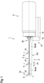
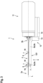
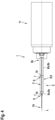
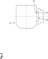
- the Fig. 1 - 6 each show a schematic diagram of a device 1 according to a first exemplary embodiment.
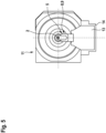
- the device 1 is in the Fig. 1 - 4 in a side view, in Fig. 5 in a front view and in Fig. 6 in a rear view.
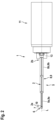
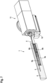
- Fig. 7 shows a schematic diagram of a device 1 according to a further exemplary embodiment in an operating state in a perspective view.
- the device 1 is set up to form one or more bores 3 in a workpiece 4 (cf. Fig. 7 ).
- holes 3 can be formed in drilling positions that are difficult to access, ie in places or positions that are difficult or impossible to reach with a milling tool.
- the device 1 can be used to form elongated bores 3, ie bores 3 with large length dimensions, ie, for example, length dimensions above 10 mm, in elongated workpieces 4, ie in workpieces 4 with large length dimensions, ie, for example, length dimensions above 50 mm.
- the drilling depth or length dimension of the device 1 Holes 3 that can be formed can be significantly above the diameter dimension of the holes 3.
- the holes 3 that can be formed with the device 1 can therefore be deep holes.
- the device 1 can be designed to form bores 3 in a hollow cylindrical workpiece 4 that are centric or non-centric with respect to a symmetry or central axis of a rotationally symmetrical workpiece 4 (cf. Fig. 7 ).
- a workpiece 4, in which corresponding bores 3 can be formed with the device 1, can therefore be a workpiece 4 that is hollow cylindrical and therefore rotationally symmetrical (cf. Fig. 7 ).
- the workpiece 4 can therefore z. B. be tubular or -shaped.
- the device 1 can also be used to form holes 3 in other workpiece designs or geometries.
- the device 1 is not limited to the formation of holes 3 in the area of the inside diameter of a workpiece 4; the device 1 can also be used to form holes 3 in the area of the outside diameter of a workpiece 4.
- the workpiece 4 is made of a machinable material, i.e. H. typically a metal, such as B. steel.
- the device 1 includes a drilling tool 2.
- the drilling tool 2 can be, for example. B. be a deep hole drill or a single lip drill; Other designs of the drilling tool 2 are conceivable.
- the drilling tool 2 comprises a drive-side end 2b and, opposite this, an end 2a having at least one drilling cutting edge (not shown).
- the drilling tool 2 is therefore provided at one end with a drive interface for force or torque-transmitting coupling with a drive device (not shown), which generates a driving force or a drive torque, and at the other end with at least one drilling cutting edge.
- the device 1 further comprises a support device 5 that can be assigned or assigned to the drilling tool 2.
- the support device 5 is to support the Drilling tool 2 is set up on several support areas 6 formed by the support device 5. Based on Fig. 1 , 2 It can be seen that the support areas 6 are arranged along the longitudinal axis L of the drilling tool 2.
- the support device 5 is therefore set up to support the drilling tool 2 via a plurality of support areas 6 arranged along the longitudinal axis L of the drilling tool 2 and thus to support the length of the drilling tool 2.
- the support device 5 comprises a plurality of support elements 7, each of which forms at least one corresponding support area 6.
- the support device 5 or the device 1 is, in particular detachable (without damage or destruction), attached to a processing head 11 that can be assigned or assigned to the drilling tool 2.
- the support device 5 comprises a fastening body 12 arranged or formed on the base body 8, in particular on the second base body element 8b, which has a fastening element 13, in particular (damage-proof or non-destructive) detachable, can be attached to a corresponding fastening element 14 of the processing head 11.
- the attachment of the fastening body 12 to the processing head 11 is realized in the exemplary embodiments shown in the figures, for example, by the positive interaction of the fastening element 13 on the fastening body side and a corresponding fastening element 14 on the processing head side.
- the fastening elements 13, 14, which interact in a form-fitting manner, are secured by a form-fitting element on the part of the fastening body 12, ie a dovetail-like or -shaped fastening section, and a corresponding form-fitting element of the processing head 11, ie a corresponding receptacle for the dovetail-like or -shaped fastening section, trained (cf. Fig. 6 ).
- the processing head 11 is typically equipped with a drive device (not shown) that can be coupled to the drive end of the drilling tool 2, in particular a motor.
- the Machining head 11 therefore typically includes a force transmission element (not designated) which can be coupled to the drilling tool 2 and via which a driving force which can be generated or generated by a corresponding drive device can be transmitted to the drilling tool 2.
- the support device 5 comprises an elongated base body 8 comprising two base body elements 8a, 8b. Although only two base body elements 8a, 8b are shown in the figures, the base body 8 could also include more than two base body elements 8a, 8b.
- a first base body element 8a is mounted movably relative to a second base body element 8b for changing the length dimension of the base body 8.
- the possibility of changing the length dimension of the base body 8, given by the movable mounting of the first base body element 8a relative to the second base body element 8b, allows an individual adjustment of the length of the support device 5 and thus also an individual adjustment of the length of the area in which the support device 5 Support areas 6 can be formed to support the drilling tool 2.
- Movement of the movably mounted first base body element 8a relative to the second base body element 8b, indicated by the arrow P1, includes or represents a translational movement component, ie a movement component along a translation axis.
- the translation axis extends parallel to the longitudinal axis L of the drilling tool 2.
- the movement of the movably mounted first 8a base body element relative to the second base body element 8b can be a driving or a sliding movement.
- the multi-part design of the base body 8 and the associated possibility of moving the first base body element 8a relative to the second base body element 8b provides a (length) variable support option for the drilling tool 2 for a variety of different drilling applications, that is, in particular for a variety of im With regard to their positioning or length dimensions, different bores 3 and/or workpieces 4 given. Due to the ability to support the drilling tool 2 as required and individually (length) variable by the support device 5, a stable support or storage of the drilling tool 2 and thus an exact formation of corresponding bores 3 can be guaranteed, as the drilling tool 2 between its drive end 2b and its at least one end 2a having a corresponding drill cutting edge does not have to “overcome” a long unsupported free length.
- At least one support element 7 forming a support region 6 for the drilling tool 2 is arranged or formed on the base body elements 8a, 8b.
- the base body elements 8a, 8b are therefore each equipped with at least one corresponding support element 7.
- a base body element 8a, 8b is not equipped with a corresponding support element 7.
- the supporting effect that can be achieved by means of the supporting device 5 can therefore be specifically adjusted by the number and arrangement of the respective supporting elements 7.
- respective support elements 7 are formed, for example, by a closed receiving opening 10 for the drilling tool 2 or respective support elements 7 each include a corresponding receiving opening 10.
- the dimensions of the respective receiving openings 10, i.e. H. in particular their cross-sectional geometry, are dependent on the dimensions of the drilling tool 2, i.e. H. in particular its cross-sectional geometry, adapted so that the drilling tool 2 can be stably supported.
- the respective receiving openings 10 passes through the receiving openings 10.
- the first base body element 8a is movable relative to the second base body element 8b between a first and a second position, which positions each correlate with certain length dimensions of the base body 8.
- the first base body element 8a is therefore intermediate relative to the second base body element 8b one in Fig. 1 , 3 shown first position, ie an extended position, which correlates with a first length dimension of the base body 8, and an in Fig. 2 , 4 shown position, ie a retracted position, which correlates with a different, ie shortened, length dimension of the base body 8 from the first length dimension of the base body 8, movably mounted.
- the first base body element 8a can also be movable into intermediate positions lying between the first and second positions.
- the first base body element 8a can therefore optionally be infinitely movable between the first and the second position.
- the base body 8 is designed to be extendable in a telescopic manner, for example.
- the base body 8 therefore comprises a telescope arrangement 9 comprising two telescopic elements 9a, 9b.
- the first base body element 8a forms the first telescopic element 9a and the second base body element 8b forms a second telescopic element 9b which is mounted in a telescopically movable manner relative to the first telescope element 9a.
- respective support elements 7 (without damage or destruction) releasably on respective base body elements 8a, 8b, which opens up further degrees of freedom with regard to an individually adaptable support effect.
- the detachable arrangement or design of the support elements 7 on the base body elements 8a, 8b can z. B. can be realized by the positive and / or non-positive interaction of fastening elements on the support element side (not shown) and, in particular, corresponding fastening elements on the base body element side (not shown).
- Appropriate fasteners can e.g. B. be formed by locking or screw fastening elements or include such.
- fastening options other than positive and/or non-positive, i.e. H. e.g. B. magnetic fastening options are conceivable.
- the base body 8 can - as can be seen from the in Fig. 7 shown embodiment results - at least in sections, if necessary completely, as a hollow profile. Accordingly, they can also Base body elements 8a, 8b can be designed at least in sections, if necessary completely, as a hollow profile.
- the base body 8 or respective base body elements 8a, 8b can therefore have an inner volume in which one or more functional components of the support device 5 can be arranged or formed.
- the design of the base body 8 or the base body elements 8a, 8b as a hollow profile is expedient for the telescopically extendable embodiment of the base body 8.
- a telescopic arrangement 8 comprising two telescopic elements 9a, 9b which are movable relative to one another can be arranged or designed accordingly.
- the possibility that the base body 8 forms part of a telescope arrangement 9 comprising several telescopic elements 9a, 9b can therefore be realized in such a way that respective telescopic elements 9a, 9b are arranged or formed within the hollow profile.
- a first telescopic element 9a can be coupled to the first base body element 8a and the second telescopic element 9b can be coupled to the second base body element 8b.
- the coupling of respective base body elements 8a, 8b and respective telescopic elements 9a, 9b can z. B. can be realized by the positive and/or non-positive and/or cohesive interaction of coupling elements on the base body element side (not shown) and, in particular, corresponding, telescopic element-side coupling elements (not shown).
- Corresponding coupling elements can e.g. B. be formed by locking or screw fastening elements or include such.
- coupling options other than positive and/or non-positive, ie magnetic coupling options are also conceivable.
- the device 1 can include a clamping device (not shown) that can be assigned to the base body 8 and is set up to generate a clamping force that moves the movably mounted first base body element 8a relative to the second base body element 8b.
- the tension force can act in such a way that the first Base body element 8a is always moved in the distal direction, ie typically always in the direction of the (front) end 2a of the drilling tool 2 provided with respective cutting elements, which ensures reliable support of the drilling tool 2 along its longitudinal axis L.
- the clamping device can z. B. be formed by a correspondingly preloaded spring or include one.
- the device 1 can also be assigned a, in particular motor, drive device (not shown), which is set up to generate a force that moves the movably mounted first base body element 8a relative to the second base body element 8b. Movements of the base body elements 8a, 8b could therefore also be controlled by a motor drive.
- a motor drive device not shown
- the stop element can - as in Fig. 7 shown - in operation of the device 1 on a, e.g. B. formed by a counter-stop surface, counter-stop element of the workpiece 4 and thus ensure stable support of the base body 8, which can have a positive effect on the support of the drilling tool 2.
- Example shown of a hollow cylindrical workpiece 4 can be a corresponding counter-stop element z. B. be formed by a radial step formed in the inner volume of the workpiece 4.
- the device 1 can be used in a machining center (not shown) for machining a workpiece 4.
- the machining center includes at least one machining head 11.
- the Support device 5 or device 1 is typically attached to the processing head 11, in particular in a detachable manner (without damage or destruction).
- the processing head 11 is typically in at least one translational and / or rotational degree of freedom of movement at a z.
- B. flange-like bearing device (not shown) of the machining center is movably mounted.
- the machining center can include a magazine for tools, ie in particular for drilling tools 2, in which tools, ie in particular for drilling tools 2, can be stored.
- the introduction and/or removal of tools from a corresponding magazine can, e.g. B. by means of a suitable handling device, such as. B. a handling robot, done automatically.
- a method for forming a hole 3 in a workpiece 4 can be implemented. According to the method, the device 1 is put into operation to form a bore 3 in the workpiece 4.
Landscapes
- Engineering & Computer Science (AREA)
- Mechanical Engineering (AREA)
- Drilling And Boring (AREA)
- Processing Of Stones Or Stones Resemblance Materials (AREA)
Priority Applications (1)
| Application Number | Priority Date | Filing Date | Title |
|---|---|---|---|
| EP23183292.4A EP4241908A3 (fr) | 2018-07-30 | 2018-07-30 | Dispositif de formage d'un alésage dans une pièce à usiner |
Applications Claiming Priority (2)
| Application Number | Priority Date | Filing Date | Title |
|---|---|---|---|
| EP23183292.4A EP4241908A3 (fr) | 2018-07-30 | 2018-07-30 | Dispositif de formage d'un alésage dans une pièce à usiner |
| EP18186394.5A EP3603859B1 (fr) | 2018-07-30 | 2018-07-30 | Dispositif de formage d'un alésage dans une pièce à usiner |
Related Parent Applications (1)
| Application Number | Title | Priority Date | Filing Date |
|---|---|---|---|
| EP18186394.5A Division EP3603859B1 (fr) | 2018-07-30 | 2018-07-30 | Dispositif de formage d'un alésage dans une pièce à usiner |
Publications (2)
| Publication Number | Publication Date |
|---|---|
| EP4241908A2 true EP4241908A2 (fr) | 2023-09-13 |
| EP4241908A3 EP4241908A3 (fr) | 2023-11-01 |
Family
ID=63108429
Family Applications (2)
| Application Number | Title | Priority Date | Filing Date |
|---|---|---|---|
| EP23183292.4A Pending EP4241908A3 (fr) | 2018-07-30 | 2018-07-30 | Dispositif de formage d'un alésage dans une pièce à usiner |
| EP18186394.5A Active EP3603859B1 (fr) | 2018-07-30 | 2018-07-30 | Dispositif de formage d'un alésage dans une pièce à usiner |
Family Applications After (1)
| Application Number | Title | Priority Date | Filing Date |
|---|---|---|---|
| EP18186394.5A Active EP3603859B1 (fr) | 2018-07-30 | 2018-07-30 | Dispositif de formage d'un alésage dans une pièce à usiner |
Country Status (9)
| Country | Link |
|---|---|
| US (1) | US11766725B2 (fr) |
| EP (2) | EP4241908A3 (fr) |
| JP (1) | JP7296149B2 (fr) |
| KR (1) | KR102571675B1 (fr) |
| CN (1) | CN112638566A (fr) |
| EA (1) | EA202190161A1 (fr) |
| ES (1) | ES2958609T3 (fr) |
| PL (1) | PL3603859T3 (fr) |
| WO (1) | WO2020025255A1 (fr) |
Family Cites Families (22)
| Publication number | Priority date | Publication date | Assignee | Title |
|---|---|---|---|---|
| US1831813A (en) * | 1928-07-02 | 1931-11-17 | Independent Pneumatic Tool Co | Attachment for drills |
| US2360942A (en) * | 1943-01-23 | 1944-10-24 | Jack I Ellerstein | Drill guide |
| US2335614A (en) * | 1943-02-25 | 1943-11-30 | Louis A Spievak | Drill guide |
| US2454372A (en) * | 1946-06-06 | 1948-11-23 | Billeter Henry Robert | Drill and drill jig bushing carrier attachment |
| US2674906A (en) * | 1950-08-31 | 1954-04-13 | Robert F Krainz | Hole spacing attachment for drill presses |
| US2612793A (en) * | 1950-11-17 | 1952-10-07 | Robert F Krainz | Hole spacing and centering device |
| US2994235A (en) * | 1957-07-22 | 1961-08-01 | Analytical Engineers Inc | Drill attachment |
| US3397600A (en) * | 1966-03-18 | 1968-08-20 | Mcdonnell Aircraft Corp | Bushing adapter for drill units |
| US3635108A (en) * | 1970-03-09 | 1972-01-18 | Us Navy | Laser-guided boring tool for deep hole boring |
| DE2548100A1 (de) | 1975-10-28 | 1977-05-12 | Bosch Gmbh Robert | Anbauvorrichtung zum absaugen von bohrklein |
| JPH0166914U (fr) | 1987-10-26 | 1989-04-28 | ||
| US5071293A (en) * | 1989-10-30 | 1991-12-10 | Mcdonnell Douglas Corporation | Feed rate regulator for a hand-held drill |
| FR2705270B1 (fr) * | 1993-05-19 | 1995-08-18 | Grandclement Jean Claude | Machine pour percer de longues pièces de bois. |
| JP3442969B2 (ja) * | 1997-07-09 | 2003-09-02 | 日東工器株式会社 | 孔明け加工機 |
| DE10311079A1 (de) | 2003-03-13 | 2004-09-30 | Powers Fasteners Europe Bv | Bohrvorrichtung |
| DE102005043399B4 (de) * | 2005-09-08 | 2009-06-10 | Tixbo Tiefbohr-Center Gmbh & Co.Kg | Vorrichtung zur spanenden Bearbeitung mit automatischem Werkzeugwechsel sowie Verfahren zum automatischen Wechseln von Werkzeugen an der Vorrichtung zur spanenden Bearbeitung |
| DE202010004788U1 (de) * | 2010-01-13 | 2010-08-12 | Auerbach Maschinenfabrik Gmbh | Adaptereinrichtung für Tieflochbohrer sowie Fräsbearbeitungszentrum zur Komplettbearbeitung von Werkstücken mit einer solchen Adaptereinrichtung |
| CN102139386B (zh) * | 2011-03-23 | 2012-08-29 | 桂林机床股份有限公司 | 模块化长距离组孔镗削法 |
| DE102013207815A1 (de) * | 2013-04-29 | 2014-10-30 | Robert Bosch Gmbh | Hilfsvorrichtung zum lotrechten Ausrichten eines Einsatzwerkzeugs |
| CN103658737A (zh) * | 2013-12-10 | 2014-03-26 | 西北稀有金属材料研究院 | 一种金属铍单刃外排屑深孔加工装置及加工方法 |
| CN104439386A (zh) * | 2014-11-18 | 2015-03-25 | 山西北方机械制造有限责任公司 | 一种小直径斜长孔的加工装置 |
| CN108057913A (zh) * | 2018-01-15 | 2018-05-22 | 深圳中科创新精密科技有限公司 | 机械深孔钻 |
-
2018
- 2018-07-30 ES ES18186394T patent/ES2958609T3/es active Active
- 2018-07-30 PL PL18186394.5T patent/PL3603859T3/pl unknown
- 2018-07-30 EP EP23183292.4A patent/EP4241908A3/fr active Pending
- 2018-07-30 EP EP18186394.5A patent/EP3603859B1/fr active Active
-
2019
- 2019-07-08 KR KR1020217005905A patent/KR102571675B1/ko active Active
- 2019-07-08 JP JP2021504296A patent/JP7296149B2/ja active Active
- 2019-07-08 EA EA202190161A patent/EA202190161A1/ru unknown
- 2019-07-08 WO PCT/EP2019/068230 patent/WO2020025255A1/fr not_active Ceased
- 2019-07-08 US US17/264,564 patent/US11766725B2/en active Active
- 2019-07-08 CN CN201980051267.4A patent/CN112638566A/zh active Pending
Also Published As
| Publication number | Publication date |
|---|---|
| EP3603859B1 (fr) | 2023-07-05 |
| EP3603859A1 (fr) | 2020-02-05 |
| US11766725B2 (en) | 2023-09-26 |
| KR102571675B1 (ko) | 2023-08-28 |
| EP4241908A3 (fr) | 2023-11-01 |
| US20210323079A1 (en) | 2021-10-21 |
| WO2020025255A1 (fr) | 2020-02-06 |
| PL3603859T3 (pl) | 2024-04-08 |
| ES2958609T3 (es) | 2024-02-12 |
| EA202190161A1 (ru) | 2021-05-19 |
| JP2021531988A (ja) | 2021-11-25 |
| CN112638566A (zh) | 2021-04-09 |
| JP7296149B2 (ja) | 2023-06-22 |
| KR20210032522A (ko) | 2021-03-24 |
Similar Documents
| Publication | Publication Date | Title |
|---|---|---|
| DE19830903B4 (de) | Einrichtung sowie Verfahren zur Bearbeitung von Bohrungen in einem Werkstück unter Verwendung einer solchen Einrichtung | |
| EP2950955B1 (fr) | Porte-outil pour un outil pourvu d'une tige à filetage extérieur | |
| DE4009940C2 (de) | Einrichtung zur spanabhebenden Bearbeitung von Werkstücken | |
| DE69714781T2 (de) | Hydromechanisches futter | |
| EP2835197A1 (fr) | Mandrin | |
| EP1092494B1 (fr) | Dispositif et procédé de forage pour produire des percages en particulier dans des éléments se chevauchant | |
| EP1997582B1 (fr) | Procédé de calibration d'une table de support de pièce | |
| DE4032694C2 (de) | Spannfutter | |
| DE102013210332B4 (de) | Zerspanungswerkzeug, insbesondere Bohrstange sowie Verfahren zur Bearbeitung einer Anzahl von Bohrungen | |
| EP3603859B1 (fr) | Dispositif de formage d'un alésage dans une pièce à usiner | |
| DE102012104392A1 (de) | Werkzeughalter für ein Werkzeug zum Entgraten und Anfasen | |
| EP3165310A1 (fr) | Dispositif de serrage | |
| EP2177296A1 (fr) | Dispositif de serrage extensible | |
| DE112012002207B4 (de) | Tragbare Werkzeugvorrichtung zum Bearbeiten eines unteren Abschnitts eines Fahrwerkgehäuses eines Luftfahrzeugs sowie Verfahren zu ihrer Anwendung | |
| DE102009023519A1 (de) | Werkzeugmaschine | |
| EP3292932B1 (fr) | Ensemble à ressort permettant de générer la force de serrage d'un dispositif de serrage et dispositif de serrage pourvu d'un tel ensemble à ressort | |
| EP1878550A1 (fr) | Unité de broche pour une unité de perçage à plusieurs broches | |
| EP3890911B1 (fr) | Tête de perçage pour le tournage de trous borgnes | |
| DE2750806A1 (de) | Bohrvorrichtung zum bohren der loecher bei zu verduebelnden werkstuecken | |
| DE19532462A1 (de) | Werkzeug | |
| DE102024105317B3 (de) | Spannvorrichtung | |
| DE102016107244B4 (de) | Hydraulische Dehnspanneinrichtung | |
| DE3417450A1 (de) | Werkzeuganordnung | |
| DE102008046584B3 (de) | Werkzeughalter für ein Werkzeug zur spanenden Bearbeitung eines Werkstücks | |
| DE20217499U1 (de) | Mehrspindel-Bohraggregat mit einer Einrichtung zum Festsetzen der Spindeln |
Legal Events
| Date | Code | Title | Description |
|---|---|---|---|
| PUAI | Public reference made under article 153(3) epc to a published international application that has entered the european phase |
Free format text: ORIGINAL CODE: 0009012 |
|
| STAA | Information on the status of an ep patent application or granted ep patent |
Free format text: STATUS: THE APPLICATION HAS BEEN PUBLISHED |
|
| AC | Divisional application: reference to earlier application |
Ref document number: 3603859 Country of ref document: EP Kind code of ref document: P |
|
| AK | Designated contracting states |
Kind code of ref document: A2 Designated state(s): AL AT BE BG CH CY CZ DE DK EE ES FI FR GB GR HR HU IE IS IT LI LT LU LV MC MK MT NL NO PL PT RO RS SE SI SK SM TR |
|
| REG | Reference to a national code |
Ref country code: DE Ref legal event code: R079 Free format text: PREVIOUS MAIN CLASS: B23B0047320000 Ipc: B23B0049020000 |
|
| PUAL | Search report despatched |
Free format text: ORIGINAL CODE: 0009013 |
|
| AK | Designated contracting states |
Kind code of ref document: A3 Designated state(s): AL AT BE BG CH CY CZ DE DK EE ES FI FR GB GR HR HU IE IS IT LI LT LU LV MC MK MT NL NO PL PT RO RS SE SI SK SM TR |
|
| RIC1 | Information provided on ipc code assigned before grant |
Ipc: B23B 41/02 20060101ALN20230928BHEP Ipc: B23B 47/32 20060101ALI20230928BHEP Ipc: B23B 49/02 20060101AFI20230928BHEP |
|
| STAA | Information on the status of an ep patent application or granted ep patent |
Free format text: STATUS: REQUEST FOR EXAMINATION WAS MADE |
|
| 17P | Request for examination filed |
Effective date: 20240425 |
|
| RBV | Designated contracting states (corrected) |
Designated state(s): AL AT BE BG CH CY CZ DE DK EE ES FI FR GB GR HR HU IE IS IT LI LT LU LV MC MK MT NL NO PL PT RO RS SE SI SK SM TR |