EP4241908A2 - Device for the establishment of a drill hole in a work piece - Google Patents
Device for the establishment of a drill hole in a work piece Download PDFInfo
- Publication number
- EP4241908A2 EP4241908A2 EP23183292.4A EP23183292A EP4241908A2 EP 4241908 A2 EP4241908 A2 EP 4241908A2 EP 23183292 A EP23183292 A EP 23183292A EP 4241908 A2 EP4241908 A2 EP 4241908A2
- Authority
- EP
- European Patent Office
- Prior art keywords
- base body
- support
- drilling tool
- telescopic
- body element
- Prior art date
- Legal status (The legal status is an assumption and is not a legal conclusion. Google has not performed a legal analysis and makes no representation as to the accuracy of the status listed.)
- Pending
Links
- 238000005553 drilling Methods 0.000 claims abstract description 97
- 238000000034 method Methods 0.000 claims description 6
- 230000033001 locomotion Effects 0.000 description 19
- 230000008878 coupling Effects 0.000 description 15
- 238000010168 coupling process Methods 0.000 description 15
- 238000005859 coupling reaction Methods 0.000 description 15
- 230000006378 damage Effects 0.000 description 14
- 230000008093 supporting effect Effects 0.000 description 9
- 238000003754 machining Methods 0.000 description 7
- 230000015572 biosynthetic process Effects 0.000 description 6
- 230000003993 interaction Effects 0.000 description 6
- 238000010586 diagram Methods 0.000 description 3
- 238000003801 milling Methods 0.000 description 3
- 229910000831 Steel Inorganic materials 0.000 description 2
- 230000005540 biological transmission Effects 0.000 description 2
- 230000001419 dependent effect Effects 0.000 description 2
- 230000000694 effects Effects 0.000 description 2
- 239000000463 material Substances 0.000 description 2
- 239000002184 metal Substances 0.000 description 2
- 230000008092 positive effect Effects 0.000 description 2
- 239000010959 steel Substances 0.000 description 2
- 230000001066 destructive effect Effects 0.000 description 1
Images
Classifications
-
- B—PERFORMING OPERATIONS; TRANSPORTING
- B23—MACHINE TOOLS; METAL-WORKING NOT OTHERWISE PROVIDED FOR
- B23B—TURNING; BORING
- B23B49/00—Measuring or gauging equipment on boring machines for positioning or guiding the drill; Devices for indicating failure of drills during boring; Centering devices for holes to be bored
- B23B49/02—Boring templates or bushings
-
- B—PERFORMING OPERATIONS; TRANSPORTING
- B23—MACHINE TOOLS; METAL-WORKING NOT OTHERWISE PROVIDED FOR
- B23B—TURNING; BORING
- B23B47/00—Constructional features of components specially designed for boring or drilling machines; Accessories therefor
- B23B47/32—Arrangements for preventing the running-out of drills or fracture of drills when getting through
-
- B—PERFORMING OPERATIONS; TRANSPORTING
- B23—MACHINE TOOLS; METAL-WORKING NOT OTHERWISE PROVIDED FOR
- B23B—TURNING; BORING
- B23B41/00—Boring or drilling machines or devices specially adapted for particular work; Accessories specially adapted therefor
- B23B41/02—Boring or drilling machines or devices specially adapted for particular work; Accessories specially adapted therefor for boring deep holes; Trepanning, e.g. of gun or rifle barrels
-
- B—PERFORMING OPERATIONS; TRANSPORTING
- B23—MACHINE TOOLS; METAL-WORKING NOT OTHERWISE PROVIDED FOR
- B23B—TURNING; BORING
- B23B49/00—Measuring or gauging equipment on boring machines for positioning or guiding the drill; Devices for indicating failure of drills during boring; Centering devices for holes to be bored
Definitions
- the invention relates to a device for forming a hole in a workpiece, comprising an elongated drilling tool.
- Corresponding devices are basically known in the field of machining workpieces in a variety of embodiments.
- the main task or function of corresponding devices is the formation of holes in workpieces.
- corresponding devices typically include a drilling tool.
- the drilling tool typically comprises a drive-side end and, opposite this, an end having at least one drilling cutting edge.
- the invention is based on the object of specifying an improved device for forming a hole in a workpiece.
- the device described herein is designed to form one or more holes in a workpiece.
- the device is particularly suitable for forming holes in drilling positions that are difficult to access or in difficult locations accessible places of a workpiece, ie typically in places or positions that are hardly or not accessible with a milling tool.
- the device can be set up in particular for forming elongated bores, ie bores with large length dimensions, ie, for example, length dimensions above 10 mm, in elongated workpieces, ie in workpieces with large length dimensions, ie, for example, length dimensions above 50 mm.
- a hole that can be formed with the device - which can basically be a blind hole or a through hole - can therefore be formed in hard-to-reach places or positions on a workpiece to be provided with a hole.
- places or positions that are difficult to access are, in particular, those places or positions that are hardly or not accessible with a milling tool.
- a hole that can be formed with the device can have an elongated geometry.
- the drilling depth or length dimension of a corresponding hole that can be formed with the device can be significantly above the diameter dimension of the hole.
- a hole that can be formed with the device can therefore be a deep hole.
- holes of any length or depth can be formed with the device.
- the device is particularly designed to be centric or extra-centric with respect to a symmetry or central axis of a z.
- the workpiece can be designed at least in sections, if necessary completely, as a hollow cylindrical or rotationally symmetrical.
- a workpiece in which corresponding bores can be formed with the device can therefore be a workpiece that is designed at least in sections, possibly completely, as a hollow cylindrical and thus rotationally symmetrical workpiece.
- the workpiece can therefore z.
- B. be tubular or -shaped.
- the device can also be used to create holes in other workpiece designs or geometries.
- the device is not limited to the formation of holes in the area of the inside diameter of a workpiece; the device can also be used to form holes in the area of the outside diameter of a workpiece.
- the workpiece is typically made of a machinable material, i.e. H. typically a metal, such as B. steel.
- the device includes a drilling tool.
- the drilling tool can be elongated. Any drilling tool that can be used to form a hole in a workpiece can generally be considered as a corresponding drilling tool.
- the drilling tool can be a deep-hole drill or a single-lip drill; other versions of the drilling tool are conceivable.
- the drilling tool typically comprises a drive-side end and, opposite this, an end having at least one drilling cutting edge.
- the drilling tool is therefore provided at one end with a drive interface for force or torque-transmitting coupling with a drive device, in particular a motor, which generates a driving force or a drive torque, and at the other end with at least one drilling cutting edge.
- the device further comprises a support device that can be assigned or assigned to the drilling tool.
- the support device is set up to support the drilling tool on one or more support areas formed by the support device.
- the support areas can typically be arranged or arranged along the or a longitudinal axis of the drilling tool.
- the support device is therefore set up in particular to support the drilling tool via one or more support areas which can be arranged or are arranged along the or a longitudinal axis of the drilling tool.
- the support device is correspondingly along or along a longitudinal axis of the Drilling tool can be arranged or arranged support areas, in particular for supporting the length of the drilling tool.
- the support device typically comprises one or more support elements, each of which forms at least one corresponding support area.
- the support device comprises an elongated base body comprising at least two base body elements. At least one base body element is mounted movably relative to at least one further base body element for changing the length dimension of the base body.
- the possibility of changing the length dimension of the base body given by the movable mounting of at least one base body element relative to at least one further base body element allows an individual adjustment of the length of the support device and thus also an individual adjustment of the length of the area in which support areas for supporting the Drilling tool can be formed.
- the movement of a movably mounted base body element relative to at least one further, possibly also movably mounted, base body element typically includes a translational movement component, i.e. H. a movement component along a translation axis, or represents such.
- a corresponding translation axis typically extends parallel to the longitudinal axis of the drilling tool.
- the movement of a movably mounted base body element relative to at least one further base body element can be, for example, a driving or a sliding movement.
- the multi-part design of the base body as described and the associated possibility of moving at least one base body element relative to at least one further base body element provide a (length) variable support option for the drilling tool for a variety of different drilling applications, that is, in particular for a variety of applications on their positioning on or in the workpiece and/or their Length dimensions are given for different bores and/or workpieces.
- the support device can ensure stable support or storage or positioning of the drilling tool and thus precise formation of corresponding holes, as the drilling tool can be used even in difficult-to-access drilling positions its drive end and its end having at least one corresponding drill cutting edge does not have to "overcome" a long unsupported free length.
- This provides an improved device for forming a hole in a workpiece.
- Respective base body elements can be movable relative to one another, in particular between first and second positions, which positions each correlate with specific length dimensions of the base body. At least one base body element can therefore be moved relative to at least one further base body element between a first position, i.e. H. e.g. B. an extended position, which correlates with a first length dimension of the base body, and at least one further position, i.e. H. e.g. B. a retracted position, which correlates with a further length dimension of the base body that is different from the first length dimension of the base body, can be movably mounted.
- respective base body elements can also be movable into intermediate positions lying between respective first and second positions.
- Respective base body elements can therefore optionally be infinitely movable between respective first and second positions.
- the base body can be designed to be telescopically extendable.
- the base body can therefore form a telescope arrangement comprising several telescopic elements or a component of one.
- a first base body element can form a first telescopic element or be coupled to one and at least one further base body element form a further telescopic element that is movably mounted in a telescopic manner relative to the first telescopic element or can be coupled to one.
- At least one support element forming a support area for the drilling tool can be arranged or formed on at least one base body element. Therefore, respective base body elements can each be equipped with at least one corresponding support element. Nevertheless, it is also possible that individual base body elements cannot be equipped with a corresponding support element. The supporting effect that can be achieved by means of the supporting device can therefore be specifically adjusted by the number and arrangement of the respective supporting elements.
- at least one support element forming a support region for the drilling tool can be arranged or formed on the or a first base body element and on at least one further base body element.
- a respective support element can z. B. be formed by or include an open or closed receiving opening for the drilling tool.
- the dimensions of a corresponding receiving opening i.e. H.
- their cross-sectional geometry is typically related to the dimensions of the drilling tool, i.e. H. adapted in particular to its cross-sectional geometry, so that the drilling tool can be stably supported.
- the drilling tool can pass through a respective receiving opening at least in sections, if necessary completely.
- the base body can be designed as a hollow profile at least in sections, if necessary completely. Accordingly, respective base body elements can also be designed at least in sections, if necessary completely, as a hollow profile.
- the base body or respective base body elements therefore have an inner volume in which one or more functional components of the support device can be arranged or formed.
- the design of the base body or respective base body elements as a hollow profile is particularly useful for the aforementioned telescopically extendable embodiment of the base body.
- a telescopic arrangement comprising a first telescopic element and at least one further telescopic element mounted in a telescopically movable manner relative to the first telescopic element can be arranged or designed.
- the already mentioned possibility that the base body forms part of a telescope arrangement comprising several telescopic elements can therefore be implemented in such a way that respective telescopic elements are arranged or designed within the hollow profile.
- a first telescopic element can be coupled to a first base body element, ie in particular motion-coupled, and at least one further telescopic element can be coupled to at least one further base body element, ie in particular motion-coupled.
- the coupling or movement coupling of respective base body elements and respective telescopic elements can z. B. can be realized by the positive and/or non-positive and/or cohesive interaction of coupling elements on the base body element side and, in particular, corresponding, telescopic element-side coupling elements.
- Corresponding coupling elements can e.g. B. be formed by locking or screw fastening elements or include such.
- other than positive and/or non-positive coupling options are also possible, i.e. H. e.g. B. magnetic coupling options are conceivable.
- the device can comprise at least one clamping device that can be assigned or assigned to the base body and is set up to generate a clamping force that moves a movably mounted base body element relative to at least one further base body element.
- the clamping force can act in such a way that at least one movably mounted base body element is always in the distal direction, i.e. H. is typically always moved in the direction of the end of the drilling tool provided with respective cutting elements, which ensures reliable support of the drilling tool along its longitudinal axis.
- the clamping device can z. B. be formed by a correspondingly preloaded spring or include one.
- the device can also be assigned or assigned a, in particular motor, drive device, which is set up to generate a force that moves a movably mounted base body element relative to at least one further base body element. Movements of base body elements can therefore also be controlled by a motor drive.
- a motor drive device which is set up to generate a force that moves a movably mounted base body element relative to at least one further base body element. Movements of base body elements can therefore also be controlled by a motor drive.
- the term “clamping device” can therefore also include a corresponding drive device; A corresponding clamping device can therefore optionally also include a corresponding drive device.
- the support device or the device can, in particular, be detachable (without damage or destruction), on a device that can be assigned to the drilling tool or assigned processing head.
- the support device can comprise a fastening body arranged or formed on the base body, in particular on a base body element, which can be detached via a, in particular mechanical, fastening element, in particular (without damage or non-destruction). can be attached or attached to a corresponding fastening element of the processing head.
- the attachment of the fastening body to the processing head can z. B.
- Corresponding positively interacting fastening elements can e.g. B. by a positive locking element on the part of the fastening body, ie B. a dovetail-like or -shaped fastening section, and a corresponding positive locking element of the processing head, ie z B. a corresponding receptacle for the dovetail-like or -shaped fastening section, or include such.
- Corresponding non-positively interacting fastening elements can e.g. B. be formed by screw fastening elements or include such.
- a corresponding processing head is typically equipped with a drive device that can be coupled to the drive end of the drilling tool, in particular a motor drive device.
- a corresponding processing head therefore typically comprises at least one force transmission element that can be coupled or coupled to the drilling tool, via which a driving force that can be generated or generated by a corresponding drive device can be transmitted to the drilling tool.
- the free end of the base body element forming the free end of the base body is provided with a, e.g. B. stop element formed by a stop surface, can be formed or a may include such.
- the stop element can be on one, e.g. B. formed by a counter-stop surface, the counter-stop element of the workpiece rests and thus ensures stable support of the base body, which can have a positive effect on the support of the drilling tool.
- a corresponding counter-stop element can be used, for example.
- B. be formed by a radial step formed in the internal volume of the workpiece.
- the invention also relates to a support device for a device as described.
- the support device is set up to support a drilling tool on at least one support area and comprises an elongated base body comprising at least two base body elements, at least one base body element being movably mounted relative to at least one further base body element for changing the length dimension of the base body. All embodiments in connection with the device apply analogously to the support device.
- the invention further relates to a machining center for machining a workpiece, comprising at least one device as described. All embodiments in connection with the device apply analogously to the machining center.
- the machining center typically includes at least one machining head.
- the support device is typically, in particular releasably (without damage or destruction), attached to a processing head that can be assigned or assigned to the drilling tool or the device.
- the machining head is typically mounted movably in at least one translational and/or rotational degree of freedom of movement on a bearing device of the machining center.
- the machining center can include a magazine for tools, ie in particular for drilling tools, in which tools, ie in particular for drilling tools, can be stored.
- the introduction and/or removal of tools from a corresponding magazine can, e.g. B. by means of a suitable handling device, such as. B. a handling robot, done automatically.
- a suitable handling device such as. B. a handling robot
- the invention relates to a method for forming a hole, for example an elongated blind hole, in a workpiece.
- a device as described for forming the bore is put into operation or used. All embodiments in connection with the device apply analogously to the method.
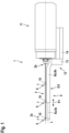
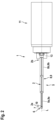
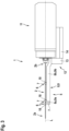
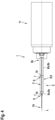
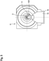
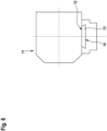
- the Fig. 1 - 6 each show a schematic diagram of a device 1 according to a first exemplary embodiment.
- the device 1 is in the Fig. 1 - 4 in a side view, in Fig. 5 in a front view and in Fig. 6 in a rear view.
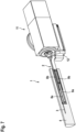
- Fig. 7 shows a schematic diagram of a device 1 according to a further exemplary embodiment in an operating state in a perspective view.
- the device 1 is set up to form one or more bores 3 in a workpiece 4 (cf. Fig. 7 ).
- holes 3 can be formed in drilling positions that are difficult to access, ie in places or positions that are difficult or impossible to reach with a milling tool.
- the device 1 can be used to form elongated bores 3, ie bores 3 with large length dimensions, ie, for example, length dimensions above 10 mm, in elongated workpieces 4, ie in workpieces 4 with large length dimensions, ie, for example, length dimensions above 50 mm.
- the drilling depth or length dimension of the device 1 Holes 3 that can be formed can be significantly above the diameter dimension of the holes 3.
- the holes 3 that can be formed with the device 1 can therefore be deep holes.
- the device 1 can be designed to form bores 3 in a hollow cylindrical workpiece 4 that are centric or non-centric with respect to a symmetry or central axis of a rotationally symmetrical workpiece 4 (cf. Fig. 7 ).
- a workpiece 4, in which corresponding bores 3 can be formed with the device 1, can therefore be a workpiece 4 that is hollow cylindrical and therefore rotationally symmetrical (cf. Fig. 7 ).
- the workpiece 4 can therefore z. B. be tubular or -shaped.
- the device 1 can also be used to form holes 3 in other workpiece designs or geometries.
- the device 1 is not limited to the formation of holes 3 in the area of the inside diameter of a workpiece 4; the device 1 can also be used to form holes 3 in the area of the outside diameter of a workpiece 4.
- the workpiece 4 is made of a machinable material, i.e. H. typically a metal, such as B. steel.
- the device 1 includes a drilling tool 2.
- the drilling tool 2 can be, for example. B. be a deep hole drill or a single lip drill; Other designs of the drilling tool 2 are conceivable.
- the drilling tool 2 comprises a drive-side end 2b and, opposite this, an end 2a having at least one drilling cutting edge (not shown).
- the drilling tool 2 is therefore provided at one end with a drive interface for force or torque-transmitting coupling with a drive device (not shown), which generates a driving force or a drive torque, and at the other end with at least one drilling cutting edge.
- the device 1 further comprises a support device 5 that can be assigned or assigned to the drilling tool 2.
- the support device 5 is to support the Drilling tool 2 is set up on several support areas 6 formed by the support device 5. Based on Fig. 1 , 2 It can be seen that the support areas 6 are arranged along the longitudinal axis L of the drilling tool 2.
- the support device 5 is therefore set up to support the drilling tool 2 via a plurality of support areas 6 arranged along the longitudinal axis L of the drilling tool 2 and thus to support the length of the drilling tool 2.
- the support device 5 comprises a plurality of support elements 7, each of which forms at least one corresponding support area 6.
- the support device 5 or the device 1 is, in particular detachable (without damage or destruction), attached to a processing head 11 that can be assigned or assigned to the drilling tool 2.
- the support device 5 comprises a fastening body 12 arranged or formed on the base body 8, in particular on the second base body element 8b, which has a fastening element 13, in particular (damage-proof or non-destructive) detachable, can be attached to a corresponding fastening element 14 of the processing head 11.
- the attachment of the fastening body 12 to the processing head 11 is realized in the exemplary embodiments shown in the figures, for example, by the positive interaction of the fastening element 13 on the fastening body side and a corresponding fastening element 14 on the processing head side.
- the fastening elements 13, 14, which interact in a form-fitting manner, are secured by a form-fitting element on the part of the fastening body 12, ie a dovetail-like or -shaped fastening section, and a corresponding form-fitting element of the processing head 11, ie a corresponding receptacle for the dovetail-like or -shaped fastening section, trained (cf. Fig. 6 ).
- the processing head 11 is typically equipped with a drive device (not shown) that can be coupled to the drive end of the drilling tool 2, in particular a motor.
- the Machining head 11 therefore typically includes a force transmission element (not designated) which can be coupled to the drilling tool 2 and via which a driving force which can be generated or generated by a corresponding drive device can be transmitted to the drilling tool 2.
- the support device 5 comprises an elongated base body 8 comprising two base body elements 8a, 8b. Although only two base body elements 8a, 8b are shown in the figures, the base body 8 could also include more than two base body elements 8a, 8b.
- a first base body element 8a is mounted movably relative to a second base body element 8b for changing the length dimension of the base body 8.
- the possibility of changing the length dimension of the base body 8, given by the movable mounting of the first base body element 8a relative to the second base body element 8b, allows an individual adjustment of the length of the support device 5 and thus also an individual adjustment of the length of the area in which the support device 5 Support areas 6 can be formed to support the drilling tool 2.
- Movement of the movably mounted first base body element 8a relative to the second base body element 8b, indicated by the arrow P1, includes or represents a translational movement component, ie a movement component along a translation axis.
- the translation axis extends parallel to the longitudinal axis L of the drilling tool 2.
- the movement of the movably mounted first 8a base body element relative to the second base body element 8b can be a driving or a sliding movement.
- the multi-part design of the base body 8 and the associated possibility of moving the first base body element 8a relative to the second base body element 8b provides a (length) variable support option for the drilling tool 2 for a variety of different drilling applications, that is, in particular for a variety of im With regard to their positioning or length dimensions, different bores 3 and/or workpieces 4 given. Due to the ability to support the drilling tool 2 as required and individually (length) variable by the support device 5, a stable support or storage of the drilling tool 2 and thus an exact formation of corresponding bores 3 can be guaranteed, as the drilling tool 2 between its drive end 2b and its at least one end 2a having a corresponding drill cutting edge does not have to “overcome” a long unsupported free length.
- At least one support element 7 forming a support region 6 for the drilling tool 2 is arranged or formed on the base body elements 8a, 8b.
- the base body elements 8a, 8b are therefore each equipped with at least one corresponding support element 7.
- a base body element 8a, 8b is not equipped with a corresponding support element 7.
- the supporting effect that can be achieved by means of the supporting device 5 can therefore be specifically adjusted by the number and arrangement of the respective supporting elements 7.
- respective support elements 7 are formed, for example, by a closed receiving opening 10 for the drilling tool 2 or respective support elements 7 each include a corresponding receiving opening 10.
- the dimensions of the respective receiving openings 10, i.e. H. in particular their cross-sectional geometry, are dependent on the dimensions of the drilling tool 2, i.e. H. in particular its cross-sectional geometry, adapted so that the drilling tool 2 can be stably supported.
- the respective receiving openings 10 passes through the receiving openings 10.
- the first base body element 8a is movable relative to the second base body element 8b between a first and a second position, which positions each correlate with certain length dimensions of the base body 8.
- the first base body element 8a is therefore intermediate relative to the second base body element 8b one in Fig. 1 , 3 shown first position, ie an extended position, which correlates with a first length dimension of the base body 8, and an in Fig. 2 , 4 shown position, ie a retracted position, which correlates with a different, ie shortened, length dimension of the base body 8 from the first length dimension of the base body 8, movably mounted.
- the first base body element 8a can also be movable into intermediate positions lying between the first and second positions.
- the first base body element 8a can therefore optionally be infinitely movable between the first and the second position.
- the base body 8 is designed to be extendable in a telescopic manner, for example.
- the base body 8 therefore comprises a telescope arrangement 9 comprising two telescopic elements 9a, 9b.
- the first base body element 8a forms the first telescopic element 9a and the second base body element 8b forms a second telescopic element 9b which is mounted in a telescopically movable manner relative to the first telescope element 9a.
- respective support elements 7 (without damage or destruction) releasably on respective base body elements 8a, 8b, which opens up further degrees of freedom with regard to an individually adaptable support effect.
- the detachable arrangement or design of the support elements 7 on the base body elements 8a, 8b can z. B. can be realized by the positive and / or non-positive interaction of fastening elements on the support element side (not shown) and, in particular, corresponding fastening elements on the base body element side (not shown).
- Appropriate fasteners can e.g. B. be formed by locking or screw fastening elements or include such.
- fastening options other than positive and/or non-positive, i.e. H. e.g. B. magnetic fastening options are conceivable.
- the base body 8 can - as can be seen from the in Fig. 7 shown embodiment results - at least in sections, if necessary completely, as a hollow profile. Accordingly, they can also Base body elements 8a, 8b can be designed at least in sections, if necessary completely, as a hollow profile.
- the base body 8 or respective base body elements 8a, 8b can therefore have an inner volume in which one or more functional components of the support device 5 can be arranged or formed.
- the design of the base body 8 or the base body elements 8a, 8b as a hollow profile is expedient for the telescopically extendable embodiment of the base body 8.
- a telescopic arrangement 8 comprising two telescopic elements 9a, 9b which are movable relative to one another can be arranged or designed accordingly.
- the possibility that the base body 8 forms part of a telescope arrangement 9 comprising several telescopic elements 9a, 9b can therefore be realized in such a way that respective telescopic elements 9a, 9b are arranged or formed within the hollow profile.
- a first telescopic element 9a can be coupled to the first base body element 8a and the second telescopic element 9b can be coupled to the second base body element 8b.
- the coupling of respective base body elements 8a, 8b and respective telescopic elements 9a, 9b can z. B. can be realized by the positive and/or non-positive and/or cohesive interaction of coupling elements on the base body element side (not shown) and, in particular, corresponding, telescopic element-side coupling elements (not shown).
- Corresponding coupling elements can e.g. B. be formed by locking or screw fastening elements or include such.
- coupling options other than positive and/or non-positive, ie magnetic coupling options are also conceivable.
- the device 1 can include a clamping device (not shown) that can be assigned to the base body 8 and is set up to generate a clamping force that moves the movably mounted first base body element 8a relative to the second base body element 8b.
- the tension force can act in such a way that the first Base body element 8a is always moved in the distal direction, ie typically always in the direction of the (front) end 2a of the drilling tool 2 provided with respective cutting elements, which ensures reliable support of the drilling tool 2 along its longitudinal axis L.
- the clamping device can z. B. be formed by a correspondingly preloaded spring or include one.
- the device 1 can also be assigned a, in particular motor, drive device (not shown), which is set up to generate a force that moves the movably mounted first base body element 8a relative to the second base body element 8b. Movements of the base body elements 8a, 8b could therefore also be controlled by a motor drive.
- a motor drive device not shown
- the stop element can - as in Fig. 7 shown - in operation of the device 1 on a, e.g. B. formed by a counter-stop surface, counter-stop element of the workpiece 4 and thus ensure stable support of the base body 8, which can have a positive effect on the support of the drilling tool 2.
- Example shown of a hollow cylindrical workpiece 4 can be a corresponding counter-stop element z. B. be formed by a radial step formed in the inner volume of the workpiece 4.
- the device 1 can be used in a machining center (not shown) for machining a workpiece 4.
- the machining center includes at least one machining head 11.
- the Support device 5 or device 1 is typically attached to the processing head 11, in particular in a detachable manner (without damage or destruction).
- the processing head 11 is typically in at least one translational and / or rotational degree of freedom of movement at a z.
- B. flange-like bearing device (not shown) of the machining center is movably mounted.
- the machining center can include a magazine for tools, ie in particular for drilling tools 2, in which tools, ie in particular for drilling tools 2, can be stored.
- the introduction and/or removal of tools from a corresponding magazine can, e.g. B. by means of a suitable handling device, such as. B. a handling robot, done automatically.
- a method for forming a hole 3 in a workpiece 4 can be implemented. According to the method, the device 1 is put into operation to form a bore 3 in the workpiece 4.
Landscapes
- Engineering & Computer Science (AREA)
- Mechanical Engineering (AREA)
- Drilling And Boring (AREA)
- Processing Of Stones Or Stones Resemblance Materials (AREA)
Abstract
Vorrichtung (1) zum Ausbilden einer Bohrung (3) in einem Werkstück (4), umfassendein Bohrwerkzeug (2),eine dem Bohrwerkzeug (2) zuordenbare oder zugeordnete Abstützeinrichtung (5), welche zur Abstützung des Bohrwerkzeugs (2) an wenigstens einem Abstützbereich (6) eingerichtet ist, wobeidie Abstützeinrichtung (5) einen wenigstens zwei Grundkörperelemente (8a, 8b) umfassenden länglichen Grundkörper (8) umfasst, wobei wenigstens ein Grundkörperelement (8a) zur Änderung der Längenabmessung des Grundkörpers (8) relativ zu wenigstens einem weiteren Grundkörperelement (8b) bewegbar gelagert ist.Device (1) for forming a hole (3) in a workpiece (4), comprising a drilling tool (2), a support device (5) which can be assigned or assigned to the drilling tool (2) and which is used to support the drilling tool (2) on at least one support area (6) is set up, wherein the support device (5) comprises an elongated base body (8) comprising at least two base body elements (8a, 8b), at least one base body element (8a) for changing the length dimension of the base body (8) relative to at least one further base body element (8b) is movably mounted.
Description
Die Erfindung betrifft eine Vorrichtung zum Ausbilden einer Bohrung in einem Werkstück, umfassend ein längliches Bohrwerkzeug.The invention relates to a device for forming a hole in a workpiece, comprising an elongated drilling tool.
Entsprechende Vorrichtungen sind aus dem Bereich der spanenden Bearbeitung von Werkstücken in einer Vielzahl an Ausführungsformen dem Grunde nach bekannt. Hauptaufgabe bzw. -funktion entsprechender Vorrichtungen ist die Ausbildung von Bohrungen in Werkstücken.Corresponding devices are basically known in the field of machining workpieces in a variety of embodiments. The main task or function of corresponding devices is the formation of holes in workpieces.
Zur Ausbildung entsprechender Bohrungen umfassen entsprechende Vorrichtungen typischerweise ein Bohrwerkzeug. Das Bohrwerkzeug umfasst typischerweise ein antriebsseitiges Ende und diesem gegenüber liegend ein wenigstens eine Bohrschneide aufweisendes Ende.To form corresponding holes, corresponding devices typically include a drilling tool. The drilling tool typically comprises a drive-side end and, opposite this, an end having at least one drilling cutting edge.
Bei der Ausbildung von schwer zugänglichen Bohrungen in Werkstücken kann eine stabile Lagerung und Positionierung des Bohrwerkzeugs und somit eine exakte Ausbildung einer entsprechenden Bohrung eine Herausforderung darstellen, als das Bohrwerkzeug zwischen seinem antriebsseitigen Ende und seinem wenigstens eine entsprechende Bohrschneide aufweisenden Ende eine ununterstützte freie Länge "überwinden" muss.When forming holes in workpieces that are difficult to access, stable storage and positioning of the drilling tool and thus precise formation of a corresponding hole can pose a challenge as the drilling tool "overcomes" an unsupported free length between its drive end and its end having at least one corresponding drilling cutting edge " must.
Der Erfindung liegt die Aufgabe zugrunde, eine demgegenüber verbesserte Vorrichtung zum Ausbilden einer Bohrung in einem Werkstück anzugeben.The invention is based on the object of specifying an improved device for forming a hole in a workpiece.
Die Aufgabe wird durch eine Vorrichtung gemäß Anspruch 1 gelöst. Die hierzu abhängigen Ansprüche betreffen mögliche Ausführungsformen der Vorrichtung.The task is solved by a device according to claim 1. The dependent claims relate to possible embodiments of the device.
Die hierin beschriebene Vorrichtung ist zum Ausbilden einer oder mehrerer Bohrungen in einem Werkstück eingerichtet. Die Vorrichtung ist insbesondere zum Ausbilden von Bohrungen an schwer zugänglichen Bohrpositionen bzw. an schwer zugänglichen Stellen eines Werkstücks, d. h. typischerweise an Stellen bzw. Positionen, welche mit einem Fräswerkzeug kaum oder nicht zugänglich sind, eingerichtet. Die Vorrichtung kann insbesondere zum Ausbilden länglicher Bohrungen, d. h. von Bohrungen mit großen Längenabmessungen, d. h. z. B. Längenabmessungen oberhalb 10 mm, in länglichen Werkstücken, d. h. in Werkstücken mit großen Längenabmessungen, d. h. z. B. Längenabmessungen oberhalb 50 mm, eingerichtet sein.The device described herein is designed to form one or more holes in a workpiece. The device is particularly suitable for forming holes in drilling positions that are difficult to access or in difficult locations accessible places of a workpiece, ie typically in places or positions that are hardly or not accessible with a milling tool. The device can be set up in particular for forming elongated bores, ie bores with large length dimensions, ie, for example, length dimensions above 10 mm, in elongated workpieces, ie in workpieces with large length dimensions, ie, for example, length dimensions above 50 mm.
Eine mit der Vorrichtung ausbildbare Bohrung - bei welcher es sich grundsätzlich um eine Sackloch- oder um eine Durchgangsbohrung handeln kann - kann sonach an schwer zugänglichen Stellen bzw. Positionen eines mit einer Bohrung zu versehenen Werkstücks ausgebildet werden. Wie erwähnt, handelt es sich bei schwer zugänglichen Stellen bzw. Positionen insbesondere um solche Stellen bzw. Positionen, welche mit einem Fräswerkzeug kaum oder nicht zugänglich sind.A hole that can be formed with the device - which can basically be a blind hole or a through hole - can therefore be formed in hard-to-reach places or positions on a workpiece to be provided with a hole. As mentioned, places or positions that are difficult to access are, in particular, those places or positions that are hardly or not accessible with a milling tool.
Eine mit der Vorrichtung ausbildbare Bohrung kann eine längliche Geometrie aufweisen. Die Bohrtiefen- bzw. Längenabmessung einer entsprechenden mit der Vorrichtung ausbildbaren Bohrung kann deutlich oberhalb der Durchmesserabmessung der Bohrung liegen. Bei einer mit der Vorrichtung ausbildbaren Bohrung kann es sich sonach um eine Tiefbohrung handeln.A hole that can be formed with the device can have an elongated geometry. The drilling depth or length dimension of a corresponding hole that can be formed with the device can be significantly above the diameter dimension of the hole. A hole that can be formed with the device can therefore be a deep hole.
Grundsätzlich sind mit der Vorrichtung Bohrungen jedweder Längenabmessung bzw. Tiefe ausbildbar.In principle, holes of any length or depth can be formed with the device.
Die Vorrichtung ist insbesondere zur Ausbildung zentrisch oder außerzentrisch bezüglich einer Symmetrie- bzw. Zentralachse eines z. B. rotationssymmetrischen Werkstücks liegender Bohrungen ausgebildet. Das Werkstück kann zumindest abschnittsweise, gegebenenfalls vollständig, hohlzylindrisch bzw. rotationssymmetrisch ausgeführt sein. Bei einem Werkstück, in welchem mit der Vorrichtung entsprechende Bohrungen ausbildbar sind, kann es sich sonach um ein zumindest abschnittsweise, gegebenenfalls vollständig, hohlzylindrisch und somit rotationssymmetrisch ausgeführtes Werkstück handeln. Das Werkstück kann sonach z. B. rohrartig bzw. -förmig ausgeführt sein.The device is particularly designed to be centric or extra-centric with respect to a symmetry or central axis of a z. B. rotationally symmetrical workpiece lying holes formed. The workpiece can be designed at least in sections, if necessary completely, as a hollow cylindrical or rotationally symmetrical. A workpiece in which corresponding bores can be formed with the device can therefore be a workpiece that is designed at least in sections, possibly completely, as a hollow cylindrical and thus rotationally symmetrical workpiece. The workpiece can therefore z. B. be tubular or -shaped.
Grundsätzlich sind mit der Vorrichtung auch Bohrungen in anderen Werkstückausführungen bzw. Geometrien ausbildbar. Die Vorrichtung ist nicht auf die Ausbildung von Bohrungen im Bereich des Innendurchmessers eines Werkstücks beschränkt, mit der Vorrichtung lassen sich auch Bohrungen im Bereich des Außendurchmessers eines Werkstücks ausbilden.In principle, the device can also be used to create holes in other workpiece designs or geometries. The device is not limited to the formation of holes in the area of the inside diameter of a workpiece; the device can also be used to form holes in the area of the outside diameter of a workpiece.
Unabhängig von seiner Geometrie ist das Werkstück typischerweise aus einem spanend bearbeitbaren Material, d. h. typischerweise einem Metall, wie z. B. Stahl, gebildet.Regardless of its geometry, the workpiece is typically made of a machinable material, i.e. H. typically a metal, such as B. steel.
Zum Ausbilden entsprechender Bohrungen umfasst die Vorrichtung ein Bohrwerkzeug. Das Bohrwerkzeug kann länglich ausgeführt sein. Als entsprechendes Bohrwerkzeug kommt im Allgemeinen jedwedes Bohrwerkzeug in Betracht, mit welchem eine Bohrung in einem Werkstück ausbildbar ist. Bei dem Bohrwerkzeug kann es sich um einen Tieflochbohrer bzw. um einen Einlippenbohrer handeln; andere Ausführungen des Bohrwerkzeugs sind denkbar. Das Bohrwerkzeug umfasst typischerweise ein antriebsseitiges Ende und diesem gegenüber liegend ein wenigstens eine Bohrschneide aufweisendes Ende. Das Bohrwerkzeug ist damit einends mit einer Antriebsschnittstelle zur kraft- bzw. momentübertragenden Kopplung mit einer eine Antriebskraft bzw. eine Antriebsmoment erzeugenden, insbesondere motorischen, Antriebseinrichtung und andernends mit wenigstens einer Bohrschneide versehen.To form corresponding holes, the device includes a drilling tool. The drilling tool can be elongated. Any drilling tool that can be used to form a hole in a workpiece can generally be considered as a corresponding drilling tool. The drilling tool can be a deep-hole drill or a single-lip drill; other versions of the drilling tool are conceivable. The drilling tool typically comprises a drive-side end and, opposite this, an end having at least one drilling cutting edge. The drilling tool is therefore provided at one end with a drive interface for force or torque-transmitting coupling with a drive device, in particular a motor, which generates a driving force or a drive torque, and at the other end with at least one drilling cutting edge.
Die Vorrichtung umfasst weiterhin eine dem Bohrwerkzeug zuordenbare oder zugeordnete Abstützeinrichtung. Die Abstützeinrichtung ist zur Abstützung des Bohrwerkzeugs an einem oder mehreren durch die Abstützeinrichtung gebildeten Abstützbereichen eingerichtet. Die Abstützbereiche sind typischerweise entlang der bzw. einer Längsachse des Bohrwerkzeugs anordenbar oder angeordnet. Die Abstützeinrichtung ist sonach insbesondere zur Abstützung des Bohrwerkzeugs über einen oder mehrere entlang der bzw. einer Längsachse des Bohrwerkzeugs anordenbare oder angeordnete Abstützbereiche eingerichtet. Entsprechend ist die Abstützeinrichtung über entsprechende entlang der bzw. einer Längsachse des Bohrwerkzeugs anordenbare oder angeordnete Abstützbereiche insbesondere zur Längenabstützung des Bohrwerkzeugs eingerichtet. Wie sich im Weiteren ergibt, umfasst die Abstützeinrichtung typischerweise ein oder mehrere Abstützelemente, welche jeweils wenigstens einen entsprechenden Abstützbereich bilden.The device further comprises a support device that can be assigned or assigned to the drilling tool. The support device is set up to support the drilling tool on one or more support areas formed by the support device. The support areas can typically be arranged or arranged along the or a longitudinal axis of the drilling tool. The support device is therefore set up in particular to support the drilling tool via one or more support areas which can be arranged or are arranged along the or a longitudinal axis of the drilling tool. Accordingly, the support device is correspondingly along or along a longitudinal axis of the Drilling tool can be arranged or arranged support areas, in particular for supporting the length of the drilling tool. As can be seen below, the support device typically comprises one or more support elements, each of which forms at least one corresponding support area.
Die Abstützeinrichtung umfasst einen wenigstens zwei Grundkörperelemente umfassenden länglichen Grundkörper. Dabei ist wenigstens ein Grundkörperelement zur Änderung der Längenabmessung des Grundkörpers relativ zu wenigstens einem weiteren Grundkörperelement bewegbar gelagert. Die durch die bewegbare Lagerung wenigstens eines Grundkörperelements relativ zu wenigstens einem weiteren Grundkörperelement gegebene Möglichkeit der Änderung der Längenabmessung des Grundkörpers erlaubt eine individuelle Anpassung der Länge der Abstützeinrichtung und damit auch eine individuelle Anpassung der Länge des Bereichs, in welchem über die Abstützeinrichtung Abstützbereiche zur Abstützung des Bohrwerkzeugs gebildet werden können.The support device comprises an elongated base body comprising at least two base body elements. At least one base body element is mounted movably relative to at least one further base body element for changing the length dimension of the base body. The possibility of changing the length dimension of the base body given by the movable mounting of at least one base body element relative to at least one further base body element allows an individual adjustment of the length of the support device and thus also an individual adjustment of the length of the area in which support areas for supporting the Drilling tool can be formed.
Die Bewegung eines bewegbar gelagerten Grundkörperelements relativ zu wenigstens einem weiteren, gegebenenfalls ebenso bewegbar gelagerten, Grundkörperelement beinhaltet typischerweise eine translatorische Bewegungskomponente, d. h. eine Bewegungskomponente entlang einer Translationsachse, bzw. stellt eine solche dar. Eine entsprechende Translationsachse erstreckt sich typischerweise parallel zu der Längsachse des Bohrwerkzeugs. Bei der Bewegung eines bewegbar gelagerten Grundkörperelements relativ zu wenigstens einem weiteren Grundkörperelement kann es sich beispielsweise um eine Fahr- oder um eine Schiebebewegung handeln.The movement of a movably mounted base body element relative to at least one further, possibly also movably mounted, base body element typically includes a translational movement component, i.e. H. a movement component along a translation axis, or represents such. A corresponding translation axis typically extends parallel to the longitudinal axis of the drilling tool. The movement of a movably mounted base body element relative to at least one further base body element can be, for example, a driving or a sliding movement.
Über die wie beschriebene mehrteilige Ausführung des Grundkörpers und die damit verbundene Möglichkeit, wenigstens ein Grundkörperelement relativ zu wenigstens einem weiteren Grundkörperelement zu bewegen, ist eine (längen)variable Abstützmöglichkeit des Bohrwerkzeugs für eine Vielzahl an unterschiedlichen Bohranwendungen, d. h. insbesondere für eine Vielzahl an im Hinblick auf ihre Positionierung an oder in dem Werkstück und/oder ihre Längenabmessungen unterschiedlichen Bohrungen und/oder Werkstücken gegeben. In jedem Fall kann aufgrund der bedarfsweise und individuell (längen)variabel gestaltbaren Abstützmöglichkeit des Bohrwerkzeugs durch die Abstützeinrichtung eine stabile Abstützung bzw. Lagerung bzw. Positionierung des Bohrwerkzeugs und somit eine exakte Ausbildung entsprechender Bohrungen gewährleistet werden, als das Bohrwerkzeug auch bei schwer zugänglichen Bohrpositionen zwischen seinem antriebsseitigen Ende und seinem wenigstens eine entsprechende Bohrschneide aufweisenden Ende keine lange ununterstützte freie Länge "überwinden" muss.The multi-part design of the base body as described and the associated possibility of moving at least one base body element relative to at least one further base body element provide a (length) variable support option for the drilling tool for a variety of different drilling applications, that is, in particular for a variety of applications on their positioning on or in the workpiece and/or their Length dimensions are given for different bores and/or workpieces. In any case, due to the possibility of supporting the drilling tool as required and individually (length) variable, the support device can ensure stable support or storage or positioning of the drilling tool and thus precise formation of corresponding holes, as the drilling tool can be used even in difficult-to-access drilling positions its drive end and its end having at least one corresponding drill cutting edge does not have to "overcome" a long unsupported free length.
Es liegt damit eine verbesserte Vorrichtung zum Ausbilden einer Bohrung in einem Werkstück vor.This provides an improved device for forming a hole in a workpiece.
Jeweilige Grundkörperelemente können insbesondere zwischen ersten und zweiten Positionen, welche Positionen jeweils mit bestimmten Längenabmessungen des Grundkörpers korrelieren, relativ zueinander bewegbar sein. Mithin kann wenigstens ein Grundkörperelement relativ zu wenigstens einem weiteren Grundkörperelement zwischen einer ersten Position, d. h. z. B. einer ausgefahrenen Position, welche mit einer ersten Längenabmessung des Grundkörpers korreliert, und wenigstens einer weiteren Position, d. h. z. B. einer eingefahrenen Position, welche mit einer von der ersten Längenabmessung des Grundkörpers verschiedenen weiteren Längenabmessung des Grundkörpers korreliert, bewegbar gelagert sein. Selbstverständlich ist es möglich, dass jeweilige Grundkörperelemente auch in zwischen jeweiligen ersten und zweiten Positionen liegende Zwischenpositionen bewegbar sein können. Jeweilige Grundkörperelemente können sonach gegebenenfalls stufenlos zwischen jeweiligen ersten und zweiten Positionen bewegbar sein.Respective base body elements can be movable relative to one another, in particular between first and second positions, which positions each correlate with specific length dimensions of the base body. At least one base body element can therefore be moved relative to at least one further base body element between a first position, i.e. H. e.g. B. an extended position, which correlates with a first length dimension of the base body, and at least one further position, i.e. H. e.g. B. a retracted position, which correlates with a further length dimension of the base body that is different from the first length dimension of the base body, can be movably mounted. Of course, it is possible that respective base body elements can also be movable into intermediate positions lying between respective first and second positions. Respective base body elements can therefore optionally be infinitely movable between respective first and second positions.
Der Grundkörper kann teleskopartig verlängerbar ausgeführt sein. Der Grundkörper kann sonach eine mehrere Teleskopelemente umfassende Teleskopanordnung oder einen Bestandteil einer solche bilden. Dabei kann ein erstes Grundkörperelement ein erstes Teleskopelement bilden oder mit einem solchen gekoppelt sein und wenigstens ein weiteres Grundkörperelement ein relativ zu dem ersten Teleskopelement teleskopartig geführt bewegbar gelagertes weiteres Teleskopelement bilden oder mit einem solchen gekoppelt sein.The base body can be designed to be telescopically extendable. The base body can therefore form a telescope arrangement comprising several telescopic elements or a component of one. A first base body element can form a first telescopic element or be coupled to one and at least one further base body element form a further telescopic element that is movably mounted in a telescopic manner relative to the first telescopic element or can be coupled to one.
An wenigstens einem Grundkörperelement kann wenigstens ein einen Abstützbereich für das Bohrwerkzeug bildendes Abstützelement angeordnet oder ausgebildet sein. Mithin können jeweilige Grundkörperelemente jeweils mit wenigstens einem entsprechenden Abstützelement ausgestattet sein. Gleichwohl ist es auch möglich, dass einzelne Grundkörperelemente nicht mit einem entsprechenden Abstützelement ausgestattet sein können. Die vermittels der Abstützeinrichtung realisierbare Abstützwirkung kann sonach durch Anzahl und Anordnung jeweiliger Abstützelemente gezielt eingestellt werden. In einer beispielhaften Konfiguration kann an dem bzw. einem ersten Grundkörperelement und an wenigstens einem weiteren Grundkörperelement jeweils wenigstens ein einen Abstützbereich für das Bohrwerkzeug bildendes Abstützelement angeordnet oder ausgebildet sein.At least one support element forming a support area for the drilling tool can be arranged or formed on at least one base body element. Therefore, respective base body elements can each be equipped with at least one corresponding support element. Nevertheless, it is also possible that individual base body elements cannot be equipped with a corresponding support element. The supporting effect that can be achieved by means of the supporting device can therefore be specifically adjusted by the number and arrangement of the respective supporting elements. In an exemplary configuration, at least one support element forming a support region for the drilling tool can be arranged or formed on the or a first base body element and on at least one further base body element.
Ein jeweiliges Abstützelement kann z. B. durch eine offene oder geschlossene Aufnahmeöffnung für das Bohrwerkzeug gebildet sein bzw. eine solche umfassen. Die Abmessungen einer entsprechenden Aufnahmeöffnung, d. h. insbesondere an deren Querschnittsgeometrie, ist typischerweise an die Abmessungen des Bohrwerkzeugs, d. h. insbesondere an dessen Querschnittsgeometrie, angepasst, sodass das Bohrwerkzeug stabil unterstützt werden kann. In einer geschlossenen Ausführung einer jeweiligen Aufnahmeöffnung kann das Bohrwerkzeug eine jeweilige Aufnahmeöffnung zumindest abschnittsweise, gegebenenfalls vollständig, durchsetzen.A respective support element can z. B. be formed by or include an open or closed receiving opening for the drilling tool. The dimensions of a corresponding receiving opening, i.e. H. In particular, their cross-sectional geometry is typically related to the dimensions of the drilling tool, i.e. H. adapted in particular to its cross-sectional geometry, so that the drilling tool can be stably supported. In a closed version of a respective receiving opening, the drilling tool can pass through a respective receiving opening at least in sections, if necessary completely.
Es ist denkbar, jeweilige Abstützelemente (beschädigungs- bzw. zerstörungsfrei) lösbar an jeweiligen Grundkörperelementen anzuordnen bzw. auszubilden, was weitere Freiheitsgrade im Hinblick auf eine individuell anpassbare Abstützwirkung eröffnet. Die lösbare Anordnung bzw. Ausbildung von Abstützelementen an Grundkörperelementen kann z. B. durch das form- und/oder kraftschlüssige Zusammenwirken abstützelementseitiger Befestigungselemente und, insbesondere korrespondierender, grundkörperelementseitiger Befestigungselemente realisiert sein. Entsprechende Befestigungselemente können z. B. durch Rast- oder Schraubbefestigungselemente ausgebildet sein bzw. solche umfassen. Prinzipiell sind auch andere als form- und/oder kraftschlüssige Befestigungsmöglichkeiten, d. h. z. B. magnetische Befestigungsmöglichkeiten, denkbar.It is conceivable to arrange or design respective support elements (without damage or destruction) in a detachable manner on the respective base body elements, which opens up further degrees of freedom with regard to an individually adaptable support effect. The detachable arrangement or design of support elements on base body elements can, for. B. through the positive and/or non-positive interaction of fastening elements on the support element side and, in particular, corresponding ones on the base body element side Fastening elements can be realized. Appropriate fasteners can e.g. B. be formed by locking or screw fastening elements or include such. In principle, fastening options other than positive and/or non-positive, ie magnetic fastening options, for example, are also conceivable.
Der Grundkörper kann zumindest abschnittsweise, gegebenenfalls vollständig, als Hohlprofil ausgebildet sein. Entsprechend können auch jeweilige Grundkörperelemente zumindest abschnittsweise, gegebenenfalls vollständig, als Hohlprofil ausgebildet sein. Der Grundkörper bzw. jeweilige Grundkörperelemente weisen sonach ein inneres Volumen auf, in welchem eine oder mehrere Funktionskomponenten der Abstützeinrichtung angeordnet oder ausgebildet sein können.The base body can be designed as a hollow profile at least in sections, if necessary completely. Accordingly, respective base body elements can also be designed at least in sections, if necessary completely, as a hollow profile. The base body or respective base body elements therefore have an inner volume in which one or more functional components of the support device can be arranged or formed.
Die Ausbildung des Grundkörpers bzw. jeweiliger Grundkörperelemente als Hohlprofil ist insbesondere für die erwähnte teleskopartig verlängerbare Ausführungsform des Grundkörpers zweckmäßig. Innerhalb des als Hohlprofil ausgebildeten Grundkörpers kann entsprechend z. B. eine ein erstes Teleskopelement und wenigstens ein relativ zu dem ersten Teleskopelement teleskopartig bewegbar gelagertes weiteres Teleskopelement umfassende Teleskopanordnung angeordnet oder ausgebildet sein. Die bereits erwähnte Möglichkeit, dass der Grundkörper einen Bestandteil einer mehrere Teleskopelemente umfassenden Teleskopanordnung bildet, kann sonach derart realisiert sein, dass jeweilige Teleskopelemente innerhalb des Hohlprofils angeordnet oder ausgebildet sind. Dabei kann ein erstes Teleskopelement mit einem ersten Grundkörperelement gekoppelt, d. h. insbesondere bewegungsgekoppelt, und wenigstens ein weiteres Teleskopelement mit wenigstens einem weiteren Grundkörperelement gekoppelt, d. h. insbesondere bewegungsgekoppelt, sein. Die Kopplung bzw. Bewegungskopplung jeweiliger Grundkörperelemente und jeweiliger Teleskopelemente kann z. B. durch das form- und/oder kraft- und/oder stoffschlüssige Zusammenwirken von grundkörperelementseitigen Kopplungselementen und, insbesondere korrespondierenden, teleskopelementseitigen Kopplungselementen realisiert sein.The design of the base body or respective base body elements as a hollow profile is particularly useful for the aforementioned telescopically extendable embodiment of the base body. Within the base body designed as a hollow profile, z. B. a telescopic arrangement comprising a first telescopic element and at least one further telescopic element mounted in a telescopically movable manner relative to the first telescopic element can be arranged or designed. The already mentioned possibility that the base body forms part of a telescope arrangement comprising several telescopic elements can therefore be implemented in such a way that respective telescopic elements are arranged or designed within the hollow profile. In this case, a first telescopic element can be coupled to a first base body element, ie in particular motion-coupled, and at least one further telescopic element can be coupled to at least one further base body element, ie in particular motion-coupled. The coupling or movement coupling of respective base body elements and respective telescopic elements can z. B. can be realized by the positive and/or non-positive and/or cohesive interaction of coupling elements on the base body element side and, in particular, corresponding, telescopic element-side coupling elements.
Entsprechende Kopplungselemente können z. B. durch Rast- oder Schraubbefestigungselemente ausgebildet sein bzw. solche umfassen. Prinzipiell sind auch andere als form- und/oder kraftschlüssige Kopplungsmöglichkeiten, d. h. z. B. magnetische Kopplungsmöglichkeiten, denkbar.Corresponding coupling elements can e.g. B. be formed by locking or screw fastening elements or include such. In principle, other than positive and/or non-positive coupling options are also possible, i.e. H. e.g. B. magnetic coupling options are conceivable.
Die Vorrichtung kann wenigstens eine dem Grundkörper zuordenbare oder zugeordnete Spanneinrichtung umfassen, welche zur Erzeugung einer ein bewegbar gelagertes Grundkörperelement relativ zu wenigstens einem weiteren Grundkörperelement bewegenden Spannkraft eingerichtet ist. Die Spannkraft kann derart wirken, dass wenigstens ein bewegbar gelagertes Grundkörperelement stets in distaler Richtung, d. h. typischerweise stets in Richtung des mit jeweiligen Schneidelementen versehenen Endes des Bohrwerkzeugs bewegt ist, was eine zuverlässige Abstützung des Bohrwerkzeugs entlang dessen Längsachse gewährleistet. Die Spanneinrichtung kann z. B. durch eine entsprechend vorgespannte Feder ausgebildet sein oder eine solche umfassen.The device can comprise at least one clamping device that can be assigned or assigned to the base body and is set up to generate a clamping force that moves a movably mounted base body element relative to at least one further base body element. The clamping force can act in such a way that at least one movably mounted base body element is always in the distal direction, i.e. H. is typically always moved in the direction of the end of the drilling tool provided with respective cutting elements, which ensures reliable support of the drilling tool along its longitudinal axis. The clamping device can z. B. be formed by a correspondingly preloaded spring or include one.
In diesem Zusammenhang ist zu erwähnen, dass der Vorrichtung auch eine, insbesondere motorische, Antriebseinrichtung zuordenbar oder zugeordnet sein kann, welche zur Erzeugung einer ein bewegbar gelagertes Grundkörperelement relativ zu wenigstens einem weiteren Grundkörperelement bewegenden Kraft eingerichtet ist. Bewegungen von Grundkörperelementen können sonach auch durch einen motorischen Antrieb gesteuert werden. Insbesondere in diesem Zusammenhang ist auch die Implementierung von Bewegungs- bzw. Wegstreckensensoren, über welche sich eine exakte längenmäßige Auslenkung des Grundkörpers bzw. jeweiliger Grundkörperelemente ermitteln lässt, denkbar. Mithin kann der Begriff "Spanneinrichtung" gegebenenfalls auch eine entsprechende Antriebseinrichtung umfassen; eine entsprechende Spanneinrichtung kann damit gegebenenfalls auch eine entsprechende Antriebseinrichtung umfassen.In this context, it should be mentioned that the device can also be assigned or assigned a, in particular motor, drive device, which is set up to generate a force that moves a movably mounted base body element relative to at least one further base body element. Movements of base body elements can therefore also be controlled by a motor drive. Particularly in this context, the implementation of motion or distance sensors, via which an exact lengthwise deflection of the base body or respective base body elements can be determined, is also conceivable. The term “clamping device” can therefore also include a corresponding drive device; A corresponding clamping device can therefore optionally also include a corresponding drive device.
Die Abstützeinrichtung bzw. die Vorrichtung kann, insbesondere (beschädigungs- bzw. zerstörungsfrei) lösbar, an einem dem Bohrwerkzeug zuordenbaren oder zugeordneten Bearbeitungskopf befestigt sein. Zur Befestigung der Abstützeinrichtung bzw. der Vorrichtung an einem entsprechenden Bearbeitungskopf kann die Abstützeinrichtung einen an dem Grundkörper, insbesondere an einem Grundkörperelement, angeordneten oder ausgebildeten Befestigungskörper umfassen, welcher über ein, insbesondere mechanisches, Befestigungselement, insbesondere (beschädigungs- bzw. zerstörungsfrei) lösbar, an einem korrespondierenden Befestigungselement des Bearbeitungskopfs befestigbar bzw. befestigt ist. Die Befestigung des Befestigungskörpers an dem Bearbeitungskopf kann z. B. durch das form- und/oder kraftschlüssige Zusammenwirken wenigstens eines befestigungskörperseitigen Befestigungselements und wenigstens eines, insbesondere korrespondierenden, bearbeitungskopfseitigen Befestigungselements realisiert sein. Entsprechende formschlüssig zusammenwirkende Befestigungselemente können z. B. durch ein Formschlusselement seitens des Befestigungskörpers, d. h. z. B. einen schwalbenschwanzartig bzw. -förmig ausgebildeten Befestigungsabschnitt, und ein hierzu korrespondierendes Formschlusselement des Bearbeitungskopfs, d. h. z. B. eine korrespondierende Aufnahme für den schwalbenschwanzartig- bzw. - förmig ausgebildeten Befestigungsabschnitt, ausgebildet sein bzw. solche umfassen. Entsprechende kraftschlüssig zusammenwirkende Befestigungselemente können z. B. durch Schraubbefestigungselemente ausgebildet sein bzw. solche umfassen.The support device or the device can, in particular, be detachable (without damage or destruction), on a device that can be assigned to the drilling tool or assigned processing head. To attach the support device or the device to a corresponding processing head, the support device can comprise a fastening body arranged or formed on the base body, in particular on a base body element, which can be detached via a, in particular mechanical, fastening element, in particular (without damage or non-destruction). can be attached or attached to a corresponding fastening element of the processing head. The attachment of the fastening body to the processing head can z. B. can be realized by the positive and / or non-positive interaction of at least one fastening element on the fastening body side and at least one, in particular corresponding, fastening element on the processing head side. Corresponding positively interacting fastening elements can e.g. B. by a positive locking element on the part of the fastening body, ie B. a dovetail-like or -shaped fastening section, and a corresponding positive locking element of the processing head, ie z B. a corresponding receptacle for the dovetail-like or -shaped fastening section, or include such. Corresponding non-positively interacting fastening elements can e.g. B. be formed by screw fastening elements or include such.
Ein entsprechender Bearbeitungskopf ist typischerweise mit einer mit dem antriebsseitigen Ende des Bohrwerkzeugs koppelbaren oder gekoppelten, insbesondere motorischen, Antriebseinrichtung ausgestattet. Ein entsprechender Bearbeitungskopf umfasst sonach typischerweise wenigstens ein mit dem Bohrwerkzeug koppelbares oder gekoppeltes Kraftübertragungselement, über welche sich eine seitens einer entsprechenden Antriebseinrichtung erzeugbare bzw. erzeugte Antriebskraft auf das Bohrwerkzeug übertragen lässt.A corresponding processing head is typically equipped with a drive device that can be coupled to the drive end of the drilling tool, in particular a motor drive device. A corresponding processing head therefore typically comprises at least one force transmission element that can be coupled or coupled to the drilling tool, via which a driving force that can be generated or generated by a corresponding drive device can be transmitted to the drilling tool.
Für alle Ausführungsformen gilt, dass das freie Ende des das freie Ende des Grundkörpers bildenden Grundkörperelements mit einem, z. B. durch eine Anschlagfläche gebildeten Anschlagelement, ausgebildet sein kann bzw. ein solches umfassen kann. Das Anschlagelement kann im Betrieb der Vorrichtung an einem, z. B. durch eine Gegenanschlagfläche gebildeten, Gegenanschlagelement des Werkstücks anliegen und derart eine stabile Abstützung des Grundkörpers gewährleisten, was sich positiv auf die Abstützung des Bohrwerkzeugs auswirken kann. Für das Beispiel eines hohlzylindrischen Werkstücks kann ein entsprechendes Gegenanschlagelement z. B. durch eine im Innenvolumen des Werkstücks ausgebildete radiale Stufe gebildet sein.For all embodiments, the free end of the base body element forming the free end of the base body is provided with a, e.g. B. stop element formed by a stop surface, can be formed or a may include such. During operation of the device, the stop element can be on one, e.g. B. formed by a counter-stop surface, the counter-stop element of the workpiece rests and thus ensures stable support of the base body, which can have a positive effect on the support of the drilling tool. For the example of a hollow cylindrical workpiece, a corresponding counter-stop element can be used, for example. B. be formed by a radial step formed in the internal volume of the workpiece.
Die Erfindung betrifft auch eine Abstützeinrichtung für eine wie beschriebene Vorrichtung. Die Abstützeinrichtung ist zur Abstützung eines Bohrwerkzeugs an wenigstens einem Abstützbereich eingerichtet und umfasst einen wenigstens zwei Grundkörperelemente umfassenden länglichen Grundkörper, wobei wenigstens ein Grundkörperelement zur Änderung der Längenabmessung des Grundkörpers relativ zu wenigstens einem weiteren Grundkörperelement bewegbar gelagert ist. Sämtliche Ausführungsformen im Zusammenhang mit der Vorrichtung gelten analog für die Abstützeinrichtung.The invention also relates to a support device for a device as described. The support device is set up to support a drilling tool on at least one support area and comprises an elongated base body comprising at least two base body elements, at least one base body element being movably mounted relative to at least one further base body element for changing the length dimension of the base body. All embodiments in connection with the device apply analogously to the support device.
Die Erfindung betrifft weiterhin ein Bearbeitungszentrum zur spanenden Bearbeitung eines Werkstücks, umfassend wenigstens eine wie beschriebene Vorrichtung. Sämtliche Ausführungsformen im Zusammenhang mit der Vorrichtung gelten analog für das Bearbeitungszentrum. Das Bearbeitungszentrum umfasst typischerweise wenigstens einen Bearbeitungskopf. Die Abstützeinrichtung ist typischerweise, insbesondere (beschädigungs- bzw. zerstörungsfrei) lösbar, an einem dem Bohrwerkzeug bzw. der Vorrichtung zuordenbaren oder zugeordneten Bearbeitungskopf befestigt. Der Bearbeitungskopf ist typischerweise in wenigstens einem translatorischen und/oder rotatorischen Bewegungsfreiheitsgrad an einer Lagereinrichtung des Bearbeitungszentrums bewegbar gelagert. Das Bearbeitungszentrum kann ein Magazin für Werkzeuge, d. h. insbesondere für Bohrwerkzeuge, umfassen, in welchem Werkzeuge, d. h. insbesondere für Bohrwerkzeuge, gelagert werden können. Die Einbringung und/oder Ausbringung von Werkzeugen aus einem entsprechenden Magazin kann, z. B. vermittels einer geeigneten Handlingeinrichtung, wie z. B. einem Handlingroboter, automatisiert erfolgen. Schließlich betrifft die Erfindung ein Verfahren zum Ausbilden einer Bohrung, beispielsweise einer länglichen Sacklochbohrung, in einem Werkstück. Verfahrensgemäß wird eine wie beschriebene Vorrichtung zum Ausbilden der Bohrung in Betrieb genommen bzw. verwendet. Sämtliche Ausführungsformen im Zusammenhang mit der Vorrichtung gelten analog für das Verfahren.The invention further relates to a machining center for machining a workpiece, comprising at least one device as described. All embodiments in connection with the device apply analogously to the machining center. The machining center typically includes at least one machining head. The support device is typically, in particular releasably (without damage or destruction), attached to a processing head that can be assigned or assigned to the drilling tool or the device. The machining head is typically mounted movably in at least one translational and/or rotational degree of freedom of movement on a bearing device of the machining center. The machining center can include a magazine for tools, ie in particular for drilling tools, in which tools, ie in particular for drilling tools, can be stored. The introduction and/or removal of tools from a corresponding magazine can, e.g. B. by means of a suitable handling device, such as. B. a handling robot, done automatically. Finally, the invention relates to a method for forming a hole, for example an elongated blind hole, in a workpiece. According to the method, a device as described for forming the bore is put into operation or used. All embodiments in connection with the device apply analogously to the method.
Ein Ausführungsbeispiel der Erfindung wird im Folgenden im Zusammenhang mit den Zeichnungen näher erläutert. Dabei zeigt:
- Fig. 1 - 6
- jeweils eine Prinzipdarstellung einer Vorrichtung gemäß einem ersten Ausführungsbeispiel; und
- Fig. 7
- eine Prinzipdarstellung einer Vorrichtung gemäß einem weiteren Ausführungsbeispiel.
- Fig. 1 - 6
- each a schematic representation of a device according to a first exemplary embodiment; and
- Fig. 7
- a schematic diagram of a device according to a further exemplary embodiment.
Die
Die Vorrichtung 1 ist zum Ausbilden einer oder mehrerer Bohrungen 3 in einem Werkstück 4 eingerichtet (vgl.
Die Vorrichtung 1 kann zur Ausbildung zentrisch oder außerzentrisch bezüglich einer Symmetrie- bzw. Zentralachse eines rotationssymmetrischen Werkstücks 4 liegender Bohrungen 3 in einem hohlzylindrisch ausgeführten Werkstück 4 ausgebildet sein (vgl.
Unabhängig von seiner Geometrie ist das Werkstück 4 aus einem spanend bearbeitbaren Material, d. h. typischerweise einem Metall, wie z. B. Stahl, gebildet.Regardless of its geometry, the workpiece 4 is made of a machinable material, i.e. H. typically a metal, such as B. steel.
Zum Ausbilden entsprechender Bohrungen 3 umfasst die Vorrichtung 1 ein Bohrwerkzeug 2. Bei dem Bohrwerkzeug 2 kann es sich z. B. um einen Tieflochbohrer bzw. um einen Einlippenbohrer handeln; andere Ausführungen des Bohrwerkzeugs 2 sind denkbar. Das Bohrwerkzeug 2 umfasst ein antriebsseitiges Ende 2b und diesem gegenüber liegend ein wenigstens eine Bohrschneide (nicht gezeigt) aufweisendes Ende 2a. Das Bohrwerkzeug 2 ist damit einends mit einer Antriebsschnittstelle zur kraft- bzw. momentübertragenden Kopplung mit einer eine Antriebskraft bzw. eine Antriebsmoment erzeugenden, insbesondere motorischen, Antriebseinrichtung (nicht gezeigt) und andernends mit wenigstens einer Bohrschneide versehen.To form corresponding
Die Vorrichtung 1 umfasst weiterhin eine dem Bohrwerkzeug 2 zuordenbare bzw. zugeordnete Abstützeinrichtung 5. Die Abstützeinrichtung 5 ist zur Abstützung des Bohrwerkzeugs 2 an mehreren durch die Abstützeinrichtung 5 gebildeten Abstützbereichen 6 eingerichtet. Anhand der
Die Abstützeinrichtung 5 bzw. die Vorrichtung 1 ist, insbesondere (beschädigungs- bzw. zerstörungsfrei) lösbar, an einem dem Bohrwerkzeug 2 zuordenbaren bzw. zugeordneten Bearbeitungskopf 11 befestigt. Zur Befestigung der Abstützeinrichtung 5 bzw. der Vorrichtung 1 an dem Bearbeitungskopf 11 umfasst die Abstützeinrichtung 5 einen an dem Grundkörper 8, insbesondere an dem zweiten Grundkörperelement 8b, angeordneten bzw. ausgebildeten Befestigungskörper 12, welcher über ein Befestigungselement 13, insbesondere (beschädigungs- bzw. zerstörungsfrei) lösbar, an einem korrespondierenden Befestigungselement 14 des Bearbeitungskopfs 11 befestigbar ist. Die Befestigung des Befestigungskörpers 12 an dem Bearbeitungskopf 11 ist in den in den Fig. gezeigten Ausführungsbeispielen beispielhaft durch das formschlüssige Zusammenwirken des befestigungskörperseitigen Befestigungselements 13 und eines korrespondierenden bearbeitungskopfseitigen Befestigungselements 14 realisiert. Die formschlüssig zusammenwirkenden Befestigungselemente 13, 14 sind durch ein Formschlusselement seitens des Befestigungskörpers 12, d. h. einen schwalbenschwanzartig bzw. -förmig ausgebildeten Befestigungsabschnitt, und ein hierzu korrespondierendes Formschlusselement des Bearbeitungskopfs 11, d. h. eine korrespondierende Aufnahme für den schwalbenschwanzartig- bzw. -förmig ausgebildeten Befestigungsabschnitt, ausgebildet (vgl.
Der Bearbeitungskopf 11 ist typischerweise mit einer mit dem antriebsseitigen Ende des Bohrwerkzeugs 2 koppelbaren bzw. gekoppelten, insbesondere motorischen, Antriebseinrichtung (nicht gezeigt) ausgestattet. Der Bearbeitungskopf 11 umfasst sonach typischerweise ein mit dem Bohrwerkzeug 2 koppelbares bzw. gekoppeltes Kraftübertragungselement (nicht bezeichnet), über welche sich eine seitens einer entsprechenden Antriebseinrichtung erzeugbare bzw. erzeugte Antriebskraft auf das Bohrwerkzeug 2 übertragen lässt.The
Die Abstützeinrichtung 5 umfasst einen zwei Grundkörperelemente 8a, 8b umfassenden länglichen Grundkörper 8. Wenngleich in den Fig. nur zwei Grundkörperelemente 8a, 8b gezeigt sind, könnte der Grundkörper 8 auch mehr als zwei Grundkörperelemente 8a, 8b umfassen. Dabei ist ein erstes Grundkörperelement 8a zur Änderung der Längenabmessung des Grundkörpers 8 relativ zu einem zweiten Grundkörperelement 8b bewegbar gelagert. Die durch die bewegbare Lagerung des ersten Grundkörperelements 8a relativ zu dem zweiten Grundkörperelement 8b gegebene Möglichkeit der Änderung der Längenabmessung des Grundkörpers 8 erlaubt eine individuelle Anpassung der Länge der Abstützeinrichtung 5 und damit auch eine individuelle Anpassung der Länge des Bereichs, in welchem über die Abstützeinrichtung 5 Abstützbereiche 6 zur Abstützung des Bohrwerkzeugs 2 gebildet werden können.The
Die in den
Über die mehrteilige Ausführung des Grundkörpers 8 und die damit verbundene Möglichkeit, das erste Grundkörperelement 8a relativ zu dem zweiten Grundkörperelement 8b zu bewegen, ist eine (längen)variable Abstützmöglichkeit des Bohrwerkzeugs 2 für eine Vielzahl an unterschiedlichen Bohranwendungen, d. h. insbesondere für eine Vielzahl an im Hinblick auf ihre Positionierung bzw. Längenabmessungen unterschiedlichen Bohrungen 3 und/oder Werkstücken 4 gegeben. Aufgrund der bedarfsweise und individuell (längen)variabel gestaltbaren Abstützmöglichkeit des Bohrwerkzeugs 2 durch die Abstützeinrichtung 5 kann eine stabile Abstützung bzw. Lagerung des Bohrwerkzeugs 2 und somit eine exakte Ausbildung entsprechender Bohrungen 3 gewährleistet werden, als das Bohrwerkzeug 2 zwischen seinem antriebsseitigen Ende 2b und seinem wenigstens eine entsprechende Bohrschneide aufweisenden Ende 2a keine lange ununterstützte freie Länge "überwinden" muss.The multi-part design of the base body 8 and the associated possibility of moving the first
An den Grundkörperelementen 8a, 8b ist jeweils wenigstens ein einen Abstützbereich 6 für das Bohrwerkzeug 2 bildendes Abstützelement 7 angeordnet bzw. ausgebildet. Mithin sind die Grundkörperelemente 8a, 8b jeweils mit wenigstens einem entsprechenden Abstützelement 7 ausgestattet. Wenngleich in den Fig. nicht gezeigt, ist es auch möglich, dass ein Grundkörperelement 8a, ,8b nicht mit einem entsprechenden Abstützelement 7 ausgestattet ist. Die vermittels der Abstützeinrichtung 5 realisierbare Abstützwirkung kann sonach durch Anzahl und Anordnung jeweiliger Abstützelemente 7 gezielt eingestellt werden.At least one support element 7 forming a
In den in den Fig. gezeigten Ausführungsbeispielen sind jeweilige Abstützelemente 7 beispielhaft durch eine geschlossene Aufnahmeöffnung 10 für das Bohrwerkzeug 2 gebildet bzw. umfassen jeweilige Abstützelemente 7 jeweils eine entsprechende Aufnahmeöffnung 10. Die Abmessungen der jeweiligen Aufnahmeöffnungen 10, d. h. insbesondere deren Querschnittsgeometrie, sind an die Abmessungen des Bohrwerkzeugs 2, d. h. insbesondere dessen Querschnittsgeometrie, angepasst, sodass das Bohrwerkzeug 2 stabil unterstützt werden kann. In der in den Fig. gezeigten geschlossenen Ausführung jeweiligen Aufnahmeöffnungen 10 durchsetzt das Bohrwerkzeug 2 die Aufnahmeöffnungen 10.In the exemplary embodiments shown in the figures, respective support elements 7 are formed, for example, by a closed receiving
Anhand der
Der Grundkörper 8 ist in den in den Fig. gezeigten Ausführungsbeispielen beispielhaft teleskopartig verlängerbar ausgeführt. Der Grundkörper 8 umfasst sonach eine zwei Teleskopelemente 9a, 9b umfassende Teleskopanordnung 9. Dabei bildet das erste Grundkörperelement 8a das erste Teleskopelement 9a und das zweite Grundkörperelement 8b ein relativ zu dem ersten Teleskopelement 9a teleskopartig bewegbar gelagertes zweites Teleskopelement 9b.In the exemplary embodiments shown in the figures, the base body 8 is designed to be extendable in a telescopic manner, for example. The base body 8 therefore comprises a telescope arrangement 9 comprising two
Es ist denkbar, jeweilige Abstützelemente 7 (beschädigungs- bzw. zerstörungsfrei) lösbar an jeweiligen Grundkörperelementen 8a, 8b anzuordnen bzw. auszubilden, was weitere Freiheitsgrade im Hinblick auf eine individuell anpassbare Abstützwirkung eröffnet. Die lösbare Anordnung bzw. Ausbildung der Abstützelemente 7 an den Grundkörperelementen 8a, 8b kann z. B. durch das form- und/oder kraftschlüssige Zusammenwirken abstützelementseitiger Befestigungselemente (nicht gezeigt) und, insbesondere korrespondierender, grundkörperelementseitiger Befestigungselemente (nicht gezeigt) realisiert sein. Entsprechende Befestigungselemente können z. B. durch Rast- oder Schraubbefestigungselemente ausgebildet sein bzw. solche umfassen. Prinzipiell sind auch andere als form- und/oder kraftschlüssige Befestigungsmöglichkeiten, d. h. z. B. magnetische Befestigungsmöglichkeiten, denkbar.It is conceivable to arrange or design respective support elements 7 (without damage or destruction) releasably on respective
Der Grundkörper 8 kann - wie sich aus dem in
Die Ausbildung des Grundkörpers 8 bzw. der Grundkörperelemente 8a, 8b als Hohlprofil ist für die teleskopartig verlängerbare Ausführungsform des Grundkörpers 8 zweckmäßig. Innerhalb des als Hohlprofil ausgebildeten Grundkörpers 8 - wie in
Für alle Ausführungsbeispiele gilt, dass die Vorrichtung 1 eine dem Grundkörper 8 zuordenbare bzw. zugeordnete Spanneinrichtung (nicht gezeigt) umfassen kann, welche zur Erzeugung einer das bewegbar gelagerte erste Grundkörperelement 8a relativ zu dem zweiten Grundkörperelement 8b bewegenden Spannkraft eingerichtet ist. Die Spannkraft kann derart wirken, dass das erste Grundkörperelement 8a stets in distaler Richtung, d. h. typischerweise stets in Richtung des mit jeweiligen Schneidelementen versehenen (vorderen) Endes 2a des Bohrwerkzeugs 2 bewegt ist, was eine zuverlässige Abstützung des Bohrwerkzeugs 2 entlang dessen Längsachse L gewährleistet. Die Spanneinrichtung kann z. B. durch eine entsprechend vorgespannte Feder ausgebildet sein oder eine solche umfassen.For all exemplary embodiments, the device 1 can include a clamping device (not shown) that can be assigned to the base body 8 and is set up to generate a clamping force that moves the movably mounted first
In diesem Zusammenhang ist zu erwähnen, dass der Vorrichtung 1 auch eine, insbesondere motorische, Antriebseinrichtung (nicht gezeigt) zuordenbar bzw. zugeordnet sein kann, welche zur Erzeugung einer das bewegbar gelagerte erste Grundkörperelement 8a relativ zu dem zweiten Grundkörperelement 8b bewegenden Kraft eingerichtet ist. Bewegungen der Grundkörperelemente 8a, 8b könnten sonach auch durch einen motorischen Antrieb gesteuert werden. Insbesondere in diesem Zusammenhang ist auch die Implementierung von Bewegungs- bzw. Wegstreckensensoren, über welche sich eine exakte längenmäßige Auslenkung des Grundkörpers 8 bzw. der Grundkörperelemente 8a, 8b ermitteln lässt, denkbar.In this context, it should be mentioned that the device 1 can also be assigned a, in particular motor, drive device (not shown), which is set up to generate a force that moves the movably mounted first
Für alle Ausführungsformen gilt ferner, dass das freie Ende des Grundkörpers 8 bildende Grundkörperelement 8a mit einem, z. B. durch eine Anschlagfläche gebildeten, Anschlagelement (nicht bezeichnet) ausgebildet bzw. ein solches umfassen kann. Das Anschlagelement kann - wie in
Die Vorrichtung 1 kann in einem Bearbeitungszentrum (nicht gezeigt) zur spanenden Bearbeitung eines Werkstücks 4 verwendet werden. Das Bearbeitungszentrum umfasst wenigstens einen Bearbeitungskopf 11. Die Abstützeinrichtung 5 bzw. Vorrichtung 1 ist typischerweise, insbesondere (beschädigungs- bzw. zerstörungsfrei) lösbar, an dem Bearbeitungskopf 11 befestigt. Der Bearbeitungskopf 11 ist typischerweise in wenigstens einem translatorischen und/oder rotatorischen Bewegungsfreiheitsgrad an einer z. B. flanschartigen Lagereinrichtung (nicht gezeigt) des Bearbeitungszentrums bewegbar gelagert. Das Bearbeitungszentrum kann ein Magazin für Werkzeuge, d. h. insbesondere für Bohrwerkzeuge 2, umfassen, in welchem Werkzeuge, d. h. insbesondere für Bohrwerkzeuge 2, gelagert werden können. Die Einbringung und/oder Ausbringung von Werkzeugen aus einem entsprechenden Magazin kann, z. B. vermittels einer geeigneten Handlingeinrichtung, wie z. B. einem Handlingroboter, automatisiert erfolgen.The device 1 can be used in a machining center (not shown) for machining a workpiece 4. The machining center includes at least one
Vermittels der Vorrichtung 1 lässt sich ein Verfahren zum Ausbilden einer Bohrung 3 in einem Werkstück 4 implementieren. Die Vorrichtung 1 wird verfahrensgemäß zur Ausbildung einer Bohrung 3 in dem Werkstück 4 in Betrieb genommen.Using the device 1, a method for forming a
Claims (15)
Priority Applications (1)
| Application Number | Priority Date | Filing Date | Title |
|---|---|---|---|
| EP23183292.4A EP4241908A3 (en) | 2018-07-30 | 2018-07-30 | Device for the establishment of a drill hole in a work piece |
Applications Claiming Priority (2)
| Application Number | Priority Date | Filing Date | Title |
|---|---|---|---|
| EP23183292.4A EP4241908A3 (en) | 2018-07-30 | 2018-07-30 | Device for the establishment of a drill hole in a work piece |
| EP18186394.5A EP3603859B1 (en) | 2018-07-30 | 2018-07-30 | Device for the establishment of a drill hole in a work piece |
Related Parent Applications (1)
| Application Number | Title | Priority Date | Filing Date |
|---|---|---|---|
| EP18186394.5A Division EP3603859B1 (en) | 2018-07-30 | 2018-07-30 | Device for the establishment of a drill hole in a work piece |
Publications (2)
| Publication Number | Publication Date |
|---|---|
| EP4241908A2 true EP4241908A2 (en) | 2023-09-13 |
| EP4241908A3 EP4241908A3 (en) | 2023-11-01 |
Family
ID=63108429
Family Applications (2)
| Application Number | Title | Priority Date | Filing Date |
|---|---|---|---|
| EP23183292.4A Pending EP4241908A3 (en) | 2018-07-30 | 2018-07-30 | Device for the establishment of a drill hole in a work piece |
| EP18186394.5A Active EP3603859B1 (en) | 2018-07-30 | 2018-07-30 | Device for the establishment of a drill hole in a work piece |
Family Applications After (1)
| Application Number | Title | Priority Date | Filing Date |
|---|---|---|---|
| EP18186394.5A Active EP3603859B1 (en) | 2018-07-30 | 2018-07-30 | Device for the establishment of a drill hole in a work piece |
Country Status (9)
| Country | Link |
|---|---|
| US (1) | US11766725B2 (en) |
| EP (2) | EP4241908A3 (en) |
| JP (1) | JP7296149B2 (en) |
| KR (1) | KR102571675B1 (en) |
| CN (1) | CN112638566A (en) |
| EA (1) | EA202190161A1 (en) |
| ES (1) | ES2958609T3 (en) |
| PL (1) | PL3603859T3 (en) |
| WO (1) | WO2020025255A1 (en) |
Family Cites Families (22)
| Publication number | Priority date | Publication date | Assignee | Title |
|---|---|---|---|---|
| US1831813A (en) * | 1928-07-02 | 1931-11-17 | Independent Pneumatic Tool Co | Attachment for drills |
| US2360942A (en) * | 1943-01-23 | 1944-10-24 | Jack I Ellerstein | Drill guide |
| US2335614A (en) * | 1943-02-25 | 1943-11-30 | Louis A Spievak | Drill guide |
| US2454372A (en) * | 1946-06-06 | 1948-11-23 | Billeter Henry Robert | Drill and drill jig bushing carrier attachment |
| US2674906A (en) * | 1950-08-31 | 1954-04-13 | Robert F Krainz | Hole spacing attachment for drill presses |
| US2612793A (en) * | 1950-11-17 | 1952-10-07 | Robert F Krainz | Hole spacing and centering device |
| US2994235A (en) * | 1957-07-22 | 1961-08-01 | Analytical Engineers Inc | Drill attachment |
| US3397600A (en) * | 1966-03-18 | 1968-08-20 | Mcdonnell Aircraft Corp | Bushing adapter for drill units |
| US3635108A (en) * | 1970-03-09 | 1972-01-18 | Us Navy | Laser-guided boring tool for deep hole boring |
| DE2548100A1 (en) | 1975-10-28 | 1977-05-12 | Bosch Gmbh Robert | MOUNTING DEVICE FOR SUCTION OF SMALL DRILLS |
| JPH0166914U (en) | 1987-10-26 | 1989-04-28 | ||
| US5071293A (en) * | 1989-10-30 | 1991-12-10 | Mcdonnell Douglas Corporation | Feed rate regulator for a hand-held drill |
| FR2705270B1 (en) * | 1993-05-19 | 1995-08-18 | Grandclement Jean Claude | Machine for drilling long pieces of wood. |
| JP3442969B2 (en) * | 1997-07-09 | 2003-09-02 | 日東工器株式会社 | Drilling machine |
| DE10311079A1 (en) | 2003-03-13 | 2004-09-30 | Powers Fasteners Europe Bv | Device for creation of bore wider at bottom, comprising special drill tool and guide pipe |
| DE102005043399B4 (en) * | 2005-09-08 | 2009-06-10 | Tixbo Tiefbohr-Center Gmbh & Co.Kg | Device for machining with automatic tool change and method for automatically changing tools on the device for machining |
| DE202010004788U1 (en) * | 2010-01-13 | 2010-08-12 | Auerbach Maschinenfabrik Gmbh | Adapter device for deep hole drills and milling machining center for complete machining of workpieces with such an adapter device |
| CN102139386B (en) * | 2011-03-23 | 2012-08-29 | 桂林机床股份有限公司 | Boring method for modular long-distance group holes |
| DE102013207815A1 (en) * | 2013-04-29 | 2014-10-30 | Robert Bosch Gmbh | Auxiliary device for the vertical alignment of an insert tool |
| CN103658737A (en) * | 2013-12-10 | 2014-03-26 | 西北稀有金属材料研究院 | Device and method for machining metal beryllium single-blade outer chip removal deep hole |
| CN104439386A (en) * | 2014-11-18 | 2015-03-25 | 山西北方机械制造有限责任公司 | Machining device for inclined small-diameter long hole |
| CN108057913A (en) * | 2018-01-15 | 2018-05-22 | 深圳中科创新精密科技有限公司 | Mechanical depth drill |
-
2018
- 2018-07-30 ES ES18186394T patent/ES2958609T3/en active Active
- 2018-07-30 PL PL18186394.5T patent/PL3603859T3/en unknown
- 2018-07-30 EP EP23183292.4A patent/EP4241908A3/en active Pending
- 2018-07-30 EP EP18186394.5A patent/EP3603859B1/en active Active
-
2019
- 2019-07-08 KR KR1020217005905A patent/KR102571675B1/en active Active
- 2019-07-08 JP JP2021504296A patent/JP7296149B2/en active Active
- 2019-07-08 EA EA202190161A patent/EA202190161A1/en unknown
- 2019-07-08 WO PCT/EP2019/068230 patent/WO2020025255A1/en not_active Ceased
- 2019-07-08 US US17/264,564 patent/US11766725B2/en active Active
- 2019-07-08 CN CN201980051267.4A patent/CN112638566A/en active Pending
Also Published As
| Publication number | Publication date |
|---|---|
| EP3603859B1 (en) | 2023-07-05 |
| EP3603859A1 (en) | 2020-02-05 |
| US11766725B2 (en) | 2023-09-26 |
| KR102571675B1 (en) | 2023-08-28 |
| EP4241908A3 (en) | 2023-11-01 |
| US20210323079A1 (en) | 2021-10-21 |
| WO2020025255A1 (en) | 2020-02-06 |
| PL3603859T3 (en) | 2024-04-08 |
| ES2958609T3 (en) | 2024-02-12 |
| EA202190161A1 (en) | 2021-05-19 |
| JP2021531988A (en) | 2021-11-25 |
| CN112638566A (en) | 2021-04-09 |
| JP7296149B2 (en) | 2023-06-22 |
| KR20210032522A (en) | 2021-03-24 |
Similar Documents
| Publication | Publication Date | Title |
|---|---|---|
| DE19830903B4 (en) | Device and method for machining holes in a workpiece using such a device | |
| EP2950955B1 (en) | Tool holder for a tool having a shaft with an external thread | |
| DE4009940C2 (en) | Device for machining workpieces | |
| DE69714781T2 (en) | HYDROMECHANICAL FEED | |
| EP2835197A1 (en) | Collet chuck | |
| EP1092494B1 (en) | Drilling method and apparatus for producing holes through overlapping elements | |
| EP1997582B1 (en) | Method for calibrating a tooling fixture | |
| DE4032694C2 (en) | CHUCK | |
| DE102013210332B4 (en) | Cutting tool, in particular boring bar and method for machining a number of bores | |
| EP3603859B1 (en) | Device for the establishment of a drill hole in a work piece | |
| DE102012104392A1 (en) | Tool holder for tool for deburring and chamfering of curved wall, has fixing portion that is movably supported in direction of rotation axis on coupling against force of spring relative to clamping portion along radial direction | |
| EP3165310A1 (en) | Clamping device | |
| EP2177296A1 (en) | Expansion chucking device | |
| DE112012002207B4 (en) | A portable tooling device for machining a lower portion of a chassis of an aircraft and method of use thereof | |
| DE102009023519A1 (en) | machine tool | |
| EP3292932B1 (en) | Spring arrangement for generating the draw-in force of a tensioning device and tensioning device with such a spring arrangement | |
| EP1878550A1 (en) | Spindle unit for multi-spindle drilling equipment | |
| EP3890911B1 (en) | Drill head for chambering blind drill-holes | |
| DE2750806A1 (en) | Drilling machine for dowel plugged furniture pieces - has paired centering lugs on plates on U=shaped unit for guide hole alignment | |
| DE19532462A1 (en) | Tool with shaft and tip element | |
| DE102024105317B3 (en) | clamping device | |
| DE102016107244B4 (en) | Hydraulic expansion clamping device | |
| DE3417450A1 (en) | TOOL ARRANGEMENT | |
| DE102008046584B3 (en) | Holder for tool utilized for machining workpiece, has pipe-like supply elements adjustable in longitudinal direction, and detachably attached to holder using clamping unit in deterioration-free manner, where unit has clamping elements | |
| DE20217499U1 (en) | Multi-spindle drilling unit with a device for fixing the spindles |
Legal Events
| Date | Code | Title | Description |
|---|---|---|---|
| PUAI | Public reference made under article 153(3) epc to a published international application that has entered the european phase |
Free format text: ORIGINAL CODE: 0009012 |
|
| STAA | Information on the status of an ep patent application or granted ep patent |
Free format text: STATUS: THE APPLICATION HAS BEEN PUBLISHED |
|
| AC | Divisional application: reference to earlier application |
Ref document number: 3603859 Country of ref document: EP Kind code of ref document: P |
|
| AK | Designated contracting states |
Kind code of ref document: A2 Designated state(s): AL AT BE BG CH CY CZ DE DK EE ES FI FR GB GR HR HU IE IS IT LI LT LU LV MC MK MT NL NO PL PT RO RS SE SI SK SM TR |
|
| REG | Reference to a national code |
Ref country code: DE Ref legal event code: R079 Free format text: PREVIOUS MAIN CLASS: B23B0047320000 Ipc: B23B0049020000 |
|
| PUAL | Search report despatched |
Free format text: ORIGINAL CODE: 0009013 |
|
| AK | Designated contracting states |
Kind code of ref document: A3 Designated state(s): AL AT BE BG CH CY CZ DE DK EE ES FI FR GB GR HR HU IE IS IT LI LT LU LV MC MK MT NL NO PL PT RO RS SE SI SK SM TR |
|
| RIC1 | Information provided on ipc code assigned before grant |
Ipc: B23B 41/02 20060101ALN20230928BHEP Ipc: B23B 47/32 20060101ALI20230928BHEP Ipc: B23B 49/02 20060101AFI20230928BHEP |
|
| STAA | Information on the status of an ep patent application or granted ep patent |
Free format text: STATUS: REQUEST FOR EXAMINATION WAS MADE |
|
| 17P | Request for examination filed |
Effective date: 20240425 |
|
| RBV | Designated contracting states (corrected) |
Designated state(s): AL AT BE BG CH CY CZ DE DK EE ES FI FR GB GR HR HU IE IS IT LI LT LU LV MC MK MT NL NO PL PT RO RS SE SI SK SM TR |